ATTO 6500 微码升级文档
IBM小型机微码升级详细的升级过程
微码升级详细的升级过程如下:Special Instructions for Models 9117-570, 9116-561 and 9406-570下面三个菜单是让你确认设备配置是否给Deconfigured 。
是做升级微码前的准备确认工作。
Model 9117-570, 9116-561 and 9406-570 systems with any level of SF240 installed must be checked for GARDed out nodes, processors and memory before applying a new level of SF240 firmware. Following are instructions to determine if any nodes, processors or memory is GARDed out. If any hardware resource are found to be GARDed, contact your next level of support and have the situation corrected before applying this service pack.1. Log on to ASM as "admin".2. Click on the "Expand all menus" link to make all options visible.3. Navigate down to the options under "System Configuration" followed by "Hardware Deconfiguration".4. Click on the link "Processor Deconfiguration" to bring up the page that shows the number of processors present and whether or not they areconfigured.5. Click on the link "Memory Deconfiguration" to bring up the page thatshows the total amount of memory present and if any is presentlydeconfigured.6. Click on the link "Processing unit Deconfiguration" to bring up thepage that shows the processing units in the system and if any ispresently deconfigured.7. Log off.从IBM官网下载最新的01SF240_338_201版本的微码,文件下载下来是一个rpm包,01SF240_338_201.rpm,FTP 到AIX系统上找到AIX下微码的目录,进入,在命令行下运行命令:rpm -Uvh --ignoreos 01SF240_338_201.rpm微码文件会被解压到/tmp/fwupdate目录下,文件名是01SF240_338_201到/tmp/fwupdate目录下,运行命令:/usr/lpp/diagnostics/bin/update_flash -f 01SF240_338_201系统提示如果要继续更新微码需要重新启动,按下1并回车,机器重新启动并自动进入微码更新进程在更新过程中液晶面板会有CA2799FD 和CA2799FF 交替显示,更新完毕后系统自动关机,然后启动。
护理清洁6500 6100用户手册说明书

6500/6100English 6简体中文 18繁體中文 356EnglishImportantRead this user manual carefully before you use theappliance and save it for future reference.Danger-Keep the charger away from water. Do not place orstore it over or near water contained in a bathtub,washbasin, sink etc. Do not immerse the charger inwater or any other liquid. After cleaning, make surethe charger is completely dry before you connect it tothe wall socket.Warning-The mains cord cannot be replaced. If the mains cordis damaged, discard the charger.-Always have the charger replaced with one of theoriginal type in order to avoid a hazard.-Do not use the charger outdoors or near heatedsurfaces.-If the appliance is damaged in any way (brush head,toothbrush handle or charger), stop using it. Thisappliance contains no serviceable parts. If theappliance is damaged, contact the Consumer CareCenter in your country (see chapter 'Warranty andsupport').-This appliance can be used by children and personswith reduced physical, sensory or mental capabilitiesor lack of experience and knowledge if they havebeen given supervision or instruction concerning useof the appliance in a safe way and understand thehazards involved. Cleaning and user maintenanceshall not be made by children without supervision.-Children shall not play with the appliance. Caution-Do not clean the brush head, the handle or thecharger in the dishwasher.-If you have had oral or gum surgery in the previous 2months, consult your dentist before you use thetoothbrush.7English-Consult your dentist if excessive bleeding occurs afterusing this toothbrush or if bleeding continues to occurafter 1 week of use. Also consult your dentist if youexperience discomfort or pain when you use thePhilips Sonicare.-The Philips Sonicare toothbrush complies with thesafety standards for electromagnetic devices. If youhave a pacemaker or other implanted device, contactyour physician or the device manufacturer of theimplanted device prior to use.-If you have medical concerns, consult your doctorbefore you use the Philips Sonicare.-This appliance has only been designed for cleaningteeth, gums and tongue. Do not use it for any otherpurpose. Stop using the appliance and contact yourdoctor if you experience any discomfort or pain.-The Philips Sonicare toothbrush is a personal caredevice and is not intended for use on multiplepatients in a dental practice or institution.-Stop using a brush head with crushed or bent bristles.Replace the brush head every 3 months or sooner ifsigns of wear appear. Do not use other brush headsthan the ones recommended by the manufacturer.-If your toothpaste contains peroxide, baking soda orbicarbonate (common in whitening toothpastes),thoroughly clean the brush head with soap and waterafter each use. This prevents possible cracking of theplastic.Electromagnetic fields (EMF)This Philips appliance complies with all applicablestandards and regulations regarding exposure toelectromagnetic fields.Radio Equipment Directive-Radio Equipment in this product operates at 13.56MHz-Maximum RF power transmitted by the RadioEquipment is 30.16dBm8EnglishIntroductionCongratulations on your purchase and welcome toPhilips! To fully benefit from the support that Philipsoffers, register your product at/welcome.Your Philips Sonicare (Fig. 1)1Hygienic travel cap2Smart brush head(s)*3Handle4Power on/off button5Intensity light6Mode/intensity button7Mode light8Brush head replacement reminder light9Battery indication10Charging base11Travel case (specific types only)**Note: The content of the box may vary based on themodel purchased.Brush headsYour Philips Sonicare comes with one or more brushheads which are designed to deliver superior results foryour oral care needs.Philips Sonicare BrushSync TechnologyYour brush head(s) are enabled with BrushSynctechnology. This technology enables 2 features with thistoothbrush:1Brush head mode pairing (see 'Features andAccessories')2Brush head replacement reminder (see 'Features andAccessories')This symbol indicates the brush head is equipped withBrushSync technology. (Fig. )Brushing modesYour power toothbrush is equipped with 3 differentmodes to accommodate all your oral care needs.9EnglishTo change modes, press the mode/intensity button whilethe toothbrush is off.The following modes are available:Clean modeClean is a 2-minute mode, recommended to be used withintensity level 3. It gives you a thorough and completeclean and is recommended to be used with the C2Optimal Plaque Control brush head.White modeWhite is a 2-minute 30-seconds mode, recommended tobe used with intensity level 3 and the W2 Optimal Whitebrush head.Gum Care modeGum Care is a 3-minute mode, recommended to be usedwith intensity level 3 and the G2 Optimal Gum Care brushhead.Intensity settingsYour power toothbrush gives you the option to choosebetween 3 different intensity levels: low, medium andhigh. (Fig. ) Based on the brush head you attach, theintensity will be selected. The intensity can be changed bypressing the mode/intensity button while brushing. Foroptimal results it is recommended to use theautomatically selected intensity. The intensity cannot bechanged as long as the handle is powered off or paused. Using your Philips SonicareBrushing instructions1Press the brush head onto the handle in such a waythat the bristles will face the front of the handle. (Fig. )2Firmly press the brush head down onto the metalshaft until it stops.Note: It is normal to see a slight gap between thebrush head and the handle.3Wet the bristles. (Fig. )10English4Apply a small amount of toothpaste on the bristles.(Fig. )5Place the toothbrush bristles against the teeth at aslight angle (45 degrees), pressing firmly to make thebristles reach the gumline or slightly beneath thegumline. (Fig. )Note: A change in vibration (and a slight change insound) alerts you when you apply too much pressurewhile brushing.Note: Keep the center of the brush in contact with theteeth at all times.6Press the power on/off button to turn on the PhilipsSonicare. (Fig. )7Gently keep the bristles placed on the teeth and in thegumline. Brush your teeth with small back and forthmotion so the bristles reach between the teeth. (Fig. )Note: The bristles should slightly flare. Do not scrub.8To clean the inside surfaces of the front teeth, tilt thebrush handle semi-upright and make several verticaloverlapping brushing strokes on each tooth. (Fig. )9To make sure you brush evenly throughout themouth, divide the mouth into 4 sections using theQuadpacer feature. (Fig. ) The quadpacer featurebeeps after 30 seconds.10Brush for the full 2 minutes following the Quadpacer.(Fig. ) After 2 minutes, the toothbrush willautomatically shut off.In white mode, after 2 minutes the handle willcontinue to brush for 30 seconds so that you canbrighten and polish your front teeth. During theextra time, the Quadpacer beeps every 15 seconds.In gum care mode, after 2 minutes the handle willcontinue to brush for an additional minute so youcan gently stimulate and massage your gums.During the extra time, the Quadpacer beeps every15 seconds.-After you have completed the brushing cycle, you canspend additional time brushing the chewing surfacesof your teeth and areas where staining occurs. (Fig. )11EnglishNote: Your Philips Sonicare toothbrush is safe to useon:- Braces (brush heads wear out sooner when used onbraces)- Dental restorations (fillings, crowns, veneers)Note: When the Philips Sonicare toothbrush is used inclinical studies, it must be used in the Clean mode (forplaque and gum health claims) or in White mode (forwhitening claims) at high intensity with EasyStartturned off.Features-EasyStart-Brush head replacement reminder-Pressure sensor-Brush head mode pairing-QuadpacerEasy-startThis Philips Sonicare model comes with the EasyStartfeature deactivated. The EasyStart feature gentlyincreases the power over the first 14 brushings to helpyou get used to the brushing with the Philips Sonicare.Brush head replacement reminderYour Philips Sonicare is equipped with BrushSynctechnology that tracks the wear of your brush head. (Fig.)1When attaching a new smart brush head for the firsttime the brush head replacement reminder lightblinks green three times. This confirms you have aPhilips brush head with BrushSync technology.12English2Over time, based on the pressure you apply and theamount of time used, the handle will track brush headwear in order to determine the optimal time tochange your brush head. This feature gives you theguarantee for the best cleaning and care of yourteeth.3When the brush head replacement reminder lightPressure sensorYour Philips Sonicare is equipped with an advancedsensor that measures the pressure you apply whilebrushing. If you apply too much pressure, the toothbrushwill provide immediate feedback to indicate that youneed to reduce the pressure. This feedback is given by aBrush head mode pairingAn RFID chip inside the brush head communicates withthe toothbrush handle. When you attach a brush head,the handle automatically recognizes the brush head andselects the right mode and intensity level to optimizeyour brushing performance.QuadpacerThe Quadpacer is an interval timer that has a short beepand pause to remind you to brush the different sectionsof your mouth. Depending on the brushing mode youhave selected (see 'Brushing modes'), the Quadpacerbeeps at different intervals during the brushing cycle. Activating or deactivating featuresYou can activate or deactivate the following features ofyour toothbrush:-EasyStart-Brush head replacement reminder-Pressure sensor13EnglishTo activate or deactivate these features, follow theinstructions below:EasyStart1Put the handle on the plugged-in charger.2Press and hold the power on/off button while thehandle remains on the charger.3Keep the power on/off button pressed until you heara single short beep (after 2 seconds).4Release the power on/off button.-Triple tone of low-med-high means the EasyStartfeature has been activated. The brush headreplacement light and battery light will also blinkgreen 2 times in unison to confirm activation.-Triple tone of high-med-low means the EasyStartfeature has been deactivated. The brush headreplacement light and battery light will also blinkamber 2 times in unison to confirm deactivation.Note: To achieve clinical efficacy, EasyStart needs to bedeactivated.Brush head replacement reminder1Put the handle on the plugged-in charger.2Press and hold the power on/off button while thehandle remains on the charger.3Keep the power on/off button pressed until you heara series of two short beeps (after 4-5 seconds).4Release the power on/off button.-Triple tone of low-med-high means the Brushhead replacement reminder feature has beenactivated. The brush head replacement light andbattery light will also blink green 2 times in unisonto confirm activation.-Triple tone of high-med-low means the Brushhead replacement reminder feature has beendeactivated. The brush head replacement lightand battery light will also blink amber 2 times inunison to confirm deactivation.Pressure sensor1Put the handle on the plugged-in charger.14English2Press and hold the power on/off button while thehandle remains on the charger.3Keep the power on/off button pressed until you heara series of three short beeps (after 6-7 seconds).4Release the power on/off button.-Triple tone of low-med-high means the pressuresensor feature has been activated. The brush headreplacement light and battery light will also blinkgreen 2 times in unison to confirm activation.-Triple tone of high-med-low means the pressuresensor feature has been deactivated. The brushhead replacement light and battery light will alsoblink amber 1 time in unison to confirmdeactivation.If you continue holding the power on/off button afterthe three short beeps, the activate/deactivate sequencerepeats.Battery status and charging1Put the plug of the charger in an electrical outlet.2Place the handle on the charger.-The charger will emit 2 short beeps to confirm thatthe handle is placed properly.-The flashing light of the battery level indicatorshows that the toothbrush is charging.-When handle is fully charged on the charger, thebattery light shows solid green for 30 seconds andswitches off.Note: Your toothbrush comes pre-charged for first use.After first use, charge for at least 24 hours.Battery status (when handle is not on charger)When removing the Philips Sonicare from the charger,the battery light at the bottom of the toothbrush willindicate the status of the battery life.-Solid green LED: full battery-Flashing green LED: medium battery-Flashing amber LED and three beeps: low battery15English-Flashing amber LED and two sets of five beeps: Nobrushing sessions left (charge toothbrush) CleaningNote: Do not clean the brush head, handle or travel casein the dishwasher.Toothbrush handle1Remove the brush head and rinse the metal shaft areawith warm water. Make sure you remove any residualtoothpaste (Fig. ).Note: Do not push on the rubber seal on the metalshaft with sharp objects, as this may cause damage.2Wipe the entire surface of the handle with a dampcloth.Note: Do not use isopropyl rubbing alcohol, vinegar orbleach to clean handle as this may causediscoloration.Brush head1Rinse the brush head and bristles after each use (Fig. ).2Remove the brush head from the handle and rinse thebrush head connection with warm water at least oncea week.Charger1Unplug the charger before you clean it.2Wipe the surface of the charger with a damp cloth.Make sure you remove any toothpaste or otherresidue from the charger surfaces.StorageIf you are not going to use your Philips Sonicare for anextended period of time, unplug the charger from thewall socket, clean it and store it in a cool and dry placeaway from direct sunlight.Locating the model numberLook on the bottom of the Philips Sonicare toothbrushhandle for the model number (HX684x/HX685x).16EnglishRecycling-Do not throw away the product with the normalhousehold waste at the end of its life, but hand it in atan official collection point for recycling. By doing this,you help to preserve the environment.-This product contains a built-in rechargeable batterywhich shall not be disposed of with normal householdwaste. Please take your product to an officialcollection point or a Philips service center to have aprofessional remove the rechargeable battery.-Follow your country’s rules for the separate collectionof electrical and electronic products and rechargeablebatteries. Correct disposal helps prevent negativeconsequences for the environment and humanhealth.Removing the rechargeable batteryWarning: Only remove the rechargeable battery whenyou discard the appliance. Make sure the battery iscompletely empty when you remove it.To remove the rechargeable battery, you need a towel orcloth, a hammer and a flat-head (standard) screwdriver.Observe basic safety precautions when you follow theprocedure outlined below. Be sure to protect your eyes,hands, fingers, and the surface on which you work.1To deplete the rechargeable battery of any charge,remove the handle from the charger, turn on thePhilips Sonicare and let it run until it stops. Repeat thisstep until you can no longer turn on the PhilipsSonicare.2Remove and discard the brush head. Cover the entirehandle with a towel or cloth (Fig. ).3Hold the top of the handle with one hand and strikethe handle housing 0.5 inch above the bottom end.Strike firmly with a hammer on all 4 sides to eject theend cap (Fig. ).Note: You may have to hit on the end several times tobreak the internal snap connections.4Remove the end cap from the toothbrush handle. Ifthe end cap does not release easily from the housing,repeat step 3 until the end cap is released (Fig. ).17English5Holding the handle upside down, press the shaftdown on a hard surface. If the internal componentsdo not easily release from the housing, repeat step 3until the internal components are released (Fig. ).6Remove the rubber battery cover.7Wedge the screwdriver between the battery and theblack frame at the bottom of the internalcomponents. Then pry the screwdriver away from thebattery to break the bottom of the black frame (Fig. ).8Insert the screwdriver between the bottom of thebattery and the black frame to break the metal tabconnecting the battery to the green printed circuitboard. This will release the bottom end of the batteryfrom the frame (Fig. ).9Grab the battery and pull it away from the internalcomponents to break the second metal battery tab(Fig. ).Caution: Be aware of the sharp edges of thebattery tabs so as to avoid injury to your fingers.10Cover the battery contacts with tape to prevent anyelectrical short from residual battery charge. Therechargeable battery can now be recycled and therest of the product discarded appropriately (Fig. ). Warranty and supportIf you need information or support, please visit/support or read the internationalwarranty leaflet.Warranty restrictionsThe terms of the international warranty do not cover thefollowing:-Brush heads.-Damage caused by use of unauthorized replacementparts.-Damage caused by misuse, abuse, neglect, alterationsor unauthorized repair.-Normal wear and tear, including chips, scratches,abrasions, discoloration or fading.18简体中文注意事项使用本产品之前,请仔细阅读本使用说明书,并妥善保管以备日后参考。
630机器升级微码
630机器升级微码这次是要将一台630微码升级到07045这个版本。
首先下载微码了,这个不用说了,到IBM的网站上一步一步找就可以了。
下载完是一个70286C4F.BIN 的文件然后在机器的 /tmp目录下新建目录/fwupdate ,如果存在这个目录就一定要清空里面的内容,然后把70286C4F.BIN 上传到这个目录。
Ftp的命令都会哈:ftpopen ***.***.***.***user/passwordprompt 关回显bin 二进制lcd F:/cd /tmp/fwupdatemput 70286C4F.BINbye-----------------------------------------------------------升级前需要注意几个问题:1.系统必须升级到5103版本以后2.HMC的版本必须是3.12 或更高,我这里用KVM,所有不管这个事情现在要确认客户已经停了所有业务,并且有除rootvg外其他的VG都没已经umount下去了。
确认OK后,如下:#cd /tmp/fwupdate#chmod +x 70286C4F.BIN 加上执行权限#./70286C4F.BIN 解压缩解压缩后会出来一个文件3R070425.img然后最好校验一下这个文件#sum 3R070425.img对比微码给出的校验值,这个最好还是要做,我们一个老大经常教导我们:警钟长鸣,事故为零这个的校验码好像是47728,详细的自己再查一下,以网站上的为准校验没问题,现在就开始升微码#cd /usr/lpp/diagnostics/bin#./update_flash –f /tmp/fwupdate/3R070425.img这个两个命令下去,机器重新启动,要大概半个小时,启动后就是新的微码了。
启动后:#lsmcode –c那么Platform firmware level is 3R070425。
6M50升级方法(中文版)
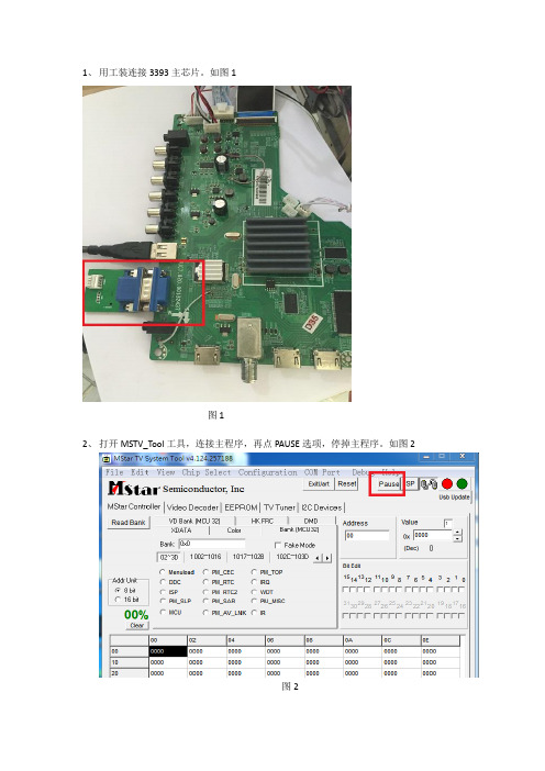
1、用工装连接3393主芯片。
如图1
图1
2、打开MSTV_Tool工具,连接主程序,再点PAUSE选项,停掉主程序。
如图2
图2
3、同工装连接6M50 DEBUG 端口,如图3:
图3
4、打开ISP_TOOL工具,点击CONNECT选项,如图4:
图4
5、在Config选项里,将ISP Slave Address设为0x98,Serial Debug Slave Address设为0XB4.
如图5:
图5
6、点击Read,下载6M50文件带工具中。
如图6:
图6
7、选择Auto选项,在子页面中勾选ALL Chip,Blank,Program,Verify,Exit选项,选好之
后,点击RUN按钮,程序开始升级,升级完毕后,重新开关机。
(备注:1、在升级过程中屏幕会切换老化模式,这是正常现象,升级完毕后可恢复正常。
2、若升级完软件后屏幕不开机或者半边屏花屏,是由于6M50升级不成功导致,重新升级即可。
)如图7:
图7。
升级BIOS和固件微码程序
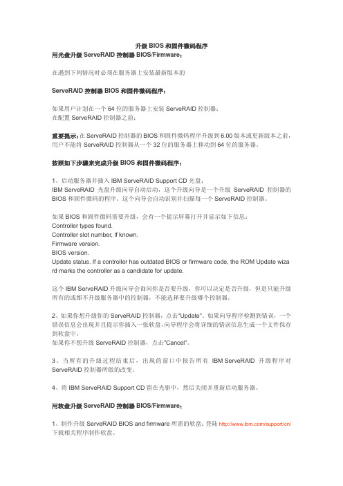
升级BIOS和固件微码程序用光盘升级ServeRAID控制器BIOS/Firmware:在遇到下列情况时必须在服务器上安装最新版本的ServeRAID控制器BIOS和固件微码程序:如果用户计划在一个64位的服务器上安装ServeRAID控制器;在配置ServeRAID控制器之前;重要提示:在ServeRAID控制器的BIOS和固件微码程序升级到6.00版本或更新版本之前,用户不能将ServeRAID控制器从一个32位的服务器上移动到64位的服务器。
按照如下步骤来完成升级BIOS和固件微码程序:1、启动服务器并插入IBM ServeRAID Support CD光盘;IBM ServeRAID光盘升级向导自动启动,这个升级向导是一个升级ServeRAID控制器的BIOS和固件微码的程序。
这个向导会自动识别并扫描每一个ServeRAID控制器。
如果BIOS和固件微码需要升级,会有一个提示屏幕打开并显示如下信息:Controller types found.Controller slot number, if known.Firmware version.BIOS version.Update status. If a controller has outdated BIOS or firmware code, the ROM Update wiza rd marks the controller as a candidate for update.这个IBM ServeRAID升级向导会询问你是否要升级,你可以决定是否升级,但是只能升级所有的或都不升级服务器中的控制器,不能选择要升级哪个控制器。
2、如果你想升级你的ServeRAID控制器,点击"Update"。
如果向导程序检测到错误,一个错误信息会出现并且提示你插入一张软盘,向导程序会将详细的错误信息生成一个文件保存到软盘中。
如果你不想升级ServeRAID控制器,点击"Cancel"。
AMS设备微码升级方案

AMS设备微码升级方案随着科技的发展,越来越多的设备需要进行微码(firmware)升级。
AMS设备是指运用了先进制造技术,能够将安全性、稳定性以及可用性融入到设备及系统功能中的自动化系统。
AMS设备的微码升级方案是指通过对设备中的微码进行更新,从而提高设备的性能、安全性和可靠性。
1.评估升级需求:首先,需要对设备的性能和功能进行评估,确定是否需要进行微码升级。
要考虑的因素包括设备的硬件和软件配置、设备的使用情况、设备的安全性需求等。
2.开发升级计划:根据评估结果,制定一个详细的升级计划。
升级计划应包括升级的目标,升级的内容和功能,升级的时间表,以及升级的流程和方法等。
3.开发微码升级包:根据升级计划,开发微码升级包。
升级包应包括需要更新的微码文件,以及更新微码的工具和方法。
4.测试微码升级包:在将微码升级包应用到实际设备之前,需要对微码升级包进行测试。
测试应包括对升级包的功能和性能进行验证,以及对升级包的稳定性和安全性进行测试。
5.准备升级环境:在准备升级环境之前,需要对设备进行备份。
升级环境应包括一台能够与设备进行通信的计算机,以及能够在设备上进行微码升级的工具和软件。
6.实施微码升级:将微码升级包应用到设备中。
这一步包括将微码升级包上传到设备中,然后通过升级工具和软件进行微码的更新。
7.验证微码升级:在完成微码升级之后,需要进行验证,确保升级成功并且设备正常工作。
验证应包括对设备功能和性能的测试,以及对设备的安全性进行评估。
8.更新文档和记录:及时更新文档和记录,记录微码的升级过程和结果,以及出现的问题和解决方案。
这些记录有助于后续微码升级的参考。
以上是一个AMS设备微码升级方案的简要步骤。
需要注意的是,在实施微码升级前,必须确保设备的备份和数据的安全性,以避免因微码升级而导致数据丢失或损坏的风险。
此外,由于微码升级涉及到设备的性能和功能的改变,可能会对设备的稳定性和可用性产生影响,因此应事先进行充分的测试和验证,确保升级的稳定性和安全性。
AMS设备微码升级方案
AMS设备微码升级方案陕西XXHDS设备微码升级方案XX公司20__年十一月目录一、概述.二、版本分析.1.目前设备微码版本情况.2.当前本.3.升级后微码的版本情况.三、微码升级的过程.四、升级注意事项4.五、回退方案一、概述XX公司(HitachiDataSystem,简称HDS)目前为陕西XX提供了4台AMS000作为生产系统存储设备。
HDS公司计划将该存储设备进行微码升级,修正其中可能存在的错误,进一步提高存储系统的高可用性,充分保障用户数据完整与一致。
本次升级只针对7层的AMS000(770033)进行。
二、版本分析1.目前设备微码版本情况设备名称设备用途序列号微码版本AMS000Product770XXXX3076-H2.当前本HDSAMS存储设备的稳定微码版本如下:设备名称微码版本AMS200078-SAMS500078-MAMS000078-H以上版本为HDS公司推荐的的微码版本,有多项内容,可解决存储与相关运行平台潜在问题,不致影响生产系统的正常运作。
3.升级后微码的版本情况设备名称设备用途序列号微码版本AMS000Product770XXXX3078-H三、微码升级的过程本次AMS微码升级采用offline升级方式。
升级完成后存储会重启,整个升级过程持续约半小时左右。
微码升级步骤:确认没有主机访问磁盘阵列。
使AMS进入维护模式。
进入web管理页面,当提示输入用户和密码时,输入maintenancosyu9500。
注意画面显示MaintenanceMode,点击Microprogram。
选择微码位置及微码安装方式,点击install。
开始安装微码,微码安装完成后按OK。
回到维护模式主画面。
按GotoNormalMode.磁盘阵列自动Reboot。
磁盘阵列重起(Reboot)完成后,检查磁盘阵列的状态,包括微码版本。
四、升级注意事项从078及以下版本升级需要采用OFFLINE的方式。
ATTO FibreBridge 6500 开始指导手册说明书
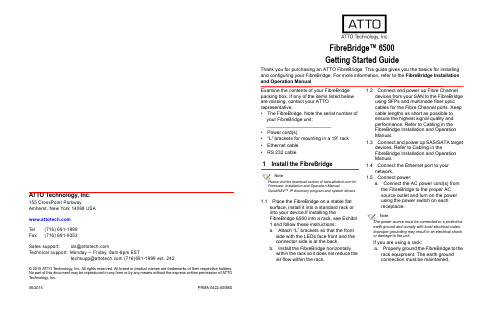
ATTO Technology, Inc.155 CrossPoint ParkwayAmherst, New York 14068 USA Tel (716) 691-1999Fax (716) 691-9353Sales support:****************Technical support: Monday -- Friday, 8am-6pm EST*********************(716)691-1999ext.242© 2015 ATTO Technology, Inc. All rights reserved. All brand or product names are trademarks of their respective holders.No part of this document may be reproduced in any form or by any means without the express written permission of ATTO Technology, Inc.06/2015 PRMA-0422-000MDFibreBridge™ 6500Getting Started GuideThank you for purchasing an ATTO FibreBridge. This guide gives you the basics for installing and configuring your FibreBridge. For more information, refer to the FibreBridge Installation and Operation ManualExamine the contents of your FibreBridge packing box. If any of the items listed below are missing, contact your ATTO representative.•The FibreBridge. Note the serial number of your FibreBridge unit:________________________•Power cord(s)•“L” brackets for mounting in a 19” rack •Ethernet cable •RS 232 cable1Install the FibreBridgeNotePlease visit the download section of for Firmware, Installation and Operation Manual,QuickNAV™ IP discovery program and system drivers1.1Place the FibreBridge on a stable flatsurface, install it into a standard rack or into your device.If installing theFibreBridge 6500 into a rack, see Exhibit 1 and follow these instructions:a.Attach “L” brackets so that the frontside with the LEDs face front and the connector side is at the back.b.Install the FibreBridge horizontallywithin the rack so it does not reduce the air flow within the rack.1.2Connect and power up Fibre Channeldevices from your SAN to the FibreBridge using SFPs and multimode fiber optic cables for the Fibre Channel ports. Keep cable lengths as short as possible to ensure the highest signal quality and performance. Refer to Cabling in the FibreBridge Installation and Operation Manual.1.3Connect and power up SAS/SATA targetdevices. Refer to Cabling in theFibreBridge Installation and Operation Manual.1.4Connect the Ethernet port to yournetwork.1.5Connect power:a.Connect the AC power cord(s) fromthe FibreBridge to the proper AC source outlet and turn on the power using the power switch on each receptacle.NoteThe power source must be connected to a protective earth ground and comply with local electrical codes. Improper grounding may result in an electrical shock or damage to the unit.If you are using a rack:a.Properly ground the FibreBridge to therack equipment. The earth ground connection must be maintained.b.The power requirements plus the powerdraw of the other equipment in the rackmust not overload the supply circuit and/or wiring of the rack.1.6Wait up to two minutes for the FibreBridgeReady LED to light indicating theFibreBridge has completed its power-on self test sequence.2Discover the IP addressNoteThe FibreBridge is initially configured with DHCPenabled. It is best if you have access to a DHCP server.2.1Work from the computer attached to theFibreBridge Ethernet port on the samedomain. From the download section of, run the QuickNav Utility QuickNAV-windows.exe for Windows orQuickNAV-Mac for Mac OS X.2.2Locate the FibreBridge with the serialnumber recorded earlier.2.3Highlight the serial number.2.4Click Next.If a DHCP server is available on your network, an address is assigned automatically by the server. Note the assigned address:____________________________________ If you do not have a DHCP server, get an IP address and subnet mask from your network administrator, type it into the area provided, and click on Next.2.5Click on Launch BrowserYour browser points to the ATTOExpressNAV splash screen. If you useInternet Explorer as a browser, continue on to Internet Explorer setup below. If not, continue on to Begin initial configuration .3Internet Explorer setup3.1Open your browser3.2Select Internet Options.3.3In the Internet Options screen, select theSecurity tab.3.4Click on the Trusted Sites icon.3.5Click on the Sites button.3.6In the text box Add this Web site to thezone, add the IP address of the appliance.You may use wild cards.3.7Click on Add3.8Uncheck the Require server verificationcheck box.3.9Click OK.3.10At the bottom of the Internet Options box,click on OK and close the box.4Begin initial configuration4.1The ExpressNAV System Managerwelcome screen appears. Click on EnterHere4.2Type in the user name and password.NoteThe default values are user name root and passwordPassword. The user name is case insensitive and thepassword is case sensitive.It is best practice to changethe default user name and password.4.3You are now ready to configure theFibreBridge for use. For more information,refer to the Installation and OperationManual.5Using with Tape5.1If using with a stand alone drive no furtherconfiguration is required.5.2If using with a library or autoloader with atape medium changer proceed to thefollowing instructions:e telnet or serial CLI (to map all tapedevices to a single fibre channel port).b.Set FcMultiNode enabled.c.Saveconfiguration Restart (wait forreboot and a ready prompt).d.Automap [N] (where N= 1 or 2).5.3If mapping to a single port is not required,issue an Automap to distribute devicesevenly.Exhibit 1Brackets to install the FibreBridge into a rackExhibit 2FibreBridge 6500S, LEDs, power receptacleand portsExhibit 3FibreBridge 6500D, LEDs, power receptacleand ports。
升级微码总结
The current temporary system firmware image is 0000
The system is currently booted from the permanent firmware image.
ftp> cd /tmp/fwupdate
250 CWD command successful.
ftp> pwd
257 "/tmp/fwupdate" is current directory.
ftp> bin
200 Type set to I.
ftp> bin
200 Type set to I.
注意:此选项不会要求确认,除非你确定要这样做,否则不要选择此项
这个过程将会运行10分钟左右,成功完成之后,如果提交的微码版本是SF220,那么需要手动关机,并重新启动机器,如果提交的微码版本是SF222或更高,就不需要关机和重启了。使用命令#lsmcode查看当前的微码
The current permanent system firmware image is 01SF240_338
ftp> put 70286C4F.BIN
200 PORT command successful.
150 Opening data connection for 70286C4F.BIN.
226 Transfer complete.
ftp: 发送 4430377 字节,用时 0.97Seconds 4572.11Kbytes/sec.
升级微码
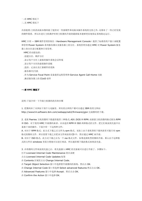
一.有HMC情况下二.无HMC情况下内容提要:主机的高版本微码除了提供对一些新硬件和高版本操作系统的支持之外,还修补了一些已经发现的硬件隐患。
所以在进行主机维护时将主机微码升级到最新版本能够更好地保证系统稳定运行。
HMC介绍 -- IBM硬件管理控制台(Hardware Management Console)提供了标准的用户接口来配置和管理Power System系列服务器以及服务器上的分区。
系统管理员通过HMC对Power System服务器上的分区进行配置和日常管理。
HMC的功能包括:.创建分区,维护分区.显示每个分区上虚拟的操作系统会话终端.显示每个分区的虚拟操作面板.监控,记录以及汇报硬件的更换.服务器开/关机.作为Service Focal Point设备提供远程管理和Service Agent Call-Home功能.激活服务器上的CUoD部件一.有HMC情况下说明:下面介绍一下升级主机微码的具体步骤1. 把微码补丁从网站下到个人电脑里。
所有的公网用户都可以通过IBM的英文网站/webapp/set2/firmware/gjsn完成微码的下载。
2. 老款Pseries主机的微码下载通常提供三种格式:AIX,DOS和RPM;而新款主机的微码格式则为RPM 和ISO。
对于使用HMC升级微码来讲,应该选用RPM和ISO两种格式的文件。
把它们刻录到光盘中以备接下来的操作。
下面介绍一下这两种文件:A. 对应于RPM格式:此方式下载之后文件为.rpm格式。
实际上由于老机型的下载列表里可能只有rpm 格式的微码文件,所以需要下载之后把该文件刻录到CD中,然后通过HMC来升级。
B. 对应于ISO格式:此方式下载之后为一个.iso格式文件。
如果是新机型的微码升级,那么由于这种格式的文件在windows里很方便地可以进行刻录,所以通常都下载此格式来刻录光盘。
3. 在将微码文件刻录到光盘之后,将光盘插入HMC的光驱就可以进行升级了,步骤如下:打开Licensed Internal Code Maintenance的目录树点击Licensed Internal Code Updates标签在Contents区域里点击Change Internal Code.在Target Object Selection窗口中选择要升级微码的系统,然后点OK.在Change Internal Code窗口里选择Select advanced features然后点击OK.在Advanced Features窗口中选择Accept,然后点击OK.在Confirm the Action窗口中选择OK.升级操作大概需要持续10分钟左右即可完成。
升迈方案升级说明书

已經掛載過XC3088裝置驅動程式的PC不需再重複進行 此一工作
-21-
標準操作流程
2. 確認勾選項目
1. 根據前述畫面功能說明,勾選升級項目
3. 在”系統檔與預先放置到裝置的檔案”清單中加入系
統檔(1)及其他選項所需的檔案(2),若有需要預先 放入的歌曲檔也一併放入(3)
-22-
標準操作流程
4. 設定磁碟標籤
BR3199 Promotion tool instruction booklet
User Guide Version 2010.04.30
範圍
本版修訂項目 操作說明
系統需求 畫面功能說明
主頁 進階設置頁
標準操作流程 顯示訊息說明
-2-
修訂項目
2009/08/28
Release ver 0.5
2009/12/18
※ 若Flash非新品或正品,可由Flash供應商先以低格但不勾選韌體安裝的方式進行 壞塊掃瞄,再交由MP3製造廠進行韌體安裝程序,可節省製造廠的生產時間
-6-
畫面功能說明--主頁
安裝ISO檔 安裝產生CDROM光盤的光盤映像檔 預設不勾選,若需此功能, “系統檔與預先放置到裝置的檔案”清單必需有 image.iso 檔案 韌體檢查 安裝完成時對寫入的program.bin做讀回確認,可確保升級的可靠度 預設為勾選 手動模式 開啟本項目時,當有裝置插入PC時,訊息字串由”等待裝置插入”變更為”裝 置插入”,但不立即進行升級動作,需等操作者按下”開始升級”按鍵才會啟動 升級動作 預設不勾選 自訂系統區 供軟體開發者對將來系統區擴充需求的設定項目,預留系統區擴充空間,可避 免韌體升級需重新格式化磁碟。 預設不勾選
-9-
ATT官解填写内容

ATT官解填写内容在开始之前先说几个常见的问题:1.网站检测是白名单,但是官解网站显示的的设备是被偷状态(黑名单)或欠费;2.无法点击下一步,下一步的按钮是灰色的;3.出现“Looks like we're already processing a request for this IMEI. Check your request status for more info.”,以上就是教程大家常见的问题。
新手在官解ATT手机的时候会经常出现上面两种情况,当遇到第一种情况的时候以官网官解网站的提示为准,因为部分查询网站会有信息滞后,另外我推荐大家官解ATT直接上官网解锁,可以不用先查询(找别人解锁除外);另外一个问题就是无法下一步,这个问题主要是科学上网失败(部分小白用户是没确认人机验证导致是灰色无法点击),在访问国外网站的时候是需要科学上网的,另外有些浏览器的问题,如果你的网络能访问国外网站(例如:Facebook、YouTube等),但是依旧无法下一步,请这个时候换个浏览器。
另外大家在解锁ATT设备的时候会不会出现“Looks like we're already processing a request for this IMEI. Check your request status for more info.”,出现这种情况的时候多半是因为之前你提交请求的邮件你没有确认成功。
(有时候你确实点了确认,但是因为网络的原因确认失败)我也出现过这种情况,我的情况是当时网络不稳定导致邮件确认失败了,其实因为我换卡比较少,自己对卡贴也非常了解,卡贴机在我手上就是无锁,所以就没有过于在意,直到上个周末发现我的解锁状态还是停留在准备阶段,然后我才知道原来自己也出现了确认失败的情况。
我认为失败就失败了,重新提交一下就行了,于是接下来就出现了前面说的“Looks like we're already processing a request for this IMEI. Check your request status for more info.”,这就很尴尬了,之前的提交我看了下时间是7月份,现在已经快10月份,也就是快三个月我的需求失败了也不能再次提交,不得不说这种体验真的好差。
P5微码升级(超详细)

May 20061 Overview1.1 p5 server hardware1.2 System firmware fixes and upgrades1.3 Decoding firmware names1.4 Decoding the operator control panel1.5 Temporary versus Permanent Firmware sides1.6 Be Advised2 Requirements2.1 Software requirements3 Upgrade firmware with HMC3.1 Connectivity3.2 HMC requirements3.3 Viewing system firmware information using LIC wizard3.4 Upgrade system firmware to a new release using HMC3.5 Update system firmware within a release using HMC3.6 Change License Internal Code Wizard3.7 Reject the installed firmware using a HMC4 Upgrade firmware without a HMC4.1 Access ASMI via serial console4.2 Checking the current firmware level4.3 Power on using ASMI4.4 Upgrade system firmware via running operating system4.4.1 Upgrade firmware image using AIX4.4.2 Upgrade firmware image using Linux4.5 Upgrade firmware using diagnostics CD5 Reject installed firmware without an HMC5.1 Boot to the permanent side5.2 Reject the installed firmware using an OS command5.3 Reject the installed firmware using a diagnostic CD6 Appendix common problems7 ReferencesThe goal of this paper is to provide easy-to-read instructions to quickly update system firmware on p5 servers. It is assumed the reader has basic p5 skills. There are extensive references that should help with items not covered in this paper.Three firmware update methods will be covered:1. Update on an HMC managed system2. Update on a standalone server via OS, without a HMC3. Update on a standalone server using the Diagnostic CD, without a HMCPlease first read through the prerequisites before getting started on any of these upgrade sections. Then refer to any one section or all sections when choosing the preferred method for updating system firmware.1.1 p5 server hardwareThe hardware used in developing this paper was a p5 550Q (type-model 9133-55A). HMC (version 5.2.0 including fix MH00586) was also used when needed.1.2 System firmware fixes and upgradesFirmware, also known as microcode, is Licensed Internal Code that fixes problems and enables new system features as they are introduced. New features introduced are supported by new firmware release levels. In between new hardware introductions, there are fixes or updates to the supported features. These fixes are often bundled into service packs. A service pack is referred to as an update level. A new release is referred to as an upgrade level. Both levels are represented by the file name in the form of PPMMXXX_YYY_ZZZ. PP and MM are package and machine type identifiers. PP can be 01 for managed system or it can be 02 for power subsystem. The MM identifier is a SF for p5 systems and a BP for Bulk Power Controller. The firmware version file applicable to p5 machines is in the form of 01SFXXX_YYY_ZZZ.1.3 Decoding firmware namesThe file naming convention for system firmware is:01SFXXX_YYY_ZZZ, whereXXX is the stream release levelYYY is the service pack levelZZZ is the last disruptive service pack levelUsing the above example, the system firmware 01SF235_185 would be described as release level 235, service pack 185.Each stream release level supports new machine types and/or new features.Firmware updates can be disruptive or concurrent. A disruptive upgrade is defined as one that requires the target system to be shutdown and powered off prior to activating the new firmware level. A new release level upgrade will always be disruptive. All other upgrades are defined as concurrent, meaning that they can be applied while the system is running. Concurrent updates require an HMC but are not guaranteed to be non-disruptive.In general, a firmware upgrade is disruptive if1. The release levels (XXX) are different.Example: Currently installed release is SF230, new release is SF2352. The service pack level (YYY) and the last disruptive service pack level (ZZZ) are equal. Example: SF235_180_180 is disruptive, no matter what level of SF235 is currently installed on the system3. The service pack level (YYY) currently installed on the system is lower than the last disruptive service pack level (ZZZ) of the new service pack to be installed.Example: Currently installed service pack is SF235_180_180 and the new service pack isSF235_190_185An installation is concurrent if:1. The service pack level (YYY) is higher than the service pack level currently installed on your system.Example: Currently installed service pack is SF235_180_160, new service pack isSF235_185_160.1.4 Decoding the operator control panelWhen the system is powered on, note the operator control panel. It should appear similar to the image below.01 N V=FHMC=1 TIn this example the system is currently booted from the temporary side of the firmware image as denoted in the control panel by the letter T. This indicates the firmware is running from the temporary side. N indicates the system is booted in normal mode. V=F indicates the boot speed is set to Fast. HMC=1 indicates that the server is managed by and connected to one HMC.If it has been recently managed by an HMC and no HMC is connected then it will display HMC=0. If no HMC is available and it is desired to set the server to unmanaged it might be required to reset the service processor to factory default using ASMI.1.5 Temporary versus Permanent Firmware sidesThe Service Processor maintains two copies of firmware, the temporary and permanent side, to help manage and reduce the frequency of downtime for maintenance. The permanent side is also known as the "P" side. The temporary side is also known as the "T" side. Server firmware fixes are installed on the temporary side. Copying the temporary firmware level to the permanent side is known as committing or accepting the fix. Conversely, rejecting, or removing the current firmware level consists of copying the permanent firmware image to the temporary side.Note: It is recommended to use a new firmware fix for a period of time before committing (or accepting) it.If firmware fixes are applied consecutively, the first fix will, by default, be copied from the temporary to the permanent side, or accepted. Using an HMC, it is possible to simply replace the temporary image by doing an Install and Activate of the new firmware and indicating that the firmware should not be accepted.1.6 Be AdvisedDuring a firmware update, the flashing of the NVRAM might take anywhere from ten minutes to one hour. In general, updating to a new release level will take longer. Ensure the system is not interrupted before the flash process is completed. Interrupting this process could result in a service call.For systems that are not managed by a HMC, the installation of system firmware is always disruptive. During the update_flash process, the console output will be displayed. Again, do not interrupt this process.Restarting system.FLASH: preparing saved firmware image for flashFLASH: flash image is 35191632 bytesFLASH: performing flash and rebootFLASH: this will take several minutes. Do not power off!2.1 Software requirementsThe table below is a summary of the minimum components required for each method covered in this paper:There are two very helpful sites that will assist in gathering the components necessary to update firmware. Visiting the Microcode downloads site ( 1) is recommended before performing any updates./webapp/set2/firmware/gjsnFigure 1To download the rpm and XML files, input the server machine type and model number and select the latest firmware components based on the below requirements table (option 1 in Fig 3).If planning to using the Diagnostic CD method, use option 4 to download the firmware image ISO image. The rpm files are not directly compatible with the Diagnostics CD. For the smallest ISO image take the following path using option 4Obtain ISO Image -> Download P5 Microcode -> Select one -> GONext, go to the Power5 Code matrix site (Figure 2) to ensure the existing code levels support thedownloaded firmware release. For the purposes of this paper, this applies mostly to HMC version level. If an HMC is not being used, this is for information only.https:///webapp/set2/sas/f/power5cm/home.htmlFigure 23.1 ConnectivityThe HMC is connected to a p5 system with a standard TCP/IP Ethernet connection. Figure 1 shows a very simple connection.Figure 3.p550Q server with a direct connection to a HMC.3.2 HMC requirementsBefore applying the latest level of firmware on the system using a HMC it might be required to update the build version. Please see the recommended HMC level for the target firmware level in the Power5 Code Matrix. It is always a good idea to have a suitable backup of the HMC data before updating HMC code.In this example, per the Power5 Code Matrix for system firmware SF240_202, the recommended code level for our HMC is Version 5.2 plus service pack MH00586. This is also the most current level at the writing of this paper.Check the HMC version build level by clicking on the HMC Code Update in the HMC navigation area (Figure 4):Figure 4The HMC version can also be checked as hscroot from the shell prompt as follows:hscroot@c76v3hmc01:~> lshmc -V"version= Version: 5Release: 2.0HMC Build level 20060210.1MH00586: Required fixes for HMC V5R2.0(02-14-2006)","base_version=V5.2.0"3.3 Viewing system firmware information usingLIC wizardFrom the navigation area, select License Internal Code Updates. In the content area, click on Change Licensed Internal Code to the current release. In the Target Object Selection window, click the target system, and click OK.Figure 5In the Change Internal Code window, select View system information and click OK. From the main Change Internal Code task panel, select View system information and click OK. To view the installed, activated, and accepted LIC levels on the target, select "None" on the Specify LIC Repository panel and click OK.Figure 63.4 Upgrade system firmware to a new release using HMCRemember, upgrading to a new release is a disruptive upgrade.Start by opening the Server and Partition folder in the HMC. Then, click on Server Management in that folder. If the state of the machine is Power off, Ready, or Standby, then proceed. Setting the state to Power off is recommended when performing a firmware upgrade, although it is not required. Note: only HMC managed systems can perform firmware upgrades with target system set to Power off state.Figure 7Next, open the Licensed Internal Code Maintenance folder on the Hardware Management Console. Then, click on Licensed Internal Code Updates in that folder. In this example, the update will be from our current firmware level 01SF235_185 to 01SF240_202, so the normal " Change Licensed Internal Code for the current release" feature will not work. Select Upgrade Licensed Internal Code to a new release.Figure 8Select the desired target managed system and click OK.Figure 9Insert the CD with the rpm and XML files into the drive. On the Specify LIC Repository panel, select DVD drive and click OK.Next, a Select LIC level panel is shown. Click OK.Figure 11The next prompt will be to accept the LIC license agreement for machine code. Read the license and click OK to accept. After accepting the license agreement, confirm the disruptive upgradeaction. Click OK to proceed. When the firmware is flashed, the FSP will restart and activate the new firmware level.Figure 12A dialog box will appear to showing the elapsed time and status of the firmware upgrade.WARNING - During a disruptive update, the flashing of NVRAM might take from ten minutes to two hours. Do not interrupt the process before the flash process is complete.Figure 13Once the firmware upgrade has completed, view the system firmware information to see how the upgrade has changed what is available.3.5 Update system firmware within a release using HMCFirmware updates within a release are common when maintaining and managing a p5 server.Use the Change Licensed Internal Code for the current release feature to install LIC updates on p5 servers. Updates can be applied to managed systems, bulk power controllers, and I/O adapters. This example shows updating a managed systems LIC from an installed firmware level of 01SF235_180_160 to 01SF235_185_160. Note that the release level will remain the same, but the service pack level will be updated from 180_160 to 185_160. The update is concurrent, or non-disruptive, as indicated in the service pack (185) and the last disruptive (160) levels.3.6 Change License Internal Code WizardStart by opening the Server and Partition folder in the HMC. Then, click on Server Management. Verify that the target system exists in the content area.Figure 14From the HMC left navigation area, open the Licensed Internal Code Maintenance folder. Click on Licensed Internal Code Updates. Select the Change Licensed Internal Code for the currentrelease feature.Highlight the target managed system and click OK (Figure 15).Figure 15Click the OK button to start the Change Licensed Internal Code wizard.Figure 16Insert the CD into the drive and on the Specify LIC Repository panel, select DVD drive and click OK.The following panel is displayed providing summary information about the update. Note the Advanced Options button gives the option to view and change the installation type for this update action. The current install type selection is Concurrent install and activate. Other installationtypes involve either a deferred or an immediate system restart to activate the new firmware level. Those installation types are grayed out since this is a concurrent update only. (See Managed System and Power Licensed Internal Code (LIC) Concurrency panel below.)Click Next to continue with Concurrent install and activate. Please read the license agreement and click OK to accept.Figure 16The Advanced Option button displays the Managed System and Power Licensed Internal Code (LIC) Concurrency panel:Figure 17After accepting the license agreement, confirm the concurrent update action prompt. Click Finish and Close to proceed.Figure 18A progress window will appear to show the elapsed time and status of the firmware update. When the firmware is flashed, the FSP will restart and activate the new firmware level.Figure 19Once the firmware upgrade has completed, view the system firmware information to see how the upgrade has changed what is available.3.7 Reject the installed firmware using a HMCFrom the HMC left navigation area, select License Internal Code Updates.In the content area, click Change Licensed Internal Code to the current release. In the Target Object Selection window, click the target system, and click OK.The main panel then displays with three options start the Change Internal Code wizard, view system information, and select advanced features.Figure 20The Remove and activate feature is a one step process to remove the current active T-side firmware and roll back (or copy) firmware from the P-side. Essentially, undo the last firmware update and restore the T-side with the P-side firmware version.Figure 214.1 Access ASMI via serial consoleA system with no HMC is also known as an unmanaged system. ASMI is used to power on the system and perform other useful functions. Using a serial cable and a program like HyperTerminal on Windows, ASMI and the active console can be accessed. Other communication programs should work.Figure 22.Back view of p550Q server with ports for (left to right)serial, SPCN, HMC, USB and Ethernet.Once the serial connection to the system is established, press the <ENTER> key, to be presented with the following ASMI login screen.WelcomeMachine type-model: 9133-55ASerial number: 10B7D4GDate: 2006-4-21Time: 20:12:48Service Processor: PrimaryUser ID: adminPassword: *****User ID to change: adminCurrent password for user ID admin: *****New password for user: ******New password again: ******Operation completed successfully.PRESS ENTER TO CONTINUE:Number of columns [80-255, Currently: 80]:Number of lines [24-255, Currently: 24]:Type the User ID and password to log in to ASMI. If this is the first time logging into ASMI, it might be required to change the default password. The default password is admin4.2 Checking the current firmware levelUpon logging into ASMI, the firmware level will be clearly displayed as shown below.System name: Server-9133-55A-SN10B7D4GVersion: SF235_185User: adminCopyright © 2002-2005 IBM Corporation. All rights reserved.1. Power/Restart Control2. System Service Aids3. System Information4. System Configuration5. Network Services6. Performance Setup7. On Demand Utilities8. Concurrent Maintenance9. Login Profile99. Log outThe current activated firmware level is also shown in the ASMI web interface after logging in. To see the firmware level, look in the upper-right corner. Basically, to access the ASMI web interface, connect an Ethernet cable directly to the HMC1 port. For details on accessing the ASMI web interface, see reference 6.Figure 23The current active firmware level can also seen from the output of the Display Microcode Level selection on the Diagnostics CD. Details of how to get to the following screen are provided in 4.7Figure 24The current active firmware level as seen from the SMS screen:Figure 25Finally, if the server has a running AIX or Linux operating system with the Service and Productivity tool lsvpd installed, the lsmcode command can be used as shown below. More details are provided in section 4.4.2linux:~ #/tmp/fwupdate # lsmcodeVersion of System Firmware is SF235_185 (t) SF235_185 (p) SF235_185(b)Version of PFW is 17112005111681CF06814.3 Power on using ASMIFrom the ASMI main menu select 1. Power/Restart Control to get to this screen:Power/Restart Control1. Power On/Off System2. Auto Power Restart3. Immediate Power Off4. System Reboot5. Wake On LAN98. Return to previous menu99. Log outS1> 1Select 1. Power On/Off System.On the next screen select 8. Power on. Wait for a few seconds to be logged out as the system powers on. Watch boot progress codes as the system comes up.Power On/Off SystemCurrent system power state: OffCurrent firmware boot side: PermanentCurrent system server firmware state: Not running1. System boot speedCurrently: Fast2. Firmware boot side for the next bootCurrently: Permanent3. System operating modeCurrently: Normal4. AIX/Linux partition mode bootCurrently: Continue to operating system5. Boot to system server firmwareCurrently: Standby6. System power off policyCurrently: Stay on7. i5/OS partition mode bootCurrently: A8. Power on98. Return to previous menu99. Log outS1>8When the system completes the boot process, note the operator control panel. Note that there should be no indication of HMC=. This indicates that the service processor does not expect to bemanaged by an HMC (see below).01 N V=FT4.4 Upgrade system firmware via running operating systemThe rpm file for the firmware fix file stored either in the file system or on a mounted CD. For this example, the rpm file is in the /tmp directory.Run the command below to extract the flash image file in the rpm file:rpm -Uvh --ignoreos /tmp/01SF240_202_201.rpmThe flash image file is put into a newly created directory /tmp/fwupdateTo install the server firmware through a running OS, use the update_flash. To run this command, root authority is required. Since installing server firmware fixes through the operating system is a disruptive process, shut down any running applications and logout any non-root users.On AIX, the update_flash command is located in the /usr/lpp/diagnostics/bin directory. If this directory does not exist, install the AIX diagnostics to run this command.On Linux, the update_flash command is located in the /usr/sbin directory. A separate installation of Service and Productivity Tools may be required.The command syntax is as follows (for both AIX and Linux):update_flash [-f file_name]| [-c] | [-r]Attention: The update_flash command reboots the entire system. Do not use this command if more than one user is logged in to the system.FlagDescription-f <file_name>Flash update image file source. The file_name variable specifies the fully qualified path of the flash update image file.-cCommit temporary image to permanent side.-rReject temporary image.4.4.1 Upgrade firmware image using AIXBefore installing check the existing firmware level. From AIX, use the command lsmcode. This command resides in the diagnostic directory. An example of the output of the lsmcode command is as follows:DISPLAY MICROCODE LEVEL 802811IBM,9133-55AThe current permanent system firmware image is SF235_185The current temporary system firmware image is SF235_185The system is currently booted from the temporary firmware image.Enter to continue.Next, run the update_flash command to upgrade firmware:[c73m5lr01][/]> ls /tmp/fwupdate01SF240_202_201[c73m5lr01][/]> /usr/lpp/diagnostics/bin/update_flash -f/tmp/fwupdate/01SF240_202_201The image is valid and would update the temporary image toSF240_202.The new firmware level for the permanent image would be SF235_185.The current permanent system firmware image is SF235_185.The current temporary system firmware image is SF235_185.***** WARNING: Continuing will reboot the system! *****Do you wish to continue?Enter 1=Yes or 2=No4.4.2 Upgrade firmware image using LinuxTo use lsmcode and update_flash commands in Linux, the following minimum Service and Productivity tools have to be installed, and in this order:librtasppc64-utilslsvpdNote: If the Service and Productivity tools are not installed, they can be downloaded from the following location. Choose the appropriate Linux distribution and release.https:///webapp/set2/sas/f/lopdiags/home.htmlAfter downloading the Linux tools into the /tmp directory, install the three packages - Platform Enablement Library (librtas), Service Aids (ppc64-utils), and Hardware Inventory (lsvpd) as followslinux:~ # rpm Uvh librtas-1.1-17.ppc64.rpmlinux:~ # rpm Uvh ppc64-utils-2.1-0.ppc64.rpmlinux:~ # rpm Uvh lsvpd-0.12.7-1.ppc.rpmThe Hardware Inventory package contains the lsmcode command that allows us to view the current system firmware information. To populate the VPD database and enable this command, typelinux:~ # chkconfig lsvpd onlinux:~ # /sbin/update-lsvpd-dblinux:~ #/tmp/fwupdate # lsmcodeVersion of System Firmware is SF235_185 (t) SF235_185 (p) SF235_185(b)Version of PFW is 17112005111681CF0681Run the update_flash command to upgrade firmware:linux:/tmp/fwupdate # /usr/sbin/update_flash -f/tmp/fwupdate/01SF240_202_201info: Current Temporary side will be committed toPermanent side before being replaced with the new imageProjected Flash Update Results:Current T Image: SF235_185Current P Image: SF235_185New T Image: SF240_202New P Image: SF235_185Flash image ready...rebooting the system...The flash process will reboot the system as part of a disruptive install of the firmware. Do Not Power off or interrupt the flash process. When the new firmware is completely installed, log back into Linux and verify the current firmware configuration.linux:~ # lsmcodeVersion of System Firmware is SF240_202 (t) SF235_185 (p) SF240_202(b)Version of PFW is 13552006011081CF06814.5 Upgrade firmware using diagnostics CDThis method is intended for systems that are not managed by a HMC.Insert the diagnostics CD into the CD-ROM drive and connect to ASMI to power on or restart the system as described in 4.3.Press 1 after keyboard POST to in order to get the SMS menu screen. Watch closely as this passes quickly.Select the following SMS options and choose to boot from the CD device.5. Select Boot Options -> 1. Select Install/Boot Device -> 7. Listall devicesThis will look like a normal AIX boot with Welcome to AIX scrolling across the console.Once the Diagnostics disk has booted, on the function selection screen, select Tasks and Service Aids.Figure 27On the task selection screen, scroll to the bottom of the list of options, and select Update and Manage Flash.Figure 28Insert the CD containing the downloaded firmware img file into the media device, select Validate and Update System Firmware and Update System Firmware menu items.Figure 29Press F4 to select a firmware fix image file from a list of image files. Our CD contains only one version of the target firmware update file, and 01SF204_202_201.img is displayed.Figure 30Press F7 (commit). The server firmware level selected will be installed on the temporary side.There are times when it may be necessary to reject a firmware update. The reject function is accomplished by basically copying the P-side firmware to the T-side and activating. The rejected T-side firmware is removed completely. Without an HMC, it is possible to reject the firmware in the T-side and roll back to the firmware in the P-side using the OS update_flash command or a Diagnostics CD.Note: If rejecting firmware without an HMC, the server must be booted from the P-side copy of the firmware prior to performing this action.5.1 Boot to the permanent sideConnect to ASMI as described in section 4.1. Log in to ASMI and select 1. Power/Restart ControlSystem name: Server-9133-55A-SN10B7D2GVersion: SF235_185User: adminCopyright © 2002-2006 IBM Corporation. All rights reserved.1. Power/Restart Control2. System Service Aids3. System Information4. System Configuration5. Network Services6. Performance Setup7. On Demand Utilities8. Concurrent Maintenance9. Login Profile99. Log outS1> 1Select 1. Power On/Off SystemPower/Restart Control1. Power On/Off System2. Auto Power Restart3. Immediate Power Off4. System Reboot5. Wake On LAN98. Return to previous menu99. Log outS1> 1Select 2. boot side for the next bootPower On/Off SystemCurrent system power state: OffCurrent firmware boot side: TemporaryCurrent system server firmware state: Not running1. System boot speedCurrently: Fast2. Firmware boot side for the next bootCurrently: Temporary3. System operating modeCurrently: Normal4. AIX/Linux partition mode bootCurrently: Continue to operating system5. Boot to system server firmwareCurrently: Running6. System power off policyCurrently: Automatic7. i5/OS partition mode bootCurrently: A8. Power on98. Return to previous menu99. Log outS1> 2Select 1. PermanentFirmware boot side for the next bootCurrently: Temporary1. Permanent2. Temporary98. Return to previous menu without saving changes99. Log outS1> 1Note that the firmware boot side is now set to Permanent which is our backup copy of the firmware flash.Select 8. Power on. Hit the <ENTER> key. Wait for a few seconds to be logged out as the system powers on.Power On/Off SystemCurrent system power state: OffCurrent firmware boot side: TemporaryCurrent system server firmware state: Not running1. System boot speedCurrently: Fast2. Firmware boot side for the next bootCurrently: Permanent3. System operating modeCurrently: Normal4. AIX/Linux partition mode bootCurrently: Continue to operating system5. Boot to system server firmwareCurrently: Running6. System power off policyCurrently: Automatic7. i5/OS partition mode boot。
ATTO FastStream SC 5300imediaDock安装指导说明书

© 2007 ATTO Technology Inc. PRMA 000-0365-0001Parity protection kit for MediaDockInstallation GuideVerify the contents of your packing box• ATTO FastStream SC 5300. Note the serial number of your FastStream SC 5300 for later use: ____________________________• Power cord • Ethernet cable • RS-232 serial cable • “L” brackets• Setup CD including Express Power Center, ExpressStripe, QuickNAV, Benchmark tool, Celerity driver, installation guides and Installation and Operation ManualInstall the Celerity storage adapter1Power off your computer and install the ATTO Celerity storage adapter in the bottom PCI-X or PCIe slot of your HP XW Workstation.2Power up your system.3Install the Celerity driver by clicking thesetup.exe file located in the Celerity folder on the included setup CD. Follow the instructions and continue to the next step.NoteWindows ® users: click OK for each warning message box presented.Install the FastStream SC 53001Place the FastStream SC 5300 on a stable flat surface or install it into a standard 19” rack by attaching the supplied “L” brackets2Connect the Ethernet port to your network using a Cat 5e Ethernet cable or better.3Connect your SCSI cables to the MediaDock™ II chassis in single bus mode or split bus mode. See Exhibit 1 and Exhibit 2.Exhibit 1 FastStream SC 5300 in single bus attached to MediaDock II unitsExhibit 2 FastStream SC 5300 in split bus attached to a MediaDock II4Connect the LC-LC Fibre Channel cables from the FastStream SC 5300 to the Celerity storage adapter.5Connect the AC power cord from theFastStream SC 5300 to the proper AC source outlet.6Turn on power to the FastStream SC 5300 using the switch on the back of the appliance.Discover the IP address1Open the QuickNAV-windows.exe program found in the Utilities directory on the CDsupplied with your FastStream SC 5300.2The ATTO QuickNAV Wizard screen appears.Click Next.3Highlight the ATTO FastStream SC 5300 serialnumber. Refer to Verify the contents of yourpacking box on page 1.4Click Next.NoteIf a DHCP server is not available on yournetwork, refer to the Installation and OperationManual for further instructions.5Click on Launch Browser. The FastStream SC5300 GUI initial welcome screen appears.Initial configurationCAUTIONSelecting Commit during configurationcauses all previous storage data on drivesto be erased. Make sure data is backed up.1At the initial welcome screen for your ATTOFastStream SC 5300 in your web browser clickon Enter Here.2Enter the username and password in the loginbox. Default values are• Username: root• Password: Password.Passwords are case sensitive.3Click OK4At the Initial Setup screen, choose the AvidDigital Video button.5Click NextNoteThe FastStream SC 5300 supportsconfigurations of 6, 12 or 24 JBOD drives. Thedrives should be attached to the FastStreamSC 5300 and powered on.6All of your drives are displayed graphically onthe ATTO Digital Video Setup Wizard page.If no drives are present, make sure your drivesare powered on and attached to theFastStream SC 5300, then click the SystemScan button. If you do not see 6, 12 or 24drives, consult the Installation and OperationManual.7Click on Commit8 A warning asks to confirm your choice: settingup RAID groups destroys existing data.Select No to cancel the setup and return to theinitial setup page.Select Yes to set up RAID groups.Configuration may take more than two hours.N oteOnce the initial setup is complete, close yourbrowser and configure the RAID protectedstorage in your specified operating system.Refer to the Monitor page periodically to notesystem health.2..© 2007 ATTO Technology Inc. PRMA 000-0365-000© 2007 ATTO Technology Inc. PRMA 000-0365-000 3Set up Phone Home E-mail notification of system problems. Refer to the Installation and Operation Manual for more information.9The Health and Status Monitor page appears.PC users: continue to PC Users: Install ATTO Express Power CenterMac® users: continue to Mac users: install ATTO ExpressStripe .PC users: install ATTO Express Power CenterN oteFor 6-drive configurations, skip to Step 14 on page 3.1Open the Power Center folder on your setup CD.2Click on the ExpressPCI x86.msi file 3Follow the installation instructions.4Reboot the computer.5After the reboot, double click on the Express Power Center Utility shortcut on your desktop to start the program.6Press the Insert key on your keyboard and enter the name of the RAID group you want to create.7Press OK.N oteIf you are using a single bus configuration, you must create two RAID groups.8Click on the Members pane.9Press Insert on your keyboard.10Enter 128 KB in the Stripe Interleave text box.11If you have a split bus configuration, select bothRAID drives attached to your ATTO FastStream SC 5300.If you have a single bus configuration with 12 300GB drives or 24 drives, select • First RAID group:Channel 0 ID 0 LUN 0Channel 1 ID 0 LUN 0• Second RAID group:Channel 0 ID 0 LUN 1 Channel 1 ID 0 LUN 112Click the disk icon in the upper left hand cornerof the program to save the configuration.13Close the Express Power Center application.14On the desktop, right click on My Computer 15Choose Manage.16The Computer Management screen appears.Click on Disk Management .4..© 2007 ATTO Technology Inc. PRMA 000-0365-00017Select the new unpartitioned disk.18Write a basic signature.19Right-click the basic volume you just createdand format it NTFS just as you would any Windows volume.N oteIf you have 12 300GB drives or 24 drives, repeat this step because you have two volumes.20The setup of your storage is now complete andyou may begin using your FastStream SC 5300.21To ensure that your ATTO FastStream SC5300 has been configured properly, run the ATTO Disk Benchmark Tool included on your installation CD.Mac users: install ATTO ExpressStripe1Ensure the Celerity storage adapter (42ES or 42SX based on your system) has been installed in your Macintosh2In the CD included with your ATTO FastStream SC 5300, click on the Celerity Mac folder.3Click on the Disk Image file.4Install the ExpressStripe Application following the installation instructions.5Reboot your Mac.6Launch ExpressStripe and enter the following registration : Your NameCompany : ATTO FastStream SC 5300Serial Number : 100fb66bAuthorization Code: 27adwdd6q6wb3a72© 2007 ATTO Technology Inc. PRMA 000-0365-000 57Click on the Createbutton.8Click on theRAID 0 button.9Select all drives connected to the ATTO FastStream SC 5300 by clicking the open Applekey and A.10Click Next .11The Create RAID 0 Volumes screen appears.Click on Next .12The Create RAID 0 Array screen appears.Change the interleave size to 128KB.N oteYou may also change the name of the volume on this page13Click Finish .14On the final screen, click OK .The volume is created and its icon is placed onyour Desktop.15Verify that the volume is on the desktop. 16To ensure that your ATTO FastStream SC 5300 has been configured properly, run thebenchmark utility included in the ExpressStripe application.17Select Quit to exit from ExpressStripe and begin using your FastStream SC 5300.6..© 2007 ATTO Technology Inc. PRMA 000-0365-000。
brocade微码升级方案

微码升级方案环境:目前微码版本是7.0.0.c,升级到7.1.1.1过程如下1:升级前的准备:检查交换机的状态是否正常,保存配置信息2:升级过程:每台交换机2个CP,先升级一个CP,升级完后再升级另一个CP,所以每台交换机升级微码要升级2次.升级步骤1:微码路径:用ftp,制定微码目录,如下图2:登入交换机升级微码,先升级一个CPswitch:admin> firmwaredownloadType of Firmware (FOS, SAS, or any application) [FOS]:SASTarget Slots (all, or slot numbers) [all]:Server Name or IP Address: 192.168.32.10Network Protocol (1-auto-select, 2-FTP, 3-SCP) [1]:User Name: userfooFile Name: /home/userfoo/dist/release.plistPassword:3:然后查看微码是否升级完用firmwaredownloadstatus会有类似如下信息switch:admin> firmwaredownloadstatus[1]: Mon Dec 19 18:40:19 2007Slot 6 (CP1, active): Firmware is being downloaded to standby CP. This stepmay take up to 30 minutes.[2]: Mon Dec 19 18:46:18 2007Slot 6 (CP1, active): Firmware has been downloaded successfully to Standby CP. [3]: Mon Dec 19 18:46:25 2007Slot 6 (CP1, active): Standby CP is going to reboot with new firmware.[4]: Mon Dec 19 18:47:45 2007Slot 6 (CP1, active): Standby CP booted successfully with new firmware.[5]: Mon Dec 19 18:47:56 2007Slot 8 (FR4-18i): Firmware is being downloaded to the blade. This step maytake up to 10 minutes.[6]: Mon Dec 19 18:48:50 2007Slot 5 (CP0, active): Forced failover succeeded. New Active CP is running new firmware[7]: Mon Dec 19 18:48:57 2007Slot 5 (CP0, active): Firmware is being download to standby CP. This step may take up to 30 minutes.[8]: Mon Dec 19 18:49:28 2007Slot 8 (FR4-18i): Firmware has been downloaded successfully. Blade isrebooting with the new firmware.4:如果升级完再用如上方法升级另一个CP5:如果不成功退回原来的步骤跟上面的一样.。
ISC6500 网络存储系统 升级指导书
文档名称:《ISC6500网络存储系统升级指导书》 文档密级:内部公开 2022-04-26All rights reserved 版权所有,侵权必究 第i 页, 共62页产品名称Product name密级Confidentiality level ISC6500内部公开 产品版本Product versionTotal pges 共60页V100R001ISC6500 网络存储系统 升级指导书浙江宇视科技有限公司Zhejiang Uniview Technologies Co., Ltd.版权所有 侵权必究All rights reserved修订记录日期修订版本描述作者2012-9-1 初稿ISC6500网络存储系统升级指导书初稿刘敏 00407 2012-9-10 1.0 根据评审意见修改刘敏 00407 2012-11-6 2.0 添加版本说明,第一章注意事项第四条刘敏 00407 2012-12-5 3.0 1.6.4添加注意:所有升级方式均需要打开超级终端,捕获刘敏 00407串口信息。
2013-4-16 添加2.6:RAIDLUN的写缓存刷新高低水位线修改石岩 00176 2013-4-22 修改2.1 2.2 2.3升级图片刘敏00407 2013-5-27 1.1.1添加ISC6500系列包括ISC6500和ISC6000-E两个刘敏00407产品型号。
2013-5-31 添加2.7 检查License 刘敏00407 2013-7-16 1.4添加注意,该章节将"所有target"改成"EC target".截图1.7刘敏004071.8有更新删除了(2)ifdown ip命令等2013-7-18 修改2.2注意1个网口配置多个ip时,禁止使用虚拟网口刘敏00407(eth*:*)的ip地址进行GUI升级;例如:eth1:1所对应的ip地址。
小机主板微码升级过程 1
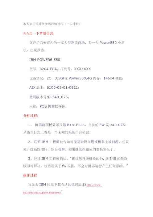
本人亲历的升级微码详细过程(一头汗啊)先介绍一下背景信息:客户是西安市内的一家大型连锁商场,有一台Power550小型机,出现报错。
IBM POWER6 550型号:8204-E8A;序列号:XXXXXXX设备情况:2C,3.5GHz Power550,4G内存,146x4硬盘; AIX版本:6100-03-01-0921;微码版本号:EL340_075;用途:POS机数据备份。
分析过程:1、机器前面板显示报错B181F126,当前的FW是340-075。
从错误日志上看是一个未知的系统平台错误。
2、联系IBM工程师被告知可能是微码问题或机器主板问题,建议先升级系统微码,然后观察,如果继续报错就的更换主板了。
3、经过IBM工程师确认,“建议您升级机器的fw到340的最新版即可解决,该错误属于fw误报,不会对机器运行产生任何影响。
”操作过程我先去IBM网站下载合适的微码版本(http://www-/support.fixcentral/)发现有2个版本:Power6 System Firmware EL340_122、Power6 System Firmware EL340_132,都下载下来,计划安装132版本。
经过和客户交流,发现前面板无HMC的连接,在服务器上没有保留与HMC连接的记录信息,OK,升级变简单了。
一、首先查看目前微码的版本AIX Version 6Copyright IBM Corporation, 1982, 2009.login: rootroot's Password:************************************************************** ****************** ** ** Welcome to AIX Version 6.1! ** ** ** Please see the README file in /usr/lpp/bos for information pertinent to * * this release of the AIX Operating System. ** ** *************************************************************** *****************Last unsuccessful login: Sun Mar 13 22:56:39 GMT+08:00 2011 on/dev/pts/1 from 192.168.20.64Last login: Sun Mar 13 23:58:53 GMT+08:00 2011 on /dev/pts/1 from 192.168.20.64# lsmcode -cThe current permanent system firmware image is SF340_075The current temporary system firmware image is SF340_075The system is currently booted from the permanent firmware image.二、将微码的RPM文件上传到/tmp/fwupdate目录中,用FTP工具的BIN模式。
Honeywell6500网卡设置(PDA掉包参考方法

Honeywell6500网卡设置(PDA掉包参考方法
6100
1、打开Power Tools下 RegEdit
HKEY_LOCAL_MACHINE\\Comm\\SDIO86861\\Parms
确认PowerMode为”0”(较少用)
保存退出后热启生效
2、冷启动(重启):按着小圆键,松开小圆键(常用);
(下面方法3和4最好不要用,恢复后有可能wifi或扫描功能消失,需要配合和开启wifi和扫描的安装包一起使用,安装包的版本可以在重启时界面有显示)
3、恢复出厂设置:按着小圆键,按一下power,松开据界面提示输入12之后按Ent回车按钮即可;
4、将Honeywell文件覆盖到我的设备中的Honeywell文件中运行AutoInstall.exe即可
小牛仪表升级文件

小牛仪表升级文件【原创版】目录1.小牛仪表简介2.小牛仪表升级文件的内容3.小牛仪表升级文件的作用4.如何使用小牛仪表升级文件5.小牛仪表升级文件的注意事项正文一、小牛仪表简介小牛仪表是一款应用于各种工程领域的智能仪表,它具有高精度、高稳定性、多功能等特点,广泛应用于石油、化工、冶金、电力等行业。
小牛仪表支持用户自定义设置,以满足不同场合的需求,为用户提供便捷的操作体验。
二、小牛仪表升级文件的内容小牛仪表升级文件主要包括以下几个方面的内容:1.功能模块升级:优化现有功能,增加新的功能,提高仪表性能。
2.数据通讯升级:优化数据传输速度,提高数据传输的稳定性,支持更多的通讯协议。
3.用户界面升级:优化用户界面设计,提供更直观、更便捷的操作体验。
4.故障诊断与保护:增加故障诊断功能,实现故障预警和自动保护,提高仪表的可靠性。
三、小牛仪表升级文件的作用小牛仪表升级文件可以带来以下好处:1.提高仪表性能:通过功能模块升级和数据通讯升级,提高仪表的精度、稳定性和响应速度。
2.提升用户体验:用户界面升级和故障诊断与保护功能,使操作更加便捷,降低故障风险。
3.适应不断变化的市场需求:通过升级文件,使小牛仪表能够适应不断变化的市场需求,满足用户日益提高的需求。
四、如何使用小牛仪表升级文件使用小牛仪表升级文件的步骤如下:1.准备升级文件:从官方网站或授权渠道下载升级文件。
2.备份数据:在升级前,建议对现有的设置数据进行备份,以防止升级过程中出现意外损失。
3.连接仪表:将小牛仪表与电脑通过 USB 或串口连接。
4.运行升级程序:打开升级文件,按照提示逐步完成升级过程。
5.完成升级:升级完成后,恢复出厂设置,然后重新设置所需的参数。
五、小牛仪表升级文件的注意事项1.确保仪表与电脑的连接正常。
2.使用官方提供的升级文件,避免使用非官方文件导致的故障。
3.在升级过程中,请勿断开连接或关闭升级程序,以免造成数据丢失或损坏。
- 1、下载文档前请自行甄别文档内容的完整性,平台不提供额外的编辑、内容补充、找答案等附加服务。
- 2、"仅部分预览"的文档,不可在线预览部分如存在完整性等问题,可反馈申请退款(可完整预览的文档不适用该条件!)。
- 3、如文档侵犯您的权益,请联系客服反馈,我们会尽快为您处理(人工客服工作时间:9:00-18:30)。
ATTO6500 微码升级文档
ATTO升级微码可通过三种方式:1.图形界面网页方式、2. FTP方式、3. 串口方式。
操作前需要进行初始配置步骤,通过QuickNAV软件完成。
默认的管理账户为root/Password(大小写敏感)。
0.配置步骤
通过网线直连工作电脑和桥设备的“management 1”管理端口。
QuickNAV软件无需安装,点击直接运行。
程序通过广播包找到ATTO 桥设备:
此时即可配置其管理IP:
重启后,即可启动浏览器,通过管理IP 访问ExpressNAV GUI :
默认的管理账户为root/Password(大小写敏感):
设备的状态信息展示:
1.通过图形界面网页方式
通过图形化界面方式升级微码较为简单,步骤如下:
1.网页登录ATTO配好的IP。
2.点击“Firmware Update”选项卡。
3.点击“浏览”,选择微码文件。
4.点击Upload按钮。
5.等待系统自动完成文件上传和更新。
6.点击“Restart”选项卡,重启设备。
系统固件升级界面如下:
原版文档中的描述如下:
Using ExpressNAV
1 If you are not already in the ExpressNAV interface, type the IP address of your FibreBridge, type in your user name and password, and click OK.
2 Click on the Firmware Update menu item on the left-hand side of the page.
3 The Firmware Update page appears. Click Browse to locate the firmware you downloaded earlier.
4 Highlight the file.
5 Click Upload.
6 Wait until a new page is displayed that shows the status of each step of the download. Result: Upon successful completion of the Flashing Firmware process, a notice will appear at the bottom of the page along with a 'Restart' button.
7 Click the Restart button to load and execute the firmware flashed in step 6 above. Result: Restarting Firmware page will appear and count down, returning you to the Status page.
8 It is highly recommended that you repeat the firmware update process
so that the backup image is replaced with up-to-date firmware.
2.通过FTP方式
通过FTP方式升级微码时,需要预先配置好ATTO的IP,并连接网线至“management 1”管理端口。
链路连接正常后,通过FTP PUT命令升级ATTO微码。
FTP在DOS下使用PUT命令方式:
1.打开cmd
2.键入ftp
3.键入open
此时需要输入希望连接的ip,即ATTO配置好的IP。
用户名使用root;
密码为Password(大小写敏感)。
4.键入put e:\fb650161.ima(微码文件路径)
5.等待系统自动完成文件上传和更新。
更新完成后,设备会自动重启。
6.重启完成后,可通过网页打开ATTO的IP,检查微码状态。
原版文档中的描述如下:
Using FTP
1 Establish an FTP link to the bridge that is to be flashed using the Ethernet-attached computer or a computer directly connected to a FibreBridge Management Port.
2 Use the PUT command to download the firmware file to the bridge. For example: PUT c:\bridge_firmware\FB6500100.IMA
3 Once the download is complete, cycle power on the FibreBridge to implement the new firmware
4 It is highly recommended that you repeat the firmware update process so that the backup image is replaced with up-to-date firmware.
3.通过串口方式
如果采用串口连接,需要设置波特率为115200bps:
Bits per second: 115200
Data Bits: 8
Parity: None
Stop Bits: 1
Flow Control: None
Terminal type: ASCII
Echo: on
通过串口升级微码时,文件传输速率较慢,仅为为10KB/s,上传一台微码
16MB需要40分钟。
不推荐此方式。
步骤如下:
1.串口console连接ATTO设备。
2.输入用户名密码:root/Password
3.键入ZMODEM RECEIVE 命令。
4.此时会自动弹出对话框选择微码文件。
选好后点击Send按钮。
5.等待系统自动完成文件上传和更新。
6.待显示“ZMODEM Transfer Complete” 后,键入firmwarerestart 设
备重启。
7.重启完成后,可通过网页打开ATTO的IP,检查微码状态。
原版文档中的描述如下:
Using the zModem command
1 Connect to the FibreBridge using a serial cable connected to the Management Serial port.
2 Load a Terminal Program such as Hyper Terminal onto the attached computer.
3 Set the terminal program and the FibreBridge for the highest possible baud rate for your terminal.
4 Turn on power to the FibreBridge.
5 Once the Ready prompt appears, type ZMODEM RECEIVE. The FibreBridge displays that it is preparing to receive a file from your terminal program.
6 On the terminal program, choose Transfer Send File.
7 In the Send File box, enter the current FibreBridge .ima file or click the browse button to find it.
8 Click Send File. Wait approximately 35 minutes for the transfer to complete.
9 The FibreBridge acknowledges receiving the file and displays a message not to interrupt power for 2 minutes wile the file is being written to flash. Once the message “ZMODEM Transfer Complete” is displayed with
the Ready prompt, type firmwarerestart.
10 It is highly recommended that you repeat the firmware update process so that the backup image is replaced with up-to-date firmware.。