【精编_推荐】ista如何安装I协议
OpenShift Assisted Installer-让安装更加简单

OpenShift Assisted Installer –让安装更加简单【文章摘要】本文介绍了如何使用OpenShift Assisted Installer 安装工具安装OpenShift集群的方法和步骤。
1 背景熟悉OpenShift安装的同学可能都知道,在过去,OpenShift有IPI(Installer Provisioned Infrastructure,也称之为全栈完全自动安装方式)和UPI(User Provisioned Infrastructure,也称之为现有基础设施安装方式)两种安装方式。
IPI直接跟底层的基础设施对接(比如国外的三大公有云、私有云里面的VMWare, Red Hat OpenStack, RHV等),安装程序直接创建需要的虚拟机,优点是安装非常简单,但缺点是并不是所有的企业都可以将底层的IaaS资源管理帐号提供给PaaS平台。
UPI的安装方式相对来说就要复杂一点,PaaS平台安装管理人员需要自己管理网络、设置负载均衡器、设置DNS、创建虚拟机和安装操作系统、创建点火文件等。
为了简化OpenShift的安装过程,尤其是提升OpenShift在裸机上面的安装体验,红帽公司推出了OpenShift Assisted Installer(OpenShift快捷安装工具,目前处于技术预览阶段)。
OpenShift Assisted Installer是专门用于简化OpenShift安装过程的一个快捷安装工具。
通过使用OpenShift Assisted Installer,用户不需要创建点火文件,也不需要单独创建一个HTTP服务器用于向外暴露CoreOS点火文件,不需要自己创建DNS服务(如果您要在集群外访问集群的API、图形化管理门户和集群内部的应用,那你还是需要DNS向外暴露这些服务;但是,安装过程本身不依赖于DNS服务),而且,安装过程也不需要一个单独的虚拟机充当bootstrap节点,从而节省了安装资源要求(实际上,bootstrap还是需要的,但是在安装过程中巧妙地借用了其中一个master 节点来实现)。
宝马ISTA-D诊断和编程使用教程
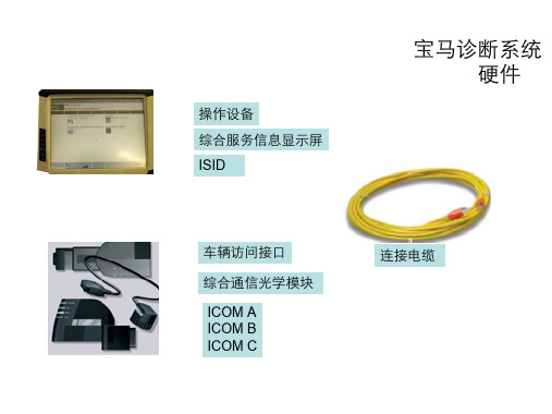
发动机 关闭发动机,将点火火钥匙转到总线端 KL 15
自自动变速箱 – 将变速箱置于位置 P – 变速箱温度低于 80°C
在带有电动机械式驻⻋车制动器的⻋车辆上启用用或拉紧驻⻋车制 动器。
用用电器 关闭所有用用电器、⻋车灯和转向信号灯。 关闭刮水水和清洗装置。确保刮水水器可自自由移动。编程期间 可能会启用用刮水水器。切勿卡住刮水水器。
X6服务功能项
03 ⻋车身身 ABL AS4162_PL4HKLINIT - 后行行李箱盖自自动操作装置初始化 ABL AS6653_TRSVCE7X-环视摄像机的校准和示示教 ABL B6130_60020-记录蓄电池更换 ABL B6135_FDM - 柔性诊断模块 ABL S5133_FHINI8770 对⻋车窗升降机进行行初始化设置 ABL S5210_NORM_SLV-E70 驾驶员侧座椅纵向调整标准化 ABL S5410_FZDINIT-对活动天窗进行行初始化设置 ABL S6100_6CAS1 - 锁止止和许可识别传感器 ABL S6100_87CASPER - 点火火钥匙:个人人化编号 ABL S6100_89003-断电命令 ABL S6121_PMG-电源管理:评估蓄电池充电状态 ABL S6131_70102 - 分析唤醒控制单元 ABL S6131_89000-分析休眠电流监控 ABL S6160_60003-对雨雨天 / 行行⻋车灯传感器进行行初始化设置 ABL S6450_PL4001 - 空调压缩机的起动保护 ABL S6450_PL4002 - 冷暖功能:重新访问空气气分配⻛风⻔门⻢马达
iHistorian 安装与使用手册

iHistorian 安装与使用手册1.i Historian安装环境设置任务概述如果准备建立iHistorian 环境,请使用以下的步骤:1.安装计算机。
2. 在每台计算机上根据需要安装Windows NT,Windows 2000,或WindowsXP 系统。
利用管理员帐户登录以便安装iHistorian。
3. 为每台计算机安装所需要的网络适配器和网络软件。
4. 仅在iHistorian 服务器节点上安装硬件密钥。
5. 如果想将权限仅向 Windows 用户开放,则在 Windows 安全中取消Guest帐号设置。
硬件要求对iHistorian 服务器来说,推荐的硬件最低要求是:● Pentium III-500 MHz 或更高配置,256 MB RAM● CD-ROM 驱动器●为网络通讯和某些I/O 驱动程序安装兼容TCP/IP 的网络适配器●屏幕最低分辨率为800 × 600●足够的磁盘空间,大约几个GB的空间给系统必需的数据归档、信息文件、缓冲文件和登录文件。
对数据采集器节点来说,推荐的硬件最低要求是:● Pentium III-500 MHz 或更高配置,128 MB RAM●2 GB 的硬盘空间来存储缓冲数据● CD-ROM 驱动器●为网络通讯和某些I/O 驱动程序安装兼容TCP/IP 的网络适配器iHistorian 服务器的大小是由采集数据的标签数量、采集标签的频率和在线数据的数量来决定的。
连接数是一个决定能同时访问系统的用户数量的指标。
首要因素是对服务器内存的要求,其次是CPU的负荷。
如果同时访问系统的客户数量和使用手册上建议的有很大出入,那么可以相应地调整服务器内存大小。
注意:由于多个应用程序在一个服务器上同时运行时,性能会有所降低。
如果可行的话,可以分别在其它单机上运行这些程序。
软件要求iHistorian 的最低软件要求:●iHistorian 服务器和数据采集器:Windows NT 4.0 SP6,Windows XP Professional,或是Windows 2000 Professional SP2。
思拓斯3i安装指南说明书

Installation GuideRevision 1.3Last revised: November 6, 2020Disclaimer:This document and its contents are not certified.Stratus 3i Installation Guide©2018-20 Appareo Systems, LLC. All Rights Reserved.Stratus 3i Installation Guide. All content within is copyrighted by Appareo Systems, LLC, and may not be reprinted without permission.The content of this guide is furnished for informational use only, is subject to change without notice, and should not be construed as a commitment by Appareo Systems, LLC. Appareo assumes no responsibility or liability for any errors or inaccuracies that may appear in the information content contained in this guide. Unauthorized replication of this guide is prohibited. Appareo, Appareo Systems, Stratus, and the Appareo logos are either registered trademarks or trademarks of Appareo Systems, LLC. MITRE is a registered trademark of the MITRE Corporation. iPad, iPhone, and iPod touch are registered trademarks of Apple Inc. App Store is a service mark of Apple Inc. All other trademarks and registered trademarks are the sole property of their respective owners.Appareo Systems, LLC, 1810 NDSU Research Circle North, Fargo, ND 58102 USA.To view the most current version of this document, go to /dealer-portal or /resources.Record of RevisionRevisionNumber Change Description Revision Date Inserted By1.0 Initial release 7/11/18 AAL1.1 Updated certification disclaimer 8/29/18 AAL1.2 Updated Stratus ES wiring diagram 1/15/19 AAL1.3 Fixed arrows in Stratus ES wiring diagram 11/6/20 AALAbout Stratus 3iStratus 3i is a portable receiver that is wired to Stratus ES/ESG. It receives auxiliary power from the transponder and also receives the ADS-B and GPS signal from the transponder’s externally-mounted antennas.Refer to the installation instructions on /resources or /dealer-portal/manuals to install Stratus ES/ESG.Supplied Components•Stratus 3i ADS-B In portable receiver•Mounting clip•9-pin D-Sub connector with mounting hardware•Power serial interface cable•BNC jack to blind mate adapter•RF interface cablePlacing Stratus 3i in the AircraftStratus 3i can be placed anywhere in the cockpit in any orientation (including sideways or upside down) as long as the Direction of Flight arrow on the top of the receiver points in the direction of flight.The provided mounting clip can be used to secure the receiver in the aircraft. The holes in the Stratus 3i mount are also compatible with many RAM mounts.Installing the Interface Cables1. Wire the 9 pin D-Sub connector to the transponder following the wiring diagram onPage 6 or 7 and the specifications below.•Maximum harness length: 3 feet•Wire gauge: 20 AWG2. Plug the Stratus 3i power serial interface cable into the 9-pin D-Sub connector. Secureusing the thumb screws.3. Install the BNC blind mate adapter in the ADSB AUX hole on the transponder backplate.4. Plug the BNC connector of the Stratus 3i RF interface cable into the BNC adapter.5. Connect the remaining end of the power serial cable into the power port of Stratus 3i,and the remaining end of the Stratus 3i RF interface cable into the ADS-B port ofStratus 3i. Secure cables as necessary.6. Power on the aircraft to make sure that Stratus 3i is receiving power. Refer to the LEDindicator statuses on Page 8.Configuring the TransponderAfter Stratus 3i has been installed, configure the transponder to allow for ADS-B In receiver information.1. Enter into configuration mode on the transponder.To enter into configuration mode: While holding the FUNC key, press and release thePWR key.2. Press FUNC or the arrow keys to navigate to the ADS-B Capability screen. Press ENT.3. Use the arrow keys to select UAT and 1090 ES. Press ENT.Turning on Stratus 3iStratus 3i automatically turns on when it receives aircraft power.If Stratus 3i is moved after being turned on, you must re-calibrate it in Stratus Horizon Pro or ForeFlight Mobile.LED Indicator Status© 2018-20 Appareo Systems, LLC. All Rights Reserved.。
IsatPhone 2 联系人同步工具安装指南说明书

同步您的联系人联系人同步工具让您可以在计算机和 IsatPhone 2 之间传输联系人信息。
此工具与 Microsoft Outlook 和 Microsoft Outlook Express 兼容。
此工具支持 Windows XP 、Windows Vista 、Windows 7 和 Windows 8。
请注意,在安装联系人同步工具以前,您需要安装 USB 驱动程序。
USB 驱动程序及指南《如何安装 USB 驱动程序》包含在 USB驱动器上。
从 USB 驱动器中选择软件 > 联系人同步工具。
Isatphone 2 联系人同步工具安装向导随之出现。
单击下一步。
安装联系人同步工具阅读并选择我接受“许可证协议”中的条款,然后单击下一步。
单击安装以开始安装进程。
注意:您可单击浏览来更改安装文件夹的位置。
安装进程结束后,请单击下一步。
注意:您可单击显示细节来显示安装详细信息。
单击完成。
安装至此完成。
注意:如果选择了运行程序,则安装一结束,该工具就会启动。
用提供的 USB 电缆将 IsatPhone 2 连接到计算机。
如果您的电话没有开机,请现在开机。
双击任务栏上的 IsatPhone 2 联系人同步工具图标来运行工具或者依次选择开始 > 程序 > IsatPhone 2 > 联系人同步工具。
选择 Microsoft Outlook 或 Microsoft Outlook Express 与电话进行同步,然后单击确定。
单击计算机应用程序上的同步图标。
联系人同步工具将依据选定的选项传输 MS Outlook 中的所有联系人。
注意:在进行同步前,可以选择同步设置。
请参阅附录。
同步您的联系人首次将电话与计算机同步时,联系人同步工具将提示您选择下列三个选项之一:• 用 Outlook 记录更换 IsatPhone 2 记录。
选择此选项将删除电话上的现有联系人,并用 Outlook联系人取而代之。
精选iscsi设置方法

精选i s c s i设置方法集团标准化办公室:[VV986T-J682P28-JP266L8-68PNN]操作系统Initiator软件安装和配置指导书1 安装环境:1.1 应用系统信息操作系统版本:IBM AIX (补丁级别:5300-02)内核版本:Initiator版本:AIX iSCSI SW (Ethernet SAN) Initiator for AIX操作系统版本:IBM AIX (补丁级别:68)内核版本:Initiator版本:AIX iSCSI SW (Ethernet SAN) Initiator for AIX2 Initiator安装过程2.1 软件安装AIX 默认安装iscsi initiator软件。
如下命令确认系统是否安装相应软件包:AIXAIXC F PCI-X 1000 Base-TX iSCSI TOE#也可执行下列命令查看,显示Available即为已安装iscsi软件。
# lsdev |grep iscsiiscsi0 Available iSCSI Protocol Device说明:如果系统没有安装iSCSI HBA卡,则软件iSCSI initiator对应为iscsi0,否则则往后递推:如果安装2块iSCSI HBA卡,则HBA对应为iscsi0和iscsi1,软件iSCSI initiator对应为iscsi2。
3 软件配置过程3.1 配置initiator名称(1)step1(进入配置界面)# smit iscsi(2)step2(选择适配器)执行smit iscsi之后,会进入如下界面,选择“iSCSI Protocol Device”Move cursor to desired item and press Enter.iSCSI Adapter(3)step3(选择适配器)确定后会进入如下界面,选择“Change / Show Characteristics of an iSCSI Protocol Device”(4)step4(选择适配器)确定之后会进入如下界面,如果没有安装HBA卡的话iscsi software intiator应该对应为iscsi0。
北信源内网安全管理系统用户使用手册

北信源内网安全管理系统用户使用手册北京北信源软件股份有限公司二〇一一年支持信息在北信源内网安全管理系统使用过程中,如您有任何疑问都可以通过访问我公司网站http://www.vrv。
com。
cn或者致电我司客服中心获得帮助和支持!热线支持:400—8188—110客户服务电话:010—62140485/86/87在您使用该产品过程中,如果有好的意见或建议的话也请联系我们的客服中心,感谢您对我公司产品的信任和支持!正文目录第一章概述 (1)特别说明 (1)产品构架 (1)应用构架 (3)第二章北信源内网安全管理系统 (5)策略中心 (5)策略管理中心 (5)网关接入认证配置 (26)阻断违规接入管理 (26)补丁分发 (26)数据查询 (26)本地注册情况统计 (27)本地设备资源统计 (27)本地设备类型统计 (27)USB标签信息查询 (27)设备信息查询 (28)审计数据查询 (29)分发数据查询 (29)非Windows操作系统设备 (30)终端管理 (30)终端管理 (30)行为控制 (30)远程协助 (31)运维监控 (31)报表管理 (32)报警管理 (32)报警数据查询 (33)本地区域报警数据统计 (33)本地报警数据汇总 (33)级联总控 (33)级联注册情况统计 (33)级联设备资源统计 (33)级联设备类型统计 (34)级联管理控制 (34)区域管理器状态查询 (35)区域扫描器状态查询 (35)级联上报数据 (36)级联报警数据 (36)系统维护 (36)系统用户分配与管理 (36)用户设置 (39)数据重整 (39)审计用户 (40)第三章北信源补丁及文件分发管理系统 (42)区域管理器补丁管理设置 (42)补丁下载配置 (42)文件分发策略配置 (43)策略中心 (43)软件分发策略 (46)其他策略 (47)补丁分发 (47)补丁自动下载分发 (48)补丁下载服务器 (48)补丁库分类 (49)补丁下载转发代理 (49)客户端补丁检测(一) (50)客户端补丁检测(二) (52)第四章北信源主机监控审计系统 (53)策略中心 (53)行为管理及审计 (53)涉密检查策略 (55)其他策略 (55)数据查询 (55)第五章北信源移动存储介质使用管理系统 (57)策略中心 (57)可移动存储管理 (57)其他策略 (57)数据查询 (57)第六章北信源网络接入控制管理系统 (59)网关接入配置认证 (59)策略中心 (60)接入认证策略 (60)其他策略 (64)环境准备方法 (64)安装RADIUS (windows IAS) (64)各厂商交换机配置 (83)Cisco2950配置方法 (83)华为3COM 3628配置 (84)锐捷RGS21配置 (87)第七章北信源接入认证网关 (89)网关接入配置认证 (89)策略中心 (90)第八章系统备份及系统升级 (92)系统数据库数据备份及还原 (92)系统组件升级 (92)区域管理器、扫描器模块升级 (92)升级网页管理平台 (93)客户端注册程序升级 (93)检查系统是否升级成功 (93)级联管理模式升级及配置 (93)附录 (95)附录(一)北信源内网安全管理系统名词注释 (95)附录(二)移动存储设备认证工具操作说明 (95)USB标签制作 (95)USB标签制作工具 (97)移动存储审计策略 (109)移动存储审计数据 (110)附录(三)主机保护工具操作说明 (110)附录(四)组态报表管理系统操作说明 (111)模版制定 (111)报表输出 (117)附录(五)报警平台操作说明 (120)设置 (120)日志查询 (123)窗口 (123)更换界面 (124)帮助 (124)附录(六)漫游功能说明 (124)漫游功能介绍 (124)漫游功能配置 (126)附录(七)IIS服务器配置说明 (130)WIN2003—32位IIS配置说明 (130)WIN2003—64位IIS配置说明 (132)WIN2008-64位IIS配置说明 (134)图目录图1—1北信源终端安全管理应用拓扑 (4)图2—1创建新策略 (5)图2—2下发策略 (6)图2—3策略控制 (6)图2-4硬件设备控制 (8)图2-5软件安装监控策略 (10)图2—6进程执行监控策略 (11)图2-7进程保护策略 (12)图2-8协议防火墙策略 (15)图2—9注册表 (16)图2-10IP与MAC绑定策略 (17)图2—11防违规外联策略 (19)图2—12违规提示 (19)图2-13文件备份路径设置 (23)图2—14注册码配置 (25)图2-15阻断违规接入控制设置 (26)图2-16本地注册情况信息 (27)图2—17本地设备资源信息 (27)图2-18本地设备类型统计 (27)图2—19软件变化信息 (29)图2—20注册日志信息 (29)图2-21交换机扫描管理配置 (32)图2—22设备信息统计图表 (33)图2—23级联设备信息 (34)图2—24级联设备系统类型统计 (34)图2-25级联管理控制 (35)图2—26下级级联区域管理器信息 (35)图2-27区域管理器状态信息 (35)图2—28区域扫描器状态信息 (35)图2—29级联上报数据 (36)图2—30系统用户列表 (36)图2-31添加系统用户界面 (37)图2—32用户管理列表 (37)图2-33终端控制权限 (38)图2-34屏幕监控权限 (38)图2—35密码初始化提示框 (39)图2—36密码初始化完成提示框 (39)图2-37修改ADMIN用户密码 (39)图2—38数据重整信息表 (40)图2-39审计用户登录 (40)图3-1区域管理器补丁管理设置 (42)图3—2分发参数设置 (43)图3-3补丁自动分发 (45)图3-4补丁下载服务器界面 (48)图3-5补丁下载服务器设置 (49)图3-6补丁代理传发支持 (50)图3-7补丁下载设置 (50)图3—8登录页面 (51)图3—9工具下载页面 (51)图3-10补丁检测中心 (52)图3—11客户端补丁漏打检测 (52)图6—2重定向配置 (60)图6—3用户添加 (60)图6—4补丁与杀毒软件认证策略 (61)图6—5接入认证策略 (62)图6—6802.1X认证界面 (63)图6-7802.1X认证界面 (63)图6-8安全检查没有通过,802。
SIMICAS产品手册

iHistorian服务器实施

附件4iHistorian服务器实施iHistorian软件是由GE Fanuc公司开发的历史数据服务器,主要特点是它的数据接口种类非常丰富,采集数据的分辨率能够到达ms级,采集的数据文件有较好的数据压缩率,稳定性和安全性也很好,是一个专业级的历史数据服务器。
iHistorian 服务器是整个辅控网络整个系统采集历史数据的中心。
iHistorian 服务器和辅控中的IFIX采集器进行通信,采集现场的数据。
iHistorian的服务器的系统组件——iHistorian数据采集器,如iFIX采集器、FIX采集器、OPC采集器、计算采集器、文件采集器、服务器到服务器采集器。
——iHistorian服务器——iHistorian管理器——iHistorian说明——iHistorian SDK开发工具一、iHistorian服务器安装辅控项目中的服务器的操作系统为windows2003 server,操作系统用户名和密码分别为administrator,hissver,设置计算机名为hissver(即为iHistorian服务器的名字)。
1、关闭计算机,连接好硬件狗并重新启动电脑2、运行iHistorian的安装光盘3、选择安装目录:d:\ihistorian4、在选择安装组件时,选择:Server,Simulation Collector,non-web Administrator,client,document,EXCEL ADD-IN,SDK,OLE DB5、完成安装,重起电脑二、iFIX采集器安装在要采集数据的iFIX上位机上安装iFIX采集器(本辅控网络是基于客户机/服务器机构,切忌把IFIX采集器安装在客户机上,否则将无法采集数据。
),目前已经安装的IFIX采集器有:#2 IFIX过程服务器。
每台IFIX采集器的安装步骤都一样,步骤如下:1、退出IFIX系统,IFIX是运行狗的话,我们关闭计算机先暂时将狗拔掉(待完全设置好之后,再将狗插上去),重新启动计算机。
如何选择正确的ISTA试验程序

1 B P a c k a g e d — P r o d u c t s w e i g h i n g Ov e r l 5 O l b ( 6 8 k g )
l C Ex t e n d e d T e s t i n g f o r I n d i v i d u a l P a c k a g e d — P r o d u c t s we i g h i n g 1 5 0 l b f 6 8 k g 1 o r L e s s l D Ex t e n d e d T e s t i n g or f I n d i v i d u a l P a c k a g e d — P r o d u c t s
C H I N A
P AC I N《
国际安全 运输 协会 ,简称 I S T A,是 一个 专注于运 输包 装 的组织 。l S T A测试程 序 定 义了 包装 应如 何发 挥 作用 来保护 内装物 。运 用 I S T A测试 程序 减少 运输 环境 中 的风
险 ,增加 包装 产 品安全 交货 的信 心 。I S T A在6 0 年前 率 先提 出了包 装性能 测试和 认证 的 概念 ,今 天他 们 的测 试程 序和 认证 计划 处 于运 输包 装的最 前 沿 。了2 0 个 运 输 测 试 程 序 和2 个 开 发程 序 , 如 何 行 试 验 的 。这 是 因 为 某些 物 流 条件 较 为 恶 劣 , 危 害 因 素超 过 了 选 择 适 合 自身包 装件 的 试验 程 序 有 时 候 给 企业 造 成 了 … 定 的 困 试验程序 的参数 ,只有提 高试验 参数才 能满 足试验 参数满 足实 扰 ,本 文 结 合I S T A的 ( ( G u i d e l i n e s f o r S e l e c t i n g a n d U s m g I S T A T e s t 际物流危害 。
[分享]FPWINGRVer.2.0松下编程软件安装使用说明
![[分享]FPWINGRVer.2.0松下编程软件安装使用说明](https://img.taocdn.com/s3/m/a7010a8bdbef5ef7ba0d4a7302768e9950e76e5b.png)
关于Control FPWIN GR (Windows版) V er.2.911版本升级天翼科技友情提示:先安装2.0,然后卸载,再安装2.9,如果电脑上已经安装有2.0及以上版本,则直接卸载原版本后安装2。
9即可。
序列号为:AFPS10823-MEW1374Control FPWIN GR Ver.2.911版本升级用于将Ver.2.0及更高的版本升级到Ver.2.911。
该文件无法单独运行。
安装该软件时,必须确保已经安装有Control FPWIN GR Ver.2.0或更高的版本。
正在使用Control FPWIN GR Ver.1的用户,请通过其他途径升级版本系统要求请确认需要安装本软件的计算机满足以下的最低配置要求。
操作系统Windows98/ Me/ 2000/ XP/ Vista/ 7硬盘可用空间大于40MB推荐CPU Pentium100MHz或更高推荐系统内存大于32MB以上(根据操作系统)推荐显示器分辨率 800 × 600 或更高推荐颜色High color16bit或更高适用PLC 松下FP全系列在下载完成后,双击该文件开始安装∙在安装过程中,请阅读使用许可协议。
继续进行安装的用户将被认为同意使用许可协议中的条件。
∙输入FPWIN GR V er.2用户注册卡中所含的安装序列号。
∙如果在Windows XP/V ista/7下安装,将出现以下信息:"您正在安装的软件没有通过Windows徽标测试,……",请选择[仍然继续]。
※如果检测到V er.2.80或更低版本,将显示信息「请卸载FPWIN GR 2」。
请在控制面板中利用「添加或删除程序」选择「FPWIN GR 2」并卸载。
卸载完成后即可安装FPWIN GR V er.2.80。
重新双击已下载的文件,然后按照画面的提示进行安装操作。
版本升级详细信息Ver.2.814到Ver.2.911∙支持FP-X0。
iStore安装手册_20120410

- 13 -
安装手册
点击“测试”按钮,测试数据库连接,提示连接成功,点击“确定” ,如下图所示:
2)
确认 Lucene 路径无误: 在目标库 Lucene 页签中, 确认 “Lucene 文件路径” 可用, 默认为 “D:\ Lucene” , 如下图,需确认:
- 14 -
安装手册
D 盘存在,如不存在可点击“选择目录”修改 “Lucene 文件路径”非系统盘分区,非磁盘阵列分区 “Lucene 文件路径”不含中文名称
- 10 -
安装手册
3. 配置环境变量
若选择安装 iStore1000 系列服务器软件,则需要配置环境变量。iStore2000 系列服务器 软件无需此项配置。 选择环境变量, 点击刷新按钮。 找到 MAM_CONFIG_CODEC 并双击。 设置变量值未 “否” , 点击确定。
- 11 -
安装手册
二、
1. 2.
软件升级 _____________________________________________________ - 43 服务器端软件升级 ______________________________________________________ - 43 客户端软件升级 ________________________________________________________ - 53 -
- 19 -
安装手册
3)
保持默认“下一步” ,直至在“发布点名称”处填写“mamweb” :
安装手册
四、 流媒体配置
下面进行 Windows 的流媒体设置: 注意:关闭媒资门户服务软件
1、创建点播发布点
1) 打开“开始菜单”“管理工具”“服务管理器”
iSignatureOFFICE用户使用手册(标准版)

iSignature For OFFICE——电子签章Version 7.2《标准版用户使用手册》尊敬的用户:您好!感谢您使用iSignature电子签章系统,请您在使用电子签章系统之前,认真阅读用户使用手册,它将帮助您在使用时,提高您的使用效率。
目录一、ISIGNATURE产品组成 (5)二、ISIGNATURE运行环境 (5)三、ISIGNATURE安装及卸载 (5)3.1系统安装 (5)3.2KEY驱动安装 (7)3.3系统卸载 (7)四电子签章使用说明 (8)4.1产品简述 (8)4.2操作说明 (9)4.2.1 签章管理 (9)4.2.2 签章查看 (11)4.2.3 密码修改 (13)4.2.4 历史记录 (14)4.2.5 操作日志 (15)4.2.6 界面显示 (16)4.2.7 文档盖章 (16)4.2.8 签章验证 (20)4.2.9 参数设置 (23)4.2.10 数字证书 (26)4.2.11版权信息 (31)五文档声明............................................................................................. 错误!未定义书签。
iSignature电子签章系统iSignature电子签章系统是将电子印章技术和电子签名技术完整的结合在一起,用来检测文档完整性和验证签章用户身份的安全产品,确保文档防伪造、防篡改、防抵赖,安全可靠。
遵循《中华人民共和国电子签名法》关于电子签名的规范,同时支持RSA算法和国密办算法,符合国家安全标准。
产品化、标准化制造标准化产品,以持续的产品升级不断满足用户电子签章的需求变化,长期享受技术进步带来的价值提升,并提供全面的售后服务支持。
安全性和合法性遵循《中华人民共和国电子签名法》关于电子签名的规范,同时支持RSA算法和国密办SSF33算法,符合国家安全标准。
AirTies Air 4921 自安装指南说明书

AT&T Smart Wi-Fi ® Extender Existing Wi-Fi GatewaySome home sizes and layoutscreate dead zones that can’t bereached by a single Wi-Fi Gateway Wi-Fi ExtenderWi-Fi Extenders provide additional coverage for those hard-to-reachareas of your homeGet started Please allow at least 10-15 minutes for installation.These instructions will guide you through the process of installing your Wi-Fi Extender. AT&T Internet service must be active and connected prior to adding your Wi-Fi Extender.In the box:Yellow Ethernet cablePower cordAirties_Guide3/17ATT170820943-2Self-installation GuideHaving trouble?• I f your Wi-Fi Extender displays a red light , it likely has a bad connection or is too far from your existing Wi-Fi Gateway. Move the Extender closer to your Wi-Fi Gateway. This provides a stronger signal.• I f your Wi-Fi Extender has both LEDs flashing green every 5 seconds, it is ready to be paired. Place your Extender close to your Gateway and press the WPS button on the front of your Wi-Fi Gateway, then the WPS button on the Extender. The 5GHz and 2.4GHz lights will flash and then turn solid green when they are successfully paired. You can then move your Extender to your final location.• P ressing the reset button on the back of the Extender with a paper clip will restore factory settings. Your Extender will need to be re-paired with your Wi-Fi Gateway by following steps 1-3.• W hen successfully paired, the 5GHz light will blink briefly every 5 seconds to indicate a successful pair. The 2.4GHz light will remain solid green. ( )• V isit /wifiextender for additional Extender support.• S ources for a weak Wi-Fi signal include microwave ovens, cordless phones and other wireless devices such as wireless speakers, baby monitors and garage door openers which can cause Wi-Fi interference.If you are experiencing service issues,check the following:Your Internet Service needs to be active.You must have working AT&T Internet servicefor your Extender to work correctly.Check your connections.Check all cables and cords to ensure theyare connected properly and securely.Power down, power up.Unplug the power cord from the back of the AT&T Wi-Fi Extender. Leave the Wi-Fi Extender unplugged for 15 seconds and plug it back in. You may need to wait up to three minutes for your Wi-Fi Extender to completely reboot.Additional informationTest your Internet connection speed Our speed test takes less than a minute toperform two key measurements (Downloadand Upload) to help you determine ifyou should take steps to improve theperformance of your online experience.Visit /speedtest .Manage your account:Available 24/7, download the myATT app at/myattapp from your mobile device.Repair center: Phone: 800.246.8464IPv6AT&T supports IPv6 across our network,equipment and devices. Visit /ipv6for more information.Accessibility support:• Alternate format guides:- Braille or large print: call 800.288.2020 and request guide number (ATT170820943-2)- Accessible tagged PDF: visit /userguides • Telephone equipment for visual and/or hearing impaired: - Phone: 877.902.6350- TTY: 800.772.2889• Repair Center: - Phone: 800.246.8464- TTY: 800.397.3172• Device Compatibility Feature: Compatible with any TTY /TDD devices with standard phone line ¿Hablas español? Por favor visita /uverseguias para ver la información en español . También puedes ver la siguiente guía: (ATT170820943-2) (FTTP-GPON CSISP) para más detalles.Need more help?Visit /support Call us at 800.288.2020and ask for “technical support.”©2017 AT&T Intellectual Property. All rights reserved. AT&T and Globe logo are registered trademarks of AT&T Intellectual Property. All other marks are the property of their respective owners.。
ISA服务器安装配置图文教程

ISA SERVER使用指南随着因特网的使用继续扩展,安全和性能也同样面临挑战。
在以前仅仅给我们提供了代理服务的软件渐渐的在我们的要求面前越来越显得苍白无力了。
怎么办我们选择了寻找新的软件以及企业上网的解决方案。
从长远来考虑,我们需要的不仅仅是一个代理软件,让企业职工能够通过这个代理访问到外面的世界,让他们感知外面的世界并且尽快的了解瞬息万变的市场。
我们不但需要主动的去了解世界,而且还需要世界来了解我们。
当然,这个时候那么安全和性能就越来越得到企业和用户的重视了。
当然更加一个迫使企业的网管们去寻找更好的代理软件的原因就是随着用户和访问量的增加代理软件的稳定性几乎成几何数积的方式递减。
我所试过的代理服务器不算少,每个代理服务器均使用了一个月以上了,但是都不是非常满意。
大致归纳起来l SYSGA TE:功能太简单,效率不是很高,稳定性还可以l WINGA TE:功能适中,速度效率都还不错,稳定性不好l WINROUTE:功能适中,速度效率基本上来说还可以,稳定性也还是不错l CCPROXY:速度不错,但是总的来说总有一些或多或少的毛病l INTERNET连接共享:功能太简单,效率非常一般,稳定性还可以还是说说我们单位的大致情况吧。
8M专线ADSL接入INTERNET,两台HP 服务器,网络中心为100M到桌面,整个企业网络为全交换式网络。
企业内部所以科室机器全部需要连接到INTERNET,科室机器大约为200台。
机房有4个,机器大约总共为200台左右。
我们需要能够随时控制哪些科室在什么时间段能够上网,并且能够对这些科室的上网带宽进行控制。
能够随时灵活的控制机房是否能够上网。
能够在企业内部建立若干个WEB 和FTP站点,并且通过这个代理服务器发布到INTERNET上,让INTERNET上的朋友对这些个资源进行访问�6�7�6�7在使用了这些代理之后,我渐渐的开始失望,难道真的没有让我满意的代理服务器吗最后,在朋友的介绍下我们使用了这款微软发布的代理服务器——Internet Security and Acceleration Server。
iTestinV20Beta安装使用说明5页

iTestin V2.0 Beta安装使用说明1 软件基本信息1.1iTestin V2.0 Beta简介∙软件版本:iTestin V2.0 Beta∙更新日期:2019-12-28∙软件大小:33.8 MB∙支持系统:Windows XP或以上版本∙终端系统支持:Andriod/iOS特别提示:系统需要安装 framework3.5或者framework3.5sp1、JDK1.6,JDK下载地址(默认安装路径为:C:\ProgramFiles\Java\jdk1.6.0):/iTestin/download/1/jdk-6-windows-i586.zip∙常见问题及反馈地址:/thread-1484-1-1.html1.2 版本主要更新内容1、新增基于界面元素录制、运行方式;2、基于界面元素录制、运行特点如下:a、一次录制可在不同终端上运行,不受分辨率、横竖屏限制;b、运行脚本不受设备输入法限制,文字自动填入;c、脚本智能延时执行,不受网络状况应影响;d、增加执行结果判定,自动判断脚本运行结果成功或失败;3、图片增加批量导出功能,无论手动或自动截图,都可打包批量下载;4、自动对比功能,可以查看录制脚本和运行脚本的情况,通过回放录制脚本情况,将两者情况比对.5、修改录制时自动截图时间间隔最少为10秒6、修复部分bug2 新增功能使用说明2.1 系统登录注:首次使用时需要输入“邀请码”,没有邀请码的用户请访问群:6018665免费获取邀请码。
2.2 录制脚本1. 开始录制设备连接成功后点击“开始录制”进入“设备录制信息”界面。
2.设置录制信息用户可自定义选择录制方式及规则。
功能说明:1)操作设备时自动截图:操作手机触发事件时自动截图2)手动截图:用户录制脚本过程中可以点击“屏幕截图“手动截图3)每隔10秒自动截图:系统会根据设定时间间隔自动截图,最小时间间隔为10秒4)基于界面元素录制:会根据点击元素记录触发事件,形成脚本;如点击了“Button”按钮;注:如果不选择该项会默认按屏幕坐标记录事件。
I-IMPACT I-IMPACT安装说明书

NOTICE• These guidelines are for couplings that require metal-to-metal bolt pad contact without a specified assembly torque.• These guidelines are for non-lubricated, zinc-electroplated carbon steel hardware only.• These guidelines are for products used on metallic piping only.Impact tools do not provide the installer with direct “wrench feel” to judge nut torque. Since some impact tools are capable of high output speed and torque, it is important to develop a familiarity with the impact tool to avoid over-shifting and/or over-torquing, which may damage or fracture the boltsor the coupling’s bolt pads during installation.Assemble couplings per the applicable Victaulic installation instructions. Scan the QR code provided for a listing of productinstallation instructions that can be downloaded on .Continue to tighten the nut(s) until the visual inspection requirements are achieved. Visual inspection of each joint is required forverification of proper assembly. For angled-bolt-pad couplings: Equal and positive or neutral offsets shall be present at the angledbolt pads.During the installation process, the installation torque shall not exceed the “Maximum Allowable Bolt Torque” values specified in the table on this page for the applicable bolt/nut size. Conditions that may result in over-shifting and/or excessive bolt torque include, but are not limited to, the following:• Improperly-Sized Impact Tool – Refer to the “Impact Tool Selection” section on the opposite side of this page.• Uneven tightening of hardware – For couplings containing two or more bolts, the nuts shall be tightened evenly by alternating sides until the visual inspection requirements for the particular coupling are achieved.• Over-shifting of the angled bolt pad – Over-shifting of an angled bolt pad results in an offset that prevents metal-to-metal contact and equal and positive or neutral offset at the opposite angled bolt pad. This occurs when the hardware is not tightened evenly by alternating sides.Attempting to tighten the hardware on one side while the other side is over-shifted is improper installation and will result in bolt torque that exceeds the “Maximum Allowable Bolt Torque” values specified in the table on this page. Continuing to tighten the hardware in an attempt to achieve metal-to-metal bolt pad contact at the other bolt pad will cause joint failure, resulting in property damage, serious personal injury, or death. For over-shifted couplings, the hardware for the angled bolt pads shall be loosened and then re-tightened to achieve equal and positive or neutral offsets at both angled bolt pads.• Out-of-specification grooved pipe end dimensions (particularly large and out-of-specification “C” diameters) – If proper visual assembly is not achieved, remove the coupling and confirm that all grooved pipe end dimensions are within Victaulic specifications. If grooved pipe end dimensions are not within Victaulic specifications, rework the pipe ends by following all instructions in the applicable pipe preparation tool’s operating and maintenance manual.• Continued tightening of nut(s) after the visual inspection requirements are achieved – DO NOT continue to tighten the nut(s) after the visual inspection requirements are achieved. Continuing to tighten the hardware after proper visual inspection requirements are achieved will cause joint failure, resulting in property damage, serious personal injury, or death. In addition, continued tightening may cause excessive stresses that compromise the long-term integrity of the bolts and may cause joint failure, resulting in property damage, serious personal injury, or death.Additional bolt torque will not provide a better installation; bolt torque that exceeds the “Maximum Allowable Bolt Torque” values specified in the table on this page could damage or fracture the bolts and/or the coupling’s bolt pads during installation.• Pinched gasket – A pinched gasket could result in the inability to achieve proper visual inspection requirements. The coupling shall be disassembled and inspected to verify that the gasket is not pinched. If the gasket is pinched, a new coupling assembly shall be used.• Coupling was not assembled per the applicable Victaulic installation instructions – Adherence to installation instructions will help to avoid the conditions covered in this document.If you suspect that any hardware has been over-torqued, the entire coupling assembly shall be replaced immediately (as indicated by a bend in the bolt, bulging of the nut at the bolt pad interface, or damage to the bolt pad, etc.).Maximum Allowable Bolt TorqueBolt/Nut Size Maximum AllowableBolt Torque*Bolt/Nut Size Maximum AllowableBolt Torque*inches Metric inches Metric5/16–15 ft-lbs5/8M16235 ft-lbs20 N•m319 N•m3/8M1055 ft-lbs3/4M20425 ft-lbs75 N•m576 N•m7/16M11100 ft-lbs7/8M22675 ft-lbs136 N•m915 N•m1/2M12135 ft-lbs1M24875 ft-lbs183 N•m1186 N•m *Maximum allowable bolt torque values have been derived from actual test dataContinued on the opposite sideI-IMPACT REV_AFor complete contact information, visit I-IMPACT 14650 REV A UPDATED 01/2021 Z000IMPACTVICTAULIC IS A REGISTERED TRADEMARK OF VICTAULIC COMPANY AND/OR ITS AFFILIATED ENTITIES IN THE UNITED STATES AND/OR OTHER COUNTRIES. © 2021 VICTAULIC COMPANY. ALL RIGHTS RESERVED.IMPACT TOOL SELECTIONAppropriate selection of an impact tool is required to ensure proper installation in accordance with the applicable coupling installation instructions. Improper impact tool selection could cause coupling mis-assembly and damage, resulting in property damage, serious personal injury, or death.To determine the suitability of an impact tool, perform trial installation assemblies with a standard socket wrench or a torque wrench. These trial coupling assemblies shall meet the visual installation requirements for the particular coupling. After visual installation requirements are achieved, measure the torque applied to each nut with a torque wrench. Using the torque value measured, select an impact tool with a torque output or torque output setting that conforms to the measured value but does not exceed the “Maximum Allowable Bolt Torque” values specified in the table on the previous page.Selection of an Impact Tool:Impact Tools with Single Output Torque – Selection of an impact tool with an output torque considerably higher than the required installation torque could result in hardware and/or coupling damage due to the possibility of hardware over-torque. Under no circumstances shall an impact tool be selected for use that has a torque output setting that exceeds the “Maximum Allowable Bolt Torque” values specified in the table on the previous page.Impact Tools with Multiple Output Torque Settings – If an impact tool with multiple output torque settings is selected, the impact tool shall have at least one torque setting that satisfies the above requirements for an “Impact Tool with Single Output Torque.”Use of impact tools with excessive output torques creates installation difficulties for the installer due to the tool’s unmanageable rotational speed and power. Using the same method above, periodically check nut torque on coupling assemblies throughout the system installation process.For safe and proper use of impact tools, always refer to the impact tool manufacturer’s operating instructions. In addition, verify that proper impactgrade sockets are being used for coupling installation.。
kubernetesistio的快速安装和使用例子
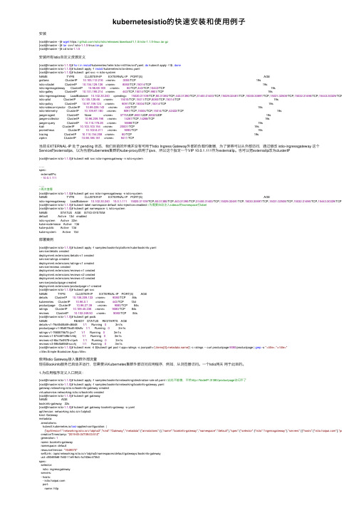
kubernetesistio的快速安装和使⽤例⼦安装[root@master ~]# wget https:///istio/istio/releases/download/1.1.5/istio-1.1.5-linux.tar.gz[root@master ~]# tar -zxvf istio-1.1.5-linux.tar.gz[root@master ~]# cd istio-1.1.5安装所有Istio⾃定义资源定义[root@master istio-1.1.5]# for i in install/kubernetes/helm/istio-init/files/crd*yaml; do kubectl apply -f $i; done[root@master istio-1.1.5]# kubectl apply -f install/kubernetes/istio-demo.yaml[root@master istio-1.1.5]# kubectl get svc -n istio-systemNAME TYPE CLUSTER-IP EXTERNAL-IP PORT(S) AGEgrafana ClusterIP 10.105.112.216 <none> 3000/TCP 19sistio-citadel ClusterIP 10.104.129.126 <none> 8060/TCP,15014/TCP 19sistio-egressgateway ClusterIP 10.96.68.169 <none> 80/TCP,443/TCP,15443/TCP 19sistio-galley ClusterIP 10.101.195.214 <none> 443/TCP,15014/TCP,9901/TCP 19sistio-ingressgateway LoadBalancer 10.102.30.240 <pending> 15020:31109/TCP,80:31380/TCP,443:31390/TCP,31400:31400/TCP,15029:32481/TCP,15030:30697/TCP,15031:32508/TCP,15032:31496/TCP,15443:30329/TCP 19s istio-pilot ClusterIP 10.105.128.66 <none> 15010/TCP,15011/TCP,8080/TCP,15014/TCP 19sistio-policy ClusterIP 10.97.159.124 <none> 9091/TCP,15004/TCP,15014/TCP 19sistio-sidecar-injector ClusterIP 10.99.226.143 <none> 443/TCP 19sistio-telemetry ClusterIP 10.109.97.180 <none> 9091/TCP,15004/TCP,15014/TCP,42422/TCP 19sjaeger-agent ClusterIP None <none> 5775/UDP,6831/UDP,6832/UDP 19sjaeger-collector ClusterIP 10.96.209.196 <none> 14267/TCP,14268/TCP 19sjaeger-query ClusterIP 10.110.178.26 <none> 16686/TCP 19skiali ClusterIP 10.103.103.154 <none> 20001/TCP 19sprometheus ClusterIP 10.102.6.211 <none> 9090/TCP 19stracing ClusterIP 10.110.154.208 <none> 80/TCP 19szipkin ClusterIP 10.98.186.181 <none> 9411/TCP当前 EXTERNAL-IP 处于 pending 状态,我们⽬前的环境并没有可⽤于Istio Ingress Gateway外部的负载均衡器,为了使得可以从外部访问,通过修改 istio-ingressgateway 这个Service的externalIps,以为当前Kubernetes集群的kube-proxy启⽤了ipvs,所以这个指定⼀个VIP 10.0.1.111作为externalIp。
IlasII安装说明

IlasII安装说明IlasII2.0 程序安装说明前期准备:安装操作系统;TCP/IP;设置正确的时区与时间;用户较多的需要扩展共享工作区。
本例服务器端操作系统为:Unix Sco openserver 5.07IlasII2.0服务器端安装1、将服务器端程序ilasII_GB_SCO.tar(即服务器端程序)以二进制的方式上传到服务器端/u目录下;方法1:通过ftp命令上传c:\> ftp 202.117.112.97 (登录到服务器上)输入服务器的帐号和口令登录到服务器:root******ftp>cd /u (到服务器上的安装目录上)ftp>lcd D:\(到客户机的当前光驱所在的根目录下)ftp>bin (设置传送数据模式为二进制)ftp>prompt (取消系统提示)ftp>put ilasII_GB_SCO.tar(将ilasII_GB_SCO.tar文件传到服务器的/u目录下) ftp>bye方法2:利用ftp软件上传利用FlashFXP等ftp软件在客户端登录服务器,然后用二进制的方式将服务器端程序上传到/u目录下2、以root登录服务器然后解包;例如:# umask 0000# cd /u# tar xvf ilasII_GB_SCO.tarumask 是指新创建文件时,那个文件具有什么权限,比如:umask=0022,当你创建一个新文件new.doc时,这个new.doc的权限就是755。
3、配置服务器端在根目录下新建/ilas文件夹,然后将/u/ilasII_GB/ilasII.ini文件复制到/ilas文件夹下。
例如:# cd /# mkdir ilas# cd ilas# cp /u/ilasII_GB/ilasII.ini /ilas编辑ilasII.ini符合如下形式:(Unix区分字母大小写)IP=202.117.112.97(服务器IP地址)PORT=27088 (使用的端口号)IlasPath=/u/ilasII_GBLocalPath=/u/ilasII_GB4、建立开机和关机文件将/u/ilasII_GB目录下的S99ilas拷入/etc/rc2.d;将K03ilas拷入/etc/rc0.d。
- 1、下载文档前请自行甄别文档内容的完整性,平台不提供额外的编辑、内容补充、找答案等附加服务。
- 2、"仅部分预览"的文档,不可在线预览部分如存在完整性等问题,可反馈申请退款(可完整预览的文档不适用该条件!)。
- 3、如文档侵犯您的权益,请联系客服反馈,我们会尽快为您处理(人工客服工作时间:9:00-18:30)。
Win Vista中如何安装IPX/SPX协
议
2008-02-06
在Windows XP或Win Server 2003计算机中的
Windows\System32文件夹中,把wshisn.dll、rtipxmib.dll和nwprovau.dll这三个文件复制到Vista中的Windows\System32文件夹中。
然后还要将Windows XP或Win Server 2003的
Windows\System32\drivers中的nwlnkipx.sys和nwlnkspx.sys文件复制到Windows Vista中的Windows\System32\drivers文件夹,最后才可以执行协议的安装。
选择看本地连接的状态:
此连接使用的项目里没有IPX/SPX兼容协议
那就点“安装”试试:
记得以前看过在WIN2003下安装NETBEUI协议的方法,似乎不能简单套用到这里来。
自己瞎捣鼓了一下,把XP里面的windows\inf目录下的netnwlnk.inf文件复制到VISTA相同目录,再把XP下
windows\system32\drivers目录下的nwlnkipx.sys和nwlnkspx.sys 这两个文件复制到VISTA相同目录。
这次点“安装”有了点动静:
但是安装过程有错误:
通过分析netnwlnk.inf文件,发现安装协议还需要如下3个文件:
把上面3个文件从XP的system32目录复制到VISTA相同目录,就可以安装IPX协议了!。
