FUF4006中文资料
UF1604CT中文资料
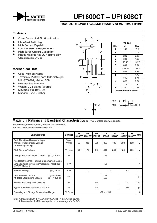
UF1600CT – UF1608CT16A ULTRAFAST GLASS PASSIVATED RECTIFIERSingle Phase, half wave, 60Hz, resistive or inductive load.For capacitive load, derate current by 20%.Characteristic SymbolUF1600CTUF1601CTUF1602CTUF1603CTUF1604CTUF1606CTUF1608CTUnitPeak Repetitive Reverse Voltage Working Peak Reverse Voltage DC Blocking Voltage V RRMV RWMV R50100200300400600800VRMS Reverse Voltage V R(RMS)3570140210280420560V Average Rectified Output Current @T C = 105°C I O16A Non-Repetitive Peak Forward Surge Current 8.3msSingle half sine-wave superimposed on rated load(JEDEC Method)I FSM125A Forward Voltage @I F = 8.0A V FM 1.0 1.3 1.7VPeak Reverse Current @T A = 25°C At Rated DC Blocking Voltage @T A = 125°C I RM10500µAReverse Recovery Time (Note 1)t rr50100nS Typical Junction Capacitance (Note 2)C j8050pF Operating and Storage Temperature Range T j, T STG-65 to +150°C Note: 1. Measured with IF = 0.5A, IR = 1.0A, IRR = 0.25A. See figure 5.2. Measured at 1.0 MHz and applied reverse voltage of 4.0V D.C.WTE50NI (Non-inductive)Ω10NIΩSet time base for 5/10ns/cm+0.5A0A -0.25A-1.0ANotes:1.Rise Time =7.0ns max.Input Impedance =1.0M ,22pF.2.Rise Time =10ns max.Input Impedance =50.ΩΩFig.5Reverse Recovery Time Characteristic and Test Circuit0225110100I ,P E A K F O R W A R D S U R G E C U R R E N T (A )F S M NUMBER OF CYCLES AT 60HzFig.3Maximum Non-Repetitive Surge Current7515010100400C ,CA P A C I T A N C E (p F )j V ,REVERSE VOLTAGE (V)Fig.4Typical Junction CapacitanceR 04850100150I ,A V E R A G E F O R W A R D C U R R E N T (A )(A V )T ,CASE TEMPERATURE (C)Fig.1Forward Current Derating CurveC °1216200.11.0101000 0.6 1.2 1.8I ,I N S T A N T A N E O U S F O R W A R D C U R R E N T (A )F V ,INSTANTANEOUS FORWARD VOLTAGE (V)Fig.2Typical Forward CharacteristicsFORDERING INFORMATIONProduct No.Package TypeShipping QuantityUF1600CT TO-22050 Units/Tube UF1601CTTO-22050 Units/TubeUF1602CT TO-220 50 Units/Tube UF1603CT TO-22050 Units/Tube UF1604CT TO-22050 Units/Tube UF1606CT TO-22050 Units/Tube UF1608CTTO-22050 Units/TubeShipping quantity given is for minimum packing quantity only. For minimum orderquantity, please consult the Sales Department.Won-Top Electronics Co., Ltd (WTE) has checked all information carefully and believes it to be correct and accurate. However, WTE cannot assume any responsibility for inaccuracies. Furthermore, this information does not give the purchaser of semiconductor devices any license under patent rights to manufacturer. WTE reserves the right to change any or all information herein without further notice.WARNING : DO NOT USE IN LIFE SUPPORT EQUIPMENT. WTE power semiconductor products are not authorized for use as critical components in life support devices or systems without the express written approval.We power your everyday.Won-Top Electronics Co., Ltd.No. 44 Yu Kang North 3rd Road, Chine Chen Dist., Kaohsiung, Taiwan Phone: 886-7-822-5408 or 886-7-822-5410Fax: 886-7-822-5417Email: sales@Internet: 。
HT66FXX中文版详细资料
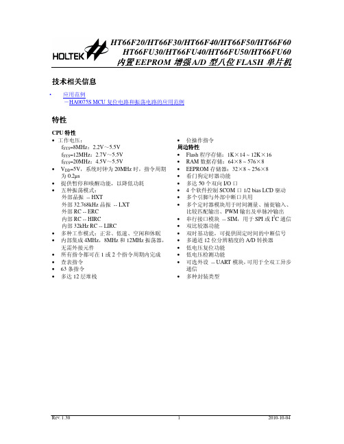
内置 EEPROM 增强 A/D 型八位 FLASH 单片机
技术相关信息
· 应用范例 -HA0075S MCU 复位电路和振荡电路的应用范例
特性
CPU 特性 • 工作电压:
这款单片机提供了丰富的 HXT、LXT、ERC、HIRC 和 LIRC 振荡器功能选项,且内建完整的系 统振荡器,无需外围元器件。其在不同工作模式之间动态切换的能力,为用户提供了一个优化单片 机操作和减少功耗的手段。
HT66FUx0 系列单片机内含 UART 模块,它可以支持诸如单片机之间的数据通信网络,低成本 PC 和外部设备间的数据连接,便携式和电池供电设备间的通信等。
HT66F30
2.2V~ 5.5V
2K×14
96×8
64×8
22
2
12-bit×8
10-bit CTM×1 10-bit ETM×1
√
HT66FU30
14
16DIP/NSOP/SSOP
—
4
20DIP/SOP/SSOP 24SKDIP/SOP/SSOP
√
24SKDIP/SOP
HT66F40
2.2V~ 5.5V
P C 1 /T P 1 B _ 1 /[S D O ]/S C O M 1 9 P C 0 /T P 1 B _ 0 /[S D I/S D A ]/S C O M 0 1 0
2 0 P A 1 /T P 1 A /A N 1 1 9 P A 2 /T C K 0 /C 0 + /A N 2 1 8 P A 3 /IN T 0 /C 0 -/A N 3 1 7 P A 4 /IN T 1 /T C K 1 /A N 4 1 6 P A 5 /C 1 X /S D O /A N 5 1 5 P A 6 /S D I/S D A /A N 6 1 4 P A 7 /S C K /S C L /A N 7 1 3 P B 5 /S C S /V R E F 1 2 P C 2 /P C K /C 1 + 1 1 P C 3 /P IN T /C 1 -
F1004中文资料
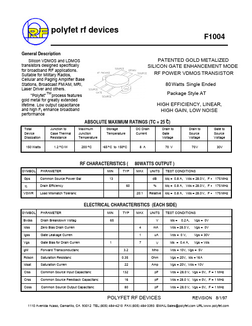
RF CHARACTERISTICS ( WATTS OUTPUT )80General DescriptionSilicon VDMOS and LDMOS transistors designed specifically for broadband RF applications. Suitable for Military Radios,Cellular and Paging Amplifier Base Stations, Broadcast FM/AM, MRI, Laser Driver and others.PATENTED GOLD METALIZED 80Watts Single Ended Package Style AT HIGH EFFICIENCY, LINEAR,ABSOLUTE MAXIMUM RATINGS (TC = 25 C)oTotal Device Junction to Case Thermal Maximum Junction StorageTemperatureDC Drain CurrentDrain to Gate Drain to Source Gate to Source 150Watts1.2Co 200-65to 1508A30VVV7070ELECTRICAL CHARACTERISTICS (EACH SIDE)SYMBOL PARAMETERMIN TYPMAXUNITS TEST CONDITIONSSYMBOL PARAMETERMIN TYPMAXUNITSTEST CONDITIONS GpsηVSWRCommon Source Power Gai Drain EfficiencyLoad Mismatch TolerancdB %Relative13600.820:1Idq = Idq = Idq = 0.80.8A,A,A,28.0Vds =V,28.0Vds =V,28.0Vds =V, F =175MHz F =175MHz F =175MHzBvdss Idss Igss Vgs gM Rdson Idsat Ciss Crss CossDrain Breakdown Voltag Zero Bias Drain Curren Gate Leakage Curren Gate Bias for Drain Curren Forward Transconductanc Saturation Resistanc Saturation CurrenCommon Source Input Capacitanc Common Source Feedback Capacitanc Common Source Output Capacitanc6541713.20.35221321680Mho Ohm Amp pF V V pF pFmA uA 0.2Ids = A,Vgs = 0V 28.0Vds =V,Vgs = 0V Vds = 0 V,Vgs = 30V 0.4Ids =A,Vgs = VdsVds = 10V,Vgs = 5V Vgs = 20V,Ids =16Vgs = 20V,Vds = 10V28.0Vds =V, Vgs = 0V, F = 1 MHz A 28.0Vds =V, Vgs = 0V, F = 1 MHz 28.0Vds =V, Vgs = 0V, F = 1 MHzPOLYFET RF DEVICES1110 Avenida Acaso, Camarillo, CA 93012 TEL:(805) 484-4210 FAX:(805) 484-3393 EMAIL:Sales@ URL:REVISION SILICON GATE ENHANCEMENT MODE RF POWER HIGH GAIN, LOW NOISE"Polyfet" process features gold metal for greatly extended lifetime. Low output capacitance and high F enhance broadband performancet TMC o Co C/Wo F1004polyfet rf devicesDissipation Resistance Temperature Voltage Voltage Voltage 8/1/97VDMOS TRANSISTORPOLYFET RF DEVICES1110 Avenida Acaso, Camarillo, CA 93012 TEL:(805) 484-4210 FAX:(805) 484-3393 EMAIL:Sales@ URL:CAPACITANCE VS VOLTAGEIV CURVE ID AND GM VS VGSS11 AND S22 SMITH CHART PACKAGE DIMENSIONS IN INCHESREVISION 8/1/97。
f16f专利分类号

f16f专利分类号一、引言F16F是专利分类系统中与摩擦、悬挂、弹簧相关的领域的编码。
摩擦、悬挂和弹簧技术在各个行业中都有广泛的应用,涉及到机械设计、汽车工程、建筑工程等领域。
本文将从这几个方面介绍F16F分类号的相关技术和应用。
二、摩擦技术摩擦技术是指利用物体之间的相对运动产生的摩擦力来实现特定的功能。
在机械设计中,摩擦技术常用于制动系统、离合器等装置中。
例如,汽车上的刹车系统就是利用摩擦力将车轮的动能转化为热能,从而实现减速和停车的功能。
此外,在工业生产中,摩擦技术也被广泛应用于传动装置、密封装置等领域。
三、悬挂技术悬挂技术是指通过合理设计和安装的悬挂系统,使物体能够在重力作用下保持平衡或者实现特定的运动。
在汽车工程中,悬挂技术是保证车辆行驶平稳的重要因素之一。
不同类型的悬挂系统可以根据特定需求进行设计,如独立悬挂、扭杆悬挂等。
此外,悬挂技术还广泛应用于建筑工程、桥梁工程等领域,以实现结构的稳定性和安全性。
四、弹簧技术弹簧技术是指利用弹性材料的变形特性来储存和释放能量的技术。
弹簧广泛应用于机械设计、建筑工程、电子设备等领域。
在机械设计中,弹簧被用于各种机械装置中,如减振器、阻尼器等。
在建筑工程中,弹簧技术被用于设计和构建高层建筑、桥梁等结构,以减少地震和风力对结构的影响。
在电子设备中,弹簧被广泛应用于键盘、开关等装置,以提供合适的手感和稳定性。
五、应用案例1. 汽车制动系统:汽车的刹车系统利用摩擦技术将车轮的动能转化为热能,从而实现减速和停车的功能。
2. 高速铁路悬挂系统:高速铁路的悬挂系统利用悬挂技术使列车在高速行驶时保持平稳,提供舒适的乘坐体验。
3. 高层建筑的减震设备:通过弹簧技术设计和构建的减震设备可以减少地震和风力对高层建筑的影响,提高建筑的安全性。
4. 机械工业中的弹簧应用:在机械工业中,弹簧被广泛应用于各种装置中,如减振器、阻尼器等,以提供合适的弹性和稳定性。
六、结论F16F专利分类号涵盖了摩擦、悬挂和弹簧等相关的技术领域。
F6系列中文使用说明书(all)

使用手册ATEQ F6th 系列F620 / F610 / F6701.04 版Reference: RF-28300D-UF6系列使用手册修订由于持续更新,本使用手册中包含的信息,本设备的功能和设计如有更改,将不另行通知。
前言/演示:定义、特点和测量原理(#673) 前面板和界面 (#676)安装/ 配件:气源 (#677)启动 (#678)配件 (#682)选配件 (#683)错误消息 (#684)以 CC/min显示结果 (#687)F610 电子连接器 (#692/1)F620 电子连接器(#692/2)F670 电子连接器(#692/7)气动连接器(#693)参数/ 特殊循环:特殊循环 (#623)服务特殊循环 (#631)程序选择 (#679)程序参数 (#680)测试循环管理 (#681)爆裂测试 (#698)程序功能:功能管理 (#601)名称 (#602)程序链接 (#603)单位 (#604)自动连接器 (#605)测试检查 (#606)ATR (#607)预充气模式和充气模式 (#608) 阀代码 & 24V辅助输出 (#609) 循环结束 (#610)迷你阀 (#611)复工界限 (#612)密封零件 (#613)N 测试 (#614)参考容积 (#615)标记 (#617)温度校正 1 (#618)峰值保持 (#620) 正负号 (#621)过滤 (#622)流量水平 (#624)非负 (#625)绝对值 (#626)显示模式 (#627) 不排气(#630)蜂鸣器 (#639)外部排气 (#655)ATF (#685)隔断 (#686)By pass (#691)配置菜单:日期 / 时间 (#635)语言 (#642)电子调压阀 (#645)调压阀控制 (#646)稳定调压阀 (#647)压力传感器自动归零 (#648)自动短归零 (#649)排气水平 (#651)RS232 (#652)安全性 (#653)I/O 配置 (#654)IN7 测试 (#656)智能键 (#688)压力单位 (#695)USB (#696)结果菜单 / USB 菜单:储存 (#638)阀服务 (#658)I/O服务 (#661)系统信息 (#665)重置参数 (#669)结果菜单 (#689)服务 / USB (#690)CAN 状态 (#697)# 601: 功能管理# 602: 名称# 603: 程序链接# 604: 单位# 605: 自动连接器# 606: 测试检查# 607: ATR# 608: 预充气模式和充气模式# 609: 阀代码 & 24V 辅助输出# 610: 循环结束# 611: 迷你阀# 612: 复工界限# 613: 密封零件# 614: N 测试# 615: 参考容积# 617: 标记# 618: 温度校准 1# 620: 峰值保持# 621: 符号取反# 622: 过滤# 623: 特殊循环# 624: 流量水平# 625: 非负# 626: 绝对值# 627: 显示模式# 631: 服务特殊循环# 635: 日期 / 时间# 638: 储存# 639 : 蜂鸣器# 642: 语言# 645: 电子调压阀# 646: 调压阀控制# 647: 稳定调压阀# 648: 压力传感器自动归零# 649: 自动短归零# 651: 排气水平# 652: RS232# 653: 安全性# 654: I/O 配置# 655 : 外部排气# 656: IN7 测试# 658: 阀服务# 661: I/O 服务# 665: 系统信息# 669: 重置参数# 673: 定义,特性和测试原理# 676: 前面板和界面# 677: 气源# 678: 启动# 679: 程序选择# 680: 程序参数 (Leak)# 681: 测试循环管理# 682: 配件# 683: 选配件# 684: 错误消息# 685: ATF# 686: 隔断# 687: 以CC/min显示结果# 688: 智能键# 689: 结果菜单# 690: 服务 / USB# 691: By pass# 692/1: F610电子连接器# 692/2: F620电子连接器# 692/7: F670 电子连接器# 693: 气动# 695: 压力单位# 696: USB# 697: CAN 状态# 698 : 爆裂测试功能管理扩展菜单功能能够进行个性化设置和添加个人选项到测试循环当中。
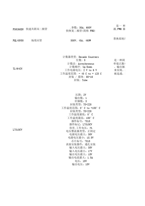
直流调速器
F30U60DN FQL40N50TL494CN L7815CV 快速共阴双二极管.参数:30A,600V快恢复二极管(简称 FRD)是一 种具源,PWM 脉宽调制器,变 频器压降:2V输出数:1针脚数:3封装类型:TO-220工作温度范围:0°C to +150°C封装类型:TO-220工作温度最低:0°C工作温度最高:150°C器件标号:7815器件标记:L7815CV容差,工作电压:4%电压整流器类型:正固定电源电压最大:30V电源电压最小:18.5V芯片标号:7815表面安装器件:通孔安装输入电压最大:35V输入电压最小:17V输出电压最大:15V输出电流最大:1.5A电压:15V输出电压:15V场效应管500V、40A、460W替换原则是:小于原管;计数器类型: Decade Counters位数: 5计数法: Asynchronous计数顺序: Up/Down工作电源电压: 2 V to 6 V工作温度范围: - 40 C to + 125 C封装 / 箱体: SO-16封装: Tube是一种固定频单端正激双管式、半桥式、。
输出脉冲的宽度是通过电来实现。
功率输出管Q1和Q2被选通,即只有在锯齿波电WDD35D 导电塑料角位移传感器WDD35D-1 长轴 轴长约33mm 外径:36.5mm, 轴径:6mm阻值:0.5-10KΩ阻值公差:±15%独立线性精度:±0.5%独立线性精度 ±0.1%理论电气转角:345°±2°分辨率:无限功率:2W(70℃)电阻温度系数(ppm/℃):<±400工作温度范围:-55℃-125℃机械转角:360°(连续)寿命:3000万次导电塑料角位其特点角位移传感器采用电阻分电刷在导轨上的移动获得输示,数值越小,精度越高。
值的精度要求,也降低了传角位移传感器结构主角位移传感器有单联、角位移传感器的输入与输出输入电压的大小来决定(如整个量种具有开关特性好,反向恢复时间短特点的半导体二极管,主要应用于开关电源,PWM 脉宽调制器,变 频器等电子电路中,作为高频整流二极管,续流二极管或阻尼二极管使用。
HEF4046BPN中文资料
HEF4046B MSI Phase-locked loop
Product specification File under Integrated Circuits, IC04 January 1995
Philips Semiconductors
Product specification
Phase-locked loop
January 1995
4
Philips Semiconductors
Product specification
Phase-locked loop
Phase comparator 2 is an edge-controlled digital memory network. It consists of four flip-flops, control gating and a 3-state output circuit comprising p and n-type drivers having a common output node. When the p-type or n-type drivers are ON, they pull the output up to VDD or down to VSS respectively. This type of phase comparator only acts on the positive-going edges of the signals at SIGNIN and COMPIN. Therefore, the duty factors of these signaபைடு நூலகம்s are not of importance. If the signal input frequency is higher than the comparator input frequency, the p-type output driver is maintained ON most of the time, and both the n and p-type drivers are OFF (3-state) the remainder of the time. If the signal input frequency is lower than the comparator input frequency, the n-type output driver is maintained ON most of the time, and both the n and p-type drivers are OFF the remainder of the time. If the signal input and comparator input frequencies are equal, but the signal input lags the comparator input in phase, the n-type output driver is maintained ON for a time corresponding to the phase difference. If the comparator input lags the signal input in phase, the p-type output driver is maintained ON for a time corresponding to the phase difference. Subsequently, the voltage at the capacitor of the low-pass filter connected to this phase comparator is adjusted until the signal and
BFP420F中文资料

NPN Silicon RF TransistorFor high gain low noise amplifiersSmallest Package 1.4 x 0.8 x 0.59mmNoise figure F = 1.1 dB at 1.8 GHzoutstanding G ma = 20 dB at 1.8 GHzTransition frequency f T = 25 GHzGold metallization for high reliabilitySIEGET 25 GHz f T - LineESD: E lectro s tatic d ischarge sensitive device, observe handling precaution!Type Marking Pin Configuration Package BFP420F AMs 1 = B 2 = E 3 = C 4 = E TSFP-4 Maximum RatingsParameter Symbol Value Unit Collector-emitter voltage V CEO 4.5V Collector-base voltage V CBO15Emitter-base voltage V EBO 1.5Collector current I C35mA Base current I B3P tot160mW Total power dissipationT S 111°C1)Junction temperature T j150°C Ambient temperature T A-65 (150)Storage temperature T stg-65 (150)Thermal ResistanceJunction - soldering point2)R thJS 240K/W1TS is measured on the emitter lead at the soldering point to the pcb2For calculation of RthJA please refer to Application Note Thermal ResistanceElectrical Characteristics at T A = 25°C, unless otherwise specified.Parameter Symbol Values Unitmin.typ.max.DC characteristicsV(BR)CEO 4.55-V Collector-emitter breakdown voltageI C = 1 mA, I B = 0I CBO--200nA Collector-base cutoff currentV CB = 5 V, I E = 0I EBO--35µA Emitter-base cutoff currentV EB = 1.5 V, I C = 0h FE5080150-DC current gainI C = 20 mA, V CE = 4 VAC characteristics (verified by random sampling)f T1825-GHz Transition frequencyI C = 30 mA, V CE = 3 V, f = 2 GHzC cb-0.150.3pF Collector-base capacitanceV CB = 2 V, f = 1 MHzC ce-0.33-Collector-emitter capacitanceV CE = 2 V, f = 1 MHzC eb-0.5-Emitter-base capacitanceV EB = 0.5 V, f = 1 MHzF- 1.1-dB Noise figureI C = 5 mA, V CE = 2 V, Z S = Z Sopt ,f = 1.8 GHzG ma-20-Power gain, maximum available 1)I C = 20 mA, V CE = 2 V, Z S = Z Sopt , Z L = Z Lopt ,f = 1.8 GHz|S21|2-17-Insertion power gainI C = 20 mA, V CE = 2 V, f = 1.8 GHz,Z S = Z L = 50IP3-24-dBm Third order intercept point at output2)I C = 20 mA, V CE = 2 V, Z S=Z L=50 ,f = 1.8 GHzP-1dB-10.5-1dB Compression point at output3)I C = 20 mA, V CE = 2 V, f = 1.8 GHz,Z S=Z L=501Gma = |S21 / S12| (k-(k2-1)1/2)2IP3 value depends on termination of all intermodulation frequency components. Termination used for this measurement is 50 from 0.1MHz to 6GHz.3DC current no input powerSPICE Parameters (Gummel-Poon Model, Berkley-SPICE 2G.6 Syntax) :Transistor Chip Data NF = 1.2432-ISE =19.049fA NR = 1.3325-ISC =0.019237fA IRB =0.72983mARC =0.10105 MJE =0.46576-VTF =0.23794V CJC =234.53fF XCJC =0.3-VJS =0.75V EG = 1.11eV TNOM300KBF =72.534-IKF =0.48731A BR =7.8287-IKR =0.69141ARB =8.5757RE =0.31111VJE =0.8051V XTF =0.42199-PTF =0deg MJC =0.30232-CJS =0F XTB =0-FC =0.73234-IS =0.20045fA VAF =28.383V NE = 2.0518-VAR =19.705V NC = 1.1724-RBM = 3.4849 CJE = 1.8063fF TF = 6.7661ps ITF =1mAVJC =0.81969V TR = 2.3249ns MJS =0-XTI =3-C'-E'-Diode Data (Berkley-SPICE 2G.6 Syntax) :IS = 3.5fA RS =10N =1.02-All parameters are ready to use, no scaling is necessaryPackage Equivalent Circuit:L BI = 0.42nH R LBI =0.15L EI = 0.26nH R LEI =0.11L CI = 0.35nH R LCI =0.13K CI-EI =-0.05-K BI-CI =-0.08-K BI-EI =0.20-L BO =0.22nH L EO =0.28nH L CO =0.22nH K BO-EO =0.10-K BO-CO =0.01-K EO-CO =0.11-C BE =34fF C BC =2fF C CE =33fFValid up to 6GHzThe TSFP-4 package has two emitter leads. To avoid high complexity of the package equivalent circuit,both leads are combined in one electrical connection.R LxI are series resistors for the inductances L xI and K xa-yb are the coupling coefficients between the inductances L xa and L yb . The referencepins for the coupled ports are B, E, C, B`, E`, C`.For examples and ready to use parameters please contact your local Infineon Technologies distributor or sales office to obtain a Infineon Technologies CD-ROM or see Internet:/silicondiscretesFor non-linear simulation:Use transistor chip parameters in Berkeley SPICE 2G.6 syntax for all simulators.If you need simulation of the reverse characteristics, add the diode with the C'-E'- diode data between collector and emitter.Simulation of package is not necessary for frequencies < 100MHz.For higher frequencies add the wiring of package equivalent circuit around the non-linear transistor and diode model.Note:This transistor is constructed in a common emitter configuration. This feature causes an additional reverse biased diode between emitter and collector, which does not effect normal operation.EHA07307CBTransistor Schematic DiagramThe common emitter configuration shows the following advantages:Higher gain because of lower emitter inductance.Power is dissipated via the grounded emitter leads, because the chip is mounted on copper emitter leadframe.Please note, that the broadest lead is the emitter lead.。
翔威电子穿心电容规格书
0.1uF
Z
7A 16VDC X7R
LC4030-7008X-100V-223M
额定电压 (DC 直流 与 AC 交流)
材料: X=X7R Y=Y5U/Y5V/Y5P N=NPO ……..
S=SL
注意:
1. 如果需方有自己的尺寸与规格要求,也可告知我们,我们接受定做。 2. 如需定做请尽量提供完整的性能参数及规格尺寸图,以便我们研发生产。 3. 免费样品:5 只(特殊产品除外)单位:毫米(MM)
L
L3
L1
D S
M L2
L
L3
L1
D2 D
D1
订货方式:
XW H C 38 22 - 50 08
L2
X -ห้องสมุดไป่ตู้100VDC - 102M
D2/ M
D1/S
公
电路式:
司
C型
名
Pi 型
称
LC 型
T型
L1
d 08=0.8mm 10=1.0mm
安装方式: H:焊接式 L:螺纹式 G:管状式
电容量 + 精度 100=10PF, K=±10% 101=100PF, M=±20% 102=1000PF,S=+50%,-20% 103=0.01uF, Z=+80%,-20% 104=0.1uF, P=+100%,-0% 105=1uF,……
C
100pF
Z
7A 50VDC SL
LC4030-7008S-50V-101Z
4
M3-0.5 0.8 30.3 7 3 8.3 C
100pF
Z
7A 100VDC SL
LC4030-7008X-50V-103Z
UF4007;UF4004;UF4001;UF4003;UF4006;中文规格书,Datasheet资料

©2005 Fairchild Semiconductor UF4001 - UF4007 Rev. C3UF4001 - UF4007 Fast RectifiersUF4001 - UF4007 Fast RectifiersUF4001 - UF4007 Rev. C3TRADEMARKSThe following are registered and unregistered trademarks Fairchild Semiconductor owns or is authorized to use and is not intended to be an exhaustive list of all such trademarks.3UF4001 - UF4007 Rev. C3UF4001 - UF4007 Fast RectifiersDISCLAIMERFAIRCHILD SEMICONDUCTOR RESERVES THE RIGHT TO MAKE CHANGES WITHOUT FURTHER NOTICE TO ANY PRODUCTS HEREIN TO IMPROVE RELIABILITY, FUNCTION OR DESIGN. FAIRCHILD DOES NOT ASSUME ANY LIABILITY ARISING OUT OF THE APPLICATION OR USE OF ANY PRODUCT OR CIRCUIT DESCRIBED HEREIN; NEITHER DOES IT CONVEY ANY LICENSE UNDER ITS PATENT RIGHTS, NOR THE RIGHTS OF OTHERS.LIFE SUPPORT POLICYFAIRCHILD’S PRODUCTS ARE NOT AUTHORIZED FOR USE AS CRITICAL COMPONENTS IN LIFE SUPPORT DEVICES OR SYSTEMS WITHOUT THE EXPRESS WRITTEN APPROVAL OF FAIRCHILD SEMICONDUCTOR CORPORATION.As used herein:1. Life support devices or systems are devices or systems which,(a) are intended for surgical implant into the body, or (b) support or sustain life, or (c) whose failure to perform when properly used in accordance with instructions for use provided in the labeling,can be reasonably expected to result in significant injury to the user.2. A critical component is any component of a life support device or system whose failure to perform can be reasonably expected to cause the failure of the life support device or system, or to affect its safety or effectiveness.PRODUCT STATUS DEFINITIONS Definition of TermsDatasheet Identification Product Status DefinitionAdvance InformationFormative or In Design This datasheet contains the design specifications for product development. Specifications may change in any manner without notice.PreliminaryFirst ProductionThis datasheet contains preliminary data, andsupplementary data will be published at a later date.Fairchild Semiconductor reserves the right to make changes at any time without notice in order to improve design.No Identification Needed Full ProductionThis datasheet contains final specifications. Fairchild Semiconductor reserves the right to make changes at any time without notice in order to improve design.Obsolete Not In ProductionThis datasheet contains specifications on a product that has been discontinued by Fairchild semiconductor.The datasheet is printed for reference information only.FAST ®FASTr™FPS™FRFET™GlobalOptoisolator™GTO™HiSeC™I 2C™i-Lo ™ImpliedDisconnect™IntelliMAX™ISOPLANAR™LittleFET™MICROCOUPLER™MicroFET™MicroPak™MICROWIRE™MSX™MSXPro™OCX™OCXPro™OPTOLOGIC ®OPTOPLANAR™PACMAN™POP™Power247™PowerEdge™PowerSaver™PowerTrench ®QFET ®QS™QT Optoelectronics™Quiet Series™RapidConfigure™RapidConnect™µSerDes™SILENT SWITCHER ®SMART START™SPM™Stealth™SuperFET™SuperSOT™-3SuperSOT™-6SuperSOT™-8SyncFET™TinyLogic ®TINYOPTO™TruTranslation™UHC™UltraFET ®UniFET™VCX™A CEx™ActiveArray™Bottomless™CoolFET™CROSSVOLT ™DOME™EcoSPARK™E 2CMOS™EnSigna™FACT™FACT Quiet Series™Across the board. Around the world.™The Power Franchise ®Programmable Active Droop™Rev. I15分销商库存信息:FAIRCHILDUF4007UF4004UF4001 UF4003UF4006UF4005。
UF4001-UF4007

UF4001 – UF40071.0A ULTRAFAST RECOVERY RECTIFIERSingle Phase, half wave, 60Hz, resistive or inductive load.For capacitive load, derate current by 20%.Characteristic SymbolUF4001UF4002UF4003UF4004UF4005UF4006UF4007UnitPeak Repetitive Reverse Voltage Working Peak Reverse Voltage DC Blocking Voltage V RRMV RWMV R501002004006008001000VRMS Reverse Voltage V R(RMS)3570140280420560700V Average Rectified Output Current(Note 1) @T A = 55°CI O 1.0ANon-Repetitive Peak Forward Surge Current8.3ms Single half sine-wave superimposed onrated load (JEDEC Method)I FSM30A Forward Voltage @I F = 1.0A V FM 1.0 1.3 1.7VPeak Reverse Current @T A = 25°C At Rated DC Blocking Voltage @T A = 100°C I RM5.0100µAReverse Recovery Time (Note 2)t rr5075nS Typical Junction Capacitance (Note 3)C j2010pF Operating Temperature Range T j-65 to +125°C Storage Temperature Range T STG-65 to +150°C*Glass passivated forms are available upon requestNote: 1. Leads maintained at ambient temperature at a distance of 9.5mm from the case2. Measured with IF = 0.5A, IR = 1.0A, IRR = 0.25A. See figure 5.3. Measured at 1.0 MHz and applied reverse voltage of4.0V D.C.WTE0.010.11.0100.20.40.60.81.01.21.4I ,I N S T A N T A N E O U S F O R W A R D C U R R E N T (A )F V ,INSTANTANEOUS FORWARD VOLTAGE (V)Fig.2Typical Forward CharacteristicsF1020300110100I ,P E A K F O R W A R D S U R G E C UR R E N T (A )F S M NUMBER OF CYCLES AT 60Hz Fig.3PeakForward Surge Current50NI (Non-inductive)Ω10NIΩSet time base for 5/10ns/cm+0.5A0A -0.25A-1.0ANotes:1.Rise Time =7.0ns max.Input Impedance =1.0M ,22pF.2.Rise Time =10ns max.Input Impedance =50.ΩΩFig.5Reverse Recovery Time Characteristic and Test Circuit110100110100C ,C A P A C I T A N C E (pF )j V ,REVERSE VOLTAGE (V)Fig.4Typical Junction CapacitanceR 00.250.500.751.00255075100125150175I ,A V E R A G E F W D R E C T I F I E D C U R R E N T (A )(A V )T ,AMBIENT TEMPERATURE (C)Fig.1Forward CurrentDerating CurveA °ORDERING INFORMATIONProduct No.!Package TypeShipping QuantityUF4001-T3DO-415000/Tape & Reel UF4001-TB DO-415000/Tape & Box UF4001DO-411000 Units/Box UF4002-T3DO-415000/Tape & Reel UF4002-TB DO-415000/Tape & Box UF4002DO-411000 Units/Box UF4003-T3DO-415000/Tape & Reel UF4003-TB DO-415000/Tape & Box UF4003DO-411000 Units/Box UF4004-T3DO-415000/Tape & Reel UF4004-TB DO-415000/Tape & Box UF4004DO-411000 Units/Box UF4005-T3DO-415000/Tape & Reel UF4005-TB DO-415000/Tape & Box UF4005DO-411000 Units/Box UF4006-T3DO-415000/Tape & Reel UF4006-TB DO-415000/Tape & Box UF4006DO-411000 Units/Box UF4007-T3DO-415000/Tape & Reel UF4007-TB DO-415000/Tape & Box UF4007DO-411000 Units/BoxProducts listed in bold are WTE Preferred devices.!T3 suffix refers to a 13” reel. TB suffix refers to Ammo Pack.Shipping quantity given is for minimum packing quantity only. For minimum order quantity, please consult the Sales Department.Won-Top Electronics Co., Ltd (WTE) has checked all information carefully and believes it to be correct and accurate. However, WTE cannot assume any responsibility for inaccuracies. Furthermore, this information does not give the purchaser of semiconductor devices any license under patent rights to manufacturer. WTE reserves the right to change any or all information herein without further notice.WARNING : DO NOT USE IN LIFE SUPPORT EQUIPMENT. WTE power semiconductor products are not authorized for use as critical components in life support devices or systems without the express written approval.We power your everyday.Won-Top Electronics Co., Ltd.No. 44 Yu Kang North 3rd Road, Chine Chen Dist., Kaohsiung, Taiwan Phone: 886-7-822-5408 or 886-7-822-5410Fax: 886-7-822-5417Email: sales@Internet: 。
WFF4N60中文资料

102
Operation in This Area is Limited by R DS(on)
101
100 µs
1 ms
10 ms
100
DC
10-1 10-2
100
※ Notes :
1. TC = 25 oC 2. TJ = 150 oC 3. Single Pulse
101
102
IS
Continuous Source Current
Integral Reverse p-n Junction
ISM
Pulsed Source Current
Diode in the MOSFET
VSD
Diode Forward Voltage
IS =4.0A, VGS =0V
trr
Reverse Recovery Time
8
VDS = 480V
6
4
2
※ Note : ID = 4.0 A
0
0
4
8
12
16
20
QG, Total Gate Charge [nC]
Figure 6. Gate Charge Characteristics
元器件交易网
Typical Characteristics (Continued)
Symbol 1. Gate{
{ 2. Drain
●
◀▲
● ●
{ 3. Source
TO-220F
123
Absolute Maximum Ratings *( Drain current limited by junction temperature)
UF640中文资料

UNISONIC TECHNOLOGIES CO., LTDUF640MOSFET18 A, 200 V, 0.18 OHM,N-CHANNEL POWER MOSFETDESCRIPTIONThese kinds of n-channel power mos field effect transistor have low conduction power loss, high input impedance, and high switching speed, Linear Transfer Characteristics, so can be use in a variety of power conversion applications.The UF640 suitable for resonant and PWM converter topologies.FEATURES* R DS(ON) =0.18Ω@V GS = 10V.* Ultra Low gate charge (typical 43nC)* Low reverse transfer capacitance (C RSS = typical 100 pF) * Fast switching capability * Avalanche energy specified* Improved dv/dt capability, high ruggednessSYMBOL1.GateTO-22011TO-220F*Pb-free plating product number: UF640LORDERING INFORMATIONOrder Number Pin AssignmentNormal Lead Free Plating Package 1 2 3 PackingUF640-TA3-T UF640L-TA3-T TO-220 G D S Tube UF640-TF3-T UF640L-TF3-T TO-220F G D S TubeABSOLUTE MAXIMUM RATING (T C = 25 , unless otherwise specified)PARAMETER SYMBOL RATINGS UNITDrain Source Voltage V DSS 200 V Drain Gate Voltage (R GS = 20k Ω) V DGR 200 V Gate Source Voltage V GSS ±20 VT C = 25 18 AContinuous Drain Current T C = 100 I D11 APulsed Drain Current (Note ) I DM 72 A Single Pulse Avalanche Energy Rating (Note ) E AS 580 mJ Maximum Power Dissipation 125 WDissipation Derating Factor P D1.0W/ Junction Temperature T J +150 Storage Temperature T STG -55 ~ +150 Note Absolute maximum ratings are those values beyond which the device could be permanently damaged.Absolute maximum ratings are stress ratings only and functional device operation is not implied.THERMAL DATAPARAMETER SYMBOL MIN TYP MAX UNITThermal Resistance, Channel to Ambient θJA 62 °C/W Thermal Resistance, Channel to Case θJC 1 °C/WELECTRICAL CHARACTERISTICS (T C = 25, unless otherwise specified)PARAMETER SYMBOL TEST CONDITIONS MIN TYP MAX UNIT Drain Source Breakdown Voltage BV DSS I D = 250µA, V GS = 0V 200 V Gate Threshold Voltage V GS(THR)V GS = V DS , I D = 250µA 2 4 VV DS = Rated BV DSS , V GS = 0V 25 µADrain-Source Leakage Current I DSS V DS = 0.8 x Rated BV DSS , V GS = 0V,T J = 125250µAOn-State Drain Current I D(ON) V DS >I D(ON) x R DS(ON)MAX, V GS = 10V 18 A Gate-Source Leakage Current I GSS V GS = ±20V ±100nA Drain-Source On Resistance R DS(ON)I D = 10A, V GS = 10V 0.14 0.18Ω Forward Transconductance g FS V DS ≥ 10V, I D = 11A 6.7 10 S Input Capacitance C ISS 1275 pFOutput Capacitance C OSS 400 pFReverse Transfer Capacitance C RSSV DS = 25V, V GS = 0V, f = 1MHz 100 pF Total Gate Charge(Gate to Source + Gate to Drain) Q G(TOT) 43 64 nCGate-Source Charge Q GS 8 nC Gate-Drain “Miller” Charge Q GDV GS = 10V, I D ≈ 18A, V DS = 0.8 x Rated BV DSS Gate Charge isEssentially Independent of Operating Temperature I G(REF) =1.5mA22 nC Turn-On Delay Time t D(ON) 13 21 ns Rise Time t R 50 77 nsTurn-Off Delay Time t D(OFF) 46 68 nsFall Time t FV DD = 100V, I D ≈ 18A, R GS = 9.1Ω, R L = 5.4Ω, MOSFET Switching Times are Essentially Independent ofOperating Temperature35 54 nsELECTRICAL CHARACTERISTICS(Cont.)2. Repetitive Rating: Pulse width limited by maximum junction temperature. See Transient Thermal Impedancecurve.3. L = 3.37mH, V DD = 50V, R G = 25Ω, peak I AS = 18A, starting T J = 25 .TEST CIRCUITV DSV DDASFigure 1A. Unclamped Energy Test CircuitFigure 1B. Unclamped Energy WaveformspBVFigure 2A. Switching Time Test CircuitFigure 2B. Resistive Switching WaveformsR LVDDV DSSAMPLING RESISTORSAMPLING RESISTOR 0Figure 3A. Gate Charge Test Circuit V DDFigure 3B. Gate Charge WaveformsTYPICAL CHARACTERISTICSSaturation CharacteristicsDrain to Source Voltage , V DS (V)D r a i n C u r re n t , I D (A )Drain to Source On Resistance v s. GateVoltage And Drain CurrentDrain Current , I D (A)D r a i n t o S o u r c e o n R e s i s t a n c e R D S (O N ) (Ω)。
FUF5404中文资料

Maximum Ratings, according to IEC publication No. 134
FUF 5400 FUF 5401 FUF 5402 FUF 5404 FUF 5406 FUF 5407 FUF 5408
VRRM Peak Recurrent reverse voltage (V)
3A
IFRM Recurrent peak forward surge current
IFSM
8.3 ms. peak forward surge current
(Jedec Method)
30 A 150 A
trr
Max. reverse recovery time from IF = 0.5 A ; IR = 1 A ; IRR = 0.25 A
0.01
0.6 0.8
1
1.2 1.4 1.6
V , instantaneous forward voltage (V) F
TYPICAL JUNCTION CAPACITANCE 100
50
10
5 1
T j = 25 ºC f = 1 MHz
5 10
50 100
VR, reverse voltage (V)
FORWARD CURRENT DERATING CURVE 5
10 mm. - 10 mm.
4
3
2
1
0 0 25 50 75 100 125 150 175 Tamb, ambient temperature (ºC) MAXIMUM NON REPETITIVE PEAK FORWARD SURGE CURRENT
元器件交易网
FUF5400........ FUF5408
UF4000中文资料

Data Sheet 2629, Rev. AUF4001 THRU UF4007Reverse Voltage - 50 to 1000 Volts Forward Current - 1.0 AmpereCase : JEDEC DO-41 molded plastic bodyTerminals : Plated axial leads, solderable per MIL-STD-750,Method 2026Polarity : Color band denotes cathode end Mounting Position : AnyWeight :0.012 ounce, 0.33 gramsThe plastic package carries Underwriters Laboratory Flammability Classification 94V-0Ultra fast switching for high efficiency Low reverse leakageHigh forward surge current capability High temperature soldering guaranteed:250 C/10 seconds,0.375”(9.5mm) lead length,5 lbs. (2.3kg) tensionFEATURESMECHANICAL DATAMAXIMUM RATINGS AND ELECTRICAL CHARACTERISTICSRatings at 25 C ambient temperature unless otherwise specified.Single phase half-wave 60Hz,resistive or inductive load,for capacitive load current derate by 20%.Note:1.Reverse recovery condition I F =0.5A,IR =1.0A,Irr=0.25A2.Measured at 1MHz and applied reverse voltage of 4.0V D.C.3.Thermal resistance from junction to ambient at 0.375” (9.5mm)lead length,P.C.B. mountedDimensions in inches and (millimeters)DO-41Data Sheet 2629, Rev. ARATINGS AND CHARACTERISTIC CURVES UF4001 THRU UF40071.00.80.60.40.20.1 1.0 10 1000.01 0.1 1 10 1001001010.1REVERSE VOLTAGE,VOLTSt,PULSE DURATION,sec.FIG. 6-TYPICAL TRANSIENT THERMAL IMPEDANCEFIG. 3-TYPICAL INSTANTANEOUS FORWARDCHARACTERISTICSNUMBER OF CYCLES AT 60 HzFIG. 2-MAXIMUM NON-REPETITIVE PEAK FORWARDFIG. 1- FORWARD CURRENT DERATING CURVE0.010.1120101001010.10.01PERCENT OF PEAK REVERSE VOLTAGE,%FIG. 4-TYPICAL REVERSE CHARACTERISTICSAMBIENT TEMPERATURE, CSENSITRONSEMICONDUCTORTECHNICAL DATADISCLAIMER:1- The information given herein, including the specifications and dimensions, is subject to change without prior notice to improve product characteristics. Before ordering, purchasers are advised to contact the Sensitron Semiconductor sales department for the latest version of the datasheet(s).2- In cases where extremely high reliability is required (such as use in nuclear power control, aerospace and aviation, traffic equipment, medical equipment, and safety equipment), safety should be ensured by using semiconductor devices that feature assured safety or by means of users’ fail-safe precautions or other arrangement.3- In no event shall Sensitron Semiconductor be liable for any damages that may result from an accident or any other cause during operation of the user’s units according to the datasheet(s). Sensitron Semiconductor assumes no responsibility for any intellectual property claims or any other problems that may result from applications of information, products or circuits described in the datasheets.4- In no event shall Sensitron Semiconductor be liable for any failure in a semiconductor device or any secondary damage resulting from use at a value exceeding the absolute maximum rating.5- No license is granted by the datasheet(s) under any patents or other rights of any third party or Sensitron Semiconductor.6- The datasheet(s) may not be reproduced or duplicated, in any form, in whole or part, without the expressed written permission of Sensitron Semiconductor.7- The products (technologies) described in the datasheet(s) are not to be provided to any party whose purpose in their application will hinder maintenance of international peace and safety nor are they to be applied to that purpose by their direct purchasers or any third party. When exporting these products (technologies), the necessary procedures are to be taken in accordance with related laws and regulations.。
402轴结构体文档

402轴结构体文档(原创版)目录1.400f 保养手册概述2.保养手册的内容3.保养手册的重要性4.如何使用保养手册5.保养手册的益处正文400f 保养手册概述400f 保养手册是一本针对 400f 设备的保养指南,它包含了设备的维护、保养和维修等方面的详细信息。
这本手册的目的是帮助用户延长设备的使用寿命,保证设备的高效运行,并减少因设备故障而产生的额外费用。
400f 保养手册包含了以下几个方面的内容:1.设备概述:介绍了 400f 设备的基本信息,包括设备的主要部件、工作原理等。
2.保养周期:列出了设备各个部件的保养周期,包括日常保养、每周保养、每月保养等。
3.保养方法:详细介绍了设备各个部件的保养方法,包括清洁、润滑、紧固等。
4.故障排除:列出了设备可能出现的故障及其解决方法。
5.维修指南:提供了设备维修的基本步骤和注意事项。
保养手册的重要性400f 保养手册对于设备的正常运行和延长使用寿命具有重要意义。
通过按照手册中的保养周期和方法进行保养,可以有效减少设备故障的发生,提高设备的工作效率,节省维修费用。
在使用 400f 保养手册时,应遵循以下几个步骤:1.首先,阅读手册中的设备概述部分,了解设备的基本信息。
2.根据保养周期表,制定设备的保养计划。
3.按照手册中的保养方法,进行设备的日常、每周、每月保养。
4.如遇设备故障,查阅故障排除部分,进行自行排查和维修。
5.如设备需要大修,可参考维修指南部分进行操作。
保养手册的益处通过使用 400f 保养手册,用户可以获得以下益处:1.延长设备使用寿命:按照手册中的保养方法进行维护,可以有效延长设备的使用寿命。
2.提高设备工作效率:设备的保养可以确保其处于良好的工作状态,从而提高工作效率。
3.节省维修费用:通过手册中的故障排除和维修指南,用户可以自行解决一些设备故障,节省维修费用。
4.保障操作安全:手册中包含了设备的安全操作规程,遵循这些规程可以确保操作安全。
方形40uf四针电容 -回复

方形40uf四针电容-回复方形40uf四针电容是一种常见的电子元件,广泛应用于电子设备中。
本文将逐步回答与该电容相关的问题,包括其定义、结构、工作原理、应用领域以及注意事项等。
一、什么是方形40uf四针电容?方形40uf四针电容是一种电容器,具有四个引线,常用于电子设备的电路中。
40uf表示其电容量大小,单位为微法(μF),用于描述电容器的存储电荷能力。
由于电容器可储存电荷,因此在电路中具有对电流的导通和屏蔽等功能。
二、方形40uf四针电容的结构方形40uf四针电容通常有一个方形外壳,外壳材料一般为塑料或金属。
内部结构包括两个金属导电板(也称为电极板),中间通过一层绝缘材料隔开。
电极板附加引线通过设在外壳两侧的安装孔连接,形成四个引线结构。
三、方形40uf四针电容的工作原理方形40uf四针电容通过存储电荷来实现其功能。
当电容器两个引线连接到电路中后,它会从电源中吸收电荷,并将其存储在电容器内的电极板上。
电路中的电流会随着电容器的充电和放电而改变,从而实现对电流的导通和控制。
四、方形40uf四针电容的应用领域方形40uf四针电容广泛应用于各种电子设备中,特别是滤波器、解码器、电源电路、通信设备以及音频放大器等。
在滤波器中,方形40uf四针电容可以用于削弱或滤除某些特定频率的信号,提高信号的质量和稳定性。
在音频放大器中,它可以用于提高音频信号的质量,并减少噪声的干扰。
五、方形40uf四针电容的注意事项1.安装时需要避免直接触摸电容器,以免发生电击危险。
2. 在使用或存储电容器时,不能超过其额定电压范围,否则可能导致电容器损坏。
3. 方形40uf四针电容应储存于干燥、无腐蚀性气体的环境中,以防止电容器的内部元件受到污染或损坏。
4. 使用方形40uf四针电容时,需要遵守相关的安全操作规程,以确保人身安全和设备的正常工作。
总结:方形40uf四针电容是一种常见的电子元件,具有存储电荷、导通电流和屏蔽等功能。
ADF4106
说明:ADF4106频率合成器,可用于实现无线接收器和发射器的上变频和下变频部分实现本地振荡器。
它由一个低噪声数字相位频率检测器(PFD),一个精密电荷泵,一个可编程参考分频器,可编程A计数器和B计数器,以及一个双模预置分频器(P/P+1)。
一个(6位)计数器和B(13位)计数器结合的双模预置分频器(P/P+1),实施一个N分频器(N=BP+A)。
此外,14位的参考计数器(R计数器)允许在PFD输入端选择REFIN频率。
可以实现一个完整的锁相环(PLL),如果使用合成器与外部环路滤波器和压控振荡器(VCO)。
其极高的带宽意味着倍频可以消除在许多高频系统,简化了系统结构和降低成本。
特点:6.0GHz带宽2.7V至3.3V电源供应独立的电荷泵电源(VP)允许在3V系统中扩展调节电压可编程双模预置分频器8/9,16/17,32/33,64/65可编程电荷泵电流可编程antibacklash脉冲宽度3线串行接口,模拟和数字锁定检测硬件和软件掉电模式应用:宽带无线接入卫星系统的仪器仪表无线局域网的无线射频基站功能框图:规格:AVDD=DVDD=3V10%,AVDD≤VP≤5.5V时,AGND=DGND=CPGND=0V时,RSET=5.1k俚模榈250賒Bm时,TA=TMAXTMIN,TA=TMAXTMIN,除非另有说明。
注:1工作温度范围(B版)是-40C至+85C2的B芯片规格为典型值3这是最大的CMOS计数器的工作频率。
应选择预分频值,以确保分为RF输入频率小于这个值4AVDD=DVDD=3V5AC耦合确保AVDD/2偏压6由设计保证。
样本测试,以确保遵守7TA=25C;AVDD=DVDD=3V,P=16;RFIN=900兆赫8TA=25℃9TA=25C;AVDD=DVDD=3V,P=32;RFIN=6.0千兆赫10TA=25℃;AVDD=DVDD=3.3V,R=16383,A=63,B=891,P=32;RFIN=6.0千兆赫。
- 1、下载文档前请自行甄别文档内容的完整性,平台不提供额外的编辑、内容补充、找答案等附加服务。
- 2、"仅部分预览"的文档,不可在线预览部分如存在完整性等问题,可反馈申请退款(可完整预览的文档不适用该条件!)。
- 3、如文档侵犯您的权益,请联系客服反馈,我们会尽快为您处理(人工客服工作时间:9:00-18:30)。
50 35 50
100 70 100
200 140 200
400
600
800 560 800
1000 700 1000
280 420 400 600 1A 10 A 30 A
Max. reverse recovery time from IF = 0.5 A ; IR = 1 A ; IRR = 0.25 A Typical Junction Capacitance at 1 MHz and reverse voltaje of 4VDC Operating temperature range Storage temperature range Maximum non repetitive peak reverse avalanche energy. IR = 0.5A ; TJ = 25 ºC Max. forward voltage drop at IF = 1 A Max. reverse current at VRRM at 25 ºC Max. thermal resistance ( l = 10 mm.)
Maximum Ratings, according to IEC publication No. 134
FUF 4001 FUF 4002 FUF 4003 FUF 4004 FUF 4005 FUF 4006 FUF 4007
VRRM VRMS VDC IF(AV) IFRM IFSM trr Cj Tj Tstg E RSM
FUF4005 FUF4007
0.4 0.1 0.2
T j = 25 ºC
0 0 25 50 75 100 125 150 175 Tamb, ambient temperature (ºC)
0.01 0.6 0.8 1 1.2 1.4 1.6 VF , instantaneous forward voltage (V)
ห้องสมุดไป่ตู้
• Glass Passivated Junction • High current capability • The plastic material carries U/L recognition 94 V-0 • Terminals: Axial Leads • Polarity: Color band denotes cathode
®
5 +0.2 -0 58.5 ± 0.5
Mounting instructions 1. Min. distance from body to soldering point, 4 mm. 2. Max. solder temperature, 350 °C. 3. Max. soldering time, 3.5 sec. 4. Do not bend lead at a point closer than 2 mm. to the body.
MAXIMUM NON REPETITIVE PEAK FORWARD SURGE CURRENT 50
TYPICAL JUNCTION CAPACITANCE 70 60
40 50 30
T j = 25C f = 1 MHz
40 30 20
20
10 10 0 1 2 4 6 10 20 40 100 Number of cycles at 60 Hz. 0 0.1 0.5 1 2 5 10 50 100 VR , reverse voltage (V)
FUF4000 Rating And Characteristic Curves
FORWARD CURRENT DERATING CURVE 1
10 mm. - 10 mm. FUF4001 thru FUF4004
TYPICAL FORWARD CHARACTERISTIC 10
0.8 1 0.6
50 ns 15 pF – 65 to + 150 °C – 65 to + 150 °C 20 mJ
75 ns
Electrical Characteristics at Tamb = 25 °C
VF IR Rthj-a 1.3 V 5µA 50 °C/W 1.7 V
元器件交易网
Peak Recurrent reverse voltage (V) Maximum RMS voltage Maximum DC blocking voltage Forward current at Tamb = 55 °C Recurrent peak forward surge current 8.3 ms. peak forward surge current
元器件交易网
FUF4001........ FUF4007
1 Amp. Glass Passivated Ultrafast Recovery Rectifier
Dimensions in mm. DO-41 (Plastic)
Voltage 50 to 1000 V.
Current 1 A at 55 ºC.
