020 LED
led封装技术的发展趋势与市场应用

LED封装技术的发展趋势与市场应用一、引言LED(Light Emitting Diode,发光二极管)作为一种高效节能的光源,近年来在照明、电子显示、汽车照明等领域得到了广泛的应用。
而LED封装技术作为LED产业链中至关重要的一环,其发展趋势和市场应用也备受关注。
本文将从LED封装技术的发展趋势和市场应用两个方面进行全面评估和探讨,以期能够更深入地理解LED封装技术在未来的发展方向和商业应用。
二、LED封装技术的发展趋势1. 现状分析目前,LED封装技术已经实现了从无封装、普通封装到高端封装的跨越式发展。
从最早期的DIP封装到SMD封装再到COB、CSP等封装技术的不断涌现,LED封装技术在尺寸、亮度、热散发、可靠性等方面均取得了长足的进步。
然而,随着LED行业的不断发展,LED封装技术面临着更多的挑战和机遇。
2. 发展趋势(1)微型化:LED产品呈现微型化趋势,封装技术将更加注重尺寸的缩小和功率密度的提升,以满足高端应用对于体积和功率的需求;(2)模块化:LED封装将更加趋向模块化,不同功能的模块将能够实现快速组装,提高生产效率和灵活性;(3)多功能化:LED封装不再单一追求亮度,而是结合色温调节、光学设计等多功能需求,为各种场景提供定制化解决方案;(4)智能化:LED封装产品将更加智能化,融合无线通信、传感器等功能,为智慧照明、智能家居等领域提供更多可能。
三、LED封装技术在市场的应用1. 现状分析LED封装技术的不断创新和发展,推动了LED应用市场的蓬勃发展。
从室内照明到户外照明,从电视显示到汽车照明,LED封装技术的应用场景越来越广泛。
LED封装产品的差异化和个性化需求也在市场中愈发显现。
2. 应用市场(1)照明领域:LED封装产品在室内照明、商业照明、景观照明等各个领域均有广泛应用,高亮度、高色温、调光、色彩丰富等特点成为LED封装产品在照明市场的竞争优势;(2)显示领域:LED封装产品在电视、手机、显示屏等领域的应用也日益普及,高对比度、高刷新率、柔性化等成为LED封装产品的市场吸引点;(3)汽车领域:LED封装产品在汽车大灯、尾灯、仪表盘等照明系统中的应用也越来越受欢迎,高可靠性、防水防尘、多功能化等成为市场需求的重点。
最新ED020侧发光蓝光灯珠规格书460-463.5nm
LED020侧发光蓝光规格书产品型号:YT-020B 蓝光适用于: 顺向电流 IF=20mA目录1.特性2.应用范围3.产品外观尺寸4.最大绝对标称值5.光电特性参数6.典型光电参数曲线7.编带规格8.包装方式9.BIN级范围10.可靠度实验项目及条件11.使用注意事项1、特性:1.1 封装尺寸:3.8x1.0x0.6mm1.2发光颜色:蓝色1.3胶体颜色:无色透明1.4焊接方式:回流焊1.5符合RoHS 标准2、应用范围:2.1手机按键2.2一般应用3、成品外观尺寸:备注:1.所有尺寸均以mm 为单位4、最大绝对标称值(环境温度=25℃):5.光电特性参数(环境温度=25℃):备注:1.亮度偏差:±5% 2.电压偏差:±0.033.主波长偏差:±16.典型光电参数曲线40IF(mA)IF(mA)80 604020Vf(V)0.020.0 40.0 60.0 80.0 Ta(°C)100.0 FIG.1 FORWARD CURRENT VS. FORWARD VOLTAGE.FIG.2 MAXIMUM FORWARD DC CURRENT VSAMBIENT TEMPERATURE(Tjmax=105 °C)Half PowerWL=150nmI (RELATIVE LUMINOUS INTENSITY)5.04.03.02.01.00.0 0.020.040.060.080.0If(mA) 100.0400600 FIG.3 RELATIVE LUMINOUS INTENSITY VS. FORWARD CURRENTFIG.4 RELATIVE LUMINOUS INTENSITY VS. WAVELENGTH.50% Power Angle:120°0°le(%)100%80%60%40%20%-90°-60°-30° 0 30° 60°0%90°FIG.5 FAR FIELD PATTERN7. 编带规格:(单位:mm )包装数量 1000-4000pcs/卷8.包装方式:(单位:mm)9.BIN 级范围正向电压VF(公差:±0.05V):20MA测试亮度IV(公差:±5%):10.可靠度实验项目及条件:可靠度实验不合格判定标准:IV:衰减超过 30%VF:变化超过 20%备注:1、同一项实验结果的测试需在 2 个小时之内完成;2、测试必须在每项实验完成后、材料恢复正常环境条件下才能进行.11.使用注意事项11.1焊接SMD LED 灌封胶较软,外力易损坏发光面及塑料壳,焊接时要轻拿轻放。
LED封装培训资料(看封装制程_有图片)

LED电流与亮度关系
LED在可使用的电流范围内﹐发光亮度随着电流的增加而增强
LED电流与温度关系
LED在特定的电流下可承受的环境温度
温度对LED的影响
随着温度的升高,led光强会衰减,波长会变长,电压会下降 在超高亮度和功率型LED器件及阵列组件中,不合理的结构设计将导致P/N结的温度升
SMD吸嘴选择
客户在 SMT 时直径尽量选择比 LED(胶体)发光面大的吸嘴防止吸嘴下压高度设置的不当造 成对 LED 内部金线的损坏
吸嘴高度:在正面发光二极管 SMT 时吸嘴下压高度是引响 LED 质量的直接因素, 因吸嘴下压 太深会压迫 LED 胶体导至内部金线变形或断裂,造成 LED 不亮或闪烁﹔LED的焊盘同PCB焊盘 刚好接触最好
LED优点
寿命长,一般大于10万小时 功耗小,亮度高,可与集成电路匹配 体积小,重量轻,可封装成各种类型的显示器 坚固耐用,不怕震动 多色显示,可实现彩色显示 工作温度稳定性好 响应时间快,一般为毫微秒(ns)级 冷光,不是热光源 当与光电晶体结合时可以作为低噪音光开关 电压低,可以用太阳能电池作电源,并易与集成电路相匹配
LED在多颗使用时要求发光亮度及颜色的一致性﹐因此对于驱动方式及驱动条件要充分了解﹐正常 的条件下我司保証20MA(LAMP部分的材料)或是30mA(食人鱼部分)分光的颜色和亮度的一致性
要获得均匀的亮度和颜色﹐贵司使用电流请与我司分光电流条件一致﹐使用时避免多包混用﹐以免 造成电性﹑亮度﹐颜色的差异
﹐60秒以内进行 说明︰焊接温度或时间控制不当可能引起灯体的透镜变形或者灯芯内部开路导致死灯
SMD焊接条件
人工焊接 1、烙铁及锡丝选择:建议使用 25-30W 的烙铁或者调温烙铁及选用<0.5mm的锡丝 2、温度调整:根据不同的 PCB 板将温度调整到 280-350℃ 3、焊接时间:整个焊接时问控制在3-5 S,在焊接过程中因胶体处在高温情况下, 不 可按压胶体,不可给LED引脚施加压力让锡丝自然溶化与引脚结合
深圳市格天光电 LED 产品使用说明
SMD LED 是表面粘着型发光二极管,适用于SMT制程,由以下几个部分组成(如图1): a. 朔料外壳 b. 透光胶体 c. 粘接 d. 芯片 e. 芯片电极连接线 F .引脚
深圳市格天光电有限公司
ShenZhen GeTian Opto-Electronics CO.,LTD1
LED 产品使用须知
目录
第1节:产品概述---------------------P2 第2节:SMD装运与储存----------------P4 第3节:关于静电---------------------P5-P6 第4节:材料的拿取方式---------------P7 第5节:焊接-------------------------P8-P9 第6节:清洁-------------------------P9 第7节:电性测试及应用---------------P10 第8节:电源驱动---------------------P10 第9节:点亮防护---------------------P10 第10节:应用成品安装与防护----------P11
器件是正向或反向状态;静电电流均会在十分之一微秒时间通过人体和器件电阻释热击穿。 3.4.静电的产生
项次
类别
发生时机
在日常生活中,任何两个不同材质的物体接触后再分离,即可产生静电,而
1
摩擦
产生静电的最常见的方法,就是摩擦生电。材料的绝缘性越好,越容易摩擦
地址:深圳市宝安区西乡镇宝田三路东56栋6楼
洋光盛光盛-侧发光020RGB六脚贴片LED规格书

目录List1.特性Features2.成品外观尺寸Packing Dimensions3.应用范围Applications4.最大绝对标称值Absolute Maximum Ratings5.光电特性参数Electrical and Optical Characteristics6.光电特性曲线Optoelectronics Characteristics Typical Curves7.编带规格Tapping Specifications8.包装方式Way of Packing9.包装规格及标签说明Packing Specifications and Label10.信赖度测试及条件Reliability Test11.使用注意事项Points for Attention●特性 Features:1. Emitted Color : Double or Three color.发光颜色:红绿蓝2. Lens Appearance: Colorless transparent.胶体颜色:透明色3. Suitable for all SMT assembly methods.适合所有SMT组装方法4. Compatible with infrared and vapor phase reflow solder process.适合回流焊及红外焊5. Compatible with automatic chip mounter.适合自动贴片设备6. Meet ROHS standard.符合ROHS标准●成品外观尺寸 Packing Dimensions:备注NOTES:1.All dimensions are in millimeters.单位:毫米2.T olerance is ±0.10mm (0.004”) un less otherwise specified.无明确标注下,公差均为±0.10mm●光电特性曲线 Typical Electro-Optical Characteristics Curves信赖度实验不合格判定标准 Reliability test is not qualified standard : ·IV :衰减超过30%IV: attenuation above 30%·VF :变化超过20%VF: changes above 20%●使用注意事项 Points for Attention1.焊接 SolderingSMD LED 封装胶较软,外力易损坏放光面及塑料壳,焊接时要轻拿轻放。
吸嘴、金亿达吸嘴介绍

吸嘴:
LED吸嘴、金亿达吸嘴是自动固晶机取放和搬动LED晶片的一种工具,由于取放和搬动晶粒是靠真空的作用二种材料生产的较多,一是金亿达钨钢,另一种是金亿达高速钢下过完成,因此金亿达吸嘴也称为真空吸嘴真空吸头。
根据金亿达吸嘴的形状不同我们可以将吸嘴分为:JT形吸嘴、VR柱形吸嘴、长方形吸嘴、双孔吸嘴;根据固晶时贴片的晶片形状大小可以称小功率吸嘴(一般针对6mil-14mil晶片)和长方形吸嘴(一般有8*12mil、10*23mil和12*24mil晶片等)或大功率吸嘴(有24mil、35mil、38mil、40mil、45mil等);根据吸嘴的材料不同,也可以称作材料的吸嘴,如:钨钢吸嘴、陶瓷吸嘴、电木吸嘴、橡胶吸嘴等。
JT形吸嘴是指金亿达吸嘴的前端有个阶梯形状的连接过程到吸嘴头部,阶梯形状用是能够让吸嘴在工作时将晶片放入杯孔较小的LED支架杯中,而不会将支架的杯壁碰到。
VR柱形吸嘴是指吸嘴的头部像根小柱子一样直伸出来,一般伸出的尺寸为VR=0.8mm,柱形的直径约为12mil。
因此它非常适合生产LED支架较深的LED晶片,目前做010LED、020LED和一些侧面发光的LED产品就必须用到它了。
长方形吸嘴是指吸嘴的头部呈长方形状,一般适合生产8*12mil、10*23mil和12*24mil等规格的长方形晶片,对针长方形LED晶片的不同,长方形吸嘴也必须做到不同的规格与之匹配。
双孔吸嘴是专门针对表面是双电极的LED晶片而生产的,它避免了电极表层带来的压伤,为焊线工站的PR图像识别带来了便利。
做什么样的晶片就得选择相适应的LED吸嘴和金亿达吸嘴,这样才能使吸嘴与LED晶片匹配。
JT形吸嘴 VR柱形吸嘴
电木吸嘴 KEDLED吸嘴
橡胶吸嘴。
MARL 202系列灯泡替换型LED说明书

202SERIESBULB REPLACEMENT LED2015/863/EURoHS FEATURESBENEFITS•T1Midget Flange SX3s Base •Water clear lens •Flat topped LED•Centre contact Anode as standard •Range of LED colour options •Range of voltage options•Direct replacement for standard bulb fitting •Water clear lens gives clear “off”state•Flat topping gives even illumination of large lens areas •Direct replacement for standard polarity installations •No colour filter required•Manufactured with internal resistor •Outstanding reliability202-301-20-38Red 5-62033640-30to +85-40to +85202-325-20-38Yellow 5-620401590-30to +85-40to +85202-324-20-38Green 5-6201010525-30to +85-40to +85202-934-20-38Blue5-620225471-30to +85-40to +85202-991-20-38Warm White 5-620Call See Below -30to +85-40to +85202-998-20-38Cool White 5-6201194See Below -30to +85-40to +85202-301-21-38Red 122033640-30to +85-40to +85202-325-21-38Yellow 1220401590-30to +85-40to +85202-324-21-38Green 12201010525-30to +85-40to +85202-934-21-38Blue1220225471-30to +85-40to +85202-991-21-38Warm White 1220Call See Below -30to +85-40to +85202-998-21-38Cool White 12201194See Below -30to +85-40to +85202-301-23-38Red 24-281527640-30to +85-40to +85202-325-23-38Yellow 24-2815308590-30to +85-40to +85202-324-23-38Green 24-2815830525-30to +85-40to +85202-934-23-38Blue24-2815175471-30to +85-40to +85202-991-23-38Warm White 24-2815Call See Below -30to +85-40to +85202-998-23-38Cool White 24-2815932See Below -30to +85-40to +85202-301-24-38Red 481218640-30to +85-40to +85202-325-24-38Yellow 4812208590-30to +85-40to +85202-324-24-38Green 4812615525-30to +85-40to +85202-934-24-38Blue4812125471-30to +85-40to +85202-991-24-38Warm White 4812Call See Below -30to +85-40to +85202-998-24-38Cool White4812648See Below -30to +85-40to +85X 0.4330.4330.4400.440Y0.4030.4150.4230.411X 0.2960.2830.3300.330Y0.2760.3050.3600.318NOTESIntensities (lv)and colour shades of white (X-Y co-ordinates)may vary between LEDs within a batch.Additional LED Colours,Voltage Options and Reverse Polarity options available for semi-custom projects.Please contact our Sales Team.All LED components are supplied in anti-static packaging.*Characteristics at Ta =25°C.For operating temperature derating graphs,please refer to sheet 2.TECHNICAL DATATECHNICAL DRAWINGDE-RATING GRAPHSDESIGN CONSIDERATIONSSingle-Chip LEDsAll devices feature water clear high intensity LEDs as standard.In devices where discrete LEDs are used,the single chip LED devices have been modified by the removal of the domed portion of the encapsulation (flat-topped)to provide even illumination of switches and annunciators.Non flat topped versions are also available.Flat-topping does not apply to devices using surface-mounted device (SMD)LEDs.Product EvaluationFilament replacement LEDs have been specifically designed to meet the primary objective of providing improved reliability.As this product range is suitable for both new-build and retro-fit,(sometimes in very old systems),a wide range of illuminated push button switches and lamp holders can be encountered.Due to subjectivity,evaluation of the LED type is recommended,(samples of all standard models are available).Care should be taken to correctlysimulate operating ambient light conditions to ensure that the correct device has been selected to maximise viewing characteristics such as viewing angle,colour compatibility and on/off contrast ratio.Electro-Static Discharge (ESD)Build up of electro-static discharge occurs in many situations involving people moving and handling products.The range of possible situations is very diverse but voltage levels as high as several thousand volts can and do arise in many individual situations.When an operator charged up to these levels handles a static sensitive device,there is a very probable likelihood that the device will be irreversibly damaged.It is essential that precautions are taken at all stages during manufacture and assembly of these products.Although LEDs were never considered to be static sensitive devices,changes in manufacturing technology and materials used to produce higher intensity products over a large range of the wavelength spectrum have changed this.Marl has an approved system of ESD control from goods in,through production and into final packing and despatch.Marl recommend all users of LED based products follow the current BSI guidelines for protection of electronic devices from electrostatic phenomena.Voltage,Current and TemperatureThe forward voltage /current value of an LED is dependent upon the ambient temperature of the environment in which it is operated.Therefore,care must be taken to operate the LED at the correct voltage /current values,depending upon the ambient temperature.Marl should be contacted if the device is to be operated outside the temperature range specified.Marl accept no liability for any product that is operated outside the stated voltage or temperature range.Weight (g):0.3Dimensions in mm (typical).Not to scale.Green dot on base of product signifies centre contact cathode -ve.Colour sleeve on product denotes LED colour.Series Lamp Base StyleMetric Equivalent Max.Power Dissipation202T1Sub Midget Flange SX3s 3360mmmW。
020侧发光贴片led灯珠参数

020侧发光贴片led灯珠参数
根据您提供的信息,020侧发光贴片LED灯珠的参数可能如下:
- 尺寸:020(即长2mm,宽0.8mm)
- 发光颜色:多种可选,如红色、黄色、蓝色、绿色、白色等
- 亮度:通常以毫瓦(mW)或流明(lm)为单位来表示
- 电压:通常以伏特(V)为单位,常用的值为3.0V、3.2V、3.5V等
- 电流:通常以毫安(mA)为单位,常用的值为20mA、
30mA等
- 角度:指LED发光的方向范围,可能为120度或更小的角度- 工作温度:通常以摄氏度(℃)为单位,可能为-20℃至+80℃或其他范围
- 良好的瞬态和稳态响应特性
- 耐用性:具有高抗震、抗振动性能
- 长寿命:通常以小时(h)为单位,可能为10000小时、50000小时等
- 导通方式:可能为共阳极(CA)或共阴极(CC)等
需要注意的是,具体的参数可能因不同品牌、型号的LED灯
珠而有所不同。
建议您在购买时查看相关产品规格表以获得准确的参数信息。
0201led工作参数

0201led工作参数一、引言本文将介绍0201尺寸L ED的基本工作参数,包括电气特性、光学特性和热特性。
二、电气特性1.工作电压0201尺寸LE D的工作电压一般为2.8-3.4V。
在这个电压范围内,L E D可以正常发光和工作。
2.推荐电流0201尺寸LE D的推荐工作电流为5-20mA。
过大的电流会导致L ED发热过高,降低寿命;过小的电流则会影响L ED的亮度。
3.正向电压0201尺寸LE D的正向电压一般为1.8-2.2V。
在这个电压下,L ED会正常导通,形成电流通路,从而发出光线。
三、光学特性1.发光亮度0201尺寸LE D的发光亮度一般在100-500m cd之间。
发光亮度越高,L E D的亮度也就越高。
发光亮度的单位是毫坎德拉(m cd)。
2.视角0201尺寸LE D的视角一般为120度。
视角决定了L ED的发光范围,较大的视角可以让LE D的光线更加广泛地照射到周围。
3.波长0201尺寸LE D发出的光线波长可以根据需要进行调整,常见的波长有红色(620-630nm)、绿色(520-525n m)和蓝色(465-470n m)等。
四、热特性1.热阻0201尺寸LE D的热阻一般在100-300℃/W之间。
热阻代表了LE D散热的能力,数值越小表示LE D能更好地散热,温度上升越少。
2.工作温度0201尺寸LE D的工作温度一般在-40℃到+85℃之间。
在这个温度范围内,L ED能够正常工作而不受到温度的影响。
五、结论综上所述,0201尺寸L ED的工作参数包括电气特性、光学特性和热特性。
熟悉这些参数可以帮助我们更好地设计和应用LE D产品,提高其性能和可靠性。
以上就是关于0201le d工作参数的相关内容,希望本文对读者有所帮助。
(字数:283)。
led020侧发光中英文规格书
东莞市荧月电子科技有限公司020贴片超亮白色发光二极管020 SMD Hyper White Top LED产品型号 Model NO.YT020CW0S1版次 REV NO.:V01版文件编号Document NO.:YT-C030001日期 DATE :2015.3.1020 SMD Hyper White Top LED 020贴片超亮白色发光二极管Features 特征•Package Size :3.8 (L) ×0.95(W) × 0.6 (T) mm 封装尺寸:3.8(长) ×0.95 (宽) ×0.6 (厚) mm •Silicone Packed 采用硅胶封装•Super long lifetime 超长寿命 •Anti UV防紫外线•White colors are available in(2200K -12000K) 可供白光(2200K-12000K) •High CRI products 高显色性产品•Wide viewing angle (2θ1/2=120°) 宽角度 (2θ1/2=120°)Applications •产品应用•Indoor lighting : Fluorescent lamp, tube •室内照明:日光灯管、灯条•Commercial illumination and displays : •商业照明显示:广告字、广告灯箱 Advertising words, light box•LCD Backlighting •LCD 背光源•Decorative lighting : light strip •装饰照明:柔性灯条 •Automotive interior auxiliary lighting•Other illumination and displays •其它照明和显示类O OTop View 顶视OOOPart No. Description 产品型号说明Packaging Description 包装编号说明:电压代码:Bin Range of Forward Voltage 亮度代码:Bin Range of Luminous Intensity 显指代码:Bin Range of RA BIN 位代码:Bin Range of bin 色温代码:Bin Range of Color CCT 型号代码:Type of LED公司代码:Yingyue -electronic CO.,LTDColor Bin Limit 色度代码;(at I F = 30 mA, T a = 25 OC )Color Bin色坐标-电特性曲线图PACKAGE OUTLINE外形尺寸(Units: mm)(mm)一、PRECAUTONS IN USE LED/使用LED注意事项;LED Soldering condition/ LED焊接条件;1:烙铁焊接:烙铁最高30W尖端温度不超过300℃;焊接时不超过3秒;焊接位至少离胶体2毫米。
LZC-00WW00 高亮度温暖白色LED发光二极管说明书

LZC-00WW00LZC-C0WW00High Luminous Flux DensityWarm White LED EmitterLZC-00WW00Key Features▪High Luminous Flux Density 12-die Warm White LED▪More than 40 Watt power dissipation capability▪Ultra-small foot print – 9.0mm x 9.0mm▪Very low Thermal Resistance (0.7°C/W)▪Surface mount ceramic package with integrated glass lens▪Spatial color uniformity across radiation pattern▪Excellent Color Rendering Index▪JEDEC Level 1 for Moisture Sensitivity Level▪Lead (Pb) free and RoHS compliant▪Reflow solderable (up to 6 cycles)▪Emitter available with several MCPCB options▪Recommend use with LL-3T08 lens family to provide standard beam patterns suitable for general lighting applicationsTypical Applications▪General lighting▪Down lighting▪Architectural lighting▪Street lighting▪Stage and Studio lighting▪Refrigeration lighting▪Portable lightingDescriptionThe LZC-series 12-die White LED emitter has an electrical input power dissipation capability of more than 40 Watt electrical power in an extremely small package. With a small 9.0mm x 9.0mm ultra-small footprint, this package provides exceptional luminous flux density. LED Engin’s patent-pending thermally insulated phosphor layer provides a spatial color uniformity across the radiation pattern and a consistent CCT over time and temperature. The high quality materials used in the package are chosen to minimize stresses and optimize light output which results in superior reliability and lumen maintenance. The robust product design thrives inProduct NomenclatureThe LZ Series part number designation is defined as follows:L Z A – B C D E F GWhere:A –designates the number of LED die in the package (―C‖ for 12-die)B –designates the package level (―0‖ for Emi tter or other number for MCPC options)C – designates the radiation pattern (―0‖ for Lambertian)D andE – designate the color (―W W‖ for Warm White: 2600 K < CCT < 3800 K)Luminous Flux BinsTable 1:Bin CodeMinimumLuminous Flux(ΦV)@ I F = 700mA[1,2](lm)MaximumLuminous Flux (ΦV)@ I F = 700mA[1,2](lm)TypicalLuminous Flux (ΦV)@ I F = 1000mA[2](lm)X 1,085 1,357 1,540Y 1,357 1,696 1,920Z 1,696 2,120 2,400Notes for Table 1:1. Luminous flux performance guaranteed within published operating conditions. LedEngin maintains a tolerance of± 10% on flux measurements.2. Luminous Flux typical value is for all 12 LED dice operating concurrently at rated current.Forward Voltage BinsTable 2:Bin CodeMinimumForward Voltage (V F)@ I F = 700mA[1,2](V)MaximumForward Voltage (V F)@ I F = 700mA[1,2](V)0 38.40 49.92Notes for Table 2:1. LedEngin maintains a tolerance of ± 0.04V for forward voltage measurements.2. Forward Voltage is binned with 12 LED dice connected in series. The actual LED is configured with two strings of 6dice in series.Warm White Chromaticity Groups0.330.350.370.390.410.430.450.470.360.380.400.420.440.460.480.50xyFigure 1: Standard Chromaticity Groups plotted on excerpt from the CIE 1931 (2°) x-y Chromaticity Diagram.Coordinates are listed below in Table 3.Warm White Chromaticity CoordinatesTable 3:IPC/JEDEC Moisture Sensitivity LevelTable 4 - IPC/JEDEC J-STD-20.1 MSL Classification:Soak RequirementsFloor Life Standard AcceleratedLevel Time Conditions Time (hrs) Conditions Time (hrs) Conditions1 unlimited ≤ 30°C/85% RH168+5/-085°C/85% RHn/a n/aNotes for Table 4:1. The standard soak time includes a default value of 24 hours for semiconductor manufacturer’s exposure time(MET) between bake and bag and includes the maximum time allowed out of the bag at the distributor’s facility.Average Lumen Maintenance ProjectionsLumen maintenance generally describes the ability of a lamp to retain its output over time. The useful lifetime for solid state lighting devices (Power LEDs) is also defined as Lumen Maintenance, with the percentage of the original light output remaining at a defined time period. Based on long-term WHTOL testing, LedEngin projects that the LZ Series will deliver, on average, 70% Lumen Maintenance at 100,000 hours of operation at a forward current of700 mA per die. This projection is based on constant current operation with junction temperature maintained at or below 125°C.Typical Radiation PatternFigure 2: Typical representative spatial radiation pattern.Absolute Maximum RatingsTable 5:Parameter Symbol Value Unit DC Forward Current at T jmax=130C[1]I F1200 mA DC Forward Current at T jmax=150C[1]I F1000 mA Peak Pulsed Forward Current[2]I FP1500 mA Reverse Voltage V R See Note 3 V Storage Temperature T stg-40 ~ +150 °C Junction Temperature T J150 °C Soldering Temperature[4]T sol260 °C Allowable Reflow Cycles 6ESD Sensitivity[5]> 8,000 V HBM Class 3B JESD22-A114-DNotes for Table 5:1. Maximum DC forward current (per die) is determined by the overall thermal resistance and ambient temperature.Follow the curves in Figure 10 for current derating.2: Pulse forward current conditions: Pulse Widt h ≤ 10msec and Duty cycle ≤ 10%.3. LEDs are not designed to be reverse biased.4. Solder conditions per JEDEC 020D. See Reflow Soldering Profile Figure5.5. LedEngin recommends taking reasonable precautions towards possible ESD damages and handling the LZC-00WW00in an electrostatic protected area (EPA). An EPA may be adequately protected by ESD controls as outlined inANSI/ESD S6.1.Optical Characteristics @ T C = 25°CTable 6:Parameter Symbol Typical Unit Luminous Flux (@ I F = 700mA)[1]ΦV1400 lmLuminous Flux (@ I F = 1000mA)[1]ΦV1800 lmLuminous Efficacy (@ I F = 350mA) 65 lm/WCorrelated Color Temperature[2]CCT 3100 KChromaticity Coordinates x,y 0.430, 0.402Color Rendering Index (CRI / R9) R a / R985 / 30Viewing Angle[3]2Θ1/2110 DegreesNotes for Table 6:1. Luminous flux typical value is for all 12 LED dice operating concurrently at rated current.2. Viewing Angle is the off-axis angle from emitter centerline where the luminous intensity is ½ of the peak value.Electrical Characteristics @ T C = 25°CTable 7:Parameter Symbol Typical Unit Forward Voltage (@ I F = 700mA)[1]V F42.0 VForward Voltage (@ I F = 1000mA)[1]V F43.8 VTemperature Coefficientof Forward Voltage[1]ΔV F/ΔT J-33.6 mV/°CThermal Resistance(Junction to Case)RΘJ-C0.7 °C/WNotes for Table 7:1. Forward Voltage is binned with 12 LED dice connected in series. The actual LED is configured with two strings of 6dice in series.Mechanical Dimensions (mm)Figure 1: Package outline drawing.Notes for Figure 1:1. Unless otherwise noted, the tolerance = ± 0.20 mm.2. Thermal contact, Pad is electrically neutral.Recommended Solder Pad Layout (mm)Figure 2: Recommended solder mask opening (hatched area) for anode, cathode, and thermal pad.Note for Figure 2:1. Unless otherwise noted, the tolerance = ± 0.20 mm.2. Recommended stencil thickness is 125µm.23561718141500.10.20.30.40.50.60.70.80.91380430480530580630680730780830880Wavelength (nm)R e l a t i v e S p e c t r a l P o w e rReflow Soldering ProfileFigure 5: Reflow soldering profile for lead free soldering.Typical Relative Spectral Power DistributionFigure 6: Typical relative spectral power vs. wavelength @ T C = 25°C.60708090100110120020406080100Case Temperature (°C)R e l a t i v e L i g h t O u t p u t (%)02040608010012014002004006008001000I F - Forward Current (mA)R e l a t i v e L i g h t O u t p u t (%)Typical Relative Light OutputFigure 7: Typical relative light output vs. forward current @ T C = 25°C.Notes for Figure 7: 1. Luminous Flux typical value is for all 12 LED dice operating concurrently at rated current.Typical Relative Light Output over TemperatureFigure 8: Typical relative light output vs. case temperature.Notes for Figure 8: 1. Luminous Flux typical value is for all 12 LED dice operating concurrently at rated current.02004006008001000120036373839404142434445V F - Forward Voltage (V)I F - F o r w a r d C u r r e n t (m A )255075100125150Maximum Ambient Temperature (°C)Typical Forward Current CharacteristicsFigure 9: Typical forward current vs. forward voltage @ T C = at 25°C.Note for Figure 9:1. Forward Voltage assumes 12 LED dice connected in series. The actual LED is configured with two strings of 6 dice in series.Current De-ratingFigure 10: Maximum forward current vs. ambient temperature based on T J(MAX) = 150°C.Notes for Figure 10:1. Maximum current assumes that all LED dice are operating concurrently at the same current.2. RΘJ-C [Junction to Case Thermal Resistance] for the LZC-00xx00 is typically 0.7°C/W.3. RΘJ-A [Junction to Ambient Thermal Resistance] = RΘJ-C + RΘC-A [Case to Ambient Thermal Resistance].▪ Typical Thermal Resistance for MCPCB adds only 0.6°C/W▪ Serial configuration allows for easy driver control with low current ▪ MCPCB contains Zener Diodes for enhanced ESD protectionThe LZC-7xxxxx Serial MCPCB option provides a convenient method to mount LedEngin’s single color LZC emitters. The six recessed features allow the use of M3 or #4 screws to attach the MCPCB to a heat sink. The MCPCB also contains Zener diodes for enhanced ESD protection.RΘJ-B Lookup TableTable 8:ProductTypical EmitterRΘJ-C+Typical MCPCBRΘC-B=Typical Emitter + MCPCBRΘJ-B [1]LZC-70.7°C/W+0.6°C/W=1.3°C/WSerial 1x12MCPCB outline dimensions (mm)Notes for MCPCBs:1. Unless otherwise noted, the tolerance = ± 0.20 mm.2. Slots in MCPCB are for M3 or #4 mounting screws.3. LedEngin recommends using plastic washers to electrically insulate screws from solder pads and electrical traces.4. LedEngin recommends using thermally conductive tape or adhesives when attaching MCPCB to a heat sink.5. Check the compatibility of the MCPCB with the emitter datasheet.TsTs▪ Typical Thermal Resistance for MCPCB adds only 0.6°C/W ▪ Parallel configuration allows for easy driver control with low Vf ▪ MCPCB contains Zener Diodes for enhanced ESD protectionThe LZC-Cxxxxx Parallel MCPCB option provides a convenient method to mount LedEngin’s single color LZC emitters. The six recessed features allow the use of M3 or #4 screws to attach the MCPCB to a heat sink. The MCPCB also contains Zener diodes for enhanced ESD protection.RΘJ-B Lookup TableTable 8:ProductTypical EmitterRΘJ-C+Typical MCPCBRΘC-B=Typical Emitter + MCPCBRΘJ-B [1]LZC-C0.7°C/W+0.6°C/W=1.3°C/WParallel (2x6) MCPCB outline dimensions (mm)Notes for MCPCBs:1. Unless otherwise noted, the tolerance = ± 0.20 mm.2. Slots in MCPCB are for M3 or #4 mounting screws.3. LedEngin recommends using plastic washers to electrically insulate screws from solder pads and electrical traces.4. LedEngin recommends using thermally conductive tape or adhesives when attaching MCPCB to a heat sink.5. Check the compatibility of the MCPCB with the emitter datasheet.Company InformationLED Engin, based in Calif ornia’s Silicon Valley, specializes in ultra-bright, ultra compact solid state lighting solutions allowing lighting designers & engineers the freedom to create uncompromised yet energy efficient lighting experiences.Our LuxiGen™ Platform— an emitter and lens combination or integrated module solution, delivers superior flexibility in light output, ranging from 3w to 90w, a wide spectrum of available colors, including whites, multi-color and UV, and the ability to deliver upwards of 5,000 high quality lumens to a target. The small size, yet remarkably powerful output, allows for a previously unobtainable freedom of design wherever high-flux density, directional light is required.Our LuxiLamp™_ Series of PAR and MR16 replacement lamps and SPOT lightin g modules leverage our LuxiGen emitters and lenses to deliver quality, control and high density white light solutions for a broad range of recessed and downlighting applications. Please contact****************** or (408) 492-0620 for more information.* LedEngin reserves the right to make changes to improve performance without notice.LZC-00WW00LZC-C0WW00。
LED智能控制系统使用说明书

LED 智能控制系统使用手册LED智能控制系统3B广州市亿彩天虹光电科技有限公司 Guangzhou Ecsr Optoeletronics Technology Co.,Ltd. 广州市荔湾区桥中中路 209 号 广东光电科技产业基地 8 栋三楼 总机:(020)81234901 销售:(020)81234903 传真:(020)81234900 客服:(020)81235366 邮箱:sales@ 邮编:5101631LED 智能控制系统使用手册目U U录系统说明...................................................................................................................................4 第 1 章 系统连接.............................................................................................................................5U U1.1 硬件说明.............................................................................................................................5U U1.2 电脑IP设置 .........................................................................................................................7U U1.3 软件安装............................................................................................................................8U U1.4 软件启动............................................................................................................................8U U第 2 章 显示屏的配置 ...................................................................................................................10U U2.1 进入传统模式 ...................................................................................................................10U U2.2 LED屏配置 .......................................................................................................................10U U第 3 章 显示屏监控与亮度调整 ...................................................................................................19U U3.1 温度监控...........................................................................................................................19U U3.2 显示屏亮度调整 ...............................................................................................................20U U第4章U ULED智能控制系统播放指南 .........................................................................................22U U4.1 媒体播放..........................................................................................................................22 4.1.1 截屏播放 ................................................................................................................22U U4. 2 播放窗.............................................................................................................................23U U4. 3 控制窗.............................................................................................................................23U U4. 4 节目组成..........................................................................................................................24U U4.5 播放功能介绍 ..................................................................................................................24U U4.5.1U控制按钮功能 .....................................................................................................24U U4.5.2U U节目选项编辑控件功能 .............................................................................................24 控制选项及编辑控件 .........................................................................................25U4.5.3 4.5.4U U播放窗调整功能 .................................................................................................25U U4.5.5 节目制作流程 .......................................................................................................26 4.6U U消息文字 ................................................................................................................31U U4.7 播放PPT文件 ............................................................................................................33 4.8 播放计划..................................................................................................................33U U4.9 屏幕旋转..................................................................................................................35U U4.10 温湿度检测 ............................................................................................................35U U2LED 智能控制系统使用手册4.11 屏幕分屏 ................................................................................................................36U U4.12 退出软件 ................................................................................................................39U U第5章U故障检测及安全检查 ...................................................................................................40U3LED 智能控制系统使用手册亿彩LED智能控制系统操作手册0B系统说明6B亿彩 LED 智能控制系统(LED Intelligent Control System, 简称 LICS) 。
020全彩侧面发光LED机械键盘用3806全彩红蓝绿三色灯侧面

020全彩侧面发光LED机械键盘用3806全彩红蓝绿三色灯侧面020侧面发光七彩系列贴片发光二极管也叫3806侧面全彩,本产品适用于自动贴片机以及红外线回流焊制程.产品完全符合“ROHS”环保认证。
已广泛应用于机械键盘数码产品,家用电器,消费类电子产品,LCD背光,汽车电子,仪品仪表,工业设备,电子玩具,显示屏,户外装饰,工业照明等方面。
具有光强高,功耗低,可靠性高,节能环保,寿命长,坚固耐用等优点.深圳市明途光电专业生产各规格中小功率的020全彩LED灯珠制造更稳定更高品质的LED 我司产品的质量保证:1.采用自动化固晶焊线压模切割点胶分光编带等先进精密机器2.采用台湾光磊晶元泰谷华上等进口芯片3.芯片抽检成品外观全检4.分光亮度配比按最精密标准5.为了使产品更具稳定性深圳明途光电有LED参数测试系统充分保证产品处于稳定工作状态6.产品已做可靠性测试7.公司产品类别齐全,主要产品有贴片式LED灯珠(0402、0603、0805、1206、0602、1204、0802、335、020、215、3020、3528、2835、5050等正/侧面);各种颜色齐全,(有红光;白光;粉红;紫光;翠绿;黄绿;黄光;蓝光;橙色;冰蓝;柠檬黄;单色、双色、三色七彩等)颜色规格可按客户需求订做。
欢迎来人来电咨询索取我司的产品资料及样品。
现在就介绍一下明途光电品牌的020全彩:020全彩 3806全彩侧面发光产品常规参数介绍:【产品品牌】:深圳明途光电/Mingtolight【产品型号】:MT-L020QBGQBQRC-B2【产品名称】:3806全彩侧面发光LED【产品尺寸】:3.8*0.6*1.2MM【产品材质】:铜支架/金线(可按客户需求订做)【产品包装】:4000pcs/卷【发光颜色】:红蓝绿三色灯全彩(颜色可按客户需求订做)【分光电流】:20MA【发光波长/色温】:520-525/464-467/620-625NM【分光电压】:2.8-3.4/2.8-3.4/2.0-2.4V【发光角度】:120°【产品特征】:尺寸小、应用广泛、亮度高、可靠性强侧面发光。
华震020支架规格书
產品規格部品名稱 : LED Leadframe部品型號 : L-10-004-00-00內容:z L-10-004-00-00正式圖面 z材料檢測數據z鍍層厚度檢測數據z包裝規格z SGS 檢測報告 FOR ROHSSUPPLIER Fastrong Technologies(TAIWAN)Co.,Ltd PART NUMBER材料檢測 C194NAME OF LABORATORY Fastrong(TWN) PART NAMEL-10-004-00-00REF. NO. REQUIREMENTS TESTFREQ.Q‘TY TESTED SUPPLIER TEST RESULTS AND TEST CONDITIONS OK NOT OK 1 厚度 Thickness test 0.15 ±0.005mm Per lot5PCS 0.148mm、0.149mm、0.148mm、0.149mm、0.148mm V 2寬度 Width test 62 ±0.05 Per lot 5PCS 61.99mm、61.99mm、61.99mm、62.00mm、62.00mm VSIGNATURE: Su C.H. TITLE: QC DATE :2010.06.29SIGNATURE: Su C.H. TITLE: QC DATE :2010.06.29批號.數量.品名標示貼紙外箱貼客戶標籤作 業 標 準 書審 核確 認4格塑膠盒+上蓋追加物品 B LED Side-view 導線架堆疊式包裝紙規格OPP 塑膠薄片追 加 數 量品保部制定部門L-10-004-00-00制定日期品 名包裝盒規格抗靜電EPE客 戶機種代號作 業 別工 程 別文件編號華 震機種代號每 包 數 量7,680 pcs 作 成2010/6/10Side View 020(0.3h)修訂日期成品包裝作業頁 次 1 / 4黃翔聖SOP 100610-03紙 箱 規 格追加物品 A 無硫紙D5每 盒 數 量30,720 pcs 追 加 數 量32 片336 張特 別 標 示追 加 數 量 2 包包裝方式說明每 箱 數 量122,880 pcs追加物品 C 乾燥劑透明封 箱 類 型中央 一 型箱 面 標 示封 箱 膠 帶排 列 方 式12 3 4作業標準書文件編號SOP 100610-03頁次 2 / 4工程動作別動作與作業要項表單類取用前確認前工程已判定合格流程卡製造全檢依檢查基準書規定外觀全檢判定不合格者自行執行全檢塑膠成型合格品全檢完畢待品管複檢判定合格者待品管複檢品管抽樣檢查依檢查基準書規定抽樣檢查判定不合格者貼紅單標示不合格品單判定合格者將流程卡簽註流程卡包裝取用前確認成品已判定合格製造幹部與品管確認成品確認無誤後在封箱(製造幹部)紙箱標示紙箱印記 1..機種編號 2..生產批號 3..包裝日期4..數量5..其他客戶機種標簽( 參考照片)批生產結束數量核算與入庫單填寫入庫單不良數量分類計算與登錄工作日報表入庫重要管制項目 1..缺料 2..變形 3..錯位 4..毛邊 5..髒油污包裝製程中使用任何物品(手套.載帶…)等,皆需符合ROHS標準如有異常,依不合格品管制程序,執行品質異常處理流程.( FTQ2-4800 )注意事項外觀檢查時,作業人員應配戴乾淨乳膠手套,以避免污染成品更改核准日期更改說明99-2185.擺放30片後,整理整齊,無硫紙不可外露7.將左右兩側朝杯口面包覆固6.將玻璃紙捲起,緊密包覆料片後,以膠帶黏貼玻璃紙8.貼上機種識別標籤,並注意數量9.使用5格塑膠盤,每格底部鋪一片抗靜電EPE,再將成品放入99-21810.成品放入後,上面再放置一張抗靜電EPE 13.以大塑膠袋將四盒塑膠盒包裹後,放入D5紙箱12.在塑膠盒上貼上標籤,並注意數量11.於每盒溝槽中放置一包乾燥劑,蓋上上蓋,再以膠帶包覆接縫處14.貼上機種識別標籤,並注意數量。
led封装尺寸及常见的规格名称
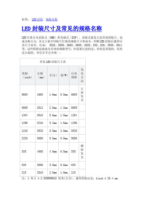
标签:LED封装规格名称
LED封装尺寸及常见的规格名称
LED灯珠分为表贴式(SMD)和直插式(DIP),表贴式就是大家常说的贴片,也成为贴片式,本文主要介绍贴片灯珠的规格尺寸和命名。
单颗LED封装后通常以其尺寸命名,比如: 3528、5050、0603、0805、3020、335、020、3535、3014等,这些简称也就成为具体的规格型号,但需要注意的是:有的是英制的,有的是公制的,单位并不完全统一。
1inch = 25.4 mm
结合上表做一些简单的说明,举例说明LED贴片常见的规格型号及其含义:0603、0805、3528,5050是指表贴型 SMD LED的尺寸大小,也就是对应的规格。
例如:0603指的是长度为0.06英寸,宽度为0.03英寸。
对应公制是1608,即表示LED元件的长度是1.6mm,宽度是0.8mm。
公制叫法1608,英制叫法是0603。
0805对应公制是2012,即表示LED元件的长度是2.0mm,宽度是1.2mm。
公制叫法2012,英制叫法是0805。
但是要注意3528和5050单位是公制。
1210:换算为公制是3528,即表示LED元件的长度是3.5mm,宽度是2.8mm。
行业简称3528,英制叫法是1210。
3528:这是公制叫法,即表封装后LED元件的长度是3.5mm,宽度是2.8mm。
行业简称3528。
5050:这是公制叫法,即表封装后LED元件的长度是5.0mm,宽度是5.0mm。
行业简称5050。
LED各参数随环境温度的变化曲线
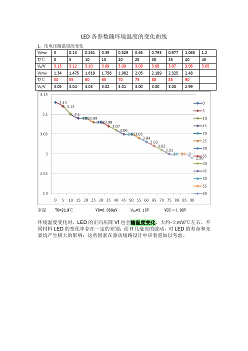
LED各参数随环境温度的变化曲线
室温T0=21.9℃ V0=0.039mV V F0=3.13V VCC=4.98V
环境温度变化时,LED的正向压降Vf也会随温度变化,大约-2mV/℃左右,不同材料LED的变化率存在一定的差别;而If几毫安的波动,对LED的寿命和光衰均产生极大的影响;这些因素在驱动线路设计中应着重加以考虑。
室温T0=23.6℃ V0=0.039mV V R0=3.13V VCC=4.98V 注意:表内的温度都是以室温作为参考点的。
Tuesday, March 18, 2008
室温T0=19.4℃ Ug=0.233 V
发光二极管的输出功率,也随温度的升高而减小。
但由于它不是阈值器件,所以输出功率不会像激光器那样随温度发生很大的变化,在实际使用中也可以不经进行温度控制。
室温T0=20.1℃ Ug0=0.210 V
室温T0=20 ℃
LED亮度Iv随正向电流If变化曲线,低电流时,亮度Iv与电流If 成正比,高电流时,亮度趋于饱和,随电流If 增加Iv基本不再增加;。
- 1、下载文档前请自行甄别文档内容的完整性,平台不提供额外的编辑、内容补充、找答案等附加服务。
- 2、"仅部分预览"的文档,不可在线预览部分如存在完整性等问题,可反馈申请退款(可完整预览的文档不适用该条件!)。
- 3、如文档侵犯您的权益,请联系客服反馈,我们会尽快为您处理(人工客服工作时间:9:00-18:30)。
Customer:Technical Data SheetPN: JT.CB003ZC-B(S)For: IF= 15mAContents1. Features2. Applications3. Package outline dimension4. Absolute maximum ratings5. Electrical-optical characteristics6. Typical electro-optical characteristics curves7. Tapping specifications8. Package method9. Label description10. BIN range11. Reliability test items and conditions12. Precautions for useCustomer confirm Approved byCheckedbyIssuedby1、Features: ※Appearance1.1 Package: 3.8*1.2*0.6mm (Side view white LED)1.2 Emitted Color: White1.3 Mono-color type1.4 Soldering methods: All SMT assembly methods1.5 Comply RoHS standard2、Applications:2.1 LCD back light2.2 Mobile phones: LCD2.3 General use.3、Package Outline Dimension:Recom mended solding pad design polarityNotes: tolerances Unless Dimension ± 0.1mm , Unit = mmNOTES:1. All dimensions are in millimeters (inches).2. Tolerance is ±0.10mm unless otherwise specified.4、Absolute Maximum Ratings(Ta=25℃)Parameter Symbol Rating Unit Power Dissipation Pd 100 mW Forward Current I F30 mA Peak Forward Current *1 I FP100 mA Reverse V oltage V R 5 VSoldering Temperature Tsol260 (for 10seconds)Hand soldering (300 for 3seconds)℃Operating Temperature Topr -35℃~+85℃- Storage Temperature Tstg -40℃~+100℃- Electrostatic discharge ESD 2000(HBM) V* I FP condition: pulse width ≤0.1msec, duty cycle ≤1/10.5、Electrical-optical characteristics(Ta=25℃)Parameter Symbol Min.Typ.Max.Unit Condition Forward V oltage Vf 2.9 3.4 VLuminous Intensity Iv 850 - mcdViewing Angle 2θ1/2- 110 - degI F=15mAReverse Current IR - - 10 µA VR=5VNote: 1. Tolerance of luminous intensity is ±5%2. Tolerance of forward voltage is ±0.03V6、Typical Electro-Optical Characteristics Curves7、Tapping specifications (Units: mm)Loaded quantity: 1000-3000 pcs/reel8、Pac k age Method:(unit:mm)9、Label descriptio n:Such as:BIN: 12/E/71*12 show lumi nous intensity B I N C OD EE show chromaticity coordinates B I N C OD E7-1*show forward voltage B I N C OD E10. BIN rangeLuminous intensity (tolerance is ±5%@ If=15mA):15mA t e st 20m A t e stBIN CODE Min. (mcd)Max. (mcd)Min. (mcd)Max. (mcd)6 850 900110011707 900 950117012308 950 1000123012909 1000 10501290135010 1050 11001350142011 1100 11501420149012 1150 12001490156013 1200 12501560163014 1250 13001630170015 1300 13501700177016 1350 14001770184017 1400 14501840192018 1450 150019202000Chromaticity coordinates specifications(tolerance is ±0.005@If=15mA): NO. x y x y NO.x y x y 0.2601 0.2505 0.2550 0.24250.2676 0.2468 0.2625 0.2388A1 0.2588 0.2406 0.2639 0.2486 B0.2700 0.2350 0.2751 0.24300.2639 0.2486 0.2588 0.24060.2753 0.2588 0.2676 0.2468 A2 0.2625 0.2388 0.2676 0.2468D0.2751 0.2430 0.2828 0.25500.2678 0.2625 0.2601 0.25050.283 0.2708 0.2753 0.2588 C1 0.2639 0.2486 0.2716 0.2606F0.2828 0.2550 0.2905 0.26700.2716 0.2606 0.2639 0.24860.2881 0.2788 0.283 0.2708 C2 0.2676 0.2468 0.2753 0.2588H0.2905 0.2670 0.2956 0.27500.2758 0.2745 0.2678 0.26250.2945 0.2888 0.2881 0.2788 E1 0.2716 0.2606 0.2792 0.2726J0.2956 0.2750 0.3020 0.28500.2792 0.2726 0.2716 0.26060.3009 0.2988 0.2945 0.2888 E2 0.2753 0.2588 0.283 0.27075L0.3020 0.2850 0.3084 0.29500.2806 0.2825 0.2755 0.27450.3073 0.3088 0.30090 0.2988 G1 0.2792 0.2726 0.2844 0.2806N0.3084 0.2950 0.3148 0.30500.2844 0.2806 0.2792 0.27260.3137 0.3188 0.3073 0.3088 G2 0.283 0.2708 0.2881 0.2788P0.3148 0.3050 0.3212 0.31500.2870 0.2925 0.2806 0.28250.2443 0.2413 0.2379 0.2313I1 0.2844 0.2806 0.2908 0.2906 Q00.2454 0.2275 0.2518 0.23750.2908 0.2906 0.2844 0.28060.2539 0.2563 0.2443 0.2413I2 0.2881 0.2788 0.2945 0.2888Q0.2518 0.2375 0.2614 0.25250.2934 0.3025 0.2870 0.29250.2603 0.2663 0.2539 0.2563K1 0.2908 0.2906 0.2972 0.3006R0.2614 0.2525 0.2678 0.2625 0.2972 0.3006 0.2908 0.29060.2667 0.2763 0.2603 0.2663K2 0.2945 0.2888 0.3009 0.2988S0.2678 0.2625 0.2742 0.27250.2998 0.3125 0.2934 0.30250.2731 0.2863 0.2667 0.2763M1 0.2972 0.3006 0.3036 0.3106T0.2742 0.2725 0.2806 0.2825 0.3036 0.3106 0.2972 0.30060.2795 0.2963 0.2731 0.2863M2 0.3009 0.2988 0.3073 0.3088U0.2806 0.2825 0.287 0.2925 0.3062 0.3225 0.2998 0.3125O10.3036 0.3106 0.31 0.32060.31 0.3206 0.3036 0.3106O20.3073 0.3088 0.3137 0.3188THE C.I.E.1931chromaticity diagram(Tolerance+-0.01)Forward voltage (tolerance is ±0.03V@If=15mA):BIN CODE Min.(v) Max.(v)6-1* 2.9 3.06-2* 3.0 3.17-1* 3.1 3.27-2* 3.2 3.38-1* 3.3 3.411、Reliability test items and conditions:No.Test Item Test Conditions Sample size Ac/Re1 Operation Life Test If=DC20mATemp: Room temperatureTest time=1000hrs20 0/12 High TemperatureHigh HumidityTemp. =+65℃RH=90%Test time=240hrs20 0/13 Thermal Shock -40℃~ +100℃20min 10s 20minTest Time=100 cycles20 0/14 High TemperatureStorageHigh Temp. =+100℃Test time=1000hrs20 0/15 Low TemperatureStorageLow Ta=-40℃Test time=1000hrs20 0/16 Temperature Cycle -40℃~ +100℃60min 20min 60minTest Time=20cycle20 0/17 Reflow Soldering Operation heating:260℃(Max.), within 10seconds.(Max.)20 0/1※Judgment criteria of failure for the reliability·Iv: Below 70% of initial values·Vf: Over 20% of upper limit valueNote:1. Measurement shall be taken within 2 hours2. The tested LED have been returned to normal ambient conditions before testing.12、Precautions for use :12.1 SolderingSMD LED encapsulation gumwater is very flexible, outside force easily demolish radiant surface and plastic, As soldering , Please handle with care!a. With No-clean Flux, according to reflow soldering cure condition when soldering,Reflow soldering should not be done more than two times, simultaneity you mustinsure clean on the radiant surface. Otherwise, foreign objects can affect radiant color.b. Don’t process manual soldering except repair. Recommended to be soldered with 25WAnti-static iron, The temp. of the iron should be lower than 300℃and soldering timeshould ,not be done more than three seconds, at the same time iron can’t touch radiantsurface and plasticc. Don’t twist LED in course of manual soldering and experiment, Other wise, the lightswill not work possibly.12.2 Cleaninga. Don’t be cleaned with ultrasonic. Recommended to be wiped with isopropyl alcohol orpure alcohol, wiping time should not be more than one minute. LED must be placed atroom tempe-rature for fifteen minutes before using. After cleaning, you must insureclean on the radiant surface. Otherwise, foreign objects can affect radiant color.b. LED can not be in contact with isoamyl acetate、trichloroethylene、acetone、sulfid、nitride、acid、alkali、salt. These matter can destroy LED.12.3 Sealinga. Sealing glue can not contain sodium ion、sulfid,because these matter can affectfluorescence powder poisoning.b. When using normal sealing glue, Recommended to be operated life for 168hrs under normaltemperature.020.JT.CB003ZC-B(S)12.4 Storagea. Don’t open the moisture proof bag before ready to use the LEDs.b. The LEDs should be kept at 30℃or less and 60%RH or less before opening the package.The max. storage period before opening the package is 1 year.c. After opening the package, the LEDs should be kept at 30-35%RH or less, and it shouldbe used within 7 days.d. If the LEDs be kept over the conditions of c., baking is required before mounting. Bakingcondition as below: 60±5℃for 12 hrs for bulk goods, 105±5℃for 1 hrs for roll goods.e. The environment have no acid、alkali、corrosive gas、intensively shake and high magneticfield.12.5 Statica. Static and Peak surge voltage can destroy LED, Avoiding Instantaneous voltage when turnon or turn off the lights.b. Please wear Anti-static wrist band、Anti-static glove、Anti-static shoes in the course ofoperation, and the equipment must be grounded.c. After LED is be destroyed, leakage current increase obviously, and it will be forwardvoltage falling or failure lamp in the case of low current.12.6 Testa. Customer must apply the current limiting resistor in the circuit so as to drive the LEDswithin the rated current. Otherwise slight voltage shift maybe will cause big currentchange and burn out will happen.b. Also, caution should be taken not to overload the LEDs with instantaneous high voltage atthe turning ON and OFF of the circuit. Otherwise LED will be destroyed, testing methodsas follows:12.7 ElseRadiant color of LEDs have a little change with the current, recommended that LED is used in series and resistance, when lighting, please don’t see directly radiant surface of LED, otherwise LED will burn eyes.Ver. A1Page 11 of 11。
