TL_52652_ASA+PC
Cisco ASA 5585-X 适应性安全设备硬件安装指南说明书

5-1Cisco ASA 5585-X Adaptive Security Appliance Hardware Installation GuideOL-22567-01A P P E N D I X5Cable PinoutsThis appendix describes the ASA 5585-X Ethernet, management, console, and auxiliary ports, and includes the following sections:•ASA 5585-X Cables, page 5-1•RJ-45 Ethernet Ports, page 5-2•Management 10/100/1000 Ethernet Port, page 5-3•Console and Auxiliary Ports (RJ-45), page 5-3•DB9 Connector, page 5-5ASA 5585-X CablesThe ASA 5585-X uses the following cables:•For the Ethernet ports, you can use either straight-through or cross-over twisted-pair cables since all RJ-45 Ethernet ports support MDI/MDIX.NoteAuto-MDI/MDIX refers to the ability of the PHY associated with a given port to sense and automatically switch (if required) the transmit and receive signaling across a twisted-pair RJ-45 cable, thereby eliminating the need for special (for example, cross-over) cables based on the connecting port.•The management ports are 10/100/1000 Mbps-capable; you can also use either straight-through or cross-over twisted-pair cables since the ports also support MDI/MDIX.•The console and auxiliary ports are serial ports and require the use of a flat rollover cable for terminal server connectivity (and a DB9 connector for connection to a PC).5-2Cisco ASA 5585-X Adaptive Security Appliance Hardware Installation GuideOL-22567-01Appendix 5 Cable PinoutsRJ-45 Ethernet Ports5-3Cisco ASA 5585-X Adaptive Security Appliance Hardware Installation GuideOL-22567-01Appendix 5 Cable PinoutsManagement 10/100/1000 Ethernet Port5-4Cisco ASA 5585-X Adaptive Security Appliance Hardware Installation GuideOL-22567-01Appendix 5 Cable PinoutsConsole and Auxiliary Ports (RJ-45)Appendix5 Cable PinoutsDB9 ConnectorDB9 ConnectorTable5-2 lists the cable pinouts for RJ-45 to DB-9.Table5-2Cable Pinouts for RJ-45 to DB-9Signal Console Port RJ-45 Pin DB-9 Pin SignalRTS187CTSDTR274DSRTxD363RxDGND455GNDGND545GNDRxD632TxDDSR726DTRCTS818RTSCisco ASA 5585-X Adaptive Security Appliance Hardware Installation Guide OL-22567-01Appendix5 Cable Pinouts DB9 ConnectorCisco ASA 5585-X Adaptive Security Appliance Hardware Installation GuideOL-22567-01。
第三方路由器固件支持的路由列表
DD WRT目录DD WRT (1)Supported Devices (3)[edit]3com (3)[edit]Abocom (3)[edit]Accton (4)[edit]Aceex (4)[edit]Actiontec (4)[edit]ADI Engineering (4)[edit]Airlink 101 (5)[edit]Airlive / Ovislink (5)[edit]Alfa Networks (6)[edit]Allnet (6)[edit]Anaptyx Wireless Dynamics (7)[edit]Arada Systems (8)[edit]Askey (8)[edit]Asus (8)[edit]Belkin (11)[edit]Bountiful (13)[edit]Browan (13)[edit]Buffalo (13)[edit]Cisco (16)[edit]Conceptronic (22)[edit]Compex (23)[edit]Conrad Elektronic (27)[edit]Corega (27)[edit]Dell (28)[edit]Devolo (28)[edit]Digitus (29)[edit]D-Link (29)[edit]Doodle Labs (31)[edit]Dynex (31)[edit]Edimax (31)[edit]Encore (32)[edit]EnGenius (32)[edit]Exel Networks (32)[edit]Fluidmesh (32)[edit]FON (33)[edit]Fry's Electronics (33)[edit]Gateway (34)[edit]Gateworks (34)[edit]Intellinet (Reichelt) (36)[edit]Iomega (36)[edit]JJPlus (36)[edit]Lanready (37)[edit]Linksys (38)[edit]Logilink (38)[edit]MagicBox (38)[edit]Meraki (38)[edit]Microsoft (39)[edit]Mikrotik Routerboard (39)[edit]Mitsubishi (39)[edit]Motorola (40)[edit]MSI (40)[edit]MTN Electronics (40)[edit]NewMedia (40)[edit]NetComm (41)[edit]NETCORE (41)[edit]PC-Engines (46)[edit]Planex aka PCi (46)[edit]Ravo (46)[edit]RayTalk (46)[edit]Repotec (47)[edit]RFNet Technologies (47)[edit]Rosewill (47)[edit]Senao / EnGenius (48)[edit]Siemens (50)[edit]Sitecom (51)[edit]Snapgear (52)[edit]SOEKRIS Engineering (52)[edit]SparkLAN (53)[edit]Straight Core (53)[edit]Technaxx (53)[edit]Techniclan (54)[edit]Tonze (54)[edit]Toshiba (54)[edit]Tranzeo (54)[edit]TP-Link (55)[edit]TRENDnet (57)[edit]T&W (58)[edit]Ubiquiti (59)[edit]US Robotics (62)[edit]Valemount (63)[edit]Verizon (64)[edit]Viewsonic (65)[edit]VSCOM (65)[edit]Watchguard (65)[edit]WiliGear (66)[edit]WinStars (66)[edit]Wistron (66)[edit]ZCOM (67)OPEN WRT (67)支援的裝置- 路由器類型 (67)評估板/無品牌主機板 (67)3Com (67)Abicom International (67)Actiontec (67)Accton (68)Alcatel-Sbell (68)ALFA Network (68)Allnet (68)ARC Flex (68)Arcadyan (68)Astoria (68)Asus (69)Atmel (70)Avm (70)Aztech (70)Belkin (70)Buffalo (70)CEEDTec (71)Catch Tec (71)Compex (71)Comtrend (71)D-Link (72)Dragino (73)Edimax (73)Engenius (73)Fon (73)Linksys (75)Meraki (76)Netgear (76)PC Engines (77)Planex (78)Qemu (78)Qi hardware (78)Redwave (78)Sagem (78)Scientific Atlanta (78)Sercom (78)Skyline (79)SimpleTech (79)Siemens (79)Sitecom (79)SMC (79)Sparklan (79)Telsey (79)Tenda (79)Texas Instruments (80)Thomson (80)TP-Link (80)Trendnet (82)T-Com / Telekom (82)Ubiquiti (82)Unbranded (83)Upvel (83)Zcomax (83)ZyXEL (84)支援硬體- 開發板, 電話 (84)At91 SoC (84)Freescale (中譯:飛思卡爾) (84)開發中 (84)Tomato DualWAN (84)Tomato (86)Supported Devices[edit]Abocom[edit]Accton[edit]Aceex[edit]Askey[edit]Conrad Elektronic[edit]Corega[edit]Doodle Labs[edit]Dynex[edit]Encore[edit]Fry's Electronics[edit]Gateway[edit]Intellinet (Reichelt)[edit]Microsoft[edit]Mitsubishi[edit]Motorola[edit]MSI[edit]MTN Electronics[edit]NewMedia[edit]Nokia[edit]OpenMesh[edit]Ravo[edit]Rosewill。
各种拓扑图
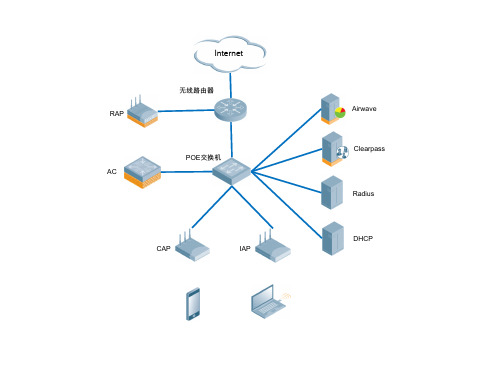
POE交换机 无线AP
POE交换机 无线AP
ClearPass策略管理平台
DHCP 服务器
POE交换机 无线AP
PAD
智能手机
笔记本
PAD
智能手机
笔记本
无线控制器
Internet
流量控制 上网行为管理
办公楼内网
POE交换机 无线AP
汇聚交换机 POE交换机
无线AP
POE交换机 无线AP
PAD
汇聚交换机
…
接入交换机
POE交换机
室外无线AP
室内无线AP
无线网管系统
深澜AAA认证 服务器 DHCP服务器
长安校区AC
雁塔校区AC
主
备
长安校区核心 长安校区核心
大学生活动中心
POE 无线汇聚 楼宇汇聚 AP
行政楼
POE 无线汇聚 楼宇汇聚 AP
逸夫科技信息楼
POE 无线汇聚 楼宇汇聚 AP
研究生教育综合楼
POE交换机
…
POE交换机
室外无线AP PAD
室内无线AP
智能手机
笔记本
ClearPass 认证服务器
AirWave 无线网管系统
DHCP服务器
丽人丽妆 有线网拓扑
Internet
阿尔卡特朗讯 核心交换机 OS6860E-U28
阿尔卡特朗讯 接入交换机 OS6250-48
阿尔卡特朗讯 接入交换机 OS6250-24
认证计费系统
Aruba 7010 无线控制器
西工大校园网
Internet
DHCP
电信4G路由器
电信4G路由器
Aruba RAP-109
TL_52652_2013

Group standardTL 52652Issue 2013-07Class. No.:55121Descriptors:PC+ASA, ASA, PC, polymer blend, trim panel, rear-view mirror, cover, frameASA and PC Polymer Blends Material RequirementsTwo Types: A, B Previous issues TL 52652: 2004-11ChangesThe following changes have been made to TL 52652: 2004-11:–Ball drop test as per PV 3905 and weathering as per PV 3930 added –"Human compatibility" section removed –Notes on testing revised ScopeThis Technical Supply Specification (TL) defines the materials requirements for finished parts made of acrylic-styrene-acrylonitrile (ASA) and polycarbonate (PC) polymer blends, e.g., for un‐painted trim panels and covers (interior trim).DescriptionDescription example for the type with dimensional stability under heat up to +100 °C:ASA+PC polymer blend as per TL 52652-B12Always use the latest version of this standard.This electronically generated standard is authentic and valid without signature.The English translation is believed to be accurate. In case of discrepancies, the German version is alone authoritative and controlling.Numerical notation acc. to ISO/IEC Directives, Part 2.Page 1 of 6All rights reserved. No part of this document may be provided to third parties or reproduced without the prior consent of one of the Volkswagen Group’s Standards departments.© Volkswagen AktiengesellschaftVWNORM-2012-05qPage 2TL 52652: 2013-07Requirements General requirementsApproval of first supply and changes as per Volkswagen standard VW 01155.Emission behavior as per VW 50180 (if required in the drawing).Resistance to open-air weathering as per VW 50185.Colorimetric evaluation as per VW 50190 (if required in the drawing).Avoidance of hazardous substances as per VW 91101.5 finished parts are required for complete testing.AppearanceThe surface and interior of the finished parts must be free of flaws and processing defects such as flow lines, voids, cracks, and the like. Sink marks at the base of ribs and stiffenings are permissible only if they do not adversely affect the part's function or appearance. The finished parts must allow for trouble-free installation.ManufactureInjection molding Types–TL 52652-A PC+ASA polymer blend with increased dimensional stability under heat up to +120 °C–TL 52652-BASA+PC polymer blend, standard type, with dimensional stability under heat up to +100 °CMarking as per VDA 260–TL 52652-A >PC+ASA<–TL 52652-B> ASA+PC <ConditioningPrior to testing, the specimens required for the individual tests must be conditioned for at least 48 h in the standard climate as per ISO 554–23/50.Evaluation of measurement resultsThe required numerical values apply to each individual measurement.MaterialSee section 5.1.Both types: Polymer blends of polycarbonate and acrylic-ester-modified styrene-acrylonitrile resin copolymer, UV-stabilized.3 3.13.23.33.4 3.5 3.63.73.8Page 3TL 52652: 2013-07ColorAs per drawing and/or release.PropertiesSee table 1.Table 13.9 4Page 4TL 52652: 2013-07Notes on testing MaterialIdentification testing takes place by means of infrared spectroscopy.Flexural strengthDetermine the flexural stress under a maximum load as per DIN EN ISO 178, but with a specimen length: (50 ± 1) mm; width: (6 ± 0,2) mm; thickness matching the product's thickness (up to a max.of 4 mm); distance between supports: 40 mm; support surface radius: 1,0 mm to 1,2 mm; test speed: (14 ± 1) mm/min. Specimens taken from finished parts with one-sided graining are placed on the test machine support so that the grained side faces the loading edge.Notched impact strengthIf, for reasons concerning equipment and/or specimen size and shape, a test as perDIN EN ISO 179-1/1eA cannot be performed, the following procedure may be substituted:Impact resistance test (broadside impact) as per DIN EN ISO 179-1, but with: specimen length of (50 ± 1) mm, width of (6 ± 0,2) mm, thickness matching the thickness of the finished product (up to a max. of 4 mm); distance between supports: 40 mm; pendulum impact tester 4J.A 0,8 mm-wide U-shaped notch is made on the broad side of the specimens. The notch depth is 1/3 of the specimen thickness. The edges outlining the notch root must h5 5.15.25.3Page 5TL 52652: 2013-07Finished parts with one-sided graining must be notched on the grained side and subsequentlyplaced on the pendulum impact tester’s specimen supports in such a manner that the center of the notch is precisely within the impact plane. It is important to ensure that the notch is on the side facing away from the hammer edge.However, this requires agreement.Elevated-temperature behaviorHeat-aging test as per DIN 53497, method B, to be performed on at least one complete finished part. Aging period (22 + 2) h.Low-temperature behaviorAge at least one complete finished part in air at (-30 °C ± 1 °C) for (22 + 2) h.Ball drop testBall drop test as per PV 3905 on at least one flat component section. Ball drop height(450 ± 10) mm; ball impact point on upper side of dashboard, for instance, or as specified in draw‐ing.High-temperature light exposureIf the number of exposure periods is not defined in the drawing, the following rule applies:– 3 periods of exposure for components in areas with indirect solar radiation– 5 periods of exposure for components in areas with direct solar radiation (e.g., door waist rail).–10 periods of exposure for components in areas subject to maximum solar radiation (e.g., rear shelf).Applicable documentsThe following documents cited in this standard are necessary to its application.Some of the cited documents are translations from the German original. The translations of Ger‐man terms in such documents may differ from those used in this standard, resulting in terminologi‐cal inconsistency.Standards whose titles are given in German may be available only in German. Editions in other languages may be available from the institution issuing the standard.PV 1303Non-Metallic Materials; Exposure Test of Passenger Compartment Com‐ponentsPV 3905Organic Materials; Ball Drop TestPV 3930Non-Metallic Materials; Weathering in Moist, Hot ClimateTL 1010Materials for Vehicle Interiors; Burning Behavior; Material Requirements VW 01155Vehicle Parts; Approval of First Supply and ChangesVW 50180Components in the Passenger Compartment; Emission Behavior VW 50185Vehicle Parts; Resistance to Open-Air Weathering5.45.55.65.76Page 6TL 52652: 2013-07VW 50190Interior Trim Components; Metrological Evaluation of Color and GlossLevel; Visual Evaluation of Chrome SurfacesVW 91101Environmental Standard for Vehicles; Vehicle Parts, Materials, Operat‐ing Fluids; Avoidance of Hazardous SubstancesDIN 53497Testing of Plastics; Hot Storage Test on Mouldings Made of Thermo‐plastic Moulding Materials without External Mechanical StressingDIN EN 20105-A02Textiles - Tests for colour fastness - Part A02: Grey scale for assessingchange in colourDIN EN ISO 1183-1Plastics - Methods for determining the density of non-cellular plastics -Part 1: Immersion method, liquid pyknometer method and titration meth‐odDIN EN ISO 178Plastics - Determination of flexural propertiesDIN EN ISO 179-1Plastics - Determination of Charpy impact properties - Part 1: Non-instru‐mented impact testDIN EN ISO 306Plastics - Thermoplastic materials - Determination of Vicat softeningtemperature (VST)ISO 554Standard atmospheres for conditioning and/or testing; Specifications VDA 260Components of motor vehicles - Marking of material。
艾泰无线网络解决方案(必来登-酒店2)
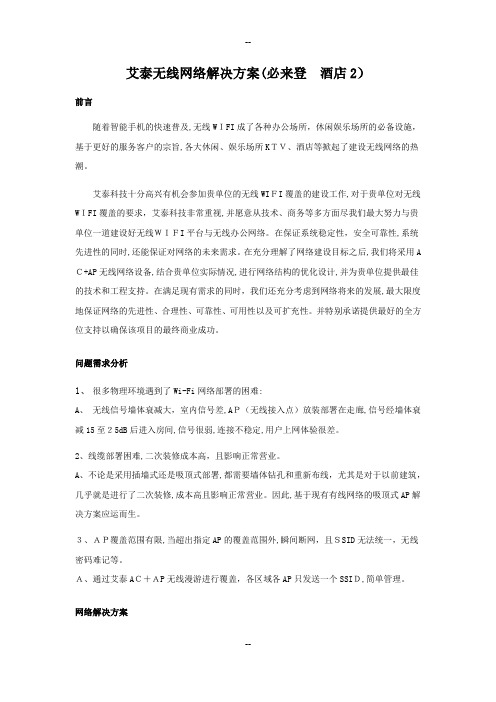
艾泰无线网络解决方案(必来登酒店2)前言随着智能手机的快速普及,无线WIFI成了各种办公场所,休闲娱乐场所的必备设施,基于更好的服务客户的宗旨,各大休闲、娱乐场所KTV、酒店等掀起了建设无线网络的热潮。
艾泰科技十分高兴有机会参加贵单位的无线WIFI覆盖的建设工作,对于贵单位对无线WIFI覆盖的要求,艾泰科技非常重视,并愿意从技术、商务等多方面尽我们最大努力与贵单位一道建设好无线WIFI平台与无线办公网络。
在保证系统稳定性,安全可靠性,系统先进性的同时,还能保证对网络的未来需求。
在充分理解了网络建设目标之后,我们将采用A C+AP无线网络设备,结合贵单位实际情况,进行网络结构的优化设计,并为贵单位提供最佳的技术和工程支持。
在满足现有需求的同时,我们还充分考虑到网络将来的发展,最大限度地保证网络的先进性、合理性、可靠性、可用性以及可扩充性。
并特别承诺提供最好的全方位支持以确保该项目的最终商业成功。
问题需求分析1、很多物理环境遇到了Wi-Fi网络部署的困难:A、无线信号墙体衰减大,室内信号差,AP(无线接入点)放装部署在走廊,信号经墙体衰减15至25dB后进入房间,信号很弱,连接不稳定,用户上网体验很差。
2、线缆部署困难,二次装修成本高,且影响正常营业。
A、不论是采用插墙式还是吸顶式部署,都需要墙体钻孔和重新布线,尤其是对于以前建筑,几乎就是进行了二次装修,成本高且影响正常营业。
因此,基于现有有线网络的吸顶式AP解决方案应运而生。
3、AP覆盖范围有限,当超出指定AP的覆盖范围外,瞬间断网,且SSID无法统一,无线密码难记等。
A、通过艾泰AC+AP无线漫游进行覆盖,各区域各AP只发送一个SSID,简单管理。
网络解决方案在前厅、大堂、等场所,分别部署无线接入点吸顶式AP(WA1900N),实现全网无线覆盖,在客房内安装入墙式(WA300N),实现客房区域内无线覆盖,因考虑到布线美观问题,可直接通过POE供电交换通过网线对吸顶式AP进行供电 ,各场所AP通过旁路由AC进行无线集中管控,实现SSID的统一,无缝漫游需求,无线终端的IP地址获取通过网关路由器(DHC P服务器)进行下发,部署一个SSID,一个网段,如下图所示:拓扑结构描述:在之前原来有线网络不改变基础上,将AC无线控制器配置为“旁路由模式”,单独无线集中控制所有无线AP,AP通过无线控制器进行SSID下发、管制等未完成一系列功能配置操作;AC与AP定义:AC(无线控制器):艾泰科技WX系列无线控制器,支持无线集中管理功能,能管控无线网络中的多个无线接入点(AP),对AP的管理包括:修改相关配置信息、下发配置、软件升级、加入不同服务区等;最多提供10个虚拟服务区域,配合艾泰科技WA系列无线产品(FIT AP)能够为用户提供完善、统一管理的无线网络解决方案。
MOXA全系列产品选型手册

• ISO 9001: 2000 研发 制造及服务 高质量产品设计
• ISO 14001 环境管理系统
• 5年产品质保 绝大多数产品提供5年质保;详细信息请访问Moxa网站
Moxa的绿色产品
欧共体的报废电子电气设备指令( WEEE )自去年8月起开始实施, 对危害物质的限制(RoHS)将从2006 年7月开始强制执行。
• NPort W2250/2150 1/2口设备无线联网服务器
• UC-7420/7410 立即可用的嵌入式智能通讯服务器
9
典型案例
1 环境监控 用于监控无人值守气象站的智能通讯服务器
环境监控
无人值守气象站一般都需要自动运行,基本工作是分析 和预测世界上不断变化的天气状况,它们需要收集和存 储大量的天气数据,并每隔一段时间把它们上传到中心 站的后台计算机进行长期存储。Moxa分布式I/O模块可以 通过RS-485连接到UC-7420,由UC采集气象站传感器的 数据。
* 台积电为台湾半导体制造公司,在全球工业市场 上硅片制造商中排名第一。
Moxa作为全球知名的通讯产品设计和制造商,致力于为最终用户提供可 靠及高性价比的PC-Based、串口转以太网、工业以太网和嵌入式智能通讯 服务器等解决方案。当今世界的趋势,无论是在商业或工业应用领域中, 都已经广泛使用以太网作为通讯的骨干架构。为符合产品在各项领域中的 应用,Moxa已将其研发资源集中在串口转以太网和以太网交换机的技术 提升上。
客户满意度管理
我们定期给所有的Moxa产品终端客户发送“客户满意度调查问卷”,从而 更好的了解客户对Moxa服务和产品的意见,不断改善我们的技术支持策 略,并向您提供更好的服务和产品。
MTSC (Moxa技术支持认证)
NETGEAR FS526Tv2 和 FS728TLP 智能网络交换机安装指南说明书
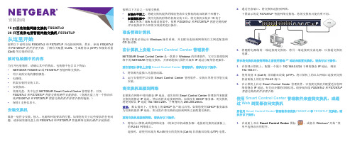
安装指南16口百兆智能网絡交換机 FS526Tv228 口百兆供电型智能网絡交換机 FS728TLP从这里开始按照以下说明安装 FS526Tv2 和 FS728TLP 并连接到网络。
然后,参阅FS526Tv2和 FS728TLP 软件管理手册,了解有关配置 VLAN、生成树协议 (STP) 和服务质量(QoS) 等功能的信息。
核对包装箱中的内容当打开包装箱时,请确认其中的物品。
包装箱中包含以下物品:•NETGEAR FS526Tv2 或 FS728TLP 智能网络交换机。
•用于桌面安装的橡胶脚垫。
•电源线。
•机架安装用安装工具。
•安装指南。
•资源光盘,其中包含 NETGEAR Smart Control Center 管理软件,以及FS526Tv2 和 FS728TLP 智能交换机硬件安装指南。
(资源光盘上有一个指向在线FS526Tv2 和 FS728TLP 智能交换机软件管理手册的链接。
)•保修/支持信息卡。
安装交换机准备一处符合安装、接入、电源和环境要求的位置。
如果您有关于这些要求的任何问题,请参阅资源光盘上的 FS526Tv2 和 FS728TLP 智能网络交换机硬件安装指南。
按照以下方法之一安装交换机•安装在平面上。
将随交换机提供的橡胶垫放在交换机的底部的四个凹槽下。
•安装到机架中。
使用交换机附带的机架安装工具,将交换机安装在 19 英寸(48.3 厘米)EIA 标准设备架中。
按照FS526Tv2 和 FS728TLP 智能交换机硬件安装指南中介绍的安装说明进行操作。
准备管理计算机管理计算机必须运行 Windows 操作系统,并且配有连接到网络的以太网适配器和CD 驱动器。
在计算机上安装 Smart Control Center 管理软件NETGEAR Smart Control Center 是一款基于 Windows 的管理软件,它可以查找您网络中的 NETGEAR 智能交换机,并帮助您执行固件升级和 IP 地址分配等管理操作。
vsphere esx 网卡兼容列表

Supported ReleasesESX / ESXi 4.0*1ESX / ESXi 4.0*2 , ESX 3.5 U4*3 , ESX 3.5 U3*4 , ESX 3.5 U2*3 , ESX 3.5 U1*3 , ESX 3.5*3 , ESXi 3.5 Embedded U4*3 , ESXi 3.5Embedded U3*3 , ESXi 3.5 Embedded U2*3 , ESXi 3.5 Embedded U1*3 , ESXi 3.5 Embedded*3 , ESXi 3.5 Installable U4*3 , ESXi 3.5 Installable U3*3 , ESXi 3.5 Installable U2*3 , ESXi 3.5 Installable U1*3 , ESXi 3.5 Installable*3 , ESX 3.0.3*3 , ESX 3.0.2 U1*3 , ESX 3.0.2*3 , ESX 3.0.1*3ESX / ESXi 4.0*2ESX / ESXi 4.0*1 , ESX 3.5 U4*3 , ESX 3.5 U3*3 , ESX 3.5 U2*3 , ESX 3.5 U1*3 , ESX 3.5*3 , ESXi 3.5 Embedded U4*3 , ESXi 3.5 Embedded U3*3 , ESXi 3.5 Embedded U2*3 , ESXi 3.5 Embedded U1*3 , ESXi 3.5 Embedded*3 , ESXi 3.5 Installable U4*3 , ESXi 3.5 Installable U3*3 , ESXi 3.5 Installable U2*3 , ESXi 3.5 Installable U1*3 , ESXi 3.5 Installable*3 , ESX 3.0.3*3 , ESX 3.0.2 U1*3 , ESX3.0.2*3 , ESX 3.0.1*3ESX / ESXi 4.0*1 , ESX 3.5 U4*3 , ESX 3.5 U3*3 , ESX 3.5 U2*3 , ESX 3.5 U1*3 , ESX 3.5*3 , ESXi 3.5 Embedded U4*3 , ESXi 3.5 Embedded U3*3 , ESXi 3.5 Embedded U2*3 , ESXi 3.5 Embedded U1*3 , ESXi 3.5 Embedded*3 , ESXi 3.5 Installable U4*3 , ESXi 3.5 Installable U3*3 , ESXi 3.5 Installable U2*3 , ESXi 3.5 Installable U1*3 , ESXi 3.5 Installable*3 , ESX 3.0.3*3 , ESX 3.0.2 U1*3 , ESX3.0.2*3 , ESX 3.0.1*3ESX / ESXi 4.0*1 , ESX 3.5 U4*3 , ESX 3.5 U3*3 , ESX 3.5 U2*3 , ESX 3.5 U1*3 , ESX 3.5*3 , ESXi 3.5 Embedded U4*3 , ESXi 3.5 Embedded U3*3 , ESXi 3.5 Embedded U2*3 , ESXi 3.5 Embedded U1*3 , ESXi 3.5 Embedded*3 , ESXi 3.5 Installable U4*3 , ESXi 3.5 Installable U3*3 , ESXi 3.5 Installable U2*3 , ESXi 3.5 Installable U1*3 , ESXi 3.5 Installable*3 , ESX 3.0.3*3 , ESX 3.0.2 U1*3 , ESX3.0.2*3 , ESX 3.0.1*3ESX / ESXi 4.0*2 , ESX 3.5 U4*5 , ESX 3.5 U3*5 , ESX 3.5 U2*5 , ESX 3.5 U1*5 , ESX 3.5*5 , ESXi 3.5 Embedded U4*5 , ESXi 3.5 Embedded U3*5 , ESXi 3.5 Embedded U2*5 , ESXi 3.5 Embedded U1*5 , ESXi 3.5 Embedded*5 , ESXi 3.5 Installable U4*5 , ESXi 3.5 Installable U3*5 , ESXi 3.5 Installable U2*5 , ESXi 3.5 Installable U1*5 , ESXi 3.5 Installable*5 , ESX 3.0.3*6 , ESX 3.0.2 U1*6 , ESX3.0.2*6 , ESX 3.0.1*7 , ESX 3.0*7ESX / ESXi 4.0*2 , ESX 3.0.3*5 , ESX 3.0.2 U1*5 , ESX 3.0.1*7 , ESX 3.0*7ESX / ESXi 4.0*2 , ESX 3.0.3*5 , ESX 3.0.2 U1*5 , ESX 3.0.2*5 , ESX 3.0.1*7 , ESX 3.0*7ESX / ESXi 4.0*2 , ESX 3.5 U4*6 , ESX 3.5 U3*6 , ESX 3.5 U2*6 , ESX 3.5 U1*6 , ESX 3.5*6 , ESXi 3.5 Embedded U4*6 , ESXi 3.5 Embedded U3*6 , ESXi 3.5 Embedded U2*6 , ESXi 3.5 Embedded U1*6 , ESXi 3.5 Embedded*6 , ESXi 3.5 Installable U4*6 , ESXi 3.5 Installable U3*6 , ESXi 3.5 Installable U2*6 , ESXi 3.5 Installable U1*6 , ESXi 3.5 Installable*6 , ESX 3.0.3*5 , ESX 3.0.2 U1*5 , ESX3.0.2*6 , ESX 3.0.1*7 , ESX 3.0*7ESX / ESXi 4.0*1ESX / ESXi 4.0*2ESX / ESXi 4.0*2ESX / ESXi 4.0*1ESX / ESXi 4.0*1ESX / ESXi 4.0*1ESX / ESXi 4.0*1ESX / ESXi 4.0*1ESX / ESXi 4.0*1ESX / ESXi 4.0*1ESX / ESXi 4.0*1ESX / ESXi 4.0*1ESX / ESXi 4.0*1 , ESX 3.5 U4*3 , ESX 3.5 U3*3 , ESX 3.5 U2*3 , ESX 3.5 U1*3 , ESX 3.5*3 , ESXi 3.5 Embedded U4*3 , ESXi 3.5 Embedded U3*3 , ESXi 3.5 Embedded U2*3 , ESXi 3.5 Embedded U1*3 , ESXi 3.5 Embedded*3 , ESXi 3.5 Installable U4*3 , ESXi 3.5 Installable U3*3 , ESXi 3.5 Installable U2*3 , ESXi 3.5 Installable U1*3 , ESXi 3.5 Installable*3 , ESX 3.0.3*3 , ESX 3.0.2 U1*3 , ESX3.0.2*3 , ESX 3.0.1*3ESX / ESXi 4.0*1 , ESX 3.5 U4*3 , ESX 3.5 U3*3 , ESX 3.5 U2*3 , ESX 3.5 U1*3 , ESX 3.5*3 , ESXi 3.5 Embedded U4*3 , ESXi 3.5 Embedded U3*3 , ESXi 3.5 Embedded U2*3 , ESXi 3.5 Embedded U1*3 , ESXi 3.5 Embedded*3 , ESXi 3.5 Installable U4*3 , ESXi 3.5 Installable U3*3 , ESXi 3.5 Installable U2*3 , ESXi 3.5 Installable U1*3 , ESXi 3.5 Installable*3 , ESX 3.0.3*3 , ESX 3.0.2 U1*3 , ESX3.0.2*3 , ESX 3.0.1*3 , ESX 3.0*3ESX / ESXi 4.0*1 , ESX 3.5 U4*3 , ESX 3.5 U3*3 , ESX 3.5 U2*3 , ESX 3.5 U1*3 , ESX 3.5*3 , ESXi 3.5 Embedded U4*3 , ESXi 3.5 Embedded U3*3 , ESXi 3.5 Embedded U2*3 , ESXi 3.5 Embedded U1*3 , ESXi 3.5 Embedded*3 , ESXi 3.5 Installable U4*3 , ESXi 3.5 Installable U3*3 , ESXi 3.5 Installable U2*3 , ESXi 3.5 Installable U1*3 , ESXi 3.5 Installable*3 , ESX 3.0.3*3 , ESX 3.0.2 U1*3 , ESX 3.0.2*3 , ESX 3.0.1*3ESX / ESXi 4.0*1 , ESX 3.5 U4*3 , ESX 3.5 U3*3 , ESX 3.5 U2*3 , ESX 3.5 U1*3 , ESX 3.5*3 , ESXi 3.5 Embedded U4*3 , ESXi 3.5Embedded U3*3 , ESXi 3.5 Embedded U2*3 , ESXi 3.5 Embedded U1*3 , ESXi 3.5 Embedded*3 , ESXi 3.5 Installable U4*3 , ESXi 3.5 Installable U3*3 , ESXi 3.5 Installable U2*3 , ESXi 3.5 Installable U1*3 , ESXi 3.5 Installable*3 , ESX 3.0.3*3 , ESX 3.0.2 U1*3 , ESX 3.0.2*3 , ESX 3.0.1*3ESX / ESXi 4.0*1ESX / ESXi 4.0*1 , ESX 3.5 U4*3 , ESX 3.5 U3*3 , ESX 3.5 U2*3 , ESX 3.5 U1*3 , ESX 3.5*3 , ESXi 3.5 Embedded U4*3 , ESXi 3.5 Embedded U3*3 , ESXi 3.5 Embedded U2*3 , ESXi 3.5 Embedded U1*3 , ESXi 3.5 Embedded*3 , ESXi 3.5 Installable U4*3 , ESXi 3.5 Installable U3*3 , ESXi 3.5 Installable U2*3 , ESXi 3.5 Installable U1*3 , ESXi 3.5 Installable*3 , ESX 3.0.3*3 , ESX 3.0.2 U1*3 , ESX3.0.2*3 , ESX 3.0.1*3ESX / ESXi 4.0*1 , ESX 3.5 U4*3 , ESX 3.5 U3*3 , ESX 3.5 U2*3 , ESX 3.5 U1*3 , ESX 3.5*3 , ESXi 3.5 Embedded U4*3 , ESXi 3.5 Embedded U3*3 , ESXi 3.5 Embedded U2*3 , ESXi 3.5 Embedded U1*3 , ESXi 3.5 Embedded*3 , ESXi 3.5 Installable U4*3 , ESXi 3.5 Installable U3*3 , ESXi 3.5 Installable U2*3 , ESXi 3.5 Installable U1*3 , ESXi 3.5 Installable*3 , ESX 3.0.3*3 , ESX 3.0.2 U1*3 , ESX3.0.2*3 , ESX 3.0.1*3 , ESX 3.0*3ESX / ESXi 4.0*1 , ESX 3.5 U4*3 , ESX 3.5 U3*3 , ESX 3.5 U2*3 , ESX 3.5 U1*3 , ESX 3.5*3 , ESXi 3.5 Embedded U4*3 , ESXi 3.5 Embedded U3*3 , ESXi 3.5 Embedded U2*3 , ESXi 3.5 Embedded U1*3 , ESXi 3.5 Embedded*3 , ESXi 3.5 Installable U4*3 , ESXi 3.5 Installable U3*3 , ESXi 3.5 Installable U2*3 , ESXi 3.5 Installable U1*3 , ESXi 3.5 Installable*3 , ESX 3.0.3*3 , ESX 3.0.2 U1*3 , ESX3.0.2*3 , ESX 3.0.1*3 , ESX 3.0*3ESX / ESXi 4.0*1 , ESX 3.5 U4*3 , ESX 3.5 U3*3 , ESX 3.5 U2*3 , ESX 3.5 U1*3 , ESX 3.5*3 , ESXi 3.5 Embedded U4*3 , ESXi 3.5 Embedded U3*3 , ESXi 3.5 Embedded U2*3 , ESXi 3.5 Embedded U1*3 , ESXi 3.5 Embedded*3 , ESXi 3.5 Installable U4*3 , ESXi 3.5 Installable U3*3 , ESXi 3.5 Installable U2*3 , ESXi 3.5 Installable U1*3 , ESXi 3.5 Installable*3 , ESX 3.0.3*3 , ESX 3.0.2 U1*3 , ESX3.0.2*3 , ESX 3.0.1*3 , ESX 3.0*3ESX / ESXi 4.0*1 , ESX 3.5 U4*3 , ESX 3.5 U3*3 , ESX 3.5 U2*3 , ESX 3.5 U1*3 , ESX 3.5*3 , ESXi 3.5 Embedded U4*3 , ESXi 3.5 Embedded U3*3 , ESXi 3.5 Embedded U2*3 , ESXi 3.5 Embedded U1*3 , ESXi 3.5 Embedded*3 , ESXi 3.5 Installable U4*3 , ESXi 3.5 Installable U3*3 , ESXi 3.5 Installable U2*3 , ESXi 3.5 Installable U1*3 , ESXi 3.5 Installable*3 , ESX 3.0.3*3 , ESX 3.0.2 U1*3 , ESX3.0.2*3 , ESX 3.0.1*3 , ESX 3.0*3ESX / ESXi 4.0*1 , ESX 3.5 U4*3 , ESX 3.5 U3*3 , ESX 3.5 U2*3 , ESX 3.5 U1*3 , ESX 3.5*3 , ESXi 3.5 Embedded U4*3 , ESXi 3.5 Embedded U3*3 , ESXi 3.5 Embedded U2*3 , ESXi 3.5 Embedded U1*3 , ESXi 3.5 Embedded*3 , ESXi 3.5 Installable U4*3 , ESXi 3.5 Installable U3*3 , ESXi 3.5 Installable U2*3 , ESXi 3.5 Installable U1*3 , ESXi 3.5 Installable*3 , ESX 3.0.3*3 , ESX 3.0.2 U1*3 , ESX3.0.2*3 , ESX 3.0.1*3 , ESX 3.0*3ESX / ESXi 4.0*1 , ESX 3.5 U4*3 , ESX 3.5 U3*3 , ESX 3.5 U2*3 , ESX 3.5 U1*3 , ESX 3.5*3 , ESXi 3.5 Embedded U4*3 , ESXi 3.5 Embedded U3*3 , ESXi 3.5 Embedded U2*3 , ESXi 3.5 Embedded U1*3 , ESXi 3.5 Embedded*3 , ESXi 3.5 Installable U4*3 , ESXi 3.5 Installable U3*3 , ESXi 3.5 Installable U2*3 , ESXi 3.5 Installable U1*3 , ESXi 3.5 Installable*3 , ESX 3.0.3*3 , ESX 3.0.2 U1*3 , ESX3.0.2*3 , ESX 3.0.1*3 , ESX 3.0*3ESX / ESXi 4.0*1 , ESX 3.5 U4*3 , ESX 3.5 U3*3 , ESX 3.5 U2*3 , ESX 3.5 U1*3 , ESX 3.5*3 , ESXi 3.5 Embedded U4*3 , ESXi 3.5 Embedded U3*3 , ESXi 3.5 Embedded U2*3 , ESXi 3.5 Embedded U1*3 , ESXi 3.5 Embedded*3 , ESXi 3.5 Installable U4*3 , ESXi 3.5 Installable U3*3 , ESXi 3.5 Installable U2*3 , ESXi 3.5 Installable U1*3 , ESXi 3.5 Installable*3 , ESX 3.0.3*3 , ESX 3.0.2 U1*3 , ESX3.0.2*3 , ESX 3.0.1*3 , ESX 3.0*3ESX / ESXi 4.0*1 , ESX 3.5 U4*3 , ESX 3.5 U3*3 , ESX 3.5 U2*3 , ESX 3.5 U1*3 , ESX 3.5*3 , ESXi 3.5 Embedded U4*3 , ESXi 3.5 Embedded U3*3 , ESXi 3.5 Embedded U2*3 , ESXi 3.5 Embedded U1*3 , ESXi 3.5 Embedded*3 , ESXi 3.5 Installable U4*3 , ESXi 3.5 Installable U3*3 , ESXi 3.5 Installable U2*3 , ESXi 3.5 Installable U1*3 , ESXi 3.5 Installable*3 , ESX 3.0.3*3 , ESX 3.0.2 U1*3 , ESX3.0.2*3 , ESX 3.0.1*3 , ESX 3.0*3ESX / ESXi 4.0*1 , ESX 3.5 U4*3 , ESX 3.5 U3*3 , ESX 3.5 U2*3 , ESX 3.5 U1*3 , ESX 3.5*3 , ESXi 3.5 Embedded U4*3 , ESXi 3.5 Embedded U3*3 , ESXi 3.5 Embedded U2*3 , ESXi 3.5 Embedded U1*3 , ESXi 3.5 Embedded*3 , ESXi 3.5 Installable U4*3 , ESXi 3.5 Installable U3*3 , ESXi 3.5 Installable U2*3 , ESXi 3.5 Installable U1*3 , ESXi 3.5 Installable*3 , ESX 3.0.3*3 , ESX 3.0.2 U1*3 , ESX3.0.2*3 , ESX 3.0.1*3 , ESX 3.0*3ESX / ESXi 4.0*1 , ESX 3.5 U4*3 , ESX 3.5 U3*3 , ESX 3.5 U2*3 , ESX 3.5 U1*3 , ESX 3.5*3 , ESXi 3.5 Embedded U4*3 , ESXi 3.5 Embedded U3*3 , ESXi 3.5 Embedded U2*3 , ESXi 3.5 Embedded U1*3 , ESXi 3.5 Embedded*3 , ESXi 3.5 Installable U4*3 , ESXi 3.5 Installable U3*3 , ESXi 3.5 Installable U2*3 , ESXi 3.5 Installable U1*3 , ESXi 3.5 Installable*3 , ESX 3.0.3*3 , ESX 3.0.2 U1*3 , ESX3.0.2*3 , ESX 3.0.1*3 , ESX 3.0*3ESX / ESXi 4.0*1 , ESX 3.5 U4*3 , ESX 3.5 U3*3 , ESX 3.5 U2*3 , ESX 3.5 U1*3 , ESX 3.5*3 , ESXi 3.5 Embedded U4*3 , ESXi 3.5 Embedded U3*3 , ESXi 3.5 Embedded U2*3 , ESXi 3.5 Embedded U1*3 , ESXi 3.5 Embedded*3 , ESXi 3.5 Installable U4*3 , ESXi 3.5 Installable U3*3 , ESXi 3.5 Installable U2*3 , ESXi 3.5 Installable U1*3 , ESXi 3.5 Installable*3 , ESX 3.0.3*3 , ESX 3.0.2 U1*3 , ESX3.0.2*3 , ESX 3.0.1*3 , ESX 3.0*3ESX / ESXi 4.0*1ESX / ESXi 4.0*1 , ESX 3.0.3*8 , ESX 3.0.2 U1*8 , ESX 3.0.2*8 , ESX 3.0.1*3 , ESX 3.0*3ESX / ESXi 4.0*1ESX / ESXi 4.0*1 , ESX 3.5 U4*3 , ESX 3.5 U3*3 , ESX 3.5 U2*3 , ESX 3.5 U1*3 , ESX 3.5*3 , ESXi 3.5 Embedded U4*3 , ESXi 3.5 Embedded U3*3 , ESXi 3.5 Embedded U2*3 , ESXi 3.5 Embedded U1*3 , ESXi 3.5 Embedded*3 , ESXi 3.5 Installable U4*3 , ESXi 3.5 Installable U3*3 , ESXi 3.5 Installable U2*3 , ESXi 3.5 Installable U1*3 , ESXi 3.5 Installable*3 , ESX 3.0.3*3 , ESX 3.0.2 U1*3 , ESX3.0.2*3 , ESX 3.0.1*3 , ESX 3.0*3ESX / ESXi 4.0*1 , ESX 3.5 U4*9 , ESXi 3.5 Embedded U4*9 , ESXi 3.5 Installable U4*9ESX / ESXi 4.0*1ESX / ESXi 4.0*1ESX / ESXi 4.0*1ESX / ESXi 4.0*1ESX / ESXi 4.0*1ESX / ESXi 4.0*1ESX / ESXi 4.0*1ESX / ESXi 4.0*1ESX / ESXi 4.0*1ESX / ESXi 4.0*1ESX / ESXi 4.0*1ESX / ESXi 4.0*1ESX / ESXi 4.0*1ESX / ESXi 4.0*1 , ESX 3.5 U4*9 , ESX 3.5 U3*9 , ESX 3.5 U2*9 , ESXi 3.5 Embedded U4*9 , ESXi 3.5 Embedded U3*9 , ESXi 3.5Embedded U2*9 , ESXi 3.5 Installable U4*9 , ESXi 3.5 Installable U3*9 , ESXi 3.5 Installable U2*9ESX / ESXi 4.0*1 , ESX 3.5 U4*9 , ESX 3.5 U3*9 , ESX 3.5 U2*9 , ESXi 3.5 Embedded U4*9 , ESXi 3.5 Embedded U3*9 , ESXi 3.5 Embedded U2*9 , ESXi 3.5 Installable U4*9 , ESXi 3.5 Installable U3*9 , ESXi 3.5 Installable U2*9ESX / ESXi 4.0*1 , ESX 3.5 U4*9 , ESX 3.5 U3*9 , ESX 3.5 U2*9 , ESXi 3.5 Embedded U4*9 , ESXi 3.5 Embedded U3*9 , ESXi 3.5 Embedded U2*9 , ESXi 3.5 Installable U4*9 , ESXi 3.5 Installable U3*9 , ESXi 3.5 Installable U2*9ESX / ESXi 4.0*1ESX / ESXi 4.0*1 , ESX 3.5 U4*3 , ESX 3.5 U3*3 , ESX 3.5 U2*3 , ESX 3.5 U1*3 , ESX 3.5*3 , ESXi 3.5 Embedded U4*3 , ESXi 3.5 Embedded U3*3 , ESXi 3.5 Embedded U2*3 , ESXi 3.5 Embedded U1*3 , ESXi 3.5 Embedded*3 , ESXi 3.5 Installable U4*3 , ESXi 3.5 Installable U3*3 , ESXi 3.5 Installable U2*3 , ESXi 3.5 Installable U1*3 , ESXi 3.5 Installable*3 , ESX 3.0.3*3 , ESX 3.0.2 U1*3 , ESX 3.0.2*3 , ESX 3.0.1*3ESX / ESXi 4.0*1ESX / ESXi 4.0*1 , ESX 3.5 U4*3 , ESX 3.5 U3*3 , ESX 3.5 U2*3 , ESX 3.5 U1*3 , ESX 3.5*3 , ESXi 3.5 Embedded U4*3 , ESXi 3.5 Embedded U3*3 , ESXi 3.5 Embedded U2*3 , ESXi 3.5 Embedded U1*3 , ESXi 3.5 Embedded*3 , ESXi 3.5 Installable U4*3 , ESXi 3.5 Installable U3*3 , ESXi 3.5 Installable U2*3 , ESXi 3.5 Installable U1*3 , ESXi 3.5 Installable*3 , ESX 3.0.3*3 , ESX 3.0.2 U1*3 , ESX3.0.2*3 , ESX 3.0.1*3 , ESX 3.0*3ESX / ESXi 4.0*1 , ESX 3.5 U4*3 , ESX 3.5 U3*3 , ESX 3.5 U2*3 , ESX 3.5 U1*3 , ESX 3.5*3 , ESXi 3.5 Embedded U4*3 , ESXi 3.5 Embedded U3*3 , ESXi 3.5 Embedded U2*3 , ESXi 3.5 Embedded U1*3 , ESXi 3.5 Embedded*3 , ESXi 3.5 Installable U4*3 , ESXi 3.5 Installable U3*3 , ESXi 3.5 Installable U2*3 , ESXi 3.5 Installable U1*3 , ESXi 3.5 Installable*3 , ESX 3.0.3*3 , ESX 3.0.2 U1*3 , ESX3.0.2*3 , ESX 3.0.1*3 , ESX 3.0*3ESX / ESXi 4.0*1 , ESX 3.5 U4*3 , ESX 3.5 U3*3 , ESX 3.5 U2*3 , ESX 3.5 U1*3 , ESX 3.5*3 , ESXi 3.5 Embedded U4*3 , ESXi 3.5 Embedded U3*3 , ESXi 3.5 Embedded U2*3 , ESXi 3.5 Embedded U1*3 , ESXi 3.5 Embedded*3 , ESXi 3.5 Installable U4*3 , ESXi 3.5 Installable U3*3 , ESXi 3.5 Installable U2*3 , ESXi 3.5 Installable U1*3 , ESXi 3.5 Installable*3 , ESX 3.0.3*3 , ESX 3.0.2 U1*3 , ESX3.0.2*3 , ESX 3.0.1*3 , ESX 3.0*3ESX / ESXi 4.0*1 , ESX 3.5 U4*3 , ESX 3.5 U3*3 , ESX 3.5 U2*3 , ESX 3.5 U1*3 , ESX 3.5*3 , ESXi 3.5 Embedded U4*3 , ESXi 3.5 Embedded U3*3 , ESXi 3.5 Embedded U2*3 , ESXi 3.5 Embedded U1*3 , ESXi 3.5 Embedded*3 , ESXi 3.5 Installable U4*3 , ESXi 3.5 Installable U3*3 , ESXi 3.5 Installable U2*3 , ESXi 3.5 Installable U1*3 , ESXi 3.5 Installable*3 , ESX 3.0.3*3 , ESX 3.0.2 U1*3 , ESX3.0.2*3 , ESX 3.0.1*3 , ESX 3.0*3ESX / ESXi 4.0*1ESX / ESXi 4.0*1ESX / ESXi 4.0*2 , ESX 3.0.3*5 , ESX 3.0.2 U1*5 , ESX 3.0.1*7 , ESX 3.0*7ESX / ESXi 4.0*101 , ESX 3.5 U4*11 , ESX 3.5 U3*11 , ESXi 3.5 Embedded U4*11 , ESXi 3.5 Embedded U3*11 , ESXi 3.5 Installable U4*11 , ESXi 3.5 Installable U3*11ESX / ESXi 4.0*10 , ESX 3.5 U4*11 , ESX 3.5 U3*11 , ESXi 3.5 Embedded U4*11 , ESXi 3.5 Embedded U3*11 , ESXi 3.5 Installable U4*11 , ESXi 3.5 Installable U3*11ESX / ESXi 4.0*2ESX / ESXi 4.0*12 , ESX 3.5 U4*13 , ESXi 3.5 Embedded U4*13 , ESXi 3.5 Installable U4*13ESX / ESXi 4.0*1ESX / ESXi 4.0*1 , ESX 3.5 U4*3 , ESX 3.5 U3*3 , ESX 3.5 U2*3 , ESX 3.5 U1*3 , ESX 3.5*3 , ESXi 3.5 Embedded U4*3 , ESXi 3.5 Embedded U3*3 , ESXi 3.5 Embedded U2*3 , ESXi 3.5 Embedded U1*3 , ESXi 3.5 Embedded*3 , ESXi 3.5 Installable U1*3 , ESXi 3.5 Installable*3 , ESX 3.0.3*8 , ESX 3.0.2 U1*8 , ESX 3.0.2*8 , ESX 3.0.1*8 , ESX 3.0*3ESX / ESXi 4.0*2 , ESX 3.5 U2*5 , ESX 3.5 U1*5 , ESX 3.5*5 , ESXi 3.5 Embedded U4*5 , ESXi 3.5 Embedded U3*5 , ESXi 3.5 Embedded U2*5 , ESXi 3.5 Embedded U1*5 , ESXi 3.5 Embedded*5 , ESXi 3.5 Installable U4*5 , ESXi 3.5 Installable U3*5 , ESXi 3.5 Installable U2*5 , ESXi 3.5 Installable U1*5 , ESXi 3.5 Installable*5 , ESX 3.0.3*5 , ESX 3.0.2 U1*5 , ESX 3.0.2*5 , ESX 3.0.1*7 , ESX 3.0*7ESX / ESXi 4.0*2 , ESX 3.5 U4*5 , ESX 3.5 U3*5 , ESX 3.5 U2*5 , ESX 3.5 U1*5 , ESX 3.5*5 , ESXi 3.5 Embedded U4*5 , ESXi 3.5 Embedded U3*5 , ESXi 3.5 Embedded U2*5 , ESXi 3.5 Embedded U1*5 , ESXi 3.5 Embedded*5 , ESXi 3.5 Installable U1*5 , ESXi 3.5 Installable*5 , ESX 3.0.3*5 , ESX 3.0.2 U1*5 , ESX 3.0.2*5 , ESX 3.0.1*7 , ESX 3.0*7ESX / ESXi 4.0*2 , ESX 3.5 U4*5 , ESX 3.5 U3*5 , ESX 3.5 U2*5 , ESX 3.5 U1*5 , ESX 3.5*5 , ESXi 3.5 Embedded U4*5 , ESXi 3.5 Embedded U3*5 , ESXi 3.5 Embedded U2*5 , ESXi 3.5 Embedded U1*5 , ESXi 3.5 Embedded*5 , ESXi 3.5 Installable U1*5 , ESXi 3.5 Installable*5 , ESX 3.0.3*5 , ESX 3.0.2 U1*5 , ESX 3.0.2*5 , ESX 3.0.1*7 , ESX 3.0*7ESX / ESXi 4.0*2 , ESX 3.5 U4*5 , ESX 3.5 U3*5 , ESX 3.5 U2*5 , ESX 3.5 U1*5 , ESX 3.5*5 , ESXi 3.5 Embedded U4*5 , ESXi 3.5 Embedded U3*5 , ESXi 3.5 Embedded U2*5 , ESXi 3.5 Embedded U1*5 , ESXi 3.5 Embedded*5 , ESXi 3.5 Installable U1*5 , ESXi 3.5 Installable*5 , ESX 3.0.3*5 , ESX 3.0.2 U1*5 , ESX 3.0.2*5 , ESX 3.0.1*7 , ESX 3.0*7ESX / ESXi 4.0*2 , ESX 3.5 U4*5 , ESX 3.5 U3*5 , ESX 3.5 U2*5 , ESX 3.5 U1*5 , ESX 3.5*5 , ESXi 3.5 Embedded U4*5 , ESXi 3.5 Embedded U3*5 , ESXi 3.5 Embedded U2*5 , ESXi 3.5 Embedded U1*5 , ESXi 3.5 Embedded*5 , ESXi 3.5 Installable U1*5 , ESXi 3.5 Installable*5 , ESX 3.0.3*5 , ESX 3.0.2 U1*5 , ESX 3.0.2*5 , ESX 3.0.1*7 , ESX 3.0*7ESX / ESXi 4.0*2 , ESX 3.5 U4*5 , ESX 3.5 U3*5 , ESX 3.5 U2*5 , ESX 3.5 U1*5 , ESX 3.5*5 , ESXi 3.5 Embedded U4*5 , ESXi 3.5 Embedded U3*5 , ESXi 3.5 Embedded U2*5 , ESXi 3.5 Embedded U1*5 , ESXi 3.5 Embedded*5 , ESXi 3.5 Installable U1*5 , ESXi 3.5 Installable*5 , ESX 3.0.3*5 , ESX 3.0.2 U1*5 , ESX 3.0.2*5 , ESX 3.0.1*7 , ESX 3.0*7ESX / ESXi 4.0*2 , ESX 3.5 U4*5 , ESX 3.5 U3*5 , ESX 3.5 U2*5 , ESX 3.5 U1*5 , ESX 3.5*5 , ESXi 3.5 Embedded U4*5 , ESXi 3.5 Embedded U3*5 , ESXi 3.5 Embedded U2*5 , ESXi 3.5 Embedded U1*5 , ESXi 3.5 Embedded*5 , ESXi 3.5 Installable U4*5 , ESXi 3.5 Installable U3*5 , ESXi 3.5 Installable U2*5 , ESXi 3.5 Installable U1*5 , ESXi 3.5 Installable*5 , ESX 3.0.3*5 , ESX 3.0.2 U1*5 , ESX3.0.2*5 , ESX 3.0.1*7ESX / ESXi 4.0*2ESX / ESXi 4.0*2 , ESX 3.5 U4*5 , ESX 3.5 U3*5 , ESX 3.5 U2*5 , ESX 3.5 U1*5 , ESX 3.5*5 , ESXi 3.5 Embedded U4*5 , ESXi 3.5 Embedded U3*5 , ESXi 3.5 Embedded U2*5 , ESXi 3.5 Embedded U1*5 , ESXi 3.5 Embedded*5 , ESXi 3.5 Installable U4*5 , ESXi 3.5 Installable U3*5 , ESXi 3.5 Installable U2*5 , ESXi 3.5 Installable U1*5 , ESXi 3.5 Installable*5 , ESX 3.0.3*5 , ESX 3.0.2 U1*5 , ESX3.0.2*5 , ESX 3.0.1*7ESX / ESXi 4.0*2ESX / ESXi 4.0*2 , ESX 3.5 U4*5 , ESX 3.5 U3*5 , ESX 3.5 U2*5 , ESX 3.5 U1*5 , ESX 3.5*5 , ESXi 3.5 Embedded U1*5 , ESXi 3.5 Embedded*5 , ESXi 3.5 Installable U1*5 , ESXi 3.5 Installable*5 , ESX 3.0.3*5 , ESX 3.0.2 U1*5 , ESX 3.0.2*5 , ESX 3.0.1*7 , ESX 3.0*7 ESX / ESXi 4.0*2 , ESX 3.5*5 , ESXi 3.5 Embedded U4*5 , ESXi 3.5 Embedded U3*5 , ESXi 3.5 Embedded U2*5 , ESXi 3.5 Embedded U1*5 , ESXi 3.5 Embedded*5 , ESXi 3.5 Installable U1*5 , ESXi 3.5 Installable*5 , ESX 3.0.3*5 , ESX 3.0.2 U1*5 , ESX 3.0.2*5 , ESX 3.0.1*7 , ESX 3.0*7ESX / ESXi 4.0*1 , ESX 3.5 U4*5 , ESX 3.5 U3*5 , ESX 3.5 U2*5 , ESX 3.5 U1*5 , ESX 3.5*5 , ESXi 3.5 Embedded U4*5 , ESXi 3.5 Embedded U3*5 , ESXi 3.5 Embedded U2*5 , ESXi 3.5 Embedded U1*5 , ESXi 3.5 Embedded*5 , ESXi 3.5 Installable U1*5 , ESXi 3.5 Installable*5 , ESX 3.0.3*5 , ESX 3.0.2 U1*5 , ESX 3.0.2*5 , ESX 3.0.1*7 , ESX 3.0*7ESX / ESXi 4.0*2ESX / ESXi 4.0*2ESX / ESXi 4.0*2ESX / ESXi 4.0*2ESX / ESXi 4.0*12 , ESX 3.5 U4*142,3,4kb: 1,2 , ESX 3.5 U3*132,3,4kb: 1,2ESX / ESXi 4.0*12 , ESX 3.5 U4*14 , ESX 3.5 U3*14ESX / ESXi 4.0*12 , ESX 3.5 U4*14 , ESX 3.5 U3*12ESX / ESXi 4.0*161 , ESX 3.5 U4*172,4kb: 3 , ESX 3.5 U3*172,4kb: 3ESX / ESXi 4.0*185ESX / ESXi 4.0*165ESX / ESXi 4.0*19 , ESX 3.5 U4*206 , ESX 3.5 U3*206 , ESX 3.5 U2*206 , ESX 3.5 U1*206 , ESX 3.5*206 , ESXi 3.5 EmbeddedU4*206 , ESXi 3.5 Embedded U3*206 , ESXi 3.5 Embedded U2*206 , ESXi 3.5 Embedded U1*206 , ESXi 3.5 Embedded*206 , ESXi 3.5 Installable U4*206 , ESXi 3.5 Installable U3*206 , ESXi 3.5 Installable U2*206 , ESXi 3.5 Installable U1*206 , ESXi 3.5 Installable*206 , ESX 3.0.3*206 , ESX 3.0.2 U1*207,6 , ESX 3.0.2*206ESX / ESXi 4.0*21 , ESX 3.5 U4*22 , ESX 3.5 U2*22 , ESX 3.5 U1*22 , ESX 3.5*22 , ESXi 3.5 Embedded U2*22 , ESXi 3.5 Embedded U1*22 , ESXi 3.5 Embedded*22 , ESXi 3.5 Installable U4*22 , ESXi 3.5 Installable U3*22 , ESXi 3.5 Installable U2*22 , ESXi 3.5 Installable U1*22 , ESXi 3.5 Installable*22ESX / ESXi 4.0*21 , ESX 3.5 U4*22 , ESX 3.5 U3*22 , ESX 3.5 U2*22 , ESX 3.5 U1*22 , ESX 3.5*22 , ESXi 3.5 Embedded U4*22 , ESXi 3.5 Embedded U3*22 , ESXi 3.5 Embedded U2*22 , ESXi 3.5 Embedded U1*22 , ESXi 3.5 Embedded*22 , ESXi 3.5 InstallableU4*22 , ESXi 3.5 Installable U3*22 , ESXi 3.5 Installable U2*22 , ESXi 3.5 Installable U1*22 , ESXi 3.5 Installable*22 , ESX 3.0.3*22 , ESX 3.0.2 U1*22 , ESX 3.0.2*22 , ESX 3.0.1*238ESX / ESXi 4.0*21 , ESX 3.5 U4*22 , ESX 3.5 U3*22 , ESX 3.5 U2*22 , ESX 3.5 U1*22 , ESX 3.5*22 , ESXi 3.5 Embedded U4*22 , ESXi 3.5 Embedded U3*22 , ESXi 3.5 Embedded U2*22 , ESXi 3.5 Embedded U1*22 , ESXi 3.5 Embedded*22 , ESXi 3.5 InstallableU4*22 , ESXi 3.5 Installable U3*22 , ESXi 3.5 Installable U2*22 , ESXi 3.5 Installable U1*22 , ESXi 3.5 Installable*22 , ESX 3.0.3*22 , ESX 3.0.2 U1*22 , ESX 3.0.2*22 , ESX 3.0.1*22 , ESX 3.0*24ESX / ESXi 4.0*2 , ESX 3.5 U4*7 , ESX 3.5 U3*7 , ESX 3.5 U2*7 , ESX 3.5 U1*7 , ESX 3.5*7 , ESXi 3.5 Embedded U4*7 , ESXi 3.5 Embedded U3*7 , ESXi 3.5 Embedded U2*7 , ESXi 3.5 Embedded U1*7 , ESXi 3.5 Embedded*7 , ESXi 3.5 Installable U4*7 , ESXi 3.5 Installable U3*7 , ESXi 3.5 Installable U2*7 , ESXi 3.5 Installable U1*7 , ESXi 3.5 Installable*7 , ESX 3.0.3*3 , ESX 3.0.2 U1*3 , ESX3.0.2*3 , ESX 3.0.1*3 , ESX 3.0*7ESX / ESXi 4.0*1 , ESX 3.5 U4*3 , ESX 3.5 U3*3 , ESX 3.5 U2*3 , ESX 3.5 U1*3 , ESX 3.5*3 , ESXi 3.5 Installable U4*3 , ESXi 3.5 Installable U3*3 , ESXi 3.5 Installable U2*3 , ESXi 3.5 Installable U1*3 , ESXi 3.5 Installable*3 , ESX 3.0.1*3 , ESX 3.0*3ESX / ESXi 4.0*19 , ESX 3.5 U4*20 , ESX 3.5 U3*20 , ESX 3.5 U2*20 , ESX 3.5 U1*20 , ESX 3.5*20 , ESXi 3.5 Embedded U4*20 , ESXi 3.5 Embedded U3*20 , ESXi 3.5 Embedded U2*20 , ESXi 3.5 Embedded U1*20 , ESXi 3.5 Embedded*20 , ESXi 3.5 InstallableU4*20 , ESXi 3.5 Installable U3*20 , ESXi 3.5 Installable U2*20 , ESXi 3.5 Installable U1*20 , ESXi 3.5 Installable*20 , ESX 3.0.3*20 ,ESX 3.0.2 U1*20ESX / ESXi 4.0*1 , ESX 3.5 U4*3 , ESX 3.5 U3*3 , ESX 3.5 U2*3 , ESX 3.5 U1*3 , ESX 3.5*3 , ESX 3.0.3*3 , ESX 3.0.2 U1*3 , ESX 3.0.2*3 , ESX 3.0.1*3ESX / ESXi 4.0*2ESX / ESXi 4.0*1ESX / ESXi 4.0*1ESX / ESXi 4.0*21 , ESX 3.5 U4*22 , ESX 3.5 U3*22 , ESX 3.5 U2*22 , ESX 3.5 U1*22 , ESX 3.5*22 , ESXi 3.5 Embedded U4*22 , ESXi 3.5 Embedded U3*22 , ESXi 3.5 Embedded U2*22 , ESXi 3.5 Embedded U1*22 , ESXi 3.5 Embedded*22 , ESXi 3.5 InstallableU4*22 , ESXi 3.5 Installable U3*22 , ESXi 3.5 Installable U2*22 , ESXi 3.5 Installable U1*22 , ESXi 3.5 Installable*22 , ESX 3.0.3*22 , ESX 3.0.2 U1*22 , ESX 3.0.2*22 , ESX 3.0.1*22 , ESX 3.0*24ESX / ESXi 4.0*21ESX / ESXi 4.0ESX / ESXi 4.0*1 , ESX 3.5 U4*9 , ESX 3.5 U3*9 , ESX 3.5 U2*99 , ESX 3.5 U1*3 , ESX 3.5*3 , ESXi 3.5 Embedded U4*9 , ESXi 3.5 Embedded U3*9 , ESXi 3.5 Embedded U2*99 , ESXi 3.5 Embedded U1*3 , ESXi 3.5 Embedded*3 , ESXi 3.5 Installable U4*9 , ESXi 3.5 Installable U3*9 , ESXi 3.5 Installable U2*99 , ESXi 3.5 Installable U1*3 , ESXi 3.5 Installable*3 , ESX 3.0.3*8 , ESX 3.0.2 U1*8 , ESX 3.0.2*8 , ESX 3.0.1*8 , ESX 3.0*3ESX / ESXi 4.0*1 , ESX 3.5 U4*3 , ESX 3.5 U3*3 , ESX 3.5 U2*3 , ESX 3.5 U1*3 , ESX 3.5*3 , ESXi 3.5 Embedded U4*3 , ESXi 3.5 Embedded U3*3 , ESXi 3.5 Embedded U2*3 , ESXi 3.5 Embedded U1*3 , ESXi 3.5 Embedded*3 , ESXi 3.5 Installable U4*3 , ESXi 3.5 Installable U3*3 , ESXi 3.5 Installable U2*3 , ESXi 3.5 Installable U1*3 , ESXi 3.5 Installable*3 , ESX 3.0.3*8 , ESX 3.0.2 U1*8 , ESX3.0.2*8 , ESX 3.0.1*8 , ESX 3.0*3ESX / ESXi 4.0*21 , ESX 3.5 U4*25 , ESX 3.5 U3*2510 , ESXi 3.5 Embedded U4*25 , ESXi 3.5 Installable U4*25ESX / ESXi 4.0*21 , ESX 3.5 U4*22 , ESX 3.5 U3*22 , ESX 3.5 U2*22 , ESX 3.5 U1*22 , ESX 3.5*22 , ESXi 3.5 Embedded U4*22 , ESXi 3.5 Embedded U3*22 , ESXi 3.5 Embedded U2*22 , ESXi 3.5 Embedded U1*22 , ESXi 3.5 Embedded*22 , ESXi 3.5 InstallableU4*22 , ESXi 3.5 Installable U3*22 , ESXi 3.5 Installable U2*22 , ESXi 3.5 Installable U1*22 , ESXi 3.5 Installable*22 , ESX 3.0.3*22 , ESX 3.0.2 U1*22 , ESX 3.0.2*22 , ESX 3.0.1*22 , ESX 3.0*24ESX / ESXi 4.0*165ESX / ESXi 4.0*161 , ESX 3.5 U4*172,4kb: 3 , ESX 3.5 U3*172,4kb: 3ESX / ESXi 4.0*21 , ESX 3.5 U4*25 , ESX 3.5 U3*2511 , ESXi 3.5 Embedded U4*25 , ESXi 3.5 Installable U4*25ESX 3.0.2 U1*22 , ESX 3.0.2*22 , ESX 3.0.1*22ESX / ESXi 4.0*2 , ESX 3.0.3*5 , ESX 3.0.2 U1*512 , ESX 3.0.1*7 , ESX 3.0*7ESX / ESXi 4.0*2ESX / ESXi 4.0*2 , ESX 3.0.3*5 , ESX 3.0.2 U1*512 , ESX 3.0.1*7 , ESX 3.0*7ESX / ESXi 4.0*2 , ESX 3.5 U4*5 , ESX 3.5 U3*5 , ESX 3.5 U2*5 , ESX 3.5 U1*5 , ESX 3.5*5 , ESXi 3.5 Embedded U4*5 , ESXi 3.5 Embedded U3*5 , ESXi 3.5 Embedded U2*5 , ESXi 3.5 Embedded U1*5 , ESXi 3.5 Embedded*5 , ESXi 3.5 Installable U4*5 , ESXi 3.5 Installable U3*5 , ESXi 3.5 Installable U2*5 , ESXi 3.5 Installable U1*5 , ESXi 3.5 Installable*5 , ESX 3.0.3*5 , ESX 3.0.2 U1*512 , ESX 3.0.2*6 , ESX 3.0.1*7 , ESX 3.0*7ESX / ESXi 4.0*2ESX / ESXi 4.0*26 , ESX 3.5 U4*274 , ESXi 3.5 Embedded U4*28 , ESXi 3.5 Installable U4*28ESX / ESXi 4.0*26ESX / ESXi 4.0*2 , ESX 3.0.3*5 , ESX 3.0.2 U1*512 , ESX 3.0.1*7 , ESX 3.0*7ESX / ESXi 4.0*2 , ESX 3.5 U4*4 , ESXi 3.5 Embedded U4*4 , ESXi 3.5 Installable U4*4ESX / ESXi 4.0*2 , ESX 3.5 U4*4 , ESX 3.5 U3*4ESX / ESXi 4.0*2 , ESX 3.5 U4, ESX 3.5 U3ESX / ESXi 4.0*26 , ESX 3.5 U4*294kb: 4 , ESX 3.5 U3*294kb: 4 , ESX 3.5 U2*294kb: 4 , ESX 3.5 U1*29kb: 4 , ESX 3.5*29kb: 4 , ESXi 3.5 Embedded U4*29kb: 4 , ESXi 3.5 Embedded U3*29kb: 4 , ESXi 3.5 Embedded U2*29kb: 4 , ESXi 3.5 Embedded U1*29kb: 4 , ESXi 3.5 Embedded*29kb: 4 , ESXi 3.5 Installable U4*29kb: 4 , ESXi 3.5 Installable U3*29kb: 4 , ESXi 3.5 Installable U2*29kb: 4 , ESXi 3.5 Installable U1*29kb: 4 , ESXi 3.5 Installable*29kb: 4ESX / ESXi 4.0*26 , ESX 3.5 U4*29kb: 4 , ESX 3.5 U3*29kb: 4 , ESX 3.5 U2*29kb: 4 , ESX 3.5 U1*29kb: 4 , ESX 3.5*29kb: 4 , ESXi 3.5 Embedded U4*29kb: 4 , ESXi 3.5 Embedded U3*29kb: 4 , ESXi 3.5 Embedded U2*29kb: 4 , ESXi 3.5 Embedded U1*29kb: 4 , ESXi 3.5 Embedded*29kb: 4 , ESXi 3.5 Installable U4*29kb: 4 , ESXi 3.5 Installable U3*29kb: 4 , ESXi 3.5 Installable U2*29kb: 4 , ESXi 3.5 Installable U1*29kb: 4 , ESXi 3.5 Installable*29kb: 4ESX / ESXi 4.0*26ESX / ESXi 4.0*26 , ESX 3.5 U4*29kb: 4 , ESX 3.5 U3*29kb: 4 , ESX 3.5 U2*29kb: 4 , ESX 3.5 U1*29kb: 4 , ESX 3.5*29kb: 4 , ESXi 3.5 Embedded U4*29kb: 4 , ESXi 3.5 Embedded U3*29kb: 4 , ESXi 3.5 Embedded U2*29kb: 4 , ESXi 3.5 Embedded U1*29kb: 4 , ESXi 3.5 Embedded*29kb: 4 , ESXi 3.5 Installable U4*29kb: 4 , ESXi 3.5 Installable U3*29kb: 4 , ESXi 3.5 Installable U2*29kb: 4 , ESXi 3.5 Installable U1*29kb: 4 , ESXi 3.5 Installable*29kb: 4ESX / ESXi 4.0*26 , ESX 3.5 U4*302,4kb: 2 , ESX 3.5 U3*302,4kb: 2ESX / ESXi 4.0*26ESX / ESXi 4.0*312,1 , ESX 3.5 U4*282,4kb: 2 , ESX 3.5 U3*302,4kb: 2ESX / ESXi 4.0*312,1ESX / ESXi 4.0*10 , ESX 3.5 U4*11 , ESX 3.5 U3*11 , ESXi 3.5 Embedded U4*11 , ESXi 3.5 Embedded U3*11 , ESXi 3.5 InstallableU4*11 , ESXi 3.5 Installable U3*11ESX / ESXi 4.0*1013 , ESX 3.5 U4*1113kb: 5 , ESX 3.5 U3*1113kb: 5 , ESXi 3.5 Embedded U4*1113kb: 5 , ESXi 3.5 Embedded U3*1113kb: 5 , ESXi 3.5 Installable U4*1113kb: 5 , ESXi 3.5 Installable U3*1113kb: 5ESX / ESXi 4.0*32ESX / ESXi 4.0*2ESX / ESXi 4.0*11 , ESX 3.5 U4*11 , ESX 3.5 U3*11 , ESXi 3.5 Embedded U4*11 , ESXi 3.5 Embedded U3*11 , ESXi 3.5 InstallableU4*11 , ESXi 3.5 Installable U3*11ESX / ESXi 4.0*2ESX / ESXi 4.0*2 , ESX 3.5 U4*5 , ESX 3.5 U3*5 , ESX 3.5 U2*5 , ESX 3.5 U1*5 , ESX 3.5*5 , ESXi 3.5 Embedded U4*5 , ESXi 3.5 Embedded U3*5 , ESXi 3.5 Embedded U2*5 , ESXi 3.5 Embedded U1*5 , ESXi 3.5 Embedded*5 , ESXi 3.5 Installable U4*5 , ESXi 3.5 Installable U3*5 , ESXi 3.5 Installable U2*5 , ESXi 3.5 Installable U1*5 , ESXi 3.5 Installable*5 , ESX 3.0.3, ESX 3.0.2 U1ESX / ESXi 4.0*13.0.2*3 , ESX 3.0.1*3ESX / ESXi 4.0*1 , ESX 3.5 U4*3 , ESX 3.5 U3*3 , ESX 3.5 U2*3 , ESX 3.5 U1*3 , ESX 3.5*3 , ESXi 3.5 Embedded U4*3 , ESXi 3.5Embedded U3*3 , ESXi 3.5 Embedded U2*3 , ESXi 3.5 Embedded U1*3 , ESXi 3.5 Embedded*3 , ESXi 3.5 Installable U4*3 , ESXi 3.5 Installable U3*3 , ESXi 3.5 Installable U2*3 , ESXi 3.5 Installable U1*3 , ESXi 3.5 Installable*3 , ESX 3.0.3*3 , ESX 3.0.2 U1*3 , ESX3.0.2*3 , ESX 3.0.1*3ESX / ESXi 4.0*1 , ESX 3.5 U4, ESX 3.5 U3, ESX 3.5 U2, ESX 3.5 U1, ESX 3.5, ESXi 3.5 Embedded U4, ESXi 3.5 Embedded U3, ESXi 3.5 Embedded U2, ESXi 3.5 Embedded U1, ESXi 3.5 Embedded, ESXi 3.5 Installable U4, ESXi 3.5 Installable U3, ESXi 3.5 InstallableU2, ESXi 3.5 Installable U1, ESXi 3.5 Installable, ESX 3.0.3, ESX 3.0.2 U1ESX / ESXi 4.0*2 , ESX 3.5 U4*6 , ESX 3.5 U3*6 , ESX 3.5 U2*6 , ESX 3.5 U1*6 , ESX 3.5*6 , ESXi 3.5 Embedded U4*6 , ESXi 3.5 Embedded U3*6 , ESXi 3.5 Embedded U2*6 , ESXi 3.5 Embedded U1*6 , ESXi 3.5 Embedded*6 , ESXi 3.5 Installable U4*6 , ESXi 3.5 Installable U3*6 , ESXi 3.5 Installable U2*6 , ESXi 3.5 Installable U1*6 , ESXi 3.5 Installable*6 , ESX 3.0.3*6 , ESX 3.0.2 U1*6 , ESX3.0.2*6 , ESX 3.0.1*7ESX / ESXi 4.0*2 , ESX 3.5 U4*4 , ESX 3.5 U3*4 , ESX 3.5 U2, ESX 3.5 U1, ESX 3.5, ESXi 3.5 Embedded U4*4 , ESXi 3.5 Embedded U3*4 , ESXi 3.5 Embedded U2, ESXi 3.5 Embedded U1, ESXi 3.5 Embedded, ESXi 3.5 Installable U4*4 , ESXi 3.5 Installable U3*4 , ESXi 3.5 Installable U2, ESXi 3.5 Installable U1, ESXi 3.5 Installable, ESX 3.0.3, ESX 3.0.2 U1ESX / ESXi 4.0*1 , ESX 3.5 U4, ESX 3.5 U3, ESX 3.5 U2, ESX 3.5 U1, ESX 3.5, ESXi 3.5 Embedded U4, ESXi 3.5 Embedded U3, ESXi 3.5 Embedded U2, ESXi 3.5 Embedded U1, ESXi 3.5 Embedded, ESXi 3.5 Installable U4, ESXi 3.5 Installable U3, ESXi 3.5 InstallableU2, ESXi 3.5 Installable U1, ESXi 3.5 InstallableESX / ESXi 4.0*2 , ESX 3.5 U4*4 , ESX 3.5 U3*4 , ESX 3.5 U2, ESX 3.5 U1, ESX 3.5, ESXi 3.5 Embedded U4*4 , ESXi 3.5 Embedded U3*4 , ESXi 3.5 Embedded U2, ESXi 3.5 Embedded U1, ESXi 3.5 Embedded, ESXi 3.5 Installable U4*4 , ESXi 3.5 Installable U3*4 , ESXi 3.5 Installable U2, ESXi 3.5 Installable U1, ESXi 3.5 InstallableESX / ESXi 4.0*26 , ESX 3.5 U4*28 , ESX 3.5 U3*334kb: 4 , ESX 3.5 U2*334kb: 4 , ESX 3.5 U1*29kb: 4 , ESX 3.5*29kb: 4 , ESXi 3.5 Embedded U4*28kb: 4 , ESXi 3.5 Embedded U3*29kb: 4 , ESXi 3.5 Embedded U2*29kb: 4 , ESXi 3.5 Embedded U1*29kb: 4 , ESXi 3.5 Embedded*29kb: 4 , ESXi 3.5 Installable U4*28kb: 4 , ESXi 3.5 Installable U3*29kb: 4 , ESXi 3.5 Installable U2*29kb: 4 , ESXi 3.5 Installable U1*29kb: 4 , ESXi 3.5 Installable*29kb: 4ESX / ESXi 4.0*34 , ESX 3.5 U4, ESX 3.5 U3*352 , ESX 3.5 U2*352 , ESX 3.5 U1*352 , ESX 3.5*3514,2 , ESXi 3.5 Embedded U4, ESXi 3.5 Embedded U3, ESXi 3.5 Embedded U2, ESXi 3.5 Embedded U1, ESXi 3.5 Embedded, ESXi 3.5 Installable U4, ESXi 3.5 Installable U3, ESXi 3.5 Installable U2, ESXi 3.5 Installable U1, ESXi 3.5 InstallableESX / ESXi 4.0*26 , ESX 3.5 U4*28 , ESX 3.5 U3*2915,4kb: 4 , ESX 3.5 U2*2915,4kb: 4 , ESX 3.5 U1*2915kb: 4 , ESX 3.5*2915 kb: 4 , ESXi 3.5 Embedded U4*2915kb: 4 , ESXi 3.5 Embedded U3*2915kb: 4 , ESXi 3.5 Embedded U2*2915kb: 4 , ESXi 3.5 Embedded U1*2915kb: 4 , ESXi 3.5 Embedded*2915kb: 4 , ESXi 3.5 Installable U4*2915kb: 4 , ESXi 3.5 Installable U3*2915kb: 4 , ESXi 3.5 Installable U2*2915kb: 4 , ESXi 3.5 Installable U1*2915kb: 4 , ESXi 3.5 Installable*2915kb: 4ESX / ESXi 4.0*2 , ESX 3.5 U4*5 , ESX 3.5 U3*5 , ESX 3.5 U2*5 , ESX 3.5 U1*5 , ESX 3.5*5 , ESXi 3.5 Embedded U4*5 , ESXi 3.5 Embedded U3*5 , ESXi 3.5 Embedded U2*5 , ESXi 3.5 Embedded U1*5 , ESXi 3.5 Embedded*5 , ESXi 3.5 Installable U4*5 , ESXi 3.5 Installable U3*5 , ESXi 3.5 Installable U2*5 , ESXi 3.5 Installable U1*5 , ESXi 3.5 Installable*5ESX / ESXi 4.0*32ESX / ESXi 4.0*1 , ESX 3.5 U4*3 , ESX 3.5 U3*3 , ESX 3.5 U2*3 , ESX 3.5 U1*3 , ESX 3.5*3 , ESXi 3.5 Embedded U4*3 , ESXi 3.5 Embedded U3*3 , ESXi 3.5 Embedded U2*3 , ESXi 3.5 Embedded U1*3 , ESXi 3.5 Embedded*3 , ESXi 3.5 Installable U4*3 , ESXi 3.5 Installable U3*3 , ESXi 3.5 Installable U2*3 , ESXi 3.5 Installable U1*3 , ESXi 3.5 Installable*3 , ESX 3.0.3*8 , ESX 3.0.2 U1*8 , ESX3.0.2*8 , ESX 3.0.1*8ESX / ESXi 4.0*1 , ESX 3.5 U4*3 , ESX 3.5 U3*3 , ESX 3.5 U2*3 , ESX 3.5 U1*3 , ESX 3.5*3 , ESXi 3.5 Embedded U4*3 , ESXi 3.5 Embedded U3*3 , ESXi 3.5 Embedded U2*3 , ESXi 3.5 Embedded U1*3 , ESXi 3.5 Embedded*3 , ESXi 3.5 Installable U4*3 , ESXi 3.5 Installable U3*3 , ESXi 3.5 Installable U2*3 , ESXi 3.5 Installable U1*3 , ESXi 3.5 Installable*3 , ESX 3.0.3*3 , ESX 3.0.2 U1*3 , ESX3.0.2*3 , ESX 3.0.1*3ESX / ESXi 4.0*11 , ESX 3.5 U4, ESX 3.5 U3, ESXi 3.5 Embedded U4, ESXi 3.5 Embedded U3, ESXi 3.5 Installable U4, ESXi 3.5 Installable U3ESX / ESXi 4.0*2 , ESX 3.5 U4*6 , ESX 3.5 U3*5 , ESX 3.5 U2*5 , ESX 3.5 U1*5 , ESX 3.5*5 , ESXi 3.5 Embedded U4*5 , ESXi 3.5 Embedded U3*5 , ESXi 3.5 Embedded U2*5 , ESXi 3.5 Embedded U1*5 , ESXi 3.5 Embedded*5 , ESXi 3.5 Installable U4*5 , ESXi 3.5 Installable U3*5 , ESXi 3.5 Installable U2*5 , ESXi 3.5 Installable U1*5 , ESXi 3.5 Installable*5 , ESX 3.0.3*5 , ESX 3.0.2 U1*512 , ESX3.0.2*6 , ESX 3.0.1*7 , ESX 3.0*7ESX / ESXi 4.0*2 , ESX 3.5 U4*6 , ESX 3.5 U3*6 , ESX 3.5 U2*6 , ESX 3.5 U1*6 , ESX 3.5*6 , ESXi 3.5 Embedded U4*6 , ESXi 3.5 Embedded U3*6 , ESXi 3.5 Embedded U2*6 , ESXi 3.5 Embedded U1*6 , ESXi 3.5 Embedded*6 , ESXi 3.5 Installable U4*6 , ESXi 3.5 Installable U3*6 , ESXi 3.5 Installable U2*6 , ESXi 3.5 Installable U1*6 , ESXi 3.5 Installable*6 , ESX 3.0.3*5 , ESX 3.0.2 U1*512 , ESX3.0.2*6 , ESX 3.0.1*7ESX / ESXi 4.0*2 , ESX 3.5 U4*6 , ESX 3.5 U3*6 , ESX 3.5 U2*6 , ESX 3.5 U1*6 , ESX 3.5*6 , ESXi 3.5 Embedded U4*6 , ESXi 3.5 Embedded U3*6 , ESXi 3.5 Embedded U2*6 , ESXi 3.5 Embedded U1*6 , ESXi 3.5 Embedded*6 , ESXi 3.5 Installable U4*6 , ESXi 3.5 Installable U3*6 , ESXi 3.5 Installable U2*6 , ESXi 3.5 Installable U1*6 , ESXi 3.5 Installable*6 , ESX 3.0.3*5 , ESX 3.0.2 U1*512 , ESX3.0.2*6 , ESX 3.0.1*7ESX / ESXi 4.0*2 , ESX 3.5 U4, ESX 3.5 U3, ESX 3.5 U2, ESX 3.5 U1, ESX 3.5, ESXi 3.5 Embedded U4, ESXi 3.5 Embedded U3, ESXi 3.5 Embedded U2, ESXi 3.5 Embedded U1, ESXi 3.5 Embedded, ESXi 3.5 Installable U4, ESXi 3.5 Installable U3, ESXi 3.5 InstallableU2, ESXi 3.5 Installable U1, ESXi 3.5 Installable, ESX 3.0.3, ESX 3.0.2 U1ESX / ESXi 4.0*2 , ESX 3.5 U4*5 , ESX 3.5 U3*5 , ESX 3.5 U2*5 , ESX 3.5 U1*5 , ESX 3.5*5 , ESXi 3.5 Embedded U4*5 , ESXi 3.5 Embedded U3*5 , ESXi 3.5 Embedded U2*5 , ESXi 3.5 Embedded U1*5 , ESXi 3.5 Embedded*5 , ESXi 3.5 Installable U4*5 , ESXi 3.5 Installable U3*5 , ESXi 3.5 Installable U2*5 , ESXi 3.5 Installable U1*5 , ESXi 3.5 Installable*5 , ESX 3.0.3*5 , ESX 3.0.2 U1*5ESX / ESXi 4.0*32。
楼层WiFi覆盖设备及技术要求

楼层WiFi覆盖设备及技术要求一、楼层WiFi覆盖设备名称、型号及数量二、楼层WiFi覆盖拓扑图三、公交大厦楼层平面图XX集团本次WLAN项目覆盖范围为20F-25F,每个楼层近800平方米,共6个楼层,每层设计使用4个AP,共计24个AP。
本次WLAN项目采用AC+POE交换机+AP 的组网方式。
AP供电及数据信号传送通过网线连接到一台48口POE 交换机,POE交换机设计装置在22F交换机室,方便与原来22F楼层交换机进行数据透传,22F楼层交换机连接到20F巴士集团计算机中心机房AC。
AC具有管理所有24个AP及用户接入AP功能,AC能分配管理400+的上网认证用户名及密码。
四、验收标准1、中标人应按采购方的指令,按批次将一套或多套设备运送至采购方指定的场地。
2、设备验收:设备及配件到场,按投标书要求由中标人提供设备清单,采购方根据投标书及设备清单对到场设备及配件的名称、型号、规格、数量等进行清点,并签字验收。
如不符合投标书要求,采购方不予签字验收,违约责任按中标合同相关条款执行。
3、项目验收:中标人完成设备的的安装、调试、开通、及人员培训,由中标人提供验收报告,交由采购方签字验收。
如不符合投标书要求,采购方不予签字验收,违约责任按中标合同相关条款执行。
4、如项目实施过程中无法按用户要求作出相应功能或服务的,或是按用户要求提交相关资料的,我方将拒绝或推迟验收。
五、售后服务需求1、免费保修期:设备提供三年原厂售后服务,其他货物免费质保期三年,时间自最终验收合格并交付使用之日起计算。
2、原厂服务:投标时提供设备原厂针对本项目的售后服务承诺函原件复印件,原件备查。
要求原厂质保的产品需能在厂商官网查询到该货物属于我单位的质保信息。
3、维修响应及故障解决时间:在保修期内,一旦发生质量问题,投标人保证在接到通知4小时内赶到现场进行修理或更换。
4、其他:投标人应按其投标文件中的承诺,进行其他售后服务工作。
轨旁AP
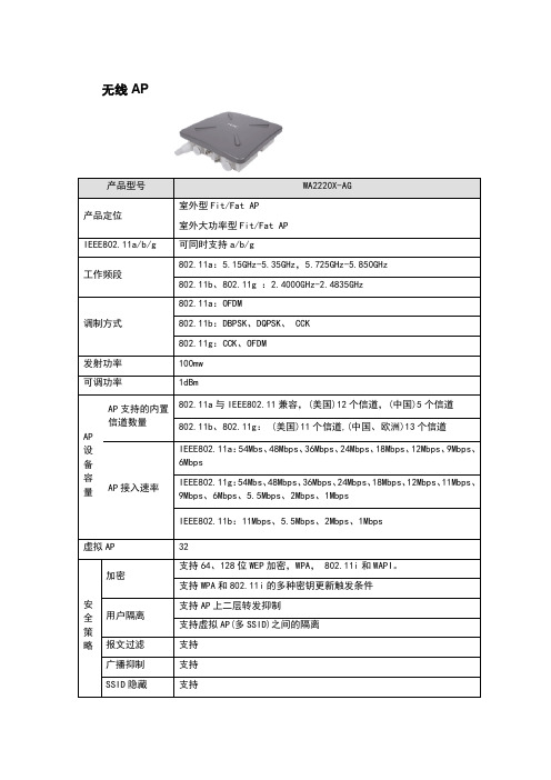
SSID隐藏
支持
认证
支持802.1X认证、MAC地址认证、PPPoE认证
支持WAPI认证
支持预认证、重认证
MAC地址过滤
支持
基于时间的计费
支持
实时计费
支持
认证和计费分离
支持
切换
AP间切换
支持,同时支持链路完整性特性
切换依据
根据信号强度、误码率、邻近AP是否正常工作等
链路预切换
支持轨道交通应用中AP间链路预切换技术
515ghz535ghz5725ghz5850ghzwa2220xag支持8021x认证mac地址认证pppoe认证认证支持wapi认证支持预认证重认证mac地址过滤基于时间的计费实时计费认证和计费分离ap间切换切切换依据换链路预切换mac地址学习二层桥vlan接支持支持支持支持支持同时支持链路完整性特性根据信号强度误码率邻近ap是否正常工作等支持轨道交通应用中ap间链路预切换技术支持支持vlan区分管理数据和用户数据支持基于接口的vlan基于8021q的vlan基于用户类的vlan基于ssid的vlan标记支持vlan过滤三层路由协议功ipv6能acl80211e优先级支持优先级队列及映射服流量限制务质流分类量qos策略映射用户数负载均衡支持支持支持不同ssidvlan映射不同的qos策略支持ip地址设置支持静态ip地址支持dhcp获取ip地址支持静态路由支持支持支持wmm支持以太网口支持8021p识别和标记流量负载均衡支持省电模式管理网络管理支持snmpv1v2v3traptr069fatap时基于windows平台上的配置工具
支持WMM
优先级
支持以太网口支持802.1p识别和标记
支持优先级队列及映射
流量限制
瑞友天翼-硬件环境配置建议
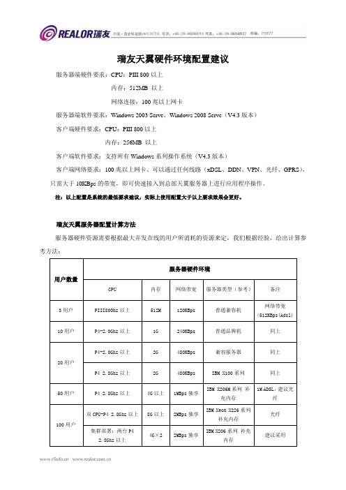
瑞友天翼硬件环境配置建议
服务器端硬件要求:CPU:PIII 800以上
内存:512MB 以上
网络连接:100兆以上网卡
服务器端软件要求:Windows 2003 Serve、Windows 2008 Serve(V4.3版本)
客户端硬件要求:CPU:PIII 800以上
内存:256MB 以上
客户端软件要求:支持所有Windows系列操作系统(V4.3版本)
客户端网络要求:100兆以上网卡、可以通过任何线路(xDSL、DDN、VPN、光纤、GPRS),只需大于10KBps的带宽,即可快速接入到总部天翼服务器上进行应用程序操作。
注:以上配置是系统的最低要求建议,实际上使用配置大于以上要求效果会更好。
瑞友天翼服务器配置计算方法
服务器硬件资源需要根据最大并发在线的用户所消耗的资源来定,我们根据经验,给出计算参考方法:
说明:GWT System 服务端所需内存配置参考,公式:
1)所需内存=操作系统所需内存(按512M计算)+天翼系统所需内存(30M计算)+每个登录应用所占内存×登录数量+256M(冗余)以上;
2)如并发用户数超过50个,建议使用双核CPU,天翼支持双核;
3)天翼程序只需30兆硬盘空间,如需要记录日志,一般10G即可周转。
H C产品清单 月

9801A0CM EWP-WA2620i-AGN
9801A0D0 EWP-WA2620
9801A0E7 EWP-WA2612 9801A0KM EWP-WA2610-GNE 9801A0KK EWP-WA2610-GN 9801A0FA EWP-WA2620-AGN 9801A0KW EWP-WA2620-AGN-C
S001A09L 无线PoE注入器
S101A42Q
无线PoE注入器 主 设备
0235A0S2 EWP-WP2008 0235A0S3 EWP-WP2016 0235A0S4 EWP-WP2024 0235A0S5 EWP-WP5024
0235A0X2 EWP-WP5008
S101A42R 0231A320
2,800.00 650
180 240
70
34 174 106
40 130
H3C 单端口大功率POE注入单元(含36W电源,千兆,推荐配套室外型设备使用)
480
射频电缆-1.2m-(N50直公)-(COAX-LMR240黑)-(N50直公) 射频电缆-1.2m-(N50直公)-(COAX-LMR240黑)-(RSMA50直母)
48
射频电缆-4.5m-50ohm-N50直公-(COAX-RG8/U)-N50直公
140
射频电缆-10m-50ohm-N50直公-(COAX-RG8/U)-N50直公
235
射频电缆-6.1m-50ohm-N50直公-(COAX-RG8/U)-反极性SMA直母
155
射频同轴连接器-N-50ohm-直式-母-配接带N型头的电缆-双阴转接器,外壳镀三元合 金
2701A00M C5060-510002-A
网络保护器CM52产品说明说明书

V12-T19-119Network ProtectorsCM52 Network Protector19Network ProtectorsProduct Description . . . . . . . . . . . . . . . . . . . . . . . . . . . . . . . . . . . . . . V12-T19-2Product History . . . . . . . . . . . . . . . . . . . . . . . . . . . . . . . . . . . . . . . . . . V12-T19-2Product History Time Line. . . . . . . . . . . . . . . . . . . . . . . . . . . . . . . . . . V12-T19-2Replacement Capabilities . . . . . . . . . . . . . . . . . . . . . . . . . . . . . . . . . . V12-T19-3Technology Upgrades—Relays and Communications . . . . . . . . . . . . . V12-T19-3Further Information . . . . . . . . . . . . . . . . . . . . . . . . . . . . . . . . . . . . . . . V12-T19-4Pricing Information . . . . . . . . . . . . . . . . . . . . . . . . . . . . . . . . . . . . . . .V12-T19-41919Network ProtectorsRetro-Build, Replacement Parts and RelaysNetwork ProtectorsOriginally aWestinghouse ProductCM-22CMDCM52Product DescriptionCutler-Hammer®networkprotectors from Eaton’selectrical business are specialself-contained air breaker unitshaving a full complement ofcurrent, potential and controltransformers, as well asrelay functions. The networkprotector enables theparalleling of two or moreprimary feeders on the samelow voltage bus. They areavailable for transformermounting in submersible ornon-submersible housings,or suitable for mounting withina low voltage switchgearassembly. The protective relayautomatically closes theprotector if power flow isforwarded into the collectorbus. It also trips the protectorupon flow of reverse fault ormagnetizing currents.Product HistoryThe network protector productline began manufacturing in1922 under the name ofWestinghouse Electric andManufacturing Company.Over the years a number ofdifferent production modelswere produced. The mostwidely installed model is thetype CM-22, which was firstmarketed in 1934 and is stillmanufactured today.New production CM-22,CMD, CMR-8 and CM52units are available fromthe Greenwood, SC, facility.Renewal parts are alsoavailable for these units.The old typeelectromechanical relayswhich have a large installedbase, are field replaceablewith the current solid- stateType MPCV relays.Eaton has also developedparts and relays to supportold style GE Type MG-8 andMG-9 network protectors. GEdiscontinued the manufactureof these products in 1996.Product History Time LineV12-T19-2V12-T19-31919Network ProtectorsRetro-Build, Replacement Parts and RelaysReplacement CapabilitiesNewSeveral current Cutler-Hammer production designs of network protectors are available:●CM52●CMD ●CMR-8●CM-22Retro-BuildRetro-building is a complete reworking of all the major components of a network protector including preliminary inspection, rebuilding, and re-testing equipment. Included in the process: removing all asbestos materials (where applicable), applying a new wiring harness, rebuilding the complete mechanism with motor and shunt trip, replacing the relay panel and completely reconditioning any enclosure. Modern components change the “as built” vintage to current production designs.Cutler-Hammer and Westinghouse ●CM-22●CMD ●CMR-8General Electric ®●MG-8●MG-9RetrofitGeneral Electric MG-8 and MG-9 network protectors up to 2000A are retrofittable with a new CM52 roll-in replacement breaker. This retrofitting option usesexisting enclosures and bus, replacing the remaining with the most recent technology of the CM52.CMD style network protectors are retrofittable with a new CM52 drawout circuit breaker and is available for all ampere ratings and voltages.Contact the Network Protector Group for additional information and availability at 1-800-525-6821 or 1-877-737-8328.Technology Upgrades—RelaysElectromechanical and older solid-state relays can be replaced with new micro-processor MPCV designs. The MPCV network relay can be field installed into ANY network protector regardless of the age or the manufacturer. Field installation is accomplished without breaker modification or any rewiring of the breaker control harness.Communications CapabilityThe MPCV relay has the capability of communicating information over a wide range of media.Hardwire (fiber or twisted pair), wireless (cellular or radio) are options available using Eaton’s VaultGard Communication platform. This system provides data for extensive engineering analysis, vault diagnostics, preventive maintenance and additionally provides DNP 3.0 objects direct to a SCADA system.MPCV Relay for Cutler-Hammer and Westinghouse Network ProtectorsFront ViewRear ViewMPCV Relay forGE Network ProtectorsFront ViewRear View1919Network ProtectorsRetro-Build, Replacement Parts and RelaysPartsEaton offers an extensiveinventory of newlymanufactured renewalparts for the followingnetwork protectors:Cutler-Hammer andWestinghouse●CM-22●CMD●CMR-8●CM52General Electric●MG-8●MG-9Test SetsHWT-500 Test KitThe HWT-500 test kit isoffered to provide completetesting capabilities fornetwork protectors with 208through 480V delta or wyeconnected systems. This issupplied in a rugged, wheeledcase with retractable handle.TrainingThe product line offers thefollowing network protectortraining seminars:●Safety and MaintenanceSeminar—This two-day seminar coversfundamentals of networksystems, network relayhistory and theory andmaintenance overview ofthe CM-22, CMD, CM52and MPCV relay●T roubleshooting NetworkProtector Seminar—This three-day seminarencompasses all materialincluded in the safety andmaintenance seminarand also covers theGE network protectors.A combination ofclassroom and hands-ontroubleshooting areprovidedFurther InformationPricing InformationCall Eaton’s NetworkProtector Group inGreenwood, SC.Toll Free: 1-800-525-6821or 1-877-737-8328.Publication Number DescriptionCM-22DB 35-550G Descriptive BulletinRPD 35-550H Renewal Parts Data BookRP02401002E Renewal Parts GuideIB 35-5001E Instruction BookCMDDB 35-552B Descriptive BulletinRPD 35-552Renewal Parts Data BookRP02401001E Renewal Parts GuideIB 35-552-G Instruction BookCMR-8RPD 35-575(E)Renewal Parts Data BookIB 35-575-A Instruction BookCM52B.52.01.S.E Sale BrochureIB 52-01-TE Instruction BookMPCR RelayIB 35-581A Instruction BookMPCV RelayIB 35-581B Instruction BookST-156Sales Engineer’s NotesSA-376Sales Aid MPCV RelaySA.52.01.S.E T&D Reprint—Pepco SystemHWT-500 T est KitIB 35-557Instruction BookLWT-450 T est KitIB 35-556-C Instruction BookSA-11898Sales AidV12-T19-4V12-T19-51919Network ProtectorsRetro-Build, Replacement Parts and RelaysCMD Network Protector Renewal PartsEaton’s Cutler-Hammer CMD Network ProtectorDescriptionCurrentCatalog NumberElectrical Components Finger cluster assembly (800–1875A)593C841G01Finger cluster assembly (2000–3000A)682C347G02Micro-switch assembly436B162G01Anti-close coil and switch (800–1875A)436B169G01Anti-close coil and switch (2000–3000A)436B169G02Auxiliary switch assembly (800–3000A)591C950G01Anti-close relay assembly 765A881G03Motor close relay765A880G01Trip coil assembly (1875–3000A)8230A23G02Trip coil only 677C903G03Capacitor only 8310A96H01BN dummy plate (CMD)435D857G03CNJ dummy plate (CMD)508B559G01Mechanical DevicesMotor assembly—two lead only (800–3000A)437B494G01Operations counter592C040H02Levering-in assembly (800–1875A)442D145G01Levering-in assembly (2000–3000A)6897D33G01HardwareNetwork relay hold-down nuts 5765A44G01Combination nuts 1087024Breaker crank589C063G01X-washer and contact grease kit 8264A32G01Breaker rollers 349A473H01Breaker blocking bar3670A85H01Breaker contact test gauge (1875A)3670A81G01Control Resistors and Rectifiers Diode 8310A96H03Rectifier3615A35H01Electromechanical resistor assembly 664A956G013100 ohm resistor 499A067H04Motor close rheostat8230A16G01Fuses (125–216V and 277/480V)NPL fuse (800A)140D318G04NPL fuse (1200A)140D318G05NPL fuse (1600–1875A)140D318G01NPL fuse (2000–2825A)140D318G02NPL fuse (3000A)140D318G06T ransformersCurrent transformer (multi-ratio: 800/1200/1600A)8230A85H01Current transformers (2000A)8313A73G02Current transformers (2500A)8313A73G01Current transformers (3000A)8313A73G03Potential transformer 7526A14G01Control power transformer8230A18H01DescriptionCurrentCatalog NumberCurrent Carrying Components Moving arcing contact (800–1875A)695C128G02Moving arcing contact (2000–3000A)695C134G01Stationary arcing contact assembly (800–1875A)593C842G01Stationary arcing contact assembly (2000–3000A)6897D10G02Arc chute (800–1875A)6914D18G02Arc chute (2000–3000A)9147D18G01Enclosure Parts—NEMA and Submersible (800–3000A)Fuse housing (800–1875A)595F152G01Fuse housing (2000–3000A)693C719G01Spade terminal (800–1875A)437B477G01Stud terminal (800–1875A)589C074G01Spade terminal (2000 – 3000A)690C292G01Stud terminal (2000–3000A)506B827G01Fuse housing cover with gasket (800–1875A)6390C82G01Fuse housing cover with gasket (2000–3000A)6390C84G01Fuse housing cover with window (800–1875A)592C092G01Fuse housing cover with window (2000–3000A)592C092G02Fuse housing tank gasket (800–1875A)505B339H01Fuse housing tank gasket (2000–3000A)590C508H018-point stationary secondary contact591C497G018-point moving secondary contact (breaker mounted)591C498G0612-point moving secondary contact (breaker mounted)693C618G0112-point stationary secondary contact 9246C47G01Door hinge and clamp kit (open side)6418C71G01Door hinge and clamp kit (hinge side)6418C71G02Hinge bolt only 1640799Tank window kit 545B314G02Tank window only 310C536H12Tank window gasket only5863A16H01Submersible T ank Door Gasketing Flat molded, pre 12/87 (800–1875A)437C089H01Flat molded, pre 12/87 (2000–3000A)590C512H011.25-inch (31.8 mm) diameter tubular Sep. MDT.—166 inches (4216.4 mm) (800–1875A)8309A37H011.25-inch (31.8 mm) diameter tubular Sep. MDT.—140 inches (3556.0 mm) (800–1875A)8309A37H021.25-inch (31.8 mm) diameter tubular Sep. MDT.—152 inches (3860.8 mm) (2000–3000A)8309A37H01Flat molded, pre 12/87 (2000–3000A)437C089H01Barrier assembly tanking (800–1875A)567F830G01Barrier assembly tanking (2000A plus)693C717G021919Network ProtectorsRetro-Build, Replacement Parts and RelaysCM-22 Network Protector Renewal PartsEaton’s Cutler-Hammer CM-22 Network ProtectorDescriptionCurrentCatalog NumberElectrical ComponentsMotor contactor assembly (replaces G01, G02 and SG relay)503B286G03“J” switch assembly (664A948H01)1572037“J” switch contact only657A239H01Motor cutoff “W” switch assembly (for three lead motor)310C629G01Motor cutoff “W” switch assembly (for two lead motor)310C629G03Auxiliary switch 12-pole 46A5916G13 + G14310C626G02Auxiliary switch eight-pole (replaces type “W”)310C626G03Network relay terminal block (lower)310C356G05Network relay terminal block (upper)310C356G03CNJ terminal block310C356G02BN terminal block (lower)310C356G01BN terminal block (upper)310C356G04BN dummy plate435D857G03CNJ dummy plate508B559G01Mechanical DevicesMotor—three lead592C071G03Motor—three lead with amp plug 592C071G01Motor—two lead592C071G02Shunt trip device (208V)1114739Shunt trip device (250V)1630111Shunt trip coil only (208V)0918738Shunt trip coil only (250V)1041078Operations counter592C040H03HardwareMechanical links, springs and caps8312A08G01Fuse disconnect nut1087025Fuse disconnect nut1087024Relay combo nut (large)5765A44G01Overtoggle link assembly436D164G02Micarta® link (left side of overtoggle assembly)1572053Micarta link (right side of overtoggle assembly)1572054Operating handle17B9956G01Mechanism bumper and pins pack (sold in packs of three)6419C75G01Control Resistors and RectifiersPhasing resistor—3 ohm499A067H05Phasing resistor—3100 ohm499A067H04Motor circuit—3 ohm resistor assembly664A956G02Motor circuit—3 ohm fixed and adjustable resistor assembly664A956G01T ransformersLighting transformer assembly (250V)542B075G01Lighting transformer assembly (125V)542B075G02Potential transformer (single only, six required in assembly)7526A14G01Potential transformer assembly (left and right)60A3930G03Control power transformer (sold separately)8234A01G01Control power transformer with mounting kit508B560G02DescriptionCurrentCatalog NumberCurrent T ransformersMulti-ratio 1600/1200/800A:5A745C148G01Fixed ratio 1600A:5A592C554G01Fixed ratio 2000A:5A6109C13G01Fixed ratio 2500A:5A592C556G01Fixed ratio 3000A:5A592C557G01Current Carrying ComponentsStationary conductor (800–1875A, left and right)310C352G02Stationary conductor (800–1875A, center)310C352G01Stationary main contact assembly (2000–3000A, includes arcing contact)310C358G02Stationary main contact assembly (3500A, includes arcing contact)310C358G01Moving contact (800–1875A, left and right)310C353G01Moving contact (800–1875A, center)310C353G02Moving contact assembly (2000–3500A, right)436D166G01Moving contact assembly (2000–3500A, left and center)436D166G02Arcing contact moving (2000–3500A)09A2605G05Arcing contact stationary (800–1875A)1529542Arcing and main stationary contact assembly (2000–3500A)310C357G01Arc chute (all sizes)17B9967G01Enclosure Parts—NEMA and SubmersibleBreaker barrier kit (800–1875A)6549C10G01Breaker barrier kit (2000–3000A)6914D10G014-point stationary disconnect device (left hand)678C170G034-point stationary disconnect device (right hand)678C170G04Moving disconnect device (left hand)678C169G02Moving disconnect device (right hand)678C169G03Round sight glass kit (tempered glass)545B314G02Door hinge and clamp kit (open side)6418C71G01Door hinge and clamp kit (hinge side)6418C71G02Submersible T ank Door Gasketing0.75-inch (19.1 mm) diameter tubular, pre '62 only—139 inches (3530.6 mm) (800–1875A)8311A01H011.25-inch (31.8 mm) diameter tubular—139 inches (3530.6 mm) (800–1875A)6337C85H401.25-inch (31.8 mm) diameter tubular— 61 inches (4089.4 mm) (2000–3000A)6337C95H401.25-inch (31.8 mm) diameter tubular—181 inches (4597.4 mm) (2000–3000A)6337C97H40V12-T19-6。
UT525 UT526 说明书

I. OverviewUT525/UT526 is a multifunction digital instrument adopting brand-new design using large-scale integrated analogue and digital circuits and micro-processor chip. It mainly measures RCD parameters, low-resistance continuity, insulation resistance,DC&AC Voltage, etc. The versatile functionality, high accuracy and ease of use features make it widely used to measure insulation and continuity of various kinds of electrical equipments, and an ideal tool for maintenance, inspection and tests badly needed for RCD in those equipments.II. Safety InformationThis instrument was designed, manufactured and tested according toIEC61010 safety standard (Safety Requirements for Electrical Equipment). The manual includes safety information related to the safe operation of the instr -ument. Please read the following instructions before use and strictly follow them during the operation.W arning● Please read and understood the manual before using the instrument.● Use the instrument as specified in the manual and keep the manual well for future reference.● Misuse may cause personal injury or damage to the instrument during tests.Sign on the instrument indicates users to refer to the manual for details in order to ensure safe operation of the instrument.DangerWarning. CautionIII. Electrical SymbolsIV. SpecificationsAccuracy: ±(a% of reading+ b digits), calibration per year Ambient Temperature & Humidity: 23±5℃, 45~75%RH.RCD TestTest current 10mA 30mA 100mA 300mAApplied voltageVoltage: 220V±10%, frequency: 45Hz-65Hz Test current accuracy At 220Vac ± 2: 0 +10%Trip timeAccuracy ±(5%+2)(10mA) range: 0-2,000mS (30mA) range: 0-500mS(100mA) range: 0-300mS(300mA) range: 0-300mS Insulation Resistance(UT525)Rated voltage 100V 250V 500V Test range 0.05MΩ-200MΩOpen circuit voltage DC 100V±10% DC 250V±10% DC 500V±10% Rated test current 100KΩ load 250KΩ load 500KΩ loadShort-circuit current <1.8mAAccuracy 0.05MΩ-200MΩ: ±(5%+5)0.9mA-1.1mA 0.9mA-1.1mA 0.9mA-1.1mA Rated voltage 250V 500V 1,000V Test range 0.05MΩ-200MΩ 0.05MΩ-300MΩ 0.05MΩ-500MΩ Open circuit voltage DC 250V±10% DC 500V±10% DC 1,000V±10% Rated test current 500KΩ load 1MΩ load 250KΩ loadShort-circuit current <1.8mAAccuracy 0.05MΩ-500MΩ: ±(5%+5)0.9mA-1.1mA 0.9mA-1.1mA 0.9mA-1.1mA Voltage DCV ACVTest range ±0-±440V 0-440V (50/60Hz), for <10V, it is for reference only. Resolution 1VAccuracy±(2%+3)FrequencyTest range 20Hz-100Hz Resolution 1HzAccuracy Just for reference● Display: LCD display, max reading: 9999● Low battery indication: ● Over limit indication: “OL ”● Auto range function ● Unit display: Display function and unit symbols simultaneously.● Work conditions: 0℃-40℃/ ≤85%RH ● Storage condition: -20℃-60℃/≤90%RH ● Dimensions: 150mm(L)×100mm(W)×71mm(D)● Current consumption: about 50mA (1,000V output) (about 10mA in general condition)● Accessories: test lead, alkaline battery (1.5V, AA)×6, manual, carrying bag ● Weight: 0.7kg (including batteries)● Power: alkaline battery (1.5V, AA)×6V . Tester Description (Front View, See Figure 1)1. L : Live terminal for RCD measurement and positive terminal for voltage measurement2. E : earth terminal for RCD measurement3.N : Neutral terminal for RCD measurement and input negative terminal for voltage tmeasurement4. LINE : High voltage output terminal for insulation resistance measurement5. LCD6. RCD current setup/voltage switchover button7. RCD phase angle switchover/zeroing button8. Test button Figure 1VI . Buttons and Rotary Switch Functions1. I/VOLT: Select RCD test currents/switch between AC and DC voltage;2. ANG/ZERO: Switch phase angle for RCD measurements/ reset to zero before continuity test;3. TEST: Begin a test;4. Set rotary switch to Continuity: Test for grounding continuity;5. Set rotary switch to RCD/V: Measure RCD/AC&DC voltage;6. Set rotary switch to 100V/250V/500V (UT525) or 250V/500V/1000V (UT526): select a output voltage under insulation resistance measurement.VII. Preparations before MeasurementWhen the instrument turns on, if low battery indicator shows on left side of LCD,it indicates the battery is running out and please replace the battery timely.VIII. Testing for Continuity(See Figure 2)Multifunction Electric Testers● Do not measure any circuit with voltage above 440Vac or 440Vdc.● Do not take measurements on sites exposed to flammables, for spark may cause the explosion.● Do not use the Tester if it is wet or the operator’s hands are wet.● Do not touch conductive parts of test leads during measurement.● Do not use the instrument if it works abnormally. Eg: the instrument is damaged or the metal is exposed.● Please take caution when working voltage exceeds 33Vrms, 46.7Vacrms or 70Vdc, for it may cause electric shock.● The electric storage in tested circuits must be released after finishing high resistance measurements.● Do not replace the battery if the instrument is under wet conditions.● Please ensure the test leads are firmly secured to input terminals of the instrument.● Ensure the instrument is turned off before opening the battery cover.● The tested circuit should be discharged completely and totally separated from the power before making resistance measurements.● If it is necessary to replace the test leads or power adaptor, please use only ● If low battery indicator( ) shows, stop using the instrument. Take ● Do not store or use the instrument in the places exposed to high temperature, high humidity, explosives, flammables or strong electromagnetic field.● Clean the instrument casing with dampened cloth and mild detergent. No abrasives or solvents are allowed.● When the instrument is wet, dry it first before storing it.Insulation Resistance(UT526)● Auto voltage release ● Red warning light ● Compliances: CATIII 600V, Pollution Degree II as per IEC61010● Do not measure with the battery cover opened.● Do not touch any circuit under test when you are measuring insulation or RCD.9. Rotary switchTo test continuity:1. Connect the tested object and the Tester as shown in Figure 2;2. Set the rotary switch to Continuity;3. Press TEST button to begin the test;Caution:● To ensure the test accuracy, please short-circuit the test leads and zero the display(Zeroing Steps: set the tester under continuity status, short-circuit the test leads, press TEST button and then press ANG/ZERO button to reset the resistance of test leads to “0”, ZERO shows on LCD.)● Do not test any live objects.Figure 2IX. Measuring RCD(See Figure 3)Caution:Caution:Figure 3XMeasuring Voltage (See Figure 4)Figure 4XI. Measuring Insulation Resistance (See Figure 5)CautionFigure 5XII. Replacing the Battery(See Figure 6)Caution● Do not use old and new batteries at the same time.● Pay attention to the polarity during replacing battery.Danger1. To avoid potential electric shock, remove the test leads away from the instrument before replacing battery.2. Do not measure with the battery opened.3. When sign “ ” is displayed on LCD, it means the battery needs to be replaced.Figure 6XIII. MaintenanceCleaning the Housing:●Wipe the surface with soft wet cloth or sponge.● To avoid instrument damage, do not dip the instrument into water.● When the instrument is wet, make it dry and then store.● When the instrument needs to be checked or repaired, please have it serviced by qualified professional personnel or designated service center.The content is subject to change without prior notice.**END**To measure RCD,1. Set the rotary switch to RCD/V;2. Press I/VOLT button to set up test current (available: 10mA/30mA/100mA/ 300mA);3. Insert supplied test leads (with power plug) to the Tester (Red-L; Green-E; Blue-N) and plug the plug into 220V civil socket;4. Press TEST button to start.● Ensure the power socket is reliably grounded when measuring RCD.● Ensure the power socket Live, Neutral and Earth lines are properly connected when measuring RCD.● Please take caution when taking RCD measurements, for they are all done under high voltage status.To measure voltage:1. Set the rotary switch to RCD/V;2. Long press I/VOLT to switch between AC and DC mode;3. a. Insert test leads into input terminals (Red to L, Black to N) and connect Red & Black clips or probes to tested circuit.b. Or Insert the special test leads (with plug) to the input terminals (Red to L, Green to E, Blue-N) and plug the plug into the tested socket.4. Press TEST button, the Tester will automatically detect out AC/DC mode and display the voltage and frequency readings on LCD.● Do not input any voltage higher than 440V or 440Vrms, although it may be possible to display a higher voltage, it may damage the instrument.● To avoid electric shock, please take caution when measuring high voltage.● After completing the measurements, remove test leads away from tested circuits and disconnect them from the input terminals of the instrument.● Do not measure with the battery cover opened.● Make sure the tested circuit is dis-energized, completely discharged and totally separated from the power supply before measurement. Do not measure the insulation resistance of live equipments or lines.● Do not measure with the battery cover opened.● Do not short-circuit the test leads under high-voltage output status or prepare to measure insulation resistance after the high voltage has already been output.● After the measurement finishes, do not touch the tested circuit, for the storedcapacitance in the circuit may cause electric shock.● Do not touch the test leads even after they are removed away from the circuit, wait until the test voltage is totally released.To measure insulation resistance:1. Turn the rotary switch to one of 100V/250V/500V (UT525) or 250V/500V/ 1000V (UT526) test voltage.2. Insert test leads into input terminals (Red to LINE, Black to N) and connect them to the tested circuit. High voltage is output from LINE terminal.3. Continuous Measurement: Press TEST button, the Tester will self-lock, output the test voltage and emit warning light simultaneously. With the measurement finished, press TEST to unlock and stop the continuous measurement.To replace the battery, follow the steps as below:1. Turn off the instrument (turn the rotary switch to off), and remove away the test leads.2. Unscrew the battery cover, take out the old batteries and replace with new 6 pcs batteries.3. Screw up the battery cover again.P/N:110401104486X DATE:2018.06.26 REV.5。
TL52426_PC+ASA_EN_2002.10
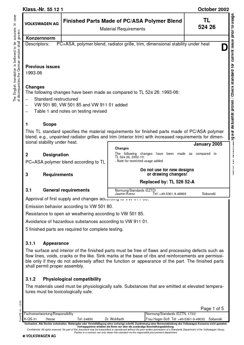
Vertragspartner erhalten die Norm nur über die zuständige Beschaffungsabteilung.Confidential. All rights reserved. No part of this document may be transmitted or reproduced without the prior written permission of a Standards Department of the Volkswagen Group.Parties to a contract can only obtain this standard via the responsible procurement department.© VOLKSWAGEN AGT h e E n g l i s h t r a n s l a t i o n i s b e l i e v e d t o b e a c c u r a t e . I n c a s e o f d i s c r e p a n c i e s t h e G e r m a n v e r s i o n s h a l l g o v e r n .Page 2TL 524 26: 2002-10D3.2 Manufacturing methodInjection molding3.3 Labeling according to VDA 260>PC+ASA<3.4 ConditioningPrior to testing, the specimens required for the individual tests must be conditioned for at least 48 h in the DIN 50 014 -23/50-2 standard climate.3.5 Validity of requirementsThe required numerical values apply to each individual measurement.4 Material requirements4.1 MaterialSee section 6.1. Polymer blend of polycarbonate and acrylic ester modified styrene acrylonitrile copolymer, UV-stabilized4.2 ColorAccording to drawing.5 Characteristics requirementsSee table 1.Table 1No. Property Unit Requirementg/cm³ 1.15 to 1.171 Densityacc. to DIN 53 479, buoyancy method2 Ball indentation hardnessN/mm² 130 ± 10acc. to DIN EN ISO 2039-1 andsection 6.2MPa ≥ 903 Flexural strengthacc. to DIN EN ISO 178 andsection 6.3kJ/m² No fracture.4 Impact resistanceacc. to DIN EN ISO 179-1 andsection 6.4kJ/m² ≥ 105 Notched impact strengthacc. to DIN EN ISO 179-1 andsection 6.5°C ≥ 1256 Dimensional stability under heat acc. toVicatacc. to DIN EN ISO 306, method B insilicone oilPage 3TL 524 26: 2002-106 Notes on testing6.1 MaterialThe identity test is performed by infrared spectroscopy.6.2 Ball indentation hardnessThe measurements must be taken on at least three (20 x 20) mm specimens (2 measurements per specimen). The grained surface of specimens which have been removed from finished parts with one-sided graining shall be removed using a surface grinding machine. The flat surface created in this way serves as the contact surface. The measurement is taken on the untreated back. Meas-urement period 10 s.6.3 Flexural strengthDetermination of the flexural stress at maximum load according to DIN EN ISO 178; deviating specimen length: (50 ± 1) mm; width: (6 ± 0.2) mm; thickness according to finished part thickness (up to max. 4 mm); support separation: 40 mm; support radius (1.0 to 1.2) mm; test rate: (14 ± 1) mm/min. Specimens taken from finished parts with one-sided graining are placed on the test ma-chine support so that the grained side faces the pressure fin.6.4 Impact resistanceImpact resistance test (broadside impact) according to DIN EN ISO 179-1; deviating specimen length: (50 ±1) mm; width: (6 ± 0.2) mm, thickness according to finished part thickness (up to max.4 mm); mounting flange interval (support separation): 40 mm, test apparatus pendulum impact tester 4J.Page 4TL 524 26: 2002-10DSpecimens removed from finished parts with one-sided graining shall be positioned on the pendu-lum impact tester support so that the grained side faces the direction of impact.6.5 Notched impact strengthImpact resistance test (broadside impact) according to DIN EN ISO 179-1; deviating specimen length: (50 ±1) mm; width: (6 ± 0.2) mm, thickness according to finished part thickness (up to max.4 mm); mounting flange interval (support separation): 40 mm, test apparatus pendulum impact tester 4J.The specimens are given a 0.8 mm wide U-shaped notch on the broad side. The notch depth shall be 1/3 the specimen thickness. The edges adjoining the notch root must have a curvature radius of < 0.1 mm.Specimens taken from finished parts with one-sided graining are notched on the grained side.6.6 Elevated-temperature behaviorAging at elevated temperatures according to DIN 53 497, method B, to be performed with at least one complete finished part. Aging duration (22 + 2) h; aging temperature (120 ± 1) °C.6.7 Low-temperature behaviorAging of at least one complete finished part in air at (-40 ± 1) °C; aging period: (22 + 2) h.6.8 LightfastnessIf the number of exposure periods is not defined in the drawing, the following rule applies:3 periods of exposure for components in areas with indirect sun radiation.5 periods of exposure for components in areas with direct sun radiation (e.g., door upper trim).10 periods of exposure for components in areas with maximum sun radiation (e.g., rear shelf).6.9 Impact resistance after artificial weatheringA minimum of 5 specimens, length (50 ± 1) mm, width (6 ± 0.2) mm, thickness according to product thickness (max. 4 mm), are artificially weathered for 200 h in a testing device according to PV 3930. The side of the specimen corresponding to the visible side of the finished part (functional side) is turned toward the light. Mutual contact with the narrow edge of the specimen is permissible. The impact resistance test to follow the artificial weathering is performed as under section 6.4. Here the specimens are placed on the mounting flange of the pendulum impact tester so that the unweathered side faces the direction of impact.7 Referenced standardsTL 1010 Materials for Vehicle Interiors, Burning Behavior; Material Requirements PV 1303 Non-Metallic Materials;Exposure Test of Passenger Compartment Compo-nentsPV 3930 Non-Metallic Materials; Weathering in Humid HeatVW 011 55 Vehicle Supply Parts – General; Approval of First Supply and ChangesVW 501 80 Vehicle Interior Components; Emissions BehaviorVW 501 85 Vehicle Components; Resistance to Open Air WeatheringVW 911 01 Environmental Standard for Vehicles, Vehicle Parts, Materials, Fuels;Avoidance of Hazardous SubstancesDIN 50 014 Climates and their Technical Application; Standard AtmospheresPage 5TL 524 26: 2002-10D DIN 53 479 Testing of Plastics and Elastomers; Determination of DensityDIN 53 497 Testing of Plastics; Heat Storage Test of Molded Articles Made of Thermo-plastic Molding Materials Without Outside Mechanical StressDIN EN 20 105-A02 Textiles; Tests for Color Fastness, Part A02: Gray Scale for Assessing Change in ColorDIN EN ISO 178 Plastics; Determination of Flexural PropertiesDIN EN ISO 179-1 Plastics; Determination of Charpy Impact Resistance Properties, Part 1: Non-Instrumented Impact Resistance TestDIN EN ISO 306 Plastics, Thermoplastic Materials; Determination of Vicat Softening Tem-peratureDIN EN ISO 2039-1 Plastics; Determination of Hardness, Part 1: Ball Indentation MethodVDA 260 Automotive Components; Identification of Materials。
dd-wrt固件支持的路由器型号
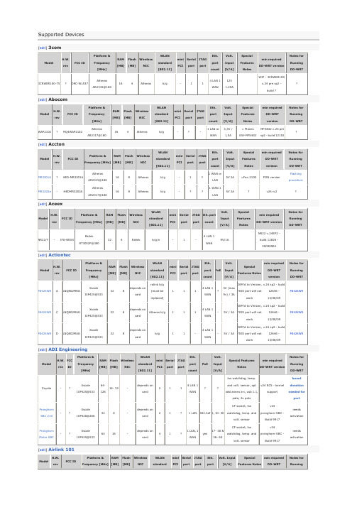
Pronghorn Metro SBC
-
?
Xscale IXP425@533
64
16
-
depends on card
4
1
?
1 LAN, 1 WAN
yes
17- 30 & 36- 60
CF socket, hw watchdog, temp. and volt. sensor
mini PCI
Serial port
JTAG port
Eth. port count
PoE
Volt. Input [V/A]
Special Features Notes
min required DD-WRT version
Notes for Running DD-WRT
Coyote
-
?
Xscale IXP425@533
v.24 sp2 - build 12646 - 13/08/09
MI424WR
MI424WR
C
LNQ802MAG
Xscale IXP425@533
32
8
depends on card
Atheros b/g
1
1
1
4 LAN 1 WAN
-
5V / 3A
OEM'd to Verizon, FIOS port will not work
clone ofdir-300
V24 RC5
[1]
AP431W
?
RRK-AP431W
Atheros AR2313A@180
16
4
Atheros
b/g
tl52625标准中文版

tl52625标准中文版
tl52625标准中文版介绍
tl52625标准中文版是针对电子设备无线通信性能测试而制定的标准,它规定了电子设备在无线通信方面的性能要求、测试方法、认证程序等。
该标准适用于各种类型的电子设备,包括智能手机、平板电脑、智能家居产品、物联网设备等。
一、主要内容
tl52625标准中文版主要包括以下几个方面的内容:
1. 无线通信技术要求:该标准规定了电子设备所采用的无线通信技术的性能要求,包括传输速率、信号质量、功耗等。
2. 电磁辐射标准:该标准规定了电子设备在运行过程中产生的电磁辐射的限值,以确保对环境的影响在可接受范围内。
3. 安全性能要求:该标准规定了电子设备的电气安全性能要求,包括过电流、过电压、静电等。
二、测试方法
tl52625标准中文版规定了电子设备无线通信性能测试的方法和程序,包括测试设备、测试流程、测试结果判定等。
测试机构需要按照标准要求进行测试,以确保电子设备的性能符合标准要求。
三、认证程序
tl52625标准中文版规定了电子设备无线通信性能认证的程序和要求,包括认证机构的选择、申请资料审核、测试过程监控、测试结果判定等。
认证机构需要按照程序要求进行认证,以确保电子设备的质量和性能符合标准要求。
总结
tl52625标准中文版是针对电子设备无线通信性能测试的重要标准,它规定了电子设备在无线通信方面的性能要求、测试方法、认证程序等。
该标准的实施将有助于提高电子设备的性能和安全性,同时保护环境免受电磁辐射的危害。
对于生产厂家来说,按照该标准进行生产和认证,将有助于提高产品的市场竞争力。
TL52652

分类号 55 12 1 2004.11页2TL 526 52:2004-11D3.1.1 坚韧稳定制成品必须在表面和在内部免于缺陷和错误制造,像流线,缩孔,撕裂诸如此类的. 变化在骨架和加固的方式的范围内是只允许的,当它不损害功能和外表. 完成部分必须许可一个完美的装配.3.1.2 人类承受力采用的材料必须是毫无疑问从生理学角度来看的. 有关于在更高的温度汽化的物质必须存在无毒害的.3.2 制造酒精铸造法.3.3 执行TL 526 52-A PC+ASA-混合聚合物和提高的热不变形性至+120度TL 526 52-B ASA-PC-混合聚合物, 标准型式,抗热至+100度3.4 标记根据VDA 260TL 526 52-A >PC+ASA<TL 526 52-B >ASA+PC<3.5 调节为了这个单独的考核必需的试验是在考核至少48小时之前在标准气候 DIN 50014-23/50-2下调节.3.6 评估测量结果要求的数值适用于每个单位计量.3.7 原材料看章节5.1.两个执行:用聚碳酸酯构成的混合聚合物和丙烯酸酯调整的苯乙烯-丙烯腈-共聚体, UV-稳定.3.8 色彩根据图样和/或者认可.页3TL 526 52:2004-11D 4.属性特征看表1表1页4TL 526 52:2004-11D5 试验提示5.1生产材料鉴定试验实现红外线光谱学.5.2 弯曲强度弯曲压力的规定在最大力的情况下根据DIN EN ISO 178, 然而试用长度(50±1) mm; 宽(6±0,2) mm;厚度根据产品厚度(最大4 mm); 柱基宽40 mm;支架半径1,0 mm至1,2 mm;试验速率(14±1)mm/min. 来自单方面的有纹理的制成品生产的样本是那样放置于测试机的支架上, 这样有纹理的那一面对着压锤显示.5.3 冲击韧性来自机械的原因和/或者为了试验大小和试验形式一个试验根据DIN EN ISO 179-1/1eA之前应该不能实现的,也能变成像接着的程序那样:冲击弯曲试验(宽边的冲击)根据DIN EN ISO 179-1, 然而样本长度(50±1) mm; 宽(6±0,2) mm;厚度根据产品厚度(最大4mm);底座距离(柱基宽)40mm; 测试仪摆式冲击试验 4J. 来自单方面的有纹理的制成品生产的探测器是那样放置于推力轴承的摆式冲击试验机上, 这样有纹理的那一面对着锤刃显示.然而这些需要协定.5.4缺口冲击韧性测试仪摆式冲击试验机 4J.来自机械的原因和/或者为了试验大小和试验形式一个试验根据DIN EN ISO 179-1/1eA之前应该不能实现的,也能变成像接着的程序那样:冲击弯曲试验(宽边的冲击)根据DIN EN ISO 179-1, 然而样本长度(50±1) mm; 宽(6±0,2) mm;厚度根据产品厚度(最大4mm);底座距离(柱基宽)40mm;探测器变得宽边的和一个0,88mm宽U型缺口装配. 缺口表现为1/3探测器厚. 缺口底邻接边缘必须显示一个圆形半径<0,1mm.在单方面的有纹理的制成品是在有纹理的那一面上的探测器来弄缺口,最后那样放置于推力轴承的摆式冲击试验机上,缺口中间准确地位于冲击面中. 从而接着留心,缺口位于锤刃的边之上.然而这些需要协定.5.5 热反应热储存试验根据DIN 53497操作过程B 最少的一个完整的制成品.储存持续时间(22+2)h.5.6 冷反应储存最少一个完整的制成品在空气中在(-40±1) ℃; 储存持续时间(22+2)h.5.7耐光性假如在图样中曝露时间的数目没有限制,适用如下的规则:-3个曝露时间对于设备在间接的日射的范围内-5个曝露时间对于设备在直接的日射的范围内(例如:门的栏杆)-10个曝露时间对于设备在最高的日射的范围内(例如: 汽车后备箱)5.8冲击韧性根据人造的风化样本长度(50±1) mm; 宽(6±0,2) mm;厚度根据产品厚度(最大4mm)最少5个样本在一个测试仪中根据PV 3930 200h 久的人工的使风化. 从而这样的探测面变得面向灯光, 制成品的可见的面相匹配(使用面). 一个样本狭边的相互的接触是从而被允许的. 人造的风化冲击韧性最后的试验是根据章节 5.4来实施.从而样本是那样放置于推力轴承的摆式冲击试验机上, 这样不风化的那一面对着锤刃显示.6参照的附件TL 1010 内部设备材料,燃烧特性; 原料要求PV 1303 非金属材料; 曝露试验对于汽车室内的设备PV 3930 非金属材料; 风化在湿润的温暖的环境中VW 011 55 汽车-供应件通常地; 原先的供货和改变的批准VW 501 80 汽车室内的设备; 排放特性VW 501 85 汽车设备; 无风化持久性VW 501 90 汽车内部设备的装备; 色彩格律的评价VW 911 01 汽车的环境标准,汽车零配件,原料,生产原料; 污染物质的避免DIN 50014 气候的和它的科技的应用; 一般的气候DIN 53497 塑料的试验; 热储存试验在模制件来自热塑性的材料或者外部的机械的要求. DIN EN 20105-A02 纺织品; 不褪色试验, 部分A02; 灰色标准样板为了色彩改变的评估DIN EN ISO 178 塑料; 弯曲特性的测定DIN EN ISO 179-1 塑料; Charpy-打击的测定-部分1: 不装配的冲击韧性试验DIN EN ISO 306 塑料; 热后可塑性, Vicat-耐热变形温度的测定DIN EN ISO 1183-1 塑料; 程序为了塑料的密度测定-部分1: 浸没于液体中的程序,程序伴随着流动性液体比重计和滴定程序.VDA 260 机动车的设备; 材料的标记符号.纸条上的:有效的从-40℃至90℃温度稳定的从-40℃至130℃(2,4两句应该不是德语)。
- 1、下载文档前请自行甄别文档内容的完整性,平台不提供额外的编辑、内容补充、找答案等附加服务。
- 2、"仅部分预览"的文档,不可在线预览部分如存在完整性等问题,可反馈申请退款(可完整预览的文档不适用该条件!)。
- 3、如文档侵犯您的权益,请联系客服反馈,我们会尽快为您处理(人工客服工作时间:9:00-18:30)。
Confidential. All rights reserved. No part of this document may be transmitted or reproduced without the prior written permission of a Standards Department of the Volkswagen Group.Parties to a contract can only obtain this standard via the responsible procurement department.© VOLKSWAGEN AGT h e E n g l i s h t r a n s l a t i o n i s b e l i e v e d t o b e a c c u r a t e . I n c a s e o f d i s c r e p a n c i e s t h e G e r m a n v e r s i o n s h a l l g o v e r n .Page 2TL 526 52: 2004-11D3.1.1 AppearanceThe surface and interior of the finished parts must be free of flaws and processing defects such as flow lines, voids, cracks or the like. Sink marks at the base of ribs and reinforcements are permissible only if they do not adversely affect the part's function or appearance. The finished parts shall permit proper assembly.3.1.2 Physiological compatibilityThe materials used must be physiologically safe. Substances that are emitted at elevated temperatures must be toxicologically safe.3.2 ManufactureInjection molding method.3.3 TypesTL 526 52-A PC+ASA polymer blend with increased dimensional stability under heat up to +120 °CTL 526 52-B ASA+PC polymer blend, standard type, with dimensional stability under heat up to +100 °C3.4 Identification according to VDA 260TL 524 52-A >PC+ASA<TL 526 52-B >ASA+PC<3.5 ConditioningPrior to testing, the specimens required for the individual tests must be conditioned for at least 48 h in the DIN 50014-23/50-2 standard climate.3.6 Evaluation of the measuring resultsThe required numerical values apply to each individual measurement.3.7 MaterialSee Section 5.1.Both types: polymer blends of polycarbonate and acrylic ester modified styrene acrylonitrile copolymer, UV-stabilized3.8 ColorAccording to drawing and/or release.Page 3TL 526 52: 2004-11D 4 PropertiesSee Table 1.Table 1No.Property Unit RequirementType A Type B1 Density acc. to DIN EN ISO 1183-1,buoyancy methodg/cm3 1.15 to 1.17 1.11 to 1.15 2 Flexural strength acc. to DIN EN ISO 178see Section 5.2MPa 90 803 Impact resistanceacc. to DIN EN ISO 179-1test method 1/eUsee Section 5.3kJ/m2No fracture4 Notched impact strengthacc. to DIN EN ISO 179-1test method 1/eAsee Section 5.4kJ/m2 45 85 Notched impact strengthacc. to DIN EN ISO 179-1see Section 5.4kJ/m2 106 Dimensional stability under heat acc. toVicat and DIN EN ISO 306, method B50°C 125 1067 Elevated-temperature behavior acc. toDIN 53497see Section 5.57.1 Aging temperature (120 ± 1) °C The finished partsmust exhibit nochange in form,color or surfaceappearance.-7.2 Aging temperature (90 ± 2) °C - The finished partsmust exhibit nochange in form,color or surfaceappearance.8 Low-temperature behaviorsee Section 5.6 The finished parts shall remainfully functional at low temperatures; there shall be no damage. They shall not exhibit cracks or other damages, neither at low temperatures nor after subsequently raising the temperature to +23 °C. Refer to drawing for special requirements.9 Lightfastness acc. to Test SpecificationPV 1303see Section 5.7(Requirement only applies to visible partsin the vehicle interior or if specified in thedrawing.)Number of exposure periods accordingto drawing. The exposed surface shall not exhibit changes as comparedto the as-received condition, such as change in color, chalking and/or cracking.Gray-scale level 4 acc. toDIN EN 20105-A02.Page 4TL 526 52: 2004-115 Notes on testing5.1 MaterialThe identification test is performed using infrared spectroscopy.5.2 Flexural strengthDetermination of the flexural tension at maximum load according to DIN EN ISO 178, however, specimen length (50 ± 1) mm; width (6 ± 0.2) mm; thickness corresponding to product thickness (up to max. 4 mm); support separation 40 mm; bearing surface radius 1.0 mm to 1.2 mm; test rate (14 ± 1) mm/min. Specimens taken from finished parts with one-sided graining shall be placed on the bearing surfaces of the testing device in such a manner that the grained side faces toward the pressure fin.5.3 Impact resistanceIf, for reasons concerning the devices and/or the specimen size and shape, a test according to DIN EN ISO 179-1, test method 1/eU, proves to be impossible, the following procedure can be implemented as an alternative:Impact resistance test (broadside impact) according to DIN EN ISO 179-1, however, specimen length (50 ± 1) mm; width (6 ± 0.2) mm; thickness corresponding to product thickness (up to max. 4 mm); mounting flange spacing (support separation) 40 mm; pendulum impact tester 4J. Specimens taken from finished parts with one-sided graining shall be positioned on the mounting flange of the pendulum impact tester with the non-grained side opposing the direction of impact. However, this is subject to prior agreement.Page 5TL 526 52: 2004-11D5.4 Notched impact strengthPendulum impact tester 4J.If, for reasons concerning the devices and/or the specimen size and shape, a test according to DIN EN ISO 179-1, test method 1/eA proves to be impossible, the following procedure can be implemented as an alternative:Impact resistance test (broadside impact) according to DIN EN ISO 179-1, however, specimen length (50 ± 1) mm; width (6 ± 0.2) mm; thickness corresponding to product thickness (up to max. 4 mm); mounting flange spacing (support separation) 40 mm.The specimens are given a 0.8 mm wide U-shaped notch on the broad side. The notch depth shall be 1/3 of the specimen thickness. The edges adjoining the base of the notch must have a curvature radius of < 0.1 mm.Specimens taken from finished parts with a one-sided graining shall be notched on the grained side and subsequently placed on the mounting flanges of the pendulum impact tester in such a manner that the center of the notch lies precisely within the impact plane. It shall be ensured that the notch faces away from the direction of impact.However, this is subject to prior agreement.5.5 Elevated-temperature behaviorAging at elevated temperature test according to DIN 53497, method B, to be performed on at least one complete finished part. Aging period (22 + 2) h.5.6 Low-temperature behaviorAging of at least one complete finished part in air at (-40 ± 1) °C; aging period: (22 + 2) h.5.7 LightfastnessIf the number of exposure periods is not defined in the drawing, the following rule applies:3 periods of exposure for components in areas with indirect sun radiation.5 periods of exposure for components in areas with direct sun radiation (e.g., door upper trim).10 periods of exposure for components in areas subject to the highest sun radiation(e.g., rear shelf).5.8 Impact resistance after artificial weatheringSpecimens: (50 ± 1) mm in length, (6 ± 0.2) mm in width, thickness according to finished part thickness (up to a maximum of 4 mm).At least 5 specimens shall be artificially weathered according to PV 3930 in a testing device for 200 h. The side of the specimen corresponding to the visible side of the finished part (functional side) is turned toward the light. Contact of the narrow edges of specimens is permissible. The impact resistance test to follow the artificial weathering is performed according to Section 5.4. The specimens are placed on the mounting flange of the pendulum impact tester so that the unweathered side faces the direction of impact.Page 6TL 526 52: 2004-11D6 Referenced standards*)TL 1010 Materials for Vehicle Interiors; Flammability, Material RequirementsPV 1303 Non-Metallic Materials;Exposure Test of Passenger Compartment ComponentsPV 3930 Non-Metallic Materials; Weathering in Moist, Hot ClimateVW 011 55 Vehicle Supply Parts; Approval of First Supply and ChangesVW 501 80 Components in Passenger Compartment; Emission BehaviorVW 501 85 Vehicle Components; Resistance to Open Air WeatheringVW 501 90 Components of the Vehicle Interior Trim; Colorimetric EvaluationVW 911 01 Environmental Standard for Vehicles; Vehicle Parts, Materials, Operating Fluids; Avoidance of Hazardous SubstancesDIN 50014 Climates and their Technical Application; Standard AtmospheresDIN 53497 Testing of Plastics; Hot Storage Test on Mouldings Made of Thermoplastic Moulding Materials without External Mechanical StressingDIN EN 20105-A02 Textiles – Tests for Colour Fastness – Part A02: Grey Scale for Assessing Change in ColourDIN EN ISO 178 Plastics – Determination of Flexural PropertiesDIN EN ISO 179-1 Plastics – Determination of Charpy Impact Properties – Part 1: Non-Instrumented Impact TestDIN EN ISO 306 Plastics – Thermoplastic Materials – Determination of Vicat Softening Temperature (VST)DIN EN ISO 1183-1 Plastics – Methods for Determining the Density of Non-Cellular Plastics – Part 1: Immersion Method, Liquid Pyknometer Method and Titration Method VDA 260 Bauteile von Kraftfahrzeugen; Kennzeichnung der Werkstoffe (Components for Motor Vehicles; Identification of Materials – only available in German)*)In this section, terminological inconsistencies may occur as the original titles are used.。