APCC02-41PWFA中文资料
样本 丹佛斯 电磁阀

波兰(Polski Rejestr Ststkow) 俄罗斯(MRS) 也可提供通过 UL 认证产品。
DKRCC.PD.BB0.B3.41 / 520H7191
参数表 技术数据
2
电磁阀,型号 EVR 2 − 40 NC/NO
制冷剂
R22/R407C、 R404A/R507 、R410A、R134a、R407A、 R23。如需使用其他 制冷剂,请洽询 Danfoss。
R404A/ R507 1.20 2.00 6.00 14.30 19.60 37.70 45.20 75.30 120.00 188.00
பைடு நூலகம்
液体和吸气名义制冷量的工况条件为:
蒸发温度 te = -10 °C 阀门前液体温度 tl = 25 °C 经过电磁阀压力降 ∆p = 0.15 bar
热气名义制冷量的工况条件为:
—
a.c./ d.c. 1/2 12 032F8095 032F1217 032F1218
—
a.c./ d.c. 5/8 16 032F8098 032F1214 032F1214
—
a.c./ d.c. 5/8 16 032F8101 032F1228 032F1228
—
a.c./ d.c. 5/8
—
d.c.
7/8
22
—
—
—
032F1274
a.c.
1 3/8 35
—
032F3267 032F3267
—
a.c./ d.c. 1 1/8
—
—
—
032F2200
a.c./ d.c. — 28
—
—
—
032F2205
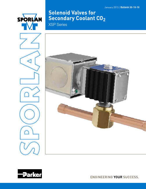
Parker Hannifin 芯片冷却液二级冷却系统CO2 XSP系列阀门用户指南说明书
D E B
A
Extended Connection 1.64” (42 mm)
Optional 1/2” (13 mm) Conduit Boss
Inches (mm)
VALVE SERIES
TYPE
A
B
C
D Fitting Depth
ODF
E Offset
XSP2S120
4.63” (118 mm)
January 2B0u1lle3ti/nB3u0l-l1e0t-in103–0-P1a0g-e101
Solenoid Valves for Secondary Coolant CO2
XSP Series
⚠WARNING – USER RESPONSIBILITY
Failure or improper selection or improper use of the products described herein or related items can cause death, personal injury and property damage.
When ordering complete valves, specify Valve Type, Connections, Voltage and Cycles. When ordering Body Assembly, specify Valve Type and Connections. When ordering Coil Assembly ONLY, specify Coil Type, Voltage and Cycles. Example: MKC-1 120/50-60.
This document and other information from Parker Hannifin Corporation, its subsidiaries and authorized distributors provide product or system options for further investigation by users having technical expertise.
APPDA04-41PWFA中文资料
Notes: 1. All dimensions are in millimeters (inches), Tolerance is ±0.25(0.01")unless otherwise noted. 2. Specifications are subject to change without notice.
Tape Specifications (Units : mm)
SPEC NO: DSAD1519 APPROVED : J. Lu
REV NO: V.1 CHECKED : Joe Lee
DATE: APR/11/2003 DRAWN: S.J.HOU
PAGE: 4 OF 4
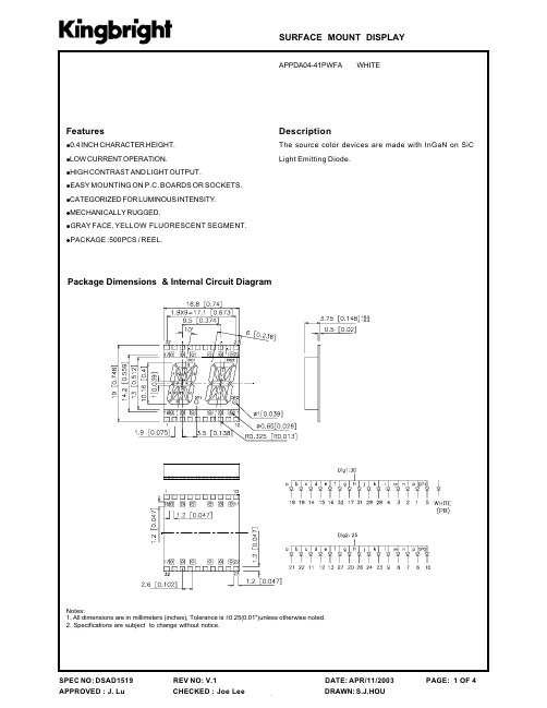
Description
The source color devices are made with InGaN on SiC Light Emitting Diode.
FLUORESCENT SEGMENT.
!PACKAGE :500PCS / REEL.
Package Dimensions & Internal Circuit Diagram
Electrical / Optical Characteristics at T)=25°C °
Sy m b o l VF IR X Chromaticity Coordinates Y C capacitance White White 0.34 65 pF VF=0V,f=1MHz Par am et er Forward Voltage Reverse Current White White 0.33 D ev i c e Ty p . 3.65 Max . 4.2 10 Un it s V uA Tes t Co n d it io n s I F =20mA V R = 5V
Parker Autoclave Engineers双阻流断阀门说明书

Parker Autoclave Engineers Double Block & Bleed valve is a two-stem ball valve with needle style vent valve providing economical and reliable isolation in critical areas superior in comparison to a standard, single valve. This valve is de-signed for use where critical isolation is needed to ensure that leakage does not occur. Our 3/8" and 5/8" Double Block & Bleed valves are designed to save space and weight while capable of pressures to 15,000 psi (1034 bar). These ball valves can also be modified to incorporate the use of special materials, optional seals with and capability for high tem-perature applications to 500°F (260°C).Double Block & Bleed Ball Valve Features:• One-piece, trunnion mounted style, stem design eliminates shear failure and reduces the effects of side loading found in two piece designs• Re-torqueable seat glands for longer seat life• Carbon filled PEEK seats offer excellent resistance to chemicals, heat, and wear/abrasion • Vee-Stem Needle Vent Valve with PTFE Packing • Full-port flow path minimizes pressure drop• Manufactured using UNS S31600 316 cold worked Stainless Steel• Low friction pressure assisted graphite filled PTFE stem seal increases cycle life and reduces operating torque • FKM o-rings for operation from 0° to 400°F (-18 to 204°C)Traceability is ensured by use of heat and purchase order codes etched on valve body that also includes model number, MAWP rating, and material type references. Parker Autoclave Engineers’ valves are complemented by a complete lineof Medium Pressure Cone & Thread, or NPT fittings, check valves, relief valves, and line filters.Ball ValveDouble Block & Bleed, 1/4 Turn3/8" & 5/8" Bore to 15,000 psi (1034 bar)6DB and 10DB Series6DB Series:.323" (8.20mm) Orifice - Pressures to 15,000 psi (1034 bar)Pressure Temperature RatingsTemperature ºF (ºC)PressurePSIG(Bar)100(38)200(93)300(150)400(204)500(260)(-18)5000(345)10000(690)15000(1034)1/2" LP ConnectionMP & NPT Connection6DB Series Ball Valve SeriesPressure Ratings are determined by the end connections chosen, see chart.Maximum Temperature rating is determined by the o-ring material.NPT connections are limited to 400°F max due to PTFE Sealant.** Special materials often have reduced MAWP ratings, see Technical brochure for assistance3Ball Valves: 6DB & 10DB Double Block and Bleed Series 02-1258SE 0821Ordering Guide:For complete information on available end connections and material options, see below. 6DB ball valves are furnished complete with tube or pipe connections. Standard valve has FKM o-rings [0-400ºF (204ºC) maximum].Basic Repair Kits:6DB Double Block & Bleed Valves are not repairable in field and must be returned to authorized repair center or factory location.4Ball Valves: 6DB & 10DB Double Block and Bleed Series 02-1258SE 08216DB Series 3/8" Bore Ball Valve Dimensions:Panel Mounting Dimensions:Material of Construction:* Centerline location of vent outlet port6DB Series 3/8" Bore Ball Valve Material:5Ball Valves: 6DB & 10DB Double Block and Bleed Series 02-1258SE 082110DB Series:.623" (15.82mm) Orifice- Pressures to 15,000 psi (1034 bar)Pressure Temperature RatingsTemperature ºF (ºC)PressurePSIG(Bar)100(38)200(93)300(150)400(204)500(260)(-18)5000(345)10000(690)15000(1034)NPT ConnectionSF Connection10DB Series Ball Valve SeriesPressure Ratings are determined by the end connections chosen, see chart.Maximum Temperature rating is determined by the o-ring material.NPT connections are limited to 400°F max due to PTFE Sealant.** Special materials often have reduced MAWP ratings, see Technical brochure for assistance Series M10DB Vent Valve Option Shown7Ball Valves: 6DB & 10DB Double Block and Bleed Series 02-1258SE 0821Ordering Guide:For complete information on available end connections and material options, see below. 10DB Series ball valves are furnished complete with tube or pipe connections. Standard valve has FKM o-rings [0-400ºF (204ºC) maximum].Basic Repair Kits:10DB Double Block & Bleed Valves are not repairable in field and must be returned to authorized repair cen-ter or factory location.810DB Series 5/8" Bore Ball Valve Dimensions:Panel Mounting Dimensions:Material of Construction:* Centerline location of vent outlet port10DB Series 5/8" Bore Ball Valve Material:9 Ball Valves: 6DB & 10DB Double Block and Bleed Series 02-1258SE 082110Ball Valves: 6DB & 10DB Double Block and Bleed Series 02-1258SE 0821NOTES:High PressureValves • Fittings • Tubingto 150,000 psi.Reactors • Vessels InstrumentationAir Driven, High Flow, High Pressure Liquid PumpsParker’s Motion & Control TechnologiesAt Parker, we’re guided by a relentless drive to help our customers become more productive and achieve higher levels of profitability by engineeringthe best systems for their requirements. It means looking at customer applications from many angles to find new ways to create value. Whateverthe motion and control technology need, Parker has the experience, breadth of product and global reach to consistently deliver. No company knows more about motion and control technology than Parker. For further information call 1-800-C-Parker.11Ball Valves: 6DB & 10DB Double Block and Bleed Series 02-1258SE 0821Ball Valves: 6DB & 10DB Double Block and Bleed Series 02-1258SE 0821! CAUTION !Do not mix or interchange component parts or tubing with those of other manufacturers. Doing so is unsafe and will void warranty.Parker Autoclave Engineers Valves, Fittings, and Tools are not designed to interface with common commercial instrument tubing and are designed to only connect with tubing manufactured toParker Autoclave Engineers AES specifications. Failure to do so is unsafe and will void warranty.Offer of SaleThe items described in this document are available for sale by Parker Hannifin Corporation, its subsidiaries or its authorized distributors. Any sale contract entered by Parker will begoverned by the provisions stated in Parker's standard terms and conditions of sale (copy available upon request).©2021 Parker Hannifin Corporation | Autoclave Engineers is a registered trademark of the Parker Hannifin Corporation Literature #: 02-1258SE August 2021Parker WorldwideISO-9001 CertifiedInstrumentation Products Division Autoclave Engineers Operation 8325 Hessinger Drive Erie, PA 16509-4679Tel: 814 860 5700Fax: 814 860 /ipdInstrumentation Products Division Division Headquarters 1005 A Cleaner WayHuntsville, AL 35805 USA Tel: 256 881 2040Fax: 256 881 5072WARNINGFAILURE, IMPROPER SELECTION OR IMPROPER USE OF THE PRODUCTS AND/OR SYSTEMS DESCRIBED HEREIN OR RELATED ITEMS CAN CAUSE DEATH,PERSONAL INJURY AND PROPERTY DAMAGE.This document and other information from Parker Hannifin Corporation, its subsidiaries and authorized distributors provide product and/or system options for further investigation by users having technical expertise. It is important that you analyze all aspects of your application and review the information concerning the product or system in the current product catalog. Due to the variety of operating conditions and applications for these products or systems, the user, through its own analysis and testing, is solely responsible for making the final selection of the products and systems and assuring that all performance, safety and warning requirements of the application are met. The prod-ucts described herein, including without limitation, product features, specifications, designs, availability and pricing, are subject to change by Parker Hannifin Corporation and its subsidiaries at any time without notice.North AmericaUSA – Corporate, Cleveland, OH Tel: +1 256 896 3000USA – IPD, Huntsville, AL Tel: +1 256 881 2040*****************USA – IPD, (Autoclave), Erie, PA Tel: +1 814 860 5700*******************CA – Canada, Grimsby, Ontario Tel +1 905-945-2274*********************South AmericaAR – Argentina, Buenos Aires Tel: +54 3327 44 4129 ******************BR – Brazil, Diadema, SP Diadema, SPTel: +55 11 4360 6700******************CL – Chile, Santiago Tel: +56 (0) 2 2303 9640******************MX – Mexico, Toluca Tel: +52 722 275 4200*******************Asia PacificAU – Australia, Dandenong Tel: +61 (0)2 9842 5150******************************CN – China, Shanghai Tel: +86 21 2899 5000*****************************HK – Hong Kong Tel: +852 2428 8008IN – India, MumbaiTel: +91 22 6513 7081-85ID – Indonesia, Tangerang Tel: +62 2977 7900********************JP – Japan, Tokyo Tel: +(81) 3 6365 4020******************KR – South Korea, Seoul Tel: +82 2 559 0400*******************MY – Malaysia, Selangor Tel: +603 784 90 800*******************SG – Singapore,Tel: +65 6887 6300*******************TH – Thailand, Bangkok Tel: +66 2 186 7000*********************TW – Taiwan, Taipei Tel: +886 2 2298 8987*************************VN – Vietnam, Hochi Minh City Tel: +848 382 508 56**********************Europe, Middle East, AfricaAE – UAE, Dubai Tel: +971 4 812 7100********************AT – Austria, Wiener Neustadt Tel: +43 (0)2622 23501-0*************************AT – Eastern Europe, Wiener Neustadt Tel: +43 (0)2622 23501 900****************************AZ – Azerbaijan, Baku Tel: +994 50 2233 458****************************BE/LU – Belgium, Nivelles Tel: +32 (0)67 280 900*************************BG – Bulgaria, Sofia Tel: +359 2 980 1344**************************BY – Belarus, Minsk Tel: +48 (0)22 573 24 00*************************CH – Switzerland, Etoy Tel: +41 (0) 21 821 87 00*****************************CZ – Czech Republic, Klecany Tel: +420 284 083 111*******************************DE – Germany, Kaarst Tel: +49 (0)2131 4016 0*************************DK – Denmark, Ballerup Tel: +45 43 56 04 00*************************ES – Spain, Madrid Tel: +34 902 33 00 01***********************FI – Finland, VantaaTel: +358 (0)20 753 2500*************************FR – France, Contamine s/Arve Tel: +33 (0)4 50 25 80 25************************GR – Greece, Athens Tel: +30 210 933 6450************************HU – Hungary, Budapest Tel: +36 223 885 470*************************IE – Ireland, DublinTel: +353 (0)1 466 6370*************************IT – Italy, Corsico (Ml)Tel: +39 02 45 19 21***********************KZ – Kazakhstan, Almaty Tel: +7 7273 561 000****************************NL – The Netherlands, Oldenzaal Tel: +31 (0)541 585 000********************NO – Norway, Stavanger Tel: +47 66 75 34 00************************PL – Poland, Warsaw Tel: +48 (0)22 573 24 00************************PT – Portugal, Leca da Palmeira Tel: +351 22 999 7360**************************RO – Romania, Bucharest Tel: +40 21 252 1382*************************RU – Russia, Moscow Tel: +7 495 645-2156************************SE – Sweden, Spånga Tel: +46 (0)8 59 79 50 00************************SK – Slovakia, Banská Bystrica Tel: +421 484 162 252**************************SL – Slovenia, Novo Mesto Tel: +386 7 337 6650**************************TR – Turkey, Istanbul Tel: +90 216 4997081************************UA – Ukraine, KievTel: +48 (0)22 573 24 00*************************UK – United Kingdom, Warwick Tel: +44 (0)1926 317 878********************ZA – South Africa, Kempton Park Tel: +27 (0)11 961 0700*****************************。
Parker CO Series 单向阀门目录说明书

Check Valves (CO Series)Catalog 4130-CORevised, October 1999IntroductionParker CO Series Check Valves are designed for uni-directional flow control of fluids and gases in industries such as chemical processing, oil and gas production and transmission, pharmaceutical, pulp and paper, power and utilities. The CO Series Check Valve is particularly suitable for applications requiring high integrity leak rates and re-sealing capabilities.Materials of ConstructionModel Shown: 4V-CO4L-5-V-SS2Features•Seal integrity across the seat and to atmosphere is tested to 4 x 10⁻⁹ std atm-cc/sec (4 x 10⁻¹⁰ kPa – L/sec) for the CO4L with fluorocarbon rubber seals. All other sizes and seal materials are tested to 1 x 10⁻⁵ std atm-cc/sec (1 x 10⁻⁶ kPa – L/sec).•Special seat seal design provides a repeatable high integrity seal and accurate cracking pressures •100% factory tested. Cracking pressures include:1/3, 1, 5, 10, 25, 50, 75, and 100 psi.•Valves are available with Male and Female NPT, CPI TM ,A-LOK ®, UltraSeal, Male and Female VacuSeal, and Tube Adapter•Heat code traceability•Color coded identification labels indicate seal materialSpecifications•Pressure Rating:6000 psig CWP (414 bar)•Temperature Rating:Fluorocarbon Rubber-10 °F to 400 °F (-23 °C to 204 °C)Buna-N Rubber-30 °F to 250 °F (-34 °C to 121 °C)Ethylene Propylene Rubber-70 °F to 275 °F (-57 °C to 135 °C)Highly Fluorinated Fluorocarbon Rubber-20 °F to 200 °F (-29 °C to 93 °C)•Orifice: .156" to .406" (4.0mm to 10.3mm)•Cv Factor: .43 to 2.65Flow Calculations with 1000 psig (69 bar) Inlet PressureParker Hannifin CorporationInstrumentation Valve Division Jacksonville, AlabamaA479, TYPE 316L.2Optional seal materials are available. See How to Order section.Lubrication: Perfluorinated Polyether3Label Color Cross ReferenceTesting: All valves are 100% tested for crack, re-seal, and D = Hex of nuts where applicable Model Shown: 4V-CO4L-5-KZ-SSParker Hannifin Corporation Instrumentation Valve Division Jacksonville, Alabama‡Tested in accordance with ISA S75.02. Gas flow will be choked when P 1 - P 2 I P 1 = x T.WARNINGFAILURE, IMPROPER SELECTION OR IMPROPER USE OF THE PRODUCTS AND/OR SYSTEMS DESCRIBED HEREIN OR RELATED ITEMS CAN CAUSE DEATH, PERSONAL INJURY AND PROPERTY DAMAGE.This document and other information from Parker Hannifin Corporation, its subsidiaries and authorized distributors provide product and/or system options for further investigation by users having technical expertise. It is important that you analyze all aspects of your application and review the information concerning the product or system in the current product catalog. Due to the variety of operating conditions and applications for these products or systems, the user, through its own analysis and testing, is solely responsible for making thefinal selection of the products and systems and assuring that all performance, safety and warning requirements of the application are met.The products described herein, including without limitation, product features, specifications, designs, availability and pricing, are subject to change by Parker Hannifin Corporation and its subsidiaries at any time without notice.How To OrderThe correct part number is easily derived by following the circled number sequence.The six product characteristics required are coded as shown below. *Note: If both the inlet and outlet ports are the same, eliminate the outlet port designator.Example :----Port PortSizePressure Material MaterialDescribes a CO Series Check Valve with 1/4" male NPT inlet and a 1/4" female NPT outlet, 1 psig cracking pressure,4Offer of SaleThe items described in this document are hereby offered for sale by Parker Hannifin Corporation, its subsidiaries or its authorized distributors. This offer and its acceptance are governed by the provisions stated in the “Offer of Sale” located in Catalog 4103 Instrumentation Valve Technical Guide.© Copyright 1999, Parker Hannifin Corporation. All Rights Reserved.A -Two ferrule A-LOK ®compression portAvailable End ConnectionsF -ANSI/ASME B1.20.1Internal pipe threadsM -ANSI/ASME B1.20.1External pipe threadsZ -Single ferrule CPI TM compression portV -VacuSeal face seal port Q -UltraSeal face seal portV1-Internal VacuSeal face seal portCO Series Check ValvesParker Hannifin Corporation Instrumentation Valve Division Jacksonville, AlabamaTA -Tube adapter connectionOptionsOxygen Cleaning - Add the suffix -C3 to the end of the part number to receive valves cleaned and assembled for oxygen service in accordance with Parker specification ES8003. Example: 4A-CO4L-1-BN-SS-C3Special Cleaning - All face seal ended valves are cleaned in accordance with Parker Specification ES8001. This is an option for all valves by adding the suffix -C1 to the end of the part number. Example: M6A-CO4L-10-SS-C1Material - Contact the factory for availability of AOD/VAR stainless steel and ID Electropolish.5Note: To determine MPa, multiply bar by 0.1CO Series Check ValvesParker Hannifin Corporation Instrumentation Valve Division Jacksonville, AlabamaBCP means “Below Cracking Pressure”Cracking pressure is defined as the upstream pressure at which a detectable flow is measured.Re-seal pressure is defined as the upstream pressure at which the check valve closes bubble-tight.Example: For a valve with a spring having a rated crackingpressure of 25 psig, (1.72 bar) the actual cracking pressure ranges between 20 and 30 psig (1.38 and 2.07 bar). The re-seal pressure range would be 16 to 20 psig (1.10 to 1.38 bar).Check valves having springs with rated crack pressures of 3psig (0.21 bar) or less may require up to 4 psig (0.28 bar) back pressure to re-seal bubble-tight.Note: Check valves which are not actuated for a period of time may initially crack at higher than the above crack pressure ranges.Parker Hannifin CorporationInstrumentation Valve Division2651 Alabama Highway 21 NorthJacksonville, AL 36265-9681Phone: (256) 435-2130Fax: (256) 435-7718/IVDCatalog 4130-CO, 20M, 10/99。
武汉保尔富产品手册
目录1.罐下采样器 (1)2.浮动出油装置 (6)3.油罐自动切水器 (9)4.油罐油品随位调合旋转喷头 (15)5.密闭取样器系列 (18)6.管道采样器系列 (44)1.罐下采样器1.1.引言为了解决储罐内液体采样繁琐的问题,我公司根据国家标准GB/T4756-1998《石油液体手工取样法》检验的规定,结合多年采样器的生产实践经验研制出的PTBS型系列罐下采样器产品,深受用户好评。
1.2.产品优势1)所采取的油样准确性高;2)采用柔性连接技术,从而减少了罐内液体扰动对浮臂的冲击力量,延长了罐内装置的使用寿命。
3)操作简单、方便:采样工不需上罐,这样既减轻了采样工人的劳动强度又保证了安全,特别是在气候恶劣条件下,更能显示其优越性。
4)自动化程度高,节省采样时间,提高工作效率。
5)操作箱一体化设计,便于用户操作、安装、维修。
6)取样无残留,取样嘴无滴漏。
7)苯等有毒介质罐均为密闭耐压玻璃瓶取样,确保采样工的健康,无安全之忧。
1.3.产品型号1)PTBS-K型:用于内浮顶罐、外浮顶罐2)PTBS-X型:用于拱顶罐、内浮顶罐、外浮顶罐;3)PTBS-H型:用于无搅拌设备的拱顶罐、内浮顶罐、外浮顶罐;4)PTBS-I型:专门用于无搅拌设备的矮型拱顶罐5)PTBS-G型:专门用于有搅拌设备的拱顶罐及内浮顶罐,在满罐条件下取顶部、上部、中部、下部、底部、出口样。
1.4.产品结构图1.5.工作原理采样器装置所采用的结构形式能完全准确无误地保证采样法和取样位置规定的要求。
采样器装置是将三根(上、中、下)采样管固定在支撑管上,一根采上部油样,一根采中部油样,另一根采下部油样,支撑杆上端连浮标,下端固定在支座上。
当液面升降时,浮标随之浮动,采样管亦随之升降,因此三根采样管的开口高度始终保持在规定的采样位置。
1.6.适用范围适用介质范围:石脑油、汽油、煤油、柴油、原油、蜡油、沥青、化工原料等采用形式:相对点、定点采样、相对点或定点的混和液均质采样。
Parker Hannifin 卡克尔汽缸泵系列F1和VP1产品介绍说明书
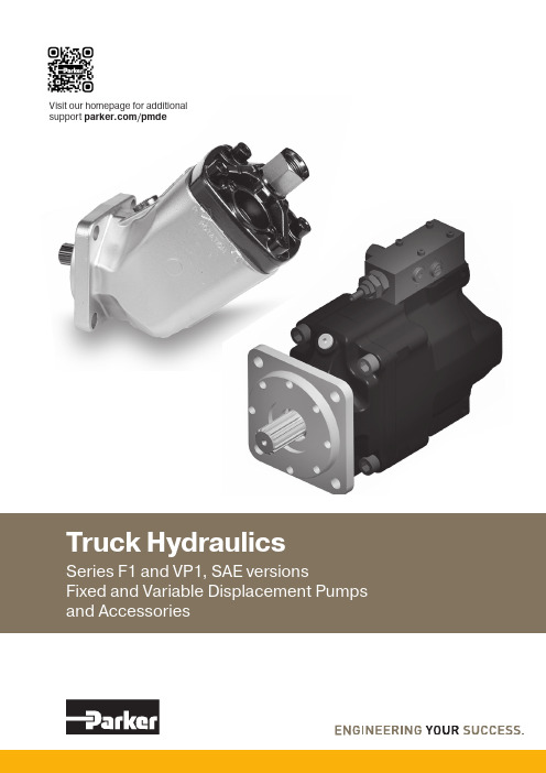
Visit our homepage for additional support/pmdeConversion factors1 kg ...............................................................2.20 lb 1 N ..............................................................0.225 lbf 1 Nm .........................................................0.738 lbf ft 1 bar .............................................................14.5 psi 1 l .....................................................0.264 US gallon 1 cm3.......................................................0.061 cu in 1 mm ...........................................................0.039 in9/ 5 °C + 32 ............................................................1°F1 kW ..............................................................1.34 hpContent PageF1 PumpFixed Displacement – Axial Piston Pump, SAE version ..............................................................................4 – 7 VP1 PumpVariable Displacement – Axial Piston Pump. SAE version .........................................................................8 – 14 Pump and line selection .....................................................................................................................15 – 17 Suction fittings and fitting kits . (18)Installation and start up, F1 and VP1 ....................................................................................................19 – 21F1 PumpF1-SAEContents ...........................................................................................Page General Information .. (5)F1 Pump SAE (5)Specifications (6)Pump cross section (6)Installation Dimensions, F1-25, -41, -51 and -61 (SAE) (7)Ordering code (SAE) (7)Port size (7)Standard SAE versions (7)Pump and Line selection (15)Suction fittings (18)Installation and start up (19)Piston_lockingLeif A./990806F1 piston with laminated piston ring.F1 piston-to-shaft locking.Series F1 is a further development of our well known 'truck pump', the F1. The F1 offers many additional val-ues for operators of cargo cranes, hook loaders, skip loaders, forest cranes, concrete mixers and similar truck applications.Series F1 is a very efficient and straight forward pump design with unsurpassed reliability.Its small envelope size gives a simple and inexpensive installation.Features:• Laminated piston rings – low leakage • Positive synchronisation with timing gear • Operating pressure up to 350 bar (5076 psi)• Installation above the reservoir level possible • Tolerates low temperatures and high temperature shocks • Shaft end and mounting flange meet the standard SAE-B• 4 sizes -25 / -41 / -51 / -61 cm 3/rev 1.56 / 2.50 / 3.12 / 3.63 cu in/rev ... thanks to:- 45° bent-axis angle- Optimal inlet port geometry in the end cap - Single housing design- Spherical pistons – high speeds - Laminated piston rings – low leakage - Positive synchronisation with timing gear - Installation above the reservoir level possible - Tolerates low temperatures and high temperature shocks - Shaft end and mounting flange meet the SAE standard for all sizesF1 Pump SAEF1_61_SAE_cross_ny.eps 1. Input shaft 2. Bearings 3. Shaft seal 4. Housing 5. Timing gear 6. Barrel support 7. Piston withpiston ring 8. Cylinder barrel9. End capNOTE: For noise level information, contact Parker Hannifin.Specifications1) Theoretical values2) Valid at an inlet pressure of 1.0 bar/15 psi (abs.) when operating on mineral oil at a viscosity of 30 mm 2/s (cSt)/150 SUS.F1_SAE_ny5.eps Leif A./06-08-078Installation dimensions, F1-25, -41, -51 and -61 (SAE)Dimensions in mm [inches]The suction 1/16"-12 UN(x4)16]SAE J498b, class 1.Ordering code (SAE)Example: F1- 61 - R U - S V - SF1 size25, 41, 51 or 61 Shaft rotation R Right hand L Left handMain port U SAE O-ring, UN threadsShaft end S SAE spline "B" splineShaft seal V FPM Mounting flangeS SAE "B"1) BSP-to-SAE adapter(included)Standard SAE versions Port sizeVP1 PumpContents ...........................................................................................Page General Information . (9)Specifications (10)VP1-095/-110/-130 cross section (10)LS control (for VP1-095/-110/-130) (11)Installation Dimensions (for VP1-095/-110/-130) (12)Ordering information (13)VP1 in load sensing systems (13)Systems comparison (13)Standard model numbers (13)LS load sensing control function (14)LS control adjustments (14)Hydraulic schematic for VP1-095/-110/-130 (14)Pump and Line selection (15)Suction fittings (18)Installation and start up (19)VP1 Pump SAEDesignLarge angle – compact designThe pump design permits a large angle, 20°, betweenpiston and slipper shoe/swashplate, providing compact-ness and small outer dimensions.Long life The VP1 is designed for trucks with hydraulic load sensing systems. It is sturdy, yet simple, with few moving parts. The result is a reliable pump with long service life.The VP1 is a variable displacement pump for truck applications. It can be close-coupled to a gearbox PTO (power take-off) or to a coupling independent PTO (e.g. an engine PTO).An application that makes full use of all the features of the VP1 is truck cranes with a load sensing system. The complex systems of refuse collection vehicles and sew-age trucks as well as various combinations of tippers, cranes, snow ploughs, and salt/sand spreaders can also be greatly simplified and optimised with the VP1 pump.The VP1 provides the hydraulic system with the correct amount of fluid at precisely the right moment, effectively reducing energy consumption and heat generation. This means a smoother and quieter hydraulic system with much reduced impact on the environment.The VP1 is highly efficient and extremely light. It is reliable, economical and easy to install.The 3 sizes, VP1-095, -110 and -130 have small installa-tion dimensions.The VP1 is suitable for all load sensing systems, regardless of make.Features• Variable displacement• Low noise level• High power-to-weight ratio • Compact and light• Highly efficient • Sturdy design• Withstands low temperatures Retainer plateThe retainer plate (refer to the cut-away illustration in next page) is of a heavy duty design which makes the pump withstand high shaft speeds and fast speed changes.(e.g. engine PTO).Specifications1) M ax 6 seconds in any one minute.2)A t an inlet pressure of 1.0 bar (abs.) with mineral oil at a viscosity of 30 mm 2/s (cSt).VP1-095/-110/-130 cross section1. Shaft seal2. Roller bearing3.‘Upper’ purge plug 4. Bearing shell 5. Setting screw(pressure relief valve) 6. Setting bushing (standby pressure) 7. Control8. Piston with piston shoe 9. ‘Upper’ setting piston (control pressure) 10. Needle bearing 11. Shaft12. Drain hole, shaft seals 13. ‘Lower’ purge plug 14. Bearing housing 15. Swash plate 16. Retainer plate17. ‘Lower’ setting piston (pump pressure) 18. Cylinder barrel 19. Valve plate 20. Barrel housing21. SAE C 4 bolt flangeLS control (for VP1-095/-110/-130)3. B asic valve setting (factory set) DO NOT TOUCH!LS control cross section.To be connected 1. S ignal pressure cut-off 2. Counter nut, 4. S tandby pressure setting, factory set at 25 bar (362.6 psi);(1 turn = 17 bar) (1 turn = 246.6 psi)bushing 4LS control ports.VP1-095/-110/-130Dimensions in mm [inches]View A–ALeft hand rotating pumpView A–ARight hand rotating pumpVP1 in load sensing systemsWhen installed in a load sensing system, the VP1 supplies the correct amount of flow required by the various work functions currently engaged.This means that energy consumption and heat generation are minimised and much reduced in comparison with a fixed displacement pump used in the same system. Diagram 1 shows the required power (flow times pres-sure) in a constant flow system with a fixed displacement pump.Diagram 2 shows the sharply reduced power requirement in a load sensing system with a variable displacement pump such as the VP1.In both cases the pump pressure is slightly higher than what is required by the heaviest load (’Load 2’) but the VP1, because of the much smaller flow being delivered, needs only the power indicated by the shaded area ’Load power’. In a constant flow system, on the other hand, excess fluid is shunted to tank and the corresponding power, ’Wasted power’ (shown in diagram 1), is a heat loss.Pressure Corner powerp Max p Load Q Load 1-3Q MaxFlowWasted powerLoad power L o a d 1L o a d 2L o a d 3PressureCorner powerp Maxp LoadQ Load 1-3Q MaxFlowWasted powerLoad powerL o a d 1L o a d 2L o a d 3Diagram 1. Constant flow system with a fixed displacement pump.Diagram 2. Constant flow system with a variabledisplacement pump (e.g. VP1).Consequently, the desired direc-tion of rotation must be stated when ordering .S SAE C 4 bolt* Simultaneous operation of loads with non-equal flows and pressures; refer to the above diagrams.Systems comparisonLS load sensing control functionRefer to corresponding hydraulic schematic below.A selected 'opening' of the directional control valve spool corresponds to a certain flow to the work function. This flow, in turn, creates a pressure differential over the spool and, consequently, also a ∆p between the pump outlet and the LS port.When the differential pressure decreases (e.g. the direc-tional valve is ‘opened’ further) the ∆p also decreases and the LS valve spool moves to the left. The pressure to the setting pistons then decreases and the pump displace-ment increases.The increase in pump displacement stops when the ∆p finally reaches the setting (e.g. 25 bar) and the forces acting on the valve spool are equal.If there is no LS signal pressure (e.g. when the directional valve is in the neutral, no-flow position) the pump only delivers sufficient flow to maintain the standby pressure as determined by the ∆p setting.Hydraulic schematic for VP1-095/-110/-130To work function1. D irectional, load sensing control valve2. Load signal orifice (1.0 mm)3. Gauge port4. S ignal pressure limiter adjustment5. Standby (∆p) pressure adjustment6. S ystem pressure dampening orifice (fixed)7. B leed-off nozzle (1.2 mm)LS control adjustments Pressure limiter* Note : Max allowed pressure for size VP1-130 is 370 bar LS load sensing valveThe factory setting, and the standard orifice sizes shown in the corresponding schematic below, will usually pro-vide an acceptable directional valve characteristic as well as system stability.For additional information, contact Parker Hannifin.Flow and torque formulas(no regard to efficiency)Flow: Q = [l/min]where: D is pump displacement [cm 3/rev] n is shaft speed [rpm] Torque: M = [Nm]where: D is pump displacement [cm 3/rev] p is utilised pressure [bar]D x p63D x n 1000Pump selection F1The following table shows pump flow at selected PTO gear ratios and engine rpm's.NOTE:- Make sure max torque and bending moment (due to the weight of the pump) of the utilised PTO are not exceeded. (The approx. center of gravity of the various pump sizes are shown in the installation drawings).- Make sure max allowed output torque from the PTO is not exceeded.- Contact Parker Hannifin if the inlet (suction) pressure is believed to be less than 1.0 bar (absolute);insufficient inlet pressure can cause noise and pump damage because of cavitation.Line selection all pumpsA suitable pump size for a truck application can be se-lected as follows:Operating conditionsAs an example, a cargo crane specifies: •Flow: 60 – 80 l/min (15.84 – 21.12 gpm) Pressure: 230 bar (3336 psi) Diesel engine speed ≈ 800 rpmDetermine pump speedAs example a PTO with a Gear Ratio of 1:1.54. The pump speed will be: • 800 x 1.54 ≈ 1200 rpmSelect a suitable pump sizeUse diagram 1 and select a pump that will provide 60 – 80 l/min at 1200 rpm.Follow line 'a' (1200 rpm) until it crosses line 'b' (70 l/min).• F1-61 is a suitable choiceRequired input torqueMake sure the PTO and the gear-boxt olerates the pump torque. Use diagram 2 to obtain the required pump torque.Follow a line from 'c' (230 bar) until it c rosses the F1-61 line (the selected pump).• Read 220 Nm (at 'd')NOTE: A rule-of-thumb is to select theh ighest PTO ratio and the smallest pump size that meets the crane specification with-out exceeding the pump speed, p ressure, and power limitations.Diagram 2.Diagram 1.Inlet (suction)line‘b’ Flow [l/min]Flow [gpm]Pump speed [rpm]Torque [Nm] / [lbf • f]Pressure [bar] &[psi]1450290143515802Table 1. Outlet (pressure) lineIn order to obtain sufficient inlet (suction) pressure to the pump, low noise level and low heat generation, flow speeds shown in table 2, right, should not be exceeded. From table 1 (page 13), select the smallest line d imension that meets the flow speed recommendation; example: • At 100 l/min 26.42 gpm , a 50 mm 2" suction line and a 25 mm 1" pressure line is needed.NOTE: Long inlet (suction) lines, low inlet pressure (caused by e.g. a reservoir positioned below the pump) and/or low temperatures may require larger line d imensions.Alternatively, the pump speed will have to be lowered to avoid pump cavitation (which may cause noise, deterio-rating performance and pump damage). Example 1 Pressure line Q = 65 l/min 17.17 gpm d = 3/4"v = 3.8 m/s 12.47 feet/s Example 2Suction line Q = 50 l/min 13.21 gpm v = 0.8 m/s 2.62 foot/s d = 1 1/2"NomogramFlow – Line dimension – Flow velocitydiametre [Ø mm]Table 3.1gpm=3.785 l/min 1 l/min=0.264 gpm 1 foot/s=0.305 m/s 1 m/s=3.281 feet/s 1psi=0.0689 bar 1 bar=14.504 psiTable 2.Truck HydraulicsCatalogue MSG30-8220/UK Suction fittings for series F1, VP1-095, -110 and -130’Straight’ suction fittings for F1, VP1-095/-110/-13045° suction fittings for F1, VP1-095/-110/-13090° suction fittings for F1, VP1-095/-110/-130145° suction fitting for F1, VP1-095/-110/-13090° fitting145° fittingA ’suction fitting’ consists of a straight, 45°, 90° or 135°suction fitting, clamps, cap screws and O-ring.Spare partsAdditional Hold-down-clamp kit consists of: hold-down-clamp cap screw and O-ring Ordering no. 378 1321Additional Hold-down-clamp kit for mounting on BPV Ordering no. 378 24391) Recommended for size F1-25.2) Recommended for size F1-41,-51,-61. 3)(3 clamps and 3 screws)Installation Dimensions FittingsLeif A./05-03-08F1plus_e.eps Leif A./05-03-29Leif A./05-03-29Installation and start-up for F1Drain lineFixed displacement pumps don’t need an external drain line as they are internally drained.When the pump is mounted in a Engine-PTO we recommend a drain line from the bypass valve directly to oil tank.FiltrationFiltration should follow ISO standard 4406, code 20/18/13.To obtain the longest life of fixed dis-placement pumps, we recommend an oil cleanliness of 10 µm (absolute).Start-upMake sure the entire hydraulic system is clean before filling it with a recommended hydraulic fluid.In particular, make sure the pump is filled (to at least 50 %) as the internal leakage does not provide sufficient lubrication at start-up.FluidsThe fixed displacement pumps data shown in the specifications for each pump in chapter 1 and 2 are valid when operating on high quality, min-eral based hydraulic oil.Type HLP (according to DIN 51524) hydraulic oil is suitable as well as biologically degradeable fluids like natural and synthetic esters and polyalfaolefins.The utilised hydraulic fluid shall meet one of the following Swedish standards:- SS 15 54 34- SMR Hydraulic Oil Standard 1996-2.Contact Parker Hannifin for further information. NOTE:- ATF (automatic transmission fluid) and API type CD engine oils mayalso be useable.- Seals are made of nitrile rubber;make sure the utilised fluid is com-patible with this material.Fluid temperatureMain circuit: Max 75 °C, 167 °F .Direction of rotationThe pictures above show direction of flow vs. shaft rotation.The direction of rotation can be changed (i.e. from right hand to left hand) by turning the end cap.Remove the four cap screws and turn the end cap about half a turn while making sure it stays in contact with the barrel housing.Re-fit the cap screws and torque to 59 – 74 lbf ft (80 – 100 Nm).InstallationMake sure max torque and bending moment (due to the weight of the pump) of the utilised PTO are not exceeded. (The approx. center of gravity of the various pump sizes areshown in the installation drawings). NOTE:In order to obtain the longest bearinglife, the pump should be installed ac-cording to the information shown onpage 20 "Pump bearing life".Fluid viscosityRecommended viscosity:20 to 30 mm 2/s (cSt).Operating viscosity limits:- Min 10 mm 2/s; max 400 mm 2/s.- At start-up, max 4000 mm 2/s.clockwise) rotating pump.clockwise) rotating pump.Before start-up, the housing mustbe filled with hydraulic fluid.Pump_positions_GB.eps Leif A./020115Pump_positions_GB.eps Leif A./020115Pump_positions_GB.eps Leif A./020115Fig. 1.Fig. 2.Fig. 3.Truck HydraulicsCatalogue MSG30-8220/UKFig. 8. VP1 should be installed below the reservoir fluid level.Purging should be performed when the pump is connected to the reservoir and the system is filled with fluid.Fluid temperatureMain circuit: Max 75 °C 167 °F .ViscosityRecommended viscosity: 20 to 30 mm 2/s (cSt).Operating viscosity limits: 10 to 400 mm 2/s.At start-up:Max 1000 mm 2/s.FiltrationTo obtain long VP1 life, we recommend a filtration level of:• 25 µm (absolute) in clean environment or at low pressures.• 10 µm (absolute) in contaminated environment or at high pressures.Filtration should meet ISO standard 4406: code 20/18/13.Drain lineThe LS valve requires a separate drain line; it should be routed directly to the reservoir (refer to fig. 8).Start-upMake sure the entire hydraulic system is clean before filling it with a recommended fluid.In addition, the VP1 pump must be purged to remove any entrapped air in the pump housing; utilise the uppermost purge port (fig. 8).Before start-up, open the plug, purge the pump,Direction of rotationThe basic VP1 pump is uni-directional; there is a left hand and a right hand version (indicated by the arrow on the side of the VP1 pump (fig. 4 and 5).Consequently, the required direction of rotation must be stated when ordering the pump.InstallationThe VP1 can be installed (close-coupled) directly on a PTO.Before start-up, the pump must be filled with hydraulic fluid and purged. Utilise the uppermost purge plug (refer to the installation drawing on page 12, c hapter 2).Figure 6 (page 19) shows two ways of installing a gear on the VP1 shaft. On a non-geared or a geared PTO with support bearings, the pump shaft is usually installed directly in the internally splined PTO output shaft.Make sure max torque and bending moment (due to the weight of the pump) of the utilised PTO are not exceeded. (The approx. center of gravity of the various pump sizes are shown in the installation drawings).Hydraulic fluidsThe VP1 data shown in the specifications onpage 10 are valid when operating on a high quality, min-eral based fluid.Hydraulic fluids type HLP (DIN 51524), ATF (automatic transmission fluids), and API type CD engine oils are suitable.Fig. 4. Left hand rotating pump.Fig. 5. Right hand rotating pump.Installation and start-up for VP1Installation and start upVP1 SAEOffer of SalePlease contact your Parker representation for a detailed ”Offer of Sale”.Parker Hannifin Ltd. Tachbrook Park Drive Tachbrook Park, Warwick, CV34 6TU United Kingdom Catalogue MSG30-8220/UK 01/2022© 2022 Parker Hannifin Corporation. All rights reserved.European Product Information Centre Free phone: 00 800 27 27 5374(from AT, BE, CH, CZ, DE, DK, EE, ES, FI, FR, IE, IL, IS, IT, LU, MT, NL, NO, PL, PT, RU, SE, SK, UK, ZA)Europe, Middle East, AfricaAE – United Arab Emirates, DubaiTel: +971 4 8127100BE/NL/LU – Benelux, Hendrik Ido AmbachtTel: +31 (0)541 585 000BY – Belarus, MinskTel: +48 (0)22 573 24 00CH – Switzerland, EtoyTel: +41 (0)21 821 87 00CZ – Czech Republic, PragueTel: +420 284 083 111DE – Germany, KaarstTel: +49 (0)2131 4016 0DK – Denmark, Ballerup Tel: +45 43 56 04 00ES – Spain, MadridTel: +34 902 330 001FI – Finland, VantaaTel: +358 (0)20 753 2500FR – France, Contamine s/Arve Tel: +33 (0)4 50 25 80 25HU – Hungary, BudaörsTel: +36 23 885 470IE – Ireland, DublinTel: +353 (0)1 466 6370IL – IsraelTel: +39 02 45 19 21IT – Italy, Corsico (MI)Tel: +39 02 45 19 21NO – Norway, AskerTel: +47 66 75 34 00PL – Poland, WarsawTel: +48 (0)22 573 24 00PT – PortugalTel: +351 22 999 7360RO – Romania, Bucharest Tel: +40 21 252 1382RU – Russia, MoscowTel: +7 495 645-2156SE – Sweden, BoråsTel: +46 (0)8 59 79 50 00SL – Slovenia, Novo Mesto Tel: +386 7 337 6650TR – Turkey, IstanbulTel: +90 216 4997081UK – United Kingdom, Warwick Tel: +44 (0)1926 317 878ZA – South Africa,Kempton ParkTel: +27 (0)11 961 0700North AmericaCA – Canada, Milton, Ontario Tel: +1 905 693 3000US – USA, ClevelandTel: +1 216 896 3000Asia PacificAU – Australia, Castle Hill Tel: +61 (0)2-9634 7777CN – China, ShanghaiTel: +86 21 2899 5000HK – Hong KongTel: +852 2428 8008IN – India, MumbaiTel: +91 22 6513 7081-85JP – Japan, TokyoTel: +81 (0)3 6408 3901KR – South Korea, Seoul Tel: +82 2 559 0400MY – Malaysia, Shah Alam Tel: +60 3 7849 0800NZ – New Zealand,Mt WellingtonTel: +64 9 574 1744SG – SingaporeTel: +65 6887 6300TH – Thailand, BangkokTel: +662 186 7000TW – Taiwan, TaipeiTel: +886 2 2298 8987Parker WorldwideSouth AmericaAR – Argentina, Buenos AiresTel: +54 3327 44 4129BR – Brazil,Sao Jose dos CamposTel: +55 080 0727 5374CL – Chile, SantiagoTel: +56 22 303 9640MX – Mexico, TolucaTel: +52 72 2275 4200。
世图兹精密空调产品介绍
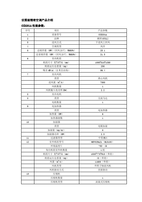
世图兹精密空调产品介绍CCD201A性能参数:德国世图兹Minispace系列机房专用空调介绍Minispace系列描述:Minispace机组特点:德国STULZ Minispace 产品,该产品系列在同行业产品中,技术成Minispace空调产品系列是在采用新的设计理念和创新技术而形成的经典一代高可靠性和高科技产品系列。
该系列产品具有独特的性能特点:节能、高可靠性、环保、低噪、风量大、方便。
1、STULZ Minispace系列空调具有高显热比特点:通讯机房内电子设备释放出大量的显热。
Minispace针对机房特点实现0.9以上的高显热比,在机房环境下使用,相对于普通舒适性空调节省20-30%的能耗,并因此避免过度除湿和送风带雾。
2、功能强大的新一代C5000微处理控制器控制器是空调系统的核心。
在以前C1002控制器的基础上性能有了进一步的提高,技术不断更新的STULZ新一代的控制器 C5000采用先进的“模糊”控制理论作为其控制的基础,可对机房环境-温度、湿度、洁净度进行连续的24小时精密控制,并具有自学习、分析、预测、自动控制功能,是一种新型智能控制器。
1)大屏幕汉语显示,方便用户使用;2)可显示24小时温、湿度曲线,简学、清晰、明显;3)可实现对空调机组的分散独立的智能化控制;4)记录各功能部件的运行时间,如制冷、加热、加湿、除湿等;5)80条报警记录,且有断电数据保护;6)在机组出现高压或者低压警告和停机,可实现自动重启功能,停电机组也具有来电自启动功能,避免不必要的到场工作,满足无人值守的要求;7)控制板可配置标准RS485通信接口,,与 BMS 连接时无需额外的硬件支出,可接打印机;8)机房参数的三级控制:参数新型的显示监控,报警参数的设置,系统基本功能的设置。
所有参数都有断电记忆保护,并能在断电恢复后自动延时启动机组;9)精密控制:所有模块可设置成以温度为0.3℃为梯度的制冷模块,当热负荷增加时自动加载,模块可故障自停和自投、高效节能;湿度以1%RH为梯度进行设置;10)全面的自动自检测:具有自动检测并具有双控制器功能,可增加一台控制器作为监控器使用。
APCH样本

直接式自然冷却系统
间接式自然冷却系统
5
i-MASTER 微处理控制系统
AIRFACT 功能强大的 I-MASTER 电脑控制系统控制机组的运行,它根据系统需求负荷的大小,启动/关闭压缩 机的运行,或使压缩机工作在一定的负荷输出下。电脑控制其监测每一个系统以及每一个压缩机的运行状态, 当机组发生故障时,关闭故障单元的运行。
冷媒与制冷回路
机组采用 R22 或 R134A 冷媒,每 一台机组具有两个独立的制冷回 路,他们包括了螺杆式制冷压缩 机、冷凝器、蒸发器、干燥过滤器、 具有湿度指示的视液镜、液体管路 电磁阀、电子膨胀阀等。机组在出 厂时已经经过了压力检验,并灌注 了冷媒。所有的低温管道都包有保 温隔热层。
3
带有自然冷却的 APCH-FD/FS 机组
AIRFACT 不断致力于为市场提供节 能、环保,以及高可靠性和低费用的 新技术和新产品。APCH 系列风冷冷 水机组及自然冷却机组专为 IT 和工 业制冷应用而设计
AIRFACT
1959 年,AIRFACT 创立于澳大利亚悉尼。它是澳大 利亚最早的本土制冷空调产品品牌。 创立以后的 AIRFACT,生产制造了大量的屋顶式空调 机组、分体式空调机组、风管式空调机组、整装式冷 水机组等。这些产品在澳大利亚制冷空调市场占据了 重要的地位。 2000 年悉尼奥运会,AIRFACT 和全球最大螺杆压缩 机制造商 BITZER 合作成为悉尼奥运会合作伙伴,再 次发挥了重要的作用,为大量的奥运会设施提供了高 质量的制冷空调设备。 2003 年,AIRFACT 在中国深圳建立了一个新的工厂, 并将业务范围从商用空调市场扩展到了新兴的 IT 领 域,为 IT 应用提供包括冷却系统和机架系统在内的 IT 物理基础设施产品。 今天,有着超过 50 年历史的 AIRFACT,继续不断创 新和探索新技术,为顾客提供节能、节省费用的高质 量产品。
APC技术参数
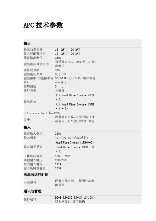
APC技术参数输出输出功率容量16 kW / 20 kVA 最大可配置功率16 kW / 20 kVA 额定输出电压230V输出电压可调范围可设置为220、230或240 输出电压满负载效率94%输出电压失真低于 5%输出频率(与主频率同步) 50/60 Hz +/- 3 Hz 用户可调+/- 0.1波峰因数 3 : 1 波形类型正弦波输出连接(1) Hard Wire 3-wire (H N + G)(1) Hard Wire 5-wire (3PH + N + G)efficiency_half_load94%旁路内置静态旁路,内部旁路 (自动会人工),外置分路器可选输入额定输入电压230V输入频率40 - 70 Hz(自动感测)输入端子类型Hard Wire 3 wire (1PH+N+G) Hard Wire 5-wire (3PH + N + G)工作电压范围160 - 280V 其他输入电压220,240最大输入电流111A输入断路器容量125A电池与运行时间电池型号没有内部电池 - 使用外部电池系统通讯与管理接口端口DB-9 RS-232,RJ-45 10/100 以太网接口,灵巧插槽预装SmartSlot™ 卡AP9619控制面板多功能液晶显示器状态管理控制台。
有声报警Audible and visible alarms prioritized by severity紧急关断Yes 浪涌保护及滤波滤波器多级噪声滤波器,符合UL1449标准物理指标高263.00 mm宽432.00 mm深773.00 mm设备安装有效高度6U净重68.00 KG运输重量129.09 KG运输高度622.00 mm运输宽度610.00 mm运输长度1003.00 mm颜色黑色每个运输托盘上产品数量1.00环境工作环境0 - 40 °C工作相对湿度0 - 95%操作高度0-3000米存储温度-15 - 45 °C存储相对湿度0 - 95%存储高度0-15000米听觉噪音距设备表面 1m 处59.00 dBA在线运行发散热量3487.00 BTU/hr 相符性管理机构认证EN/IEC 62040-2,EN/IEC 62040-1-1标准质保 2 years repair or replace。
伊莱克斯电磁阀说明书
外 形 尺 寸 OV E R ALL DIM E N S IO N S (m m )
FG6 Rp 2"
56
2/ 6 208 128 182 2000 330
C
GAS FLOW CHART (PRESSURE DROP)
A C
B B
A
Description The VMR type is a fast opening and fast closing solenoid valve that is normally closed. When not energized the spring works on the seat keeping the gas passage closed. When the coil is powered the valve is rapidly opened.If the power supply is shut off,the valve rapidly closed.
FLOW FACTOR
KVS(m 3/h)
VM R 01--OT N VM R 02--OT N VM R 12--OT N
VMR0 VM R 12-A
VMR1 VMR2 VMR3 VM R35 VMR4 VMR6 VM R4F VM R6F VMR7 VMR8 VMR9 VM R93 VM R95
-
-
2.50
Parker Hannifin Corporation 零温度方向控制阀Viking系列P2L-A、
Directional Control ValvesLow Temperatu re Viking SeriesP2L-A, 1/8 - 27 NPTFP2L-B, 1/4 - 18 NPTFP2L-D, 1/2 - 14 NPTFCatalog 0677!WARNINGFAILURE OR IMPROPER SELECTION OR IMPROPER USE OF THE PRODUCTS AND/OR SYSTEMS DESCRIBED HEREIN OR RELATED ITEMS CAN CAUSE DEATH, PERSONAL INJURY AND PROPERTY DAMAGE.This document and other information from Parker Hannifin Corporation, its subsidiaries and authorized distributors provide product and/or system options for further investigation by users having technical expertise. It is important that you analyze all aspects of your application including consequences of any failure, and review the information concerning the product or system in the current product catalog. Due to the variety of operating conditions and applications for these products or systems, the user, through its own analysis and testing, is solely responsible for making the final selection of the products and systems and assuring that all performance, safety and warning requirements of the application are met.The products described herein, including without limitation, product features, specifications, designs, availability and pricing, are subject to change by Parker Hannifin Corporation and its subsidiaries at any time without notice.Offer of SaleThe items described in this document are hereby offered for sale by Parker Hannifin Corporation, its subsidiaries or its authorized distributors. This offer and its acceptance are governed by the provisions stated on the separate page of this document entitled “Offer of Sale”.© Copyright 2004, Parker Hannifin Corporation. All Rights Reserved.2Directional control valvesVikingSummary Page General information (5)Order key (6)Flow characteristics (7)Technical data............................................................................................7-8 Main data, pneumatically actuated.. (9)Dimensions, pneumatically actuated.......................................................10-11 Main data, electrically actuated, complete valves for 24 V AC/DC. (12)Main Data, electrically actuated (supplied without solenoid valves) (13)Dimensions, electrically actuated............................................................14-15 Main data, hand operated, lever 90° to ports (16)Dimensions, hand operated, lever 90° to ports........................................17-18 Main data, hand operated, lever in line with ports.. (19)Dimensions, hand operated, lever in line with ports (20)Main data, hand operated, manual locking (21)Dimensions, hand operated, manual locking (22)Solenoid valves order key (23)Solenoids 15mm NC, mobile (24)Cable plugs (25)Solenoid dimensions (26)Offer of sale (27)Conversion factors1 kg= 2.2046 lb1 N= 0.22481 lbf1 bar= 14.504 psi1 l= 0.21997 UK gallon1 l= 0.26417 US gallon1 cm3= 0.061024 in31 m= 3.2808 feet1 mm= 0.03937 in9/5 °C + 32 = °F34Directional control valvesVikingThe Viking valve range is robust, versatile and combines high performance with compact installation dimensions. Large flow capacity, short change-over times and low change-over pressure are important characteristics of this valve range.Viking valve rangeP2L-A, dimension 1/8 - 27 NPTF, P2L-B, dimension 1/4 - 18 NPTF, P2L-D, dimension 1/2 - 14 NPTFThe P2L-A, P2L-B and P2L-D have a wide range of hand, foot,pneumatic and electrically operated valves in both 5/2 and 5/3configurations.The Viking range is available in both standard and low temperature versions.5Directional control valvesVikingCompact dimensions, direct body porting and integral mounting holes are all features of the Viking range In addition to simple single installation, the Viking range may be installed in very compact blocks.Rust and corrosion resistant designs.Viking valves are made entirely of anodized aluminium, forcorrosion resistance. The smooth design, with no dirt-collecting pockets, makes the valve suitable for most environments,including applications with stringent hygiene requirements. The valve has stainless steel screws for the end covers, to withstand aggressive environments.Mobile applicationsCommission and service is facilitated by the generously sized,ergonomically designed buttons for manual operation on the P2L-B valve range, which are a standard feature. These make it very easy to see the valve spool position during fault finding.A wide range of solenoid valvesA robust anodized aluminium valve housing, standard and low-temperature versions, hand lever with built-in catch for reliable retention in position, variants designed for a special NO (normally open) mobile solenoid valve, and several varieties of specialmobile (NC) solenoid valves make the valve an excellent choice in mobile applications.High reliabilityManual override - indication on the P2L-BA number of different versions of our solenoid valves P2E with 15 mm DIN 43650 form C enclosures are available to suit justabout any application. The valve has small installation dimensions,low energy consumption, large flow diameter, large flow capacity,a robust valve body, high reliability and long service life. With or without flush locking, extended non locking manual override, with long or short arm, spring biased or indexing.Low noise levelThe exhaust air from the pilot valves is exhausted through a silencer located in the end cover or body, to give the lowest possible noise level. This is particularly important for industries where low noise levels are required. The silencers make it possible for the valves to comply with the EU Machinery Directive,Noise 1.5.8.CertificationThe solenoid valves are protection class IP65 with the standard cable plug. The cable plug with reinforced protection raises the protection standard to IP67.Several types of cable plugsCompact installation dimensions - flexible installationValves easily comply with the requirements for componentreliability in accordance with the EU Machinery Directive standards EN292-2 and EN983.In the P2L-A: few moving parts combined with short spoolmovement give a valve with high reliability and long service life. It is designed for use with, or without supplementary lubrication.In the P2L-B and P2L-D: high molecular weight plastics with self-lubricating properties make it suitable for use with, or without supplementary lubrication.MaintenanceSize A and B spare parts = new valve.With or without suppression, LED and rectifier. For connection to your own cables or with molded cable. A large selection allows you to choose cables to meet your requirements.Insensitive to dirty airThanks to large flow passage areas and the large flow diameter of 1.0 in the pilot valves, the P2L-A, P2L-B and P2L-D can be used in normal industrial or mobile environments without any problems of sticking. However, the service life of the valve depends on thecleanliness of the air. Please refer to ISO 8573.Directional control valves Viking Order key67Flow characteristicsFlow capacities in accordance with ISO6358.All pressures = effective pressureThe curves in the diagram below are typical only.P2L-AP2L-BDirectional control valvesVikingP2L-DTechnical dataP2L-ADimension1/8 - 27 NPTFOperating pressure, max 145 psi (10 bar)* Also see “Operating pressure”.Operating temperature range for directional control valves low temp. version-40 to 86 °F (–40 to +30 °C)Operating temperature range for P2E solenoid valves mobile version -40 to 158 °F (–40 to +70 °C)FlowCv=0.76(Flow acc. to ISO 6358)(C=3,0 Nl/s x bar)(b=0.3)(Qn=12.7 l/s)(Qmax=21.0 l/s)P2L-BDimension1/4 - 18 NPTFOperating pressure, max 145 psi (10 bar)* Also see “Operating pressure”.Operating temperature range for directional control valves low temp. version-40 to 86 °F (–40 to +30 °C)Operating temperature range for P2E solenoid valves mobile version -40 to 158 °F (–40 to +70 °C)FlowCv=1.0(Flow acc. to ISO 6358)(C=4.2 Nl/s x bar)(b=0.2)(Qn=17.0 l/s)(Qmax=29.4 l/s)P2L-DDimension1/2 - 14 NPTFOperating pressure, max 145 psi (10 bar)* Also see “Operating pressure”.Operating temperature range for directional control valves low temp. version-22 to 86 °F (–30 to +30 °C)Operating temperature range for P2E solenoid valves mobile version -40 to 158 °F (–40 to +70 °C)FlowCv=2.9(Flow acc. to ISO 6358)(C=12 Nl/s x bar)(b=0.2)(Qn=48.0 l/s)(Qmax=84.0 l/s)3003x1056006x1059009x105120012x105150015x105180018x105210021x105Flow [l/s][l/min][Sccm]6001200180024003000[l/min]Flow[l/s]6x10512x10518x10524x10530x105[Sccm]1200240036004800600072008400[l/min]Flow[l/s]12x10524x10536x10548x10560x10572x10584x105[Sccm]8Material specificationP2L-A ValveValve body Anodized aluminium End coversAnodized aluminium or Reinforced thermoplasticLever housing Acetal plastic Spool Aluminium + nitrile rubber Piston Acetal plastic/ Anodized aluminium U-rings, O-rings Nitrile rubber End cover sealings Nitrile rubber End cover screws Stainless steel Springs Dacromet® - processed steel,Stainless steelLever Reinforced polyamid plastic Panel mounting nut Polycarbonate plastic Gaiter Chloroprene rubber Mounting screws for solenoid Stainless steelP2L-B ValveValve body Anodized aluminium Spool Acetal plastic/ Anodized aluminiumPistonAcetal plastic /Anodized aluminiumLiningReinforced thermoplastic End covers Anodized aluminium Sliding seals Thermoplastic U-rings, O-rings Nitrile rubber End cover sealings Nitrile rubberPush button for manual changeoverAcetal plastic End cover screws Stainless steel Springs Stainless steel LeverZinc-plated steel Catch for lever Stainless steelKnob Phenolic plastic/Anodized aluminium Gaiter Chloroprene rubber Foot pedalAluminiumMounting screws for solenoidZinc-plated steelDirectional control valvesVikingP2L-D ValveValve body Anodized aluminium Spool Anodized aluminium Piston Brass LiningBrassEnd covers Anodized aluminium Sliding seals Thermoplastic U-rings, O-rings Nitrile rubber End cover sealings Nitrile rubber End cover screws Stainless steel Springs Stainless steel LeverStainless steel Catch for lever Zinc-plated steel Knob Thermoplastic GaiterNitrile rubber Distance ringThermoplasticMounting screws for solenoidZinc-plated steelDimensions* Operating pressureFrom 0 to 145 psi (10 bar) connectable in all portsThis is valid with the following exceptions:Electrically actuated valves•If supply pressure is connected to any other port than port 1 [port 1 also provides supply pressure to solenoid(s)] or if the air supply pressure is lower than minimum signal pres-sure it is necessary to use valves with external air supply to solenoid(s。
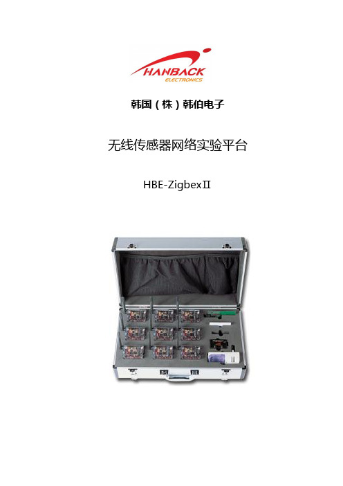
韩伯电子 无线传感器网络实验平台HBE-ZigbexII
臭氧检测模块
一氧化氮检测
一氧化氮检测模块
韩国(株)韩伯电子北京代表处
010-8446-6697 4
名称 挥发性有机气体检测模块
描述 挥发性有机气体检测模块
图片
TN9
非接触型体温计模块
RFID 读卡器
射频识别读卡器模块
电池
提供电源模块
4.1 可选传感器模块的规格
4.1.1
数字输入输出
电机控制
4.1.2
名称
HealthCare
参数 - 感测脉搏及体温传感器 1. Heart Beat : 测定心跳 * 传感器 : Instrumentation Type * 通道 : 心电图 * 输出 : 模拟输出
BIO 心跳、体温检测
2. 体温 : 测体温(非接触型) * 传感器 : GE ZTP115 * 通道 :非接触式周围温度影响的温度补偿 * 温度范围 : -20℃~100℃ * 工作电压 : 2.7~5.5 V * 输出 : 模拟输出 - 测定血压/血糖传感器 1. 血糖 * 测量范围 : 20 ~ 600mg/dL(1.1 ~ 33.3 mmol/L) * 表示单位 : mg/dL, mmol/ * 血液量 : 最少 0.5 ㎕ l * 测量时间 : 5 秒
4 可选传感器模块及技术参数
名称 气象传感器模块 描述 温湿度、红外线、红外线、大气压、震动 图片
HA1 传感器模块
接近传感器、人体感知(远红外线传感器)
HA2 传感器模块
气体传感器、磁性传感器
位置跟踪传感器
GPS 传感器
生物传感器模块
脉搏用传感器、体温用传感器
Relay 模块
继电器模块
USB 模块
APC产品线介绍

A P C(含梅兰日兰)产品总揽一.1.UPSMGEGalaxy6000,Galaxy9000功率段:250KVA300KVA400KVA500KVA600KVA800KVAMGEGalaxy7000功率段:160KVA200KVA250KVA300KVA400KVA500KVASymmetraMW(模块化UPS)功率段:400KW600KW800KW1000KW1200KW1400KW1600KWSymmetraPX(英飞组成部分,模块化UPS,25KW一个模块)功率段:100KW125KW150KW200KW250KW300KW400KW500KW2.静态切换开关UpsilonSTS30A60A100A160A250A400A600A800A1200A1600A2000A3.电源管理模块PMM250A4.配电单元PDU(100-4000A)5.有源谐波调节器SineWave20A30A45A60A90A120A6.零序谐波滤波器CleanWave功率段:12KVA18KVA30KVA40KVA55KVA90KVA140KVA180KVA220KVA280KV A7.制冷优力(Uniflair)功率段:5.2KW-135KW二.中型数据中心1.UPS1)SymmetraPX(英飞组成部分,模块化UPS,16KVA一个模块) 功率段:16KVA32KVA48KVA64KVA96KVA128KVA160KVA模块化电源分配系统(扩容,升级用)138KW277KW2)MGEGalaxy5000功率段:20KVA30KVA40KVA60KVA80KVA100KVA120KVA2.制冷1)模块化,仅靠热源针对高热密度空调InRowRCACRC103(冷冻水型)制冷量最高30KWACRC502(冷冻水型)制冷量最高60KWInRowRDACRCD101(DX风冷型)制冷量2-10KWACRD201(DX水冷型)制冷量2-11KWACRCD502(DX风冷型)制冷量10-37KWInRowRPACRP102(DX直接膨胀型)制冷量10-37KWACRP502(CW冷冻水型)制冷量最高70KW2)优力空调5.2-135KW三.小型数据中心和服务器机房1.UPS1)Smart-upsVT功率10KVA15KVA20KVA30KVA40KVA2)MGEGalaxy3000功率:10KVA15KVA20KVA30KVA3)Comet3000功率:15KVA20KVA30KVA40KVA60KVA80KVA4)MGEGalaxy3500功率:10KVA15KVA20KVA30KVA5)SymmetraLX(小英飞,模块化UPS,4KVA一个模块)功率段:4-16KVA6)Smart-ups塔式(在线互动式)功率段750/1000/1500/2200/3000/5000VASmart-ups机架式(在线互动式)功率段750/1000/1500/2200/3000/5000VASmart-upsRT(纯在线式,机架和塔式通用)功率段:1/2/3/5/8/10/15/20KVASRC(纯在线式,机架和塔式通用)功率段:1/2/3/5/6/8/10KVASmart-upsSC功率段:250/450/420/620/1000/1500VA2.制冷1)InrowSC(模块化,仅靠热源高热密度机密空调)ACSC101(DX风冷型)制冷量最高7KW2)优力空调四.工业领域MGEGalaxypw/1000PW功率段:20/30/40/50/60/80/100/120/160/200KVA 五.桌面和移动设备1.UPSBack-ups/CS/RS(后备式)功率段500/650/1000VA2.浪涌保护电源净化插座六.英飞中央管理器七.安全及环境监测解决方案NetBotz八.服务器访问解决方案机柜KVM九.机柜系统AR3100AR3150AR3300AR3350AR3107AR3157AR3307AR3357 十.1.机架式配电单元基本型PDU计量型PDU开关型PDU2.机架式ATS(10A16A32A)3.机柜附件4.气流管理选件Guangcan?Gong?龚光灿|??APCbySchneiderElectric??|?ITBusiness?|??FieldEvangelistTeam???? 400免费客服电话:400-810-1315?|Email:??Site:?。
4020总碳氢分析仪

仪器序列号包含选项信息: □ 电源需求:本仪器可以设计成常用操作电源,除了 115VAC@60Hz。请查看包装箱上指
示确认您仪器的电源。 □ 110VAC@50HZ □ 115VAC@50HZ □ 220VAC@50HZ □ 其它: □ 氢气为样气:在这种配置中氢气为样气同时作为燃料气。本配置在仪器后面的管路连接
警告:电击危险!仪器有危险电压,警告特指有电击危险的组成部分或操作 流程。忽视警告可能导致人身伤亡。
技师标志:凡是有此标志的操作都必须由有专业维护资格的人员完成。
NOTE:其余的有关特殊部分或流程的信息和注释用 note 突出显示。
STAND-BY:此标志显示仪器待机,但回路依然运作。
注意:本仪器应该用于本手册中的目的,并严格按照说明操作。 如果仪器挪作他用或操作有误,可能导致严重后果。
安装................................................................................................................................. 13
3.1 分析仪开箱............................................................................................................. 13 3.2 安装分析仪............................................................................................................. 13 3.3 用户连接部分 ......................................................................................................... 13
APC-4013 尘埃粒子计数器使用说明书
1.概述 (2)2.主要技术参数 (2)3. 工作原理 (3)4. 屏幕显示说明 (3)4.1开机画面 (3)4.2 参数设置画面 (4)4.3 实时数据画面 (5)4.4 存储数据画面 (7)5.功能说明 (8)5.1 按键说明 (8)5.2 画面切换 (9)5.3 参数设置 (9)5.4 测量 (10)5.5 打印 (13)6.维护及故障修理 (17)6.1 仪器使用、存贮的注意事项 (17)6.2 常见故障与排除方法 (17)7.附录 (18)1.概述APC型激光尘埃粒子计数器(以下简称仪器)用于测量洁净环境中单位体积空气内的尘埃粒子大小及数目,可作为判定洁净度等级的依据。
本仪器采用半导体激光光源,液晶屏显示,其体积小、重量轻、检测精度高、功能操作简单明了,电脑控制,可贮存、打印采样结果,测试洁净环境十分便利,广泛应用于电子、光学、化学、食品、化妆品、医药卫生、生物制品、航空航天等部门。
2.主要技术参数2.1允许最大采样浓度:3.5万颗/L2.2最小可测粒径:0.3µm2.3粒径通道:0.3µm、0.5µm、1.0µm、2.0µm、3.0µm、5µm六档2.4空气采样流量:2.83L/min2.5采样时间PE(即采样量):1min~10min共10种采样时间可选(即:2.83L、5.66L、8.49L…………28.3L共十种采样量可选)2.6自净时间:≤ 10min2.7测量方式:分手动(Man)和自动(Auto)自动测量时,房间号(Room)自动编号(1~20)每点的测量次数(Cyc)可设置(2∼99)采样点数(Loc)可设置(1∼99)2.8打印方式:可自动打印,也可选择打印存储数据2.9打印格式:分ALL、UCL二种2.10液晶屏尺寸:144mm×104mm2.11外型尺寸:235×115×295(mm)2.12重量:4.5kg2.13电源:220V 50Hz , 40W2.14使用环境条件温度:10℃——30℃湿度:20%——75%大气压力:86kPa——106kPa3. 工作原理本仪器采用光散射原理,当空气中悬浮粒子经过光敏区时,散射出与其粒径成一定比例的光通量,经光电转换、放大及处理后得到被采集粒子当量直径和数量。
巴克尔(Parker)空气准备系统产品目录说明书

Pneumatic Air Preparation Systems Optional Port Block Kits• To change port sizes Port Block Kits are available, they are attached to any unit utilizing the connecting kit.• Allows assemblies to be removed from a hard pipedsystem.Modular ManifoldP3Y Series Manifolds provide up to 4 extra outlet ports. They may be assembled at any position in a combination e.g. before the lubricator to provide oil free take off or at theend of a combination to provide extra outlet ports.Port sizesInlet port Top Bottom Front and Back 3/4"1/8”1”1/4”1"1/8”1”1/4”G1AccessoriesMaterial specificationsBody Aluminium Weight0.65 kg (1.43 lb)Material specificationsBody Aluminium Weight0.7 kg (1.5 lb)Dimensions mm (inches)Pneumatic Air Preparation SystemsSolenoid OperatorsSolenoid Operators - CNOMO MaterialsTechnical data -Solenoid operators, coil combinationsPilot ValveBody:Polyamide Armature tube:BrassPlunger & core:Corrosion resistant Cr-Ni steel Seals:Fluorocarbon Screws:Stainless steelCoilEncapsulation material:Thermoplastic as standard Duroplast for M12 connectionTransientsInterrupting the current through the solenoid coil producesmomentary voltage peaks which, under unfavorable conditions, can amount to several hundred times the rated operating voltage. Normally, these transients do not cause problems, but to achieve the Maximum life of relays in the circuit (and particularly of transistors, thyristors and integrated circuits) it is desirable to provide protection by means of voltage-dependent resistors (varistors). All connectors/cable plugs EN175301-803 with LED’s include this type of circuit protection.Solenoid Coils with M12 ConnectionSolenoid Coils with DIN A or Industrial B Connectionabove part numbers for spares. The operators are supplied with mounting screws and interface ‘O’ rings. Coils and connectors must be ordered separately.22mm x 30mm 30mm x 30mm Part number Spare Base Solenoid Pilot Operator CNOMO NCNC Normal Operator with 22 x 30 standard coilNC Normal Operator with 30 x 30 standard coil Working pressure 0 to 10 bar 0 to 10 bar Ambient temperature -10°C to 60°C *-10°C to 60°C *Power (DC) 4.8W 2.7W Power (AC)8.5VA 4.9VA Voltage tolerance +/-10%+/-10%Duty cycle 100%100%Insulation class FFElectric connection B Industrial DIN 43650A Protection IP65IP65Approval UL/CSAWorking mediaAll neutral media such as compressed air* Limited to 50°C if use with 100% duty cyclePneumatic Air Preparation SystemsSolenoid Nuts, Connectors & CablesSolenoid Connectors / Cable Plugs EN175301-803Part number 22mm Form B Part number 30mm Form A Solenoid coil dimensions mm (inches)Cable plug dimensions mm (inches)Electrical schematics22mm Form B industrial cable plugs22 x 30mm30 x 30mm30mm DIN 43650A cable plugs。
cd4024中文资料pdf

15/0
VIL 输入低电 0.5/4.5
-
平电压
1.0/9.0
(最大) 1.5/13.5
VIH 输入高 4.5/0.5
-
电平电压 9.0/1.0
(最小) 13.5/1.5
IOH 输出高电 2.5
5/0
平电流
4.6
5/0
(最小)
9.5 10/0
13.5 15/0
5.0 10.0 15.0
5.0 10.0 15.0
15.0 5.0 10.0
15.0
tTLH、tTHL 输出转换时间
5.0
-
360
ns
160
130 200 80 60 200
m o cns
10.0 15.0
100 80
.
fcp
CP 频率
tw
CP 脉冲宽度
5.0 10.0 15.0 5.0 10.0
3.5 8.0 12.0 -
m -
MHz
r140 a60
5.0 10.0 15.0
5.0 10.0 15.0
5.0 -2.0 5.0 -0.64 10.0 -1.6 15.0 -4.2
-1.8 -0.61 -1.5 -4.0
0.05
V
4.95 9.95 14.95
1.5
V om cV
3.0 4.0
3.5
. mV
7.0
r 11.0 a -1.6
-0.51
ww
15.0 5.0 10.0
60 350 150
15.0
100
- -1.3 a-3.4
-1.3 -0.42 -1.1 -2.8
-1.15 -0.36 - 0.9 -2.4
西门子2-3通电磁阀40毫米行程电液伺服执行器SKC32... SKC82... SKC62...
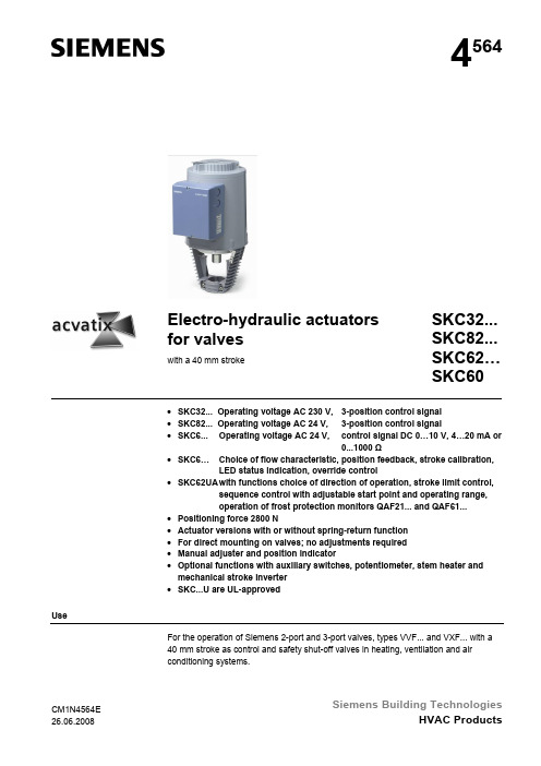
4564Electro-hydraulic actuators for valveswith a 40 mm stroke SKC32... SKC82... SKC62…SKC60•SKC32... Operating voltage AC 230 V, 3-position control signal•SKC82... Operating voltage AC 24 V, 3-position control signal•SKC6... Operating voltage AC 24 V, control signal DC 0…10 V, 4…20 mA or0...1000 Ω•SKC6… Choice of flow characteristic, position feedback, stroke calibration,LED status indication, override control•SKC62UA with functions choice of direction of operation, stroke limit control,sequence control with adjustable start point and operating range,operation of frost protection monitors QAF21... and QAF61...•Positioning force 2800 N•Actuator versions with or without spring-return function•For direct mounting on valves; no adjustments required•Manual adjuster and position indicator•Optional functions with auxiliary switches, potentiometer, stem heater andmechanical stroke inverter•SKC...U are UL-approvedUseFor the operation of Siemens 2-port and 3-port valves, types VVF... and VXF... with a40 mm stroke as control and safety shut-off valves in heating, ventilation and airconditioning systems.CM1N4564ESiemens Building Technologies2/16Types Spring-return Positioning timeTypeOperating voltagePositioning signal Function Time Opening Closing Enhanced functionsSKC32.60SKC32.61 AC 230 Vyes 18 s SKC82.60 SKC82.60U *SKC82.61 SKC82.61U *3-positionyes 18 s 120 sSKC62 SKC62U * yes 20 s Standard electronicsSKC60Enhanced electronicsSKC62UA *AC 24 VDC 0...10 V,4...20 mA,or 0...1000 Ωyes 20 s120 s20 syes 1)1)Direction of operation, stroke limit control, sequence control, signal addition *UL-approved versionsTypeDescription For actuator Mounting location ASC1.6 Auxiliary switchSKC6… ASC9.3 Dual auxiliary switches ASZ7.3Potentiometer 1000 Ω ASZ7.31 Potentiometer 135 Ω ASZ7.32 Potentiometer 200 Ω SKC32… SKC82… 1 x ASC 1.6 or 1 x ASC9.3 or 1 x ASZ7.3 or 1 x ASZ7.31 or 1 x ASZ7.32 ASZ6.5 Stem heater AC 24 VSKC…1 x ASZ6.5When ordering please specify the quantity, product name and type code. Example: 1 actuator, type SKC32.60 and 1 potentiometer, 135 Ω, type ASZ7.31The actuator, valve and accessories are supplied in separate packaging and not assembled prior to delivery.See overview, section «Replacement parts», page .15Equipment combinationsFor admissible differential pressures Δp max and closing pressures Δp s , refer to the relevant valve data sheets.Third-party valves with strokes between 12…40 mm can be motorized, provided they are «closed with the de-energized» fail-safe mechanism and provided that the necessary mechanical coupling is available. For SKC32… and SKC82… actuators theAccessoriesOrderingDelivery Spare partsNote3/16Y1 signal must be routed via an additional freely-adjustable end switch (ASC9.3) to limit the stroke.We recommend that you contact your local Siemens office for the necessary information.Technology1 Manual adjuster2 Pressure cylinder3 Suction chamber4 Return spring5 Solenoid valve6 Hydraulic pump7 Piston8 Pressure chamber 9 Position indicator (0 to 1) 10 Coupling 11 Valve stem12 Plug Valve closedValve openThe hydraulic pump (6) forces oil from the suction chamber (3) to the pressure chamber (8) and thereby moving the pressure cylinder (2) downwards. The valve stem (11) retracts and the valve opens. Simultaneously the return spring (4) is compressed.Activating the solenoid valve (5) allows the oil in the pressure chamber to flow back into the suction chamber. The compressed return spring moves the pressure cylinder upwards. The valve stem extends and the valve closesTurning the manual adjuster (1) clockwise moves the pressure cylinder downwards and opens the valve. Simultaneously the return spring is compressed.In the manual operation mode the control signals Y and Z can further open the valve but cannot move to the «0%» stroke position of the valve. To retain the manually set position, switch off the power supply or disconnect the control signals Y and Z. The red indicator marked «MAN» is visible.When setting the controller for a longer time period to manual operation, werecommend adjusting the actuator with the manual adjuster to the desired position. This guarantees that the actuator remains in this position for that time period. Attention: Do not forget to switch back to automatic operation after the controller is set back to automatic control.Turn the manual adjuster counterclockwise to the end stop. The pressure cylinder moves upward to the «0%» stroke position of the valve. The red indicator marked «MAN» is no longer visible.The actuator can manually be adjusted to a stroke position > 0 % allowing its use in applications requiring constantly a minimal volumetric flow.The SKC32.61, SKC82.61U and SKC62… actuators, which feature a spring-return function, incorporate an additional solenoid valve which opens if the control signal or power fails. The return spring causes the actuator to move to thePrinciple ofelectro-hydraulic actuatorsOpening the valveClosing the valveManual operation modeNote: Controller inmanual operationAutomatic modeMinimal volumetric flowSpring-return facility4/16«0 %» stroke position and closes the valve in accordance with the safety requirements set out in DIN 32730.The valve is controlled by a 3-position signal either via terminals Y1 or Y2 and generates the desired stroke by means of above described principle of operation. • Voltage on Y1 piston extends valve opens • Voltage on Y2 piston retracts valve closes • No voltage on Y1 and Y2 piston / valve stem remain in the respective positionThe valve is either controlled via terminal Y or override control Z. The positioning signal Y generates the desired stroke by means of above described principle of operation. • Signal Y increasing: piston extends valve opens • Signal Y decreasing: piston retracts valve closes • Signal Y constant: piston / valve stem remain in the respective position • Override control Z see description of override control input, page 7A frost protection thermostat can be connected to the SKC6… actuator. The added signals from the QAF21... and QAF61... require the use of SKC62UA actuators. Notes on special programming of the electronics are described under «Enhanced electronics» on page 5.«Connection diagrams» for operation with frost protection thermostat or frost protection monitor refer to page . 144567Z 031 Connection terminals2 Mode DIL switches3 LED status indication4 Slot for calibrationSKC32…/SKC82… 3-position control signalSKC62…, SKC60 Y control signal DC 0...10 V and/orDC 4...20 mA, 0…1000 ΩFrost protection monitorFrost protectionthermostatStandard electronics SKC62…, SKC60DIL switches SKC62…, SKC605/160163811 Connection terminals2 DIL switches3 LED status indication4 Stroke calibration 4 Rotary switch Up(factory setting 0) 5 Rotary switchLo* Factory settings: all switches OFFRelationship between control signal Y and volumetric flow04l i nl o gV YVV 010 V 20 mA• With normally-closed valves, «direct-acting» means that with a signal input of 0 V,the valve closes (applies to all Siemens valves listed under «equipment combinations» on page 2)• With normally-open valves, «direct-acting» means that with a signal input of 0 V, the valve is open.Direct actingReverse-acting100 %(10 V)100 %0 %YStrokeDir e c tR ev 0 V 4 mA 0 Ω20 mA 1000 ΩThe mechanical spring-return function is not affected by the direction of operation selected.Enhanced electronics SKC62UADIL switches SKC62UASelection of direction of operation SKC62UANote6/16* Operating range of QAF21... (see below)** Operating range of QAF61... (see below)*** The smallest adjustment is 3 V; control with 0…30 V is only possible via Y.Setting the signal additionThe operating range of the frost protection monitor (QAF21... or QAF61...) can be defined with rotary switches LO and UP.Position of LO Sequence control start point Position of UP QAF21... / QAF61...operating range 0 1 QAF21...0 2 QAF61...In order to determine the stroke positions 0 % and 100 % in the valve, calibration is required on initial commissioning: Prerequisites• • capture the effective 0 % and 100 % values • AC 24 V power supply • Housing cover removed Calibrationgreen LED flashes; position feedback U inactive1. Short-circuit contacts in calibration slot (e.g. with a screwdriver)2. Actuator moves to «0 %» stroke position (1) (valve closed)3. Actuator moves to «100 %» stroke position (2) (valve open)4. Measured values are stored 0%t100%S t r o k e1234567Z 09Normal operation5. Actuator moves to the position (3) asindicated by signals Y or Zgreen LED is lit permanently;position feedback U active, the values correspond to the actual positionsA lit red LED indicates a calibration error.The calibration can be repeated any number of times.Stroke limit control and sequence control SKC62UAStroke control with QAF21... / QAF61... signal addition SKC62UA onlyCalibrationSKC62…, SKC607/16The LED status indication indicates operational status with dual-colored LED and isAs a general rule, the LED can assume only the states shown above (continuously red or green, flashing red or green, or off).Override control input can be operated in following different modes of operationZ-modeno functionfully openclosedoverride with 0…1000 ΩSignal addition SKC62UA onlyC o n n e c t i o n sT r a n s f e r linear or equal-percentagelinear or equal-percentage linear or equal-percentage• Z-contact not connected • Valve stroke follows Y-input • Z-contact connected directly to G • Y-input has no effect • Z-contact connected directly to G0 • Y-input has no effect • Z-contact connected to M via resistor R • Starting position at50 Ω / end positionat 900 Ω• Y-input has no effect • Z-contact is connected to R ofthe frost protection monitor QAF21... or QAF61... • Valve stroke followssignals Y and R(Z)Shown operation modes are based on the factory setting «direct acting» Y-input has no effect in Z-mode.Indication of operating state SKC62…, SKC60Override control input ZSKC62..., SKC60Note8/16Accessories ASZ6.5 stem heaterfor media below 0 °C; mount between valve and actuatorASC9.3double auxiliary switchASZ7.3… potentiometeradjustable switching pointsASZ7.3: 0…1000 Ω ASZ7.31: 0…135 Ω ASZ7.32: 0…200 ΩASC1.6auxiliary switch5434561Z 08switching point 0…5 % strokeSee section «Technical data» on page for more information.11Engineering notesConduct the electrical connections in accordance with local regulations on electrical installations as well as the internal or connection diagrams.Safety regulations and restrictions designed to ensure the safety of people and property must be observed at all times!For media below 0 °C the ASZ6.5 stem heater is required to keep the valve from freezing. For safety reasons the stem heater is designed for an operating voltage of AC 24 V / 30 W.For this case, do not insulate the actuator bracket and the valve stem, as air circulation must be ensured. Do not touch the hot parts without prior protective measures to avoid burns.Non-observance of the above may result in accidents and fires!Recommendation: Above 140 °C insulating the valves is strictly recommended.SKC…SKC32…, SKC82…SKC62…, SKC609/16Observe admissible temperatures, refer to «Use» on page 1 and «Technical data» on page 1114If an auxiliary switch is required, its switching point should be indicated on the plant schematic.Every actuator must be driven by a dedicated controller (refer to «Connection diagrams», page ).Mounting instructionsMounting Instruction 74 319 0324 0 for fitting the actuator to the valve are by packed in the actuator packaging. The instructions for accessories are enclosed with the accessories themselves.Accessories Installation instructionsAccessory Mounting instructionsASC1.6 G4563.3 4 319 5544 0 ASZ6.5 M4563.7 4 319 5564 0 ASC9.3 G4561.3 4 319 5545 0 ASZ7.3… 74 319 0247 0 SKC… M3240 74 319 0324 0 ACTM4568 74 319 0554 0 SKC...74 319 0326 0QAF21…74 319 039990°4362Z 0190°Commissioning notesWhen commissioning the system, check the wiring and functions, and set any auxiliary switches and potentiometers as necessary, or check the existing settings.Cylinder with valve stem connector fully retracted Æ stroke = 0%Cylinder with valve stem connector fully extended Æ stroke = 100 %The manual adjuster must be rotated counterclockwise to the end stop.This causes the Siemens valves, types VVF... and VXF... to close (stroke = 0 %).For automatic operation, the crank (2) on the manual adjustment knob (1) must be engaged. If not engaged, turn the crank counter-clockwise until the display window (3) neither shows the scale (4) nor the crank engagement bar.124564Z 144564Z 16Engaged crank (2) on the manual adjustment knob (1) Display window with invisible scale dial and crank engagement barOrientationAutomatic operation10/16For manual operation, swing out the crank (2) so that the display window (3) becomes visible. By rotating the crank or the manual adjustment knob (1), the display window shows the engagement bar and/or the scale dial with stroke indication.34564Z 154Swung-out crank, display window (3)Display window with scale dial (4) and stroke indicationMaintenance notesThe SKC… actuators are maintenance-free. When servicing the actuator:• Switch off pump of the hydronic loop• Interrupt the power supply to the actuator • Close the main shutoff valves in the system• Release pressure in the pipes and allow them to cool down completely • If necessary, disconnect electrical connections from the terminals• The actuator must be correctly fitted to the valve before recommissioning.Recommendation SKC6…: trigger stroke calibration. «Replacement parts», see page . 15DisposalThe device contains electrical and electronic components and must not be disposed of together with domestic waste. This applies in particular to the PCB.Legislation may demand special handling of certain components, or it may be sensible from an ecological point of view.Current local legislation must be observed.WarrantyThe technical data relating to specific applications are valid only in conjunction with the valves listed in this Data Sheet under «Equipment combinations», page 2. The use of the actuators in conjunction with third-party valves invalidates all claims under Siemens Switzerland Ltd / HVAC Products warranty.Manual operationRepair11/16Technical dataSKC32… SKC82…, …U SKC6… Power supplyOperating voltage Voltage tolerance AC 230 V ± 15 % AC 24 V ± 20 % AC 24 V –20 % / +30 %SELV / PELV Frequency 50 or 60 Hz Max. Power consumption At 50 Hz SKC32.60: 19 VA / 16 W SKC32.61: 24 VA / 21 W SKC82.60, …60U 19 VA / 16 W SKC82.61, …61U 24 VA / 21 W SKC62…28 VA / 20 WSKC6024 VA / 18 WExternal supply cable fuse min. 0.5 A, slow max. 0.6 A, slow min. 1.6 A, slow max. 10 A, slow Signal inputs Control signal 3-position DC 0...10 V,DC 4...20 mA,0...1000 ΩTerminal Y Voltage DC 0…10 V Input impedance 100 k Ω Current DC 4…20 mA Input impedance 240 Ω Signal resolution < 1% Hysteresis 1 % Terminal Z Resistor 0…1000 Ω Override control Z not connected No function, priorityterminal YZ connected directly to G max. stroke 100 % Z connected directly to G0 min. stroke 0 % Z connected to M via 0...1000 Ω stroke proportional to R Terminal U voltage DC 0...9,8 V ±2 %Position feedbackInput impedance > 500 Ω Current DC 4...19,6 mA ±2 % Input impedance < 500 Ω Operating data Positioning time at 50 Hz opening SKC32.5… 120 s SKC82.5… 120 s 120 s Closing SKC32.5… 120 s SKC82.5… 120 s 20 s Spring-return time (closing) SKC32.61 18 s SKC32.60 – SKC82.61 18 s SKC82.60 –20 sPositioning force 2800 N Nominal stroke 40 mm Max. permissible medium temperature -25…150 °C< 0 °C: requires stem heater ASZ6.5Electrical connections Cable entry 4 x M20 (∅ 20,5 mm) Norms and standards CE-conformity EMC-directive 2004/108/ECImmunity EN 61000-6-2 Industrial Emission EN 61000-6-3 Residential Low voltage directive 2006/95/EC Electrical safety EN 60730-1 Product standards for automatic electric controlsEN 60730-2-14Protection standard EN 60730I IIIHousing protection standard Upright to horizontalIP54 to EN 60529SKC32… SKC82…, …U SKC6…ConformwithULstandardsSKC82…U UL 873SKC62U, SKC62UA UL873 C-tickN474Environmental compatibility ISO 14001 (Environment)ISO 9001 (Quality)SN 36350 (Environmentally compatible products)RL 2002/95/EG (RoHS)Dimensions / Dimensions refer to «Dimensions», page 15Weight Weight SKC32.60 10.00kgSKC32.61 10.50kg SKC82.60… 10.00 kgSKC82.61… 10.50 kgSKC6… 10.00kgMaterials Actuator housing, bracket Die-cast aluminumHousingboxandmanual adjusterPlasticAccessories SKC32…, SKC82… SKC6…ASC1.6 Auxiliary switch Switching capacity AC 24 V, 10 mA...4 Aresistive, 2 A inductiveASC9.3 double auxiliary switch Switching capacity per auxiliaryswitchAC 250 V, 6 A resistive, 2.5 A inductiveASZ7.3 Potentiometer Change in overall resistance ofpotentiometer at nominal strokeASZ7.3 0 (1000)ΩASZ7.31 0 (135)ΩASZ7.32 0 (200)ΩASZ6.5stem heaterOperating voltage AC 24 V ± 20 %Power consumption 30 VASKC62UA enhanced functionsDirection of operation Direct-acting, reverse-acting DC 0...10 V / DC 10...0 VDC 4...20 mA / DC 20...4 mA0...1000 Ω / 1000...0 ΩStroke limit control Range of lower limitRange of upper limit 0...45 % adjustable 100...55 % adjustableSequence control Terminal YStarting point of sequenceOperating range of sequence 0...15 V adjustable 3...15 V adjustableSignal addition Z connected to R ofFrost protection monitor QAF21... Frost protection monitor QAF61... 0...1000 Ω, added to Y signal DC 1.6 V, added to Y signalGeneralambient conditionsOperationEN 60721-3-3TransportEN 60721-3-2StorageEN 60721-3-1 Environmental conditions Class 3K5 Class 2K3 Class 1K3 Temperature -15...+50 °C -30...+65 °C -15...+50 °CHumidity5...95 % rh < 95 % rh 5...95 % rh12/1613/16Internal diagrams SKC32.61AC 230 V, 3-PositionSKC32.60AC 230 V, 3-PositionCm1 end switch nsolenoid valve for spring-returnc1, c2 ASC9.3 double auxiliaryswitch a, b, c ASZ7… potentiometerY1 Positioning signal «open» Y2Positioning signal «close»21 spring-return function N neutral conductorSKC82.61AC 24 V, 3-PositionSKC82.60AC 24 V, 3-PositionCm1 end switch nsolenoid valve for spring-returnc1, c2 ASC9.3 double auxiliaryswitch a, b, c ASZ7… potentiometerY1 Positioning signal «open» Y2Positioning signal «close»21 spring-return function G System potentialSKC60, SKC62SKC60U, SKC62U SKC62UAAC 24 V, DC 0…10 V, 4…20 mA, 0…1000 ΩU position indication Z override control Y positioning signal M measuring neutralG0operating voltage AC 24 V: system neutral (SN) Goperating voltage AC 24 V: system potential (SP)Connection terminals U ZG0G Y M operating voltage AC 24 V: system neutral (SN) operating voltage AC 24 V: system potential (SP) Positioning signal DC 0...10 (30) V or DC 4...20 mA Measuring neutral (= G0)Position indication DC 0...10 V or DC 4...20 mAOverride control (functionality see page 7)c134501804SKC6…Auxiliary switch ASC1.614/16Connection diagrams SKC32.61 SKC32.60F1 temperature limiter N1, N2 controller Y1, Y2 actuators L Phase N neutral Y1 Positioning signal «open» Y2 Positioning signal «close» 21 Spring-return functionSKC82.61, SKC82.61USKC82.60, SKC82.60UF1 temperature limiter N1, N2controller Y1, Y2actuators SPSystempotential AC 24 V SNSystem neutralQ1, Q2 controller contacts Y1 Positioning signal «open» Y2 Positioning signal «close» 21 Spring-return functionY1 actuator N1 controller F1 temperature limiter F2 frost protection thermostatterminals: 1 – 3 frost hazard / sensor is interrupted(thermostat closes with frost)1 –2 normal operationF3 frost protection monitor QAF21... or QAF61... (for SKC62UA only) * G (SP) System potential AC 24 V G0 (SN) System neutral* Only with sequence control and theappropriate selector switch settings (see page 6)SKC32… AC 230 V 3-PositionSKC82…AC 24 V 3-PositionSKC6…AC 24 VDC 0…10 V, 4…20 mA, 0…1000 Ω15/16DimensionsAll dimensions in mm4564M 01* Height of actuator from valve plate = 300 mm s = >100 mm ⎧ Minimum clearance from ceiling or wall for mounting, ss = >200 mm ⎩ connection, operation, maintenance etc.Replacement partsOrder numbers for replacement partsCoverHand control 1)ClampStem connectionControl unitActuator typeSKC32.60 410455828 426855108 410355768 417856498 SKC32.61 410455828 426855108 410355768 417856498 SKC82.60 410455828 426855108 410355768 417856498 SKC82.60U 410455828 426855108 410356058 417856498 SKC82.61 410455828 426855108 410355768 417856498 SKC82.61U 410455828 426855108 410356058 417856498SKC62 410455828 426855108 410355768 417856498 466857488 SKC62U 410455828 426855108 410356058 417856498 466857488 SKC60 410455828 426855108 410355768 417856498 466857598 SKC62UA410455828 426855108 4103560584178564984668575181)hand control, blue with mechanical parts16/16 © 2002 – 2008 Siemens Building Technologies Ltd. Subject to alteration。
- 1、下载文档前请自行甄别文档内容的完整性,平台不提供额外的编辑、内容补充、找答案等附加服务。
- 2、"仅部分预览"的文档,不可在线预览部分如存在完整性等问题,可反馈申请退款(可完整预览的文档不适用该条件!)。
- 3、如文档侵犯您的权益,请联系客服反馈,我们会尽快为您处理(人工客服工作时间:9:00-18:30)。
SPEC NO:DSAD1489 APPROVED:J.LU
REV NO: V.1 CHECKED:Jee Lee
DATE:APR/05/2003 DRAWN:L.ZHANG
PAGE: 3 OF 4
元器件交易网
Recommended Soldering Pattern (Units : mm)
Tape SpecificatC NO:DSAD1489 APPROVED:J.LU
REV NO: V.1 CHECKED:Jee Lee
DATE:APR/05/2003 DRAWN:L.ZHANG
PAGE: 4 OF 4
Package Dimensions & Internal Circuit Diagram
D
Notes: 1. All dimensions are in millimeters (inches), Tolerance is ±0.25(0.01")unless otherwise noted. 2. Specifications are subject to change without notice.
Electrical / Optical Characteristics at TA=25°C °
Sy m b o l VF IR X Chromaticity Coordinates Y c capacitance White White 0.34 65 pF VF=0V,f=1MHz P ar am et er Forward Voltage Reverse Current White White 0.33 D ev i c e Ty p . 3.65 Max . 4.2 10 Un its V uA Tes t Co n d it io n s I F =20mA V R = 5V
DATE:APR/05/2003 DRAWN:L.ZHANG
PAGE: 2 OF 4
元器件交易网
White
APCC02-41PWFA
APCC02-41PWFA SMT Reflow Soldering Instruction
Number of reflow process shall be less than 2 times and cooling process to normal temperature is required between first and second soldering process.
Absolute Maximum Ratings at TA=25°C °
P ar am et er Power dissipation DC Forward Current Forward Current (Peak)[1] Reverse Voltage Operating / Storage Temperature
SPEC NO:DSAD1489 APPROVED:J.LU
REV NO: V.1 CHECKED:Jee Lee
DATE:APR/05/2003 DRAWN:L.ZHANG
PAGE: 1 OF 4
元器件交易网
Selection Guide
P ar t N o . Dic e L en s Ty p e Iv (u c d ) @ 20 m A Min . APCC02-41PWFA WHITE (InGaN) YELLOW FLUORESCENT 7000 Ty p . 44600 Common Cathode, Rt. Hand Decimal D es c r i p t i o n
元器件交易网
SURFACE MOUNT DISPLAY
APCC02-41PWFA
WHITE
Features
!0.2INCH
Description
The source color devices are made with InGaN on SiC Light Emitting Diode.
Note: 1. 1/10 Duty Cycle, 0.1ms Pulse Width.
Wh it e 102 30 160 5 -40°C To +85°C
Un its mW mA mA V
SPEC NO:DSAD1489 APPROVED:J.LU
REV NO: V.1 CHECKED:Jee Lee
DIGIT HEIGHT.
!LOW CURRENT OPERATION. !EXCELLENT
CHARACTER APPEARANCE.
!I.C. COMPATIBLE !MECHANICALLY RUGGED. ! GRAY
FACE,YELLOW FLUORESCENT SEGMENT.
! PACKAGE : 1000PCS / REEL.