LA317LS8-XX-TR70中文资料
LM317
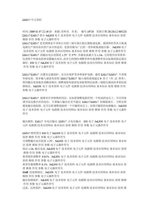
LM317中文资料时间:2009-02-07 22:19:53 来源:资料室作者:编号:19720 更新日期20120112 003228 LM117/LM317简介3xL838电子-技术资料-电子元件-电路图-技术应用网站-基本知识-原理-维修-作用-参数-电子元器件符号LM117/LM317是美国国家半导体公司的三端可调正稳压器集成电路。
我国和世界各大集成电路生产商均有同类产品可供选用,是使用极为广泛的一类串联集成稳压器。
3xL838电子-技术资料-电子元件-电路图-技术应用网站-基本知识-原理-维修-作用-参数-电子元器件符号LM117/LM317 的输出电压范围是1.2V 至37V,负载电流最大为1.5A。
它的使用非常简单,仅需两个外接电阻来设置输出电压。
此外它的线性调整率和负载调整率也比标准的固定稳压器好。
838电子3xL838电子-技术资料-电子元件-电路图-技术应用网站-基本知识-原理-维修-作用-参数-电子元器件符号LM117/LM317 内置有过载保护、安全区保护等多种保护电路。
通常LM117/LM317 不需要外接电容,除非输入滤波电容到LM117/LM317 输入端的连线超过6 英寸(约15 厘米)。
使用输出电容能改变瞬态响应。
调整端使用滤波电容能得到比标准三端稳压器高的多的纹波抑制比。
3xL838电子-技术资料-电子元件-电路图-技术应用网站-基本知识-原理-维修-作用-参数-电子元器件符号LM117/LM317 能够有许多特殊的用法。
比如把调整端悬浮到一个较高的电压上,可以用来调节高达数百伏的电压,只要输入输出压差不超过LM117/LM317 的极限就行。
当然还要避免输出端短路。
还可以把调整端接到一个可编程电压上,实现可编程的电源输出。
3xL838电子-技术资料-电子元件-电路图-技术应用网站-基本知识-原理-维修-作用-参数-电子元器件符号输出极性: LM117 负电压输出LM317 正电压输出838电子3xL838电子-技术资料-电子元件-电路图-技术应用网站-基本知识-原理-维修-作用-参数-电子元器件符号LM317特性简介838电子3xL838电子-技术资料-电子元件-电路图-技术应用网站-基本知识-原理-维修-作用-参数-电子元器件符号可调整输出电压低到1.2V。
三端稳压集成电路LM7中文资料

图7典型应用电路图
图8 TO-220封装图片
图9 D-PAK封装图
三端稳压集成电路LM7中文资料
部门:xxx
时间:xxx
制作人:xxx
整理范文,仅供参考,可下载自行修改
Electrical Characteristics电气特性(MC7824>LM7824
(参照测试电路,0°C< TJ <125°C, IO =500mA, VI =33V, CI=0.33ìF, CO=0.1ìF,除非另有说明>
(for VO =5V to 18V>
VI
35
V
(for VO =24V>
VI
40
V
Thermal Resistance Junction-Cases热阻(结到壳> (TO-220>
RθJC
5
℃/W
Thermal Resistance Junction-Air热阻(结到空气> (TO-220>
RθJA
Regline
TJ =+25℃
VI =27V to 38V
-
17
480
mV
VI =30V to 36V
-
6
240
Load Regulation负载调整率(Note1>
Regload
TJ =+25℃
IO =5mA to1.5A
-
15
480
mV
IO =250mA to 750mA
-
5.0
240
Quiescent Current静态电流
Parameter参数
LM317L 友顺UTC 电子元器件 芯片

-40 ~ +125
C
Storage Temperature Range
TSTR
-40 ~ +150
C
Note: Absolute maximum ratings are those values beyond which the device could be permanently damaged.
TMIN≦TJ≦TMAX
Minimum Load Current for Regulation Maximum Output Current
IL(MIN) IO(MAX)
VIN-VOUT=40V VIN-VOUT≦40V,PD<625mW
RMS Noise vs. %of VOUT
eN 10HZ≦f≦10KHZ
5 of 6
QW-R101-008.L
LM317L
LINEAR INTEGRATED CIRCUIT
UTC assumes no responsibility for equipment failures that result from using products at values that exceed, even momentarily, rated values (such as maximum ratings, operating condition ranges, or other parameters) listed in products specifications of any and all UTC products described or contained herein. UTC products are not designed for use in life support appliances, devices or systems where malfunction of these products can be reasonably expected to result in personal injury. Reproduction in whole or in part is prohibited without the prior written consent of the copyright owner. UTC reserves the right to make changes to information published in this document, including without limitation specifications and product descriptions, at any time and without notice. This document supersedes and replaces all information supplied prior to the publication hereof.
LM317T-XX-TR70中文资料
VIN-VOUT (V)
Rev. A/DX 2007-06-04 Page 4 of 8
元器件交易网 Typical Application
Adjustable Positive Voltage Regulator LM317
Fig.5-Programmable Voltage Regulator
Rev. A/DX 2007-06-04 Page 8 of 8
Typical Characteristics Curves
Fig.1- Load Regulation vs. Temperature
Fig.2- Adjustment Current vs. Temperature
IADJ, Adjustment Current (µA)
∆VOUT, Output Voltage Deviation (%)
Temperature (° C) Fig.3- Current Limit
Temperature (° C) Fig.4- Minimum Operating Current
IOUT, Min. Output Current (mA)
IOUT, Output Current (mA)
VIN-VOUT (V)
Rev. A/DX 2007-06-04 Page 1 of 8
元器件交易网 Pin Configuration
Adjustable Positive Voltage Regulator LM317
Outline: H SOT-223
Outline: T TO-220
Block Diagram
元器件交易网
Adjustable Positive Voltage Regulator
EM39LV088-70RD中文资料(ELAN Microelectronics)中文数据手册「EasyDatasheet - 矽搜」

X X X 见表3
写 命 令 /命 令 序 列
该EM39LV088提供两种软件方法来检测完成程序或 擦除,以优化系统写周期时间周期.软件检测包含 两个状态位:数据#查询(DQ7)和翻转位(DQ6).写操作结束检测模式 后WE#上升沿,从而启动内部编程或擦除已启用 操作.写操作实际完成是异步与系统; 因此,无论是数据#查询或翻转位读操作,可能是同时与完成 写周期.如果发生这种情况,则系统可能得到一个错误结果,即,有效 数据可能会与DQ7或DQ6冲突.为防止这样杂散 排斥,当一个错误结果发生时,软件程序应包括一个附加 两次循环读取访问位置.如果两个读取是有效,则该装置具有 完成写周期,否则拒绝是有效.
Read
该EM39LV088读操作通过CE#和OE#控制.既需要成为低系统,以获得从所述输出数据 . CE#用于器件选择.当CE#为高电平时,芯片会被取消选中,仅消耗待机功耗. OE#为输出控制,用于从输出管脚栅极数据.数据总线处于高阻抗状态当CE#或OE# 高.请参见读周期时序图如图1进一步细节.
该EM39LV088器件适用于需要回忆应用开发 程序,数据或配置,例如,DVD播放机,DVD方便和经济更新 R / W,无线,路由器,机顶盒等.
单电源
全电压范围为2.7至3.6伏
进行读取和写入操作
扇区擦除功能
统一4K字节扇区
块擦除功能
统一64K字节块
读取时间
访问时间:70和90纳秒
能量消耗
工作电流:15 mA(典型值)
数据防护护
该EM39LV088同时提供硬件和软件功能,以防护护数据免受意外写入.
标准TSOP 图 0B: TSOP引脚分配
48
A17
47
NC
345 电能质量钳表 用户手册 (简体中文)说明书

®345Power Quality Clamp Meter用户手册(Simplified Chinese)October 2006© 2006 Fluke Corporation. All rights reserved.Product names are trademarks of their respective companies.有限担保和有限责任Fluke担保在正常使用和保养的情况下,其产品没有材料和工艺上的缺陷。
担保期为从购买产之日起的一年内。
部件、产品修理和服务的担保期限为90天。
本担保仅限于Fluke授权零商的原购买人或最终用户,并且不适用于一次性电池、电缆接头、电缆绝缘接头或Fluke认为于误用、改装、疏忽、污染及意外或异常操作或处理引起的任何产品损坏。
Fluke担保软件依照功能规格正常运行90天,并且软件是记录在无缺陷的媒介上。
Fluke并不担保软件无错或在运行中不会中断。
Fluke授权的零售商应仅对最终用户就新的和未使用的产品提供本担保,但无权代表Fluke公司提供额外或不同的担保。
只有通过Fluke 授权的销售店购买的产品或买方已经按适的国际格付款才能享受Fluke的担保支持。
在一国购买的产品需在他国修理时,Fluke有权向买方求负担重大修理/零件更换费用。
Fluke的担保为有限责任,由Fluke决定是否退还购买金额、免费修理或更换在担保期间退还Fluke授权服务中心的故障产品。
如需要保修服务,请与您就近的Fluke授权服务中心联系,获得退还授权信息;然后将产品寄至务中心并附上产品问题描述,同时预付运费和保险费(目的地离岸价格)。
Fluke不承担运途中发生的损坏。
在保修之后,产品将被寄回给买方并提前支付运输费(目的地交货)。
如果Fluke认定产品故障是由于疏忽、误用、污染、修改、意外或不当操作或处理状况而产生包括未在产品规定的额定值下使用引起的过压故障;或是由于机件日常使用损耗,则Fluke会估算修理费用,在获得买方同意后再进行修理。
三端可调节输出正电压稳压器LM317T资料
三端可调节输出正电压稳压器LM317是可调节3 端正电压稳压器,在输出电压范围为1.2 伏到37 伏时能够提供超过1.5 安的电流。
此稳压器非常易于使用,只需要两个外部电阻来设置输出电压。
此外还使用内部限流、热关断和安全工作区补偿之基本能防止烧断保险丝。
LM317服务于多种应用场合,包括局部稳压、卡上稳压。
该器件还可以用来制伏一种可编程的输出稳压器,或者,通过在调整点和输出之间接一个固定电阻,LM317可用作一种精密稳流器。
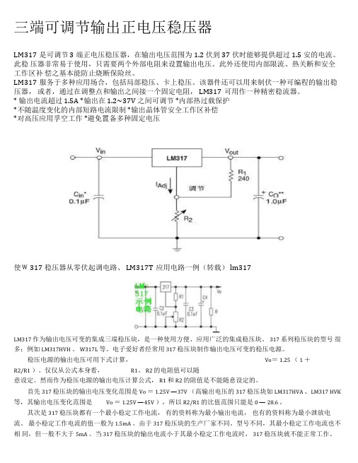
* 输出电流超过1.5A *输出在1.2~37V 之间可调节*内部热过载保护*不随温度变化的内部短路电流限制*输出晶体管安全工作区补偿*对高压应用孚空工作*避免置备多种固定电压使W317 稳压器从零伏起调电路、LM317T应用电路一例(转载)lm317LM317 作为输出电压可变的集成三端稳压块,是一种使用方便、应用广泛的集成稳压块。
317 系列稳压块的型号很多:例如LM317HVH 、W317L 等。
电子爱好者经常用317 稳压块制作输出电压可变的稳压电源。
稳压电源的输出电压可用下式计算,Vo=1.25 (1 +R2/R1 )。
仅仅从公式本身看,R1、R2 的电阻值可以随意设定。
然而作为稳压电源的输出电压计算公式,R1 和R2 的阻值是不能随意设定的。
首先317 稳压块的输出电压变化范围是Vo =1.25V —37V (高输出电压的317 稳压块如LM317HVA 、LM317 HVK 等,其输出电压变化范围是Vo =1.25V —45V ),所以R2/R1 的比值范围只能是0 —28.6 。
其次是317 稳压块都有一个最小稳定工作电流,有的资料称为最小输出电流,也有的资料称为最小泄放电流。
最小稳定工作电流的值一般为1.5mA 。
由于317 稳压块的生产厂家不同、型号不同,其最小稳定工作电流也不相同,但一般不大于5mA 。
当317 稳压块的输出电流小于其最小稳定工作电流时,317 稳压块就不能正常工作。
LM317LDR2中文资料
4
RR
dB
60
80
-
-
80
-
-
-
-
180
-
°C
Long Term Stability, TJ = Thigh (Note 8) TA = 25°C for Endpoint Measurements
3
S
-
0.3
1.0
%/1.0 k
Hrs.
3. Tlow to Thigh = 0° to +125°C for LM317L -40° to +125°C for LM317LB, NCV317LB 4. Imax = 100 mAąąPmax = 625 mW 5. Load and line regulation are specified at constant junction temperature. Changes in VO due to heating effects must be taken into account
1
Regline
-
0.02
0.07
%/V
Load Regulation (Note 5)
ą10 mA ≤ IO ≤ Imax - LM317L ąąVO ≤ 5.0 V ąąVO ≥ 5.0 V
2
Regload
-
20
70
mV
0.3
1.5
% VO
Temperature Stability (Tlow ≤ TJ ≤ Thigh)
Vin
300
300
300
3.0k 300
70
GCLM317L中文资料
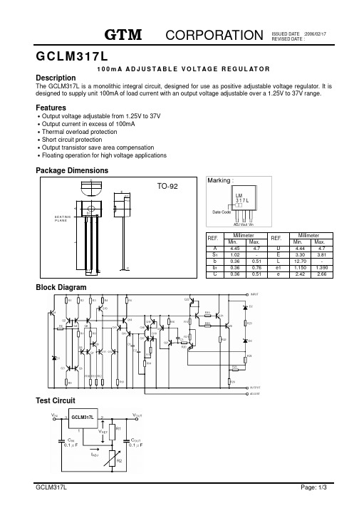
GCLM317L100m A A D J U S T A B L E V O L T A G E R E G U L AT O RDescriptionThe GCLM317L is a monolithic integral circuit, designed for use as positive adjustable voltage regulator. It is designed to supply unit 100mA of load current with an output voltage adjustable over a 1.25V to 37V range. FeaturesOutput voltage adjustable from 1.25V to 37VOutput current in excess of 100mAThermal overload protectionShort circuit protectionOutput transistor save area compensationFloating operation for high voltage applicationsBlock DiagramTest CircuitGCLM317LAbsolute Maximum Ratings at Ta = 25ParameterSymbol Ratings Unit Input-Output Voltage Difference V IN - V OUT40 V Power Dissipation P D 625 mW Junction TemperatureT J +125 Operating Junction Temperature T OPR 0 ~ +70 Storage Temperature RangeT STR-40 ~ +150Note 1. Absolute maximum ratings are those values beyond witch the device could be permanently damaged. Absolute maximum ratings are stress ratings only and functional device operation is not implied.2. The device is guaranteed to meet performance specification within 0 ~ 70 operating temperature range and assured by design from -20Electrical Characteristics(V IN - V OUT =5V, 0 T J 125, I O =40mA, unless otherwise specified)ParameterSymbol Test ConditionsMin TYP Max Unit T J =25 - 0.01 0.04 %/V Line RegulationREG LINEV IN -V OUT =3~40V I O <20mA 0 T J 125- 0.02 0.07 %/V T J =25 - 5 25 I O =5~100mA V OUT 5V 0 T J 125- 20 70 mVT J =25 - 0.1 0.5 Load Regulation REG LOADI O =5~100mA V OUT 5V0 T J 125- 0.3 1.5 %/V OUTAdjustable Pin Current I ADJ- 50 100 A Adjustable Pin Current Change I ADJ V IN -V OUT =3~40VI O =5~100mA, P D < 625mW - 0.2 5 A Reference VoltageV REF V IN -V OUT =3~40VI O =5~100mA, P D < 625mW1.2 1.25 1.3 V Output Voltage Temperature Stability V OUT /V OUT- 0.7 - % Minimum Load Current I LOAD(Min) V IN -V OUT =40V - 3.5 5 mA V IN -V OUT =3~13V 100 200 Maximum Output Current I OUT(Max) V IN -V OUT =40V25 50 - mAOutput Noise Voltage (% of V OUT ) eN f=10Hz ~ 10KHz, T J =25 - 0.003 - %/V OUTC ADJ =0 - 65 - Ripple RejectionRRT J =25 , f=120HzC ADJ =10uF6680-dBNote: C ADJ is connected between Adjust pin and Ground.Characteristics CurveApplication Information and CircuitsThe GCLM317L provides an internal reference voltage of 1.25V between the output and adjustments terminals. This is used to set a constant current flow across an external resistor driver, giving an output voltage V OU T of: V OUT = V REF * (1 + R2 / R1) + I ADJ * R2The device is designed to minimize the term I ADJ (100uA max) and to maintain it very constant with line and load charges. Usually, the error term I ADJ *R2 can be neglected. To obtain the previous requirement, all the regulator quiescent current is returned to the output terminal, imposing a minimum load current condition. If the load is insufficient, the output voltage will rise. The GCLM317L is a floating regulator, input-output differential voltage, supplies of very high voltage with respect to ground can be regulated as long as the maximum input-output differential is not exceeded. Furthermore, programmable regulators are easily obtainable and, by connecting a fixed resistor between the adjustment and output, the device can be used as a precision current regulator.Fig 1. Basic Adjustable RegulatorFig 2. Voltage Regulator withProtection DiodesFig 3. Slow Turn-On 15V RegulatorFig 4. 5V Electronic Shut-Down RegulatorGCLM317L GCLM317LGCLM317LGCLM317L。
ISL3179EIBZ-T中文资料
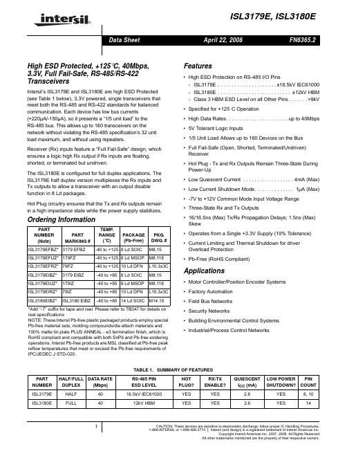
The ISL3180E is configured for full duplex applications. The ISL3179E half duplex version multiplexes the Rx inputs and Tx outputs to allow a transceiver with an output disable function in 8 Ld packages.
PART NUMBER
ISL3179E
ISL3180E
HALF/FULL DATA RATE
DUPLEX
(Mbps)
HALF
40
FULL
40
TABLE 1. SUMMARY OF FEATURES
RS-485 PIN ESD LEVEL
HOT PLUG?
RX/TX ENABLE?
16.5kV IEC61000
Applications
• Motor Controller/Position Encoder Systems • Factory Automation • Field Bus Networks • Security Networks • Building Environmental Control Systems • Industrial/Process Control Networks
NOTE: *Shutdown Mode
Truth Table
RECEIVING
INPUTS
RE
DE
A-B
0
0
≥ -0.05V
0
0
≤ -0.2V
0
0
Inputs Open/Shorted
78XX系列稳压器资料

78系列三端固定正输出稳压器这类稳压器的输出为固定电压。
国内外各生产厂家均将此系列稳压器命名为78x x系列,如7805、7812等。
其中‘78’后面的数字代表该稳压器输出的正电压数值,以伏特为单位。
例如7805即表示7812表示稳压输出12V等。
有时我们会发现型号78xx前面和后面还有一个或几个英文字母,如:W78xx、AN78xx、L78xxCV等。
前面的字母称“前缀”一般是各生产厂(公司)的代号,后面的字母称‚后缀‛,用以表示输出电压容差和封装外各生厂家对集成稳压器型号后缀所用字母定义不一,但这对实际使用没多大的影响。
78xx系列稳压器按输出电压分,共有9种。
分别为:7805、7806、7809、7810、7812、7815、7818、7824。
按其最大输出又可分为:78L x x、78Mxx和78xx 三个分系列。
78Lxx系列最大输出电流为100mA;78M为500mA;78xx系列最大输出电流为1〃5A。
78xx系列稳压器外形见图。
其中,78Lxx系列有两种封装形式。
一种是金属壳的TO-39封装,见图(a);一种是塑料TO-92封装,见图(b)。
前者温度特性比后者好,最大功耗为700mW,加散热片最大功耗可达1〃4W。
后者功耗为700mW,使用时无需加散热片。
78Lxx系列中,一般以塑封的使用较多78Mxx系列有两种封装形式。
一种是TO-202塑封,见图(c)。
不加散热片时最大功耗为1W,加200×200×40m㎡散热片时最大功耗可达7〃5W。
78xx系列也有两种封装形式:一种是金属壳的TO-3封装,见图(e);另一种是塑料TO-220封装,见图(d)。
不加散热片时,前者最大功耗可达2.5W,后者可达2W;加装200×200×40m㎡散热片时,最大功耗可达15W。
如7805、7812等。
即表示稳压输出为5V。
、L78xxCV等。
前面的字母称“前缀”,封装外壳的类型等。
L78M05CDT-TR中文资料
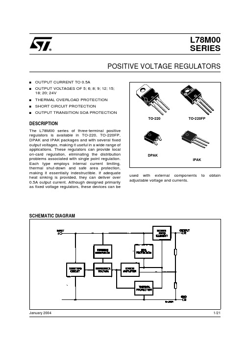
Symbol VO VO ∆VO ∆VO Id ∆Id Parameter Output Voltage Output Voltage Line Regulation Load Regulation Quiescent Current Quiescent Current Change IO = 5 to 350 mA IO = 200 mA ∆VO/∆T Output Voltage Drift SVR eN Vd Isc Supply Voltage Rejection Output Noise Voltage Dropout Voltage Short Circuit Current IO = 5 mA VI = 10.5 to 25 V TJ = 0 to 125°C 56 52 2 250 -0.5 IO = 5 to 350 mA VI = 10.5 to 25 V VI = 11 to 25 V IO = 5 to 500 mA IO = 5 to 200 mA VI = 10.5 to 23 V IO = 200 mA IO = 200 mA TJ = 25°C TJ = 25°C Test Conditions Min. 7.7 7.6 Typ. 8 8 Max. 8.3 8.4 100 50 160 80 6 0.5 0.8 mV/°C dB µV V mA mA mA mV Unit V V mVRIES
杰威尔电子67-21SYGC S530-XX TR8 TOP视角LED技术数据表说明书

Everlight Electronics Co., Ltd. Device No. : DSE-671-159
prepared date: 07-29-2005
Rev. 3 Page: 4 of 9
Prepared by: Teresa
EVERLIGHT ELECTRONICS CO.,LTD.
Everlight Electronics Co., Ltd. Device No. : DSE-671-159
prepared date: 07-29-2005
Rev. 3 Page: 2 of 9
Prepared by: Teresa
EVERLIGHT ELECTRONICS CO.,LTD.
EVERLIGHT ELECTRONICS CO.,LTD.
Technical Data Sheet
TOP View LEDs
67-21SYGC/S530-XX/TR8
Features
․P-LCC-2 package.
․White package. ․Optical indicator. ․Colorless clear window. ․Wide viewing angle. ․Suitable for vapor-phase reflow, Infrared reflow
Tsol
Electro-Optical Characteristics (Ta=25℃)
Parameter
Symbol
*Chip Rank
Min.
E1
16
E2
25
Luminous Intensity
IV
E3
32
E4
TRS-7250G中文资料
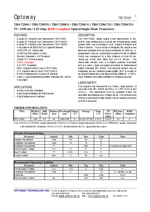
Optoway TRS-7250G**********************************************************************************************************************************************************************************************************************************************************************************************************************************************OPTOWAY TECHNOLOGY INC. No .38, Kuang Fu S. Road, Hu Kou, Hsin Chu Industrial Park, Hsin Chu, Taiwan 3031TRS-7250G / TRS-7250TG / TRS-7250FG / TRS-7250CG / TRS-7250CTG / TRS-7250CFG 5V / 1550 nm / 1.25 Gbps RoHS Compliant Optical Single-Mode Transceiver**********************************************************************************************************************************************************************FEATURESl Duplex SC Single Mode Transceiver: TRS-7250G l Duplex ST Single Mode Transceiver: TRS-7250TG l Duplex FC Single Mode Transceiver: TRS-7250FG l Compliant with IEEE-802.3z Gigabit Ethernet l 1550 DFB LD Transmitter l 19 dB Power Budget At Least l Industry Standard 1 x 9 Footprint l Single +5 V Power Supply l RoHS Compliant l 0 to 70o C Operatingl PECL Signal Detect Output: TRS-7250G l TTL Signal Detect Output: TRS-7250CG l Wave Solderable and Aqueous Washablel Class 1 Laser International Safety Standard IEC 60825 CompliantAPPLICATIONSl Switch to Switch Interfacel High Speed Interface for File Servers l High Performance DesktopsDESCRIPTIONThe TRS-7250G series single mode transceivers is low power, high performance module for bi-directional serial optical data communications such Gigabit Ethernet and Fibre Channel. This module is designed for single mode fiber and operates at a nominal wavelength of 1550 nm. A guaranteed minimum optical link budget of 19 dB is offered which can correspond to a link distance of over 50 km (assuming worst case fiber loss of 0.3 dB/km). The transmitter section uses a multiple quantum well laser and is a class 1 laser compliant according to International Safety Standard IEC 60825. The receiver section uses an integrated InGaAs detector preamplifier (IDP) mounted in an optical header and a limiting post-amplifier IC. A PECL logic interface simplifies interface to external circuitry.LASER SAFETYThis single mode transceiver is a Class 1 laser product. It complies with IEC 60825 and FDA 21 CFR 1040.10 and 1040.11. The transceiver must be operated within the specified temperature and voltage limits. The optical ports of the module shall be terminated with an optical connector or with a dust plug.ORDER INFORMATIONP/No. Bit Rate (Mb/s) 1000BASE Distance (km) Wavelength (nm) Voltage(V)PackageTemp. (o C)TX Power (dBm) RX Sens. (dBm) RoHS Compliant TRS-7250G1250XD501550 DFB51X9 SC/ST/FC 0 to 700 to -5 -24 YNote: TRS-XXXXX F for FC duplex transceiver, TRS-XXXXX T for ST duplex transceiver, TRS-XXXXX-EM for SC duplex transceiverwith extended EMI shielding, TRS-XXXXX C X for transceiver with TTL signal detection output.Absolute Maximum RatingsParameterSymbol Min Max Units NotesStorage Temperature Tstg -40 85 o C Operating Temperature Topr -5 70 o CSoldering Temperature --- 260 o C 10 seconds on leads only Power Supply Voltage Vcc 0 6 V Input Voltage --- GND Vcc V Output CurrentIout30mARecommended Operating ConditionsParameterSymbol Min Typ Max Units Power Supply Voltage Vcc 4.75 5 5.25 VOperating Temperature Topr 0 70 oC / air flow 1m/secData Rate1250 1300 Mb/s Power Supply CurrentIcc180280mA***********************************************************************************************************************************************************************OPTOWAY TECHNOLOGY INC. No .38, Kuang Fu S. Road, Hu Kou, Hsin Chu Industrial Park, Hsin Chu, Taiwan 303Transmitter Specifications (0o C < Topr < 70o C, 4.75V < Vcc < 5.25V)ParameterSymbolMinTyp Max Units Notes OpticalOptical Transmit Power Po -5--- 0 dBm 1Output Center Wavelength λ1480 1580 nmOutput Spectrum Width∆λ--- --- 1 nm -20 dB Width Side Mode Suppression Ratio SMSR 30 dB Extinction Ratio E R 9--- --- dBOutput EyeCompliant with IEEE 802.3zOptical Rise Time t r 0.26 ns 20% to 80% Values Optical Fall Timet f 0.26 ns 20% to 80% Values Relative Intensity Noise RIN -120 dB/HzTotal Jitter TJ0.227 ns 2 ElectricalData Input Current – Low I IL -350 µA Data Input Current – High I IH 350 µA Differential Input Voltage V IH - V IL 300 mVData Input Voltage – Low V IL - V CC -2.0 -1.58 V 3 Data Input Voltage -- HighV IH - V CC-1.1-0.74V3Notes: 1. Output power is power coupled into a 9/125 µm single mode fiber.2. Measured with a 27-1 PRBS.3. These inputs are compatible with 10K, 10KH and 100K ECL and LVPECL inputs.Receiver Specifications (0o C < Topr < 70o C, 4.75 V < Vcc < 5.25V)ParameterSymbol Min Typ Max Units Notes Optical Sensitivity--- --- --- -24 dBm 1Maximum Input Power Pin -3 --- dBmSignal Detect -- Asserted Pa --- --- -24 dBm Transition: low to high Signal Detect -- Deasserted Pd -40 --- --- dBm Transition: high to low Signal detect -- Hysteresis 1.0 --- dBWavelength of Operation 1100 --- 1600 nmElectricalData Output Voltage – Low V OL - V CC -2.0 -1.58 V 2 Data Output Voltage – HighV OH - V CC -1.1 -0.74 V 2Signal Detect Output Voltage -- Low V OL - V CC -2.0 -1.58 V Signal Detect Output Voltage -- High V OH - V CC -1.1 -0.74 V TRS-7250G Signal Detect Output Voltage -- Low V SDL 0.5 V Signal Detect Output Voltage -- HighV SDH2.0VTRS-7250CGNotes: 1. Minimum sensitivity and saturation levels at BER=1E-12 for a 27-1 PRBS.2. These outputs are compatible with 10K, 10KH and 100K ECL and PECL outputs.CONNECTION DIAGRAMReceiver Signal Ground 1 (Rx GND)Receiver Data Out 2 (RD+) N/CReceiver Data Out Bar 3 (RD−)Signal Detect 4 (SD)Receiver Power Supply 5 (Rx Vcc) TOP VIEWTransmitter Power Supply 6 (Tx Vcc)Transmitter Data In Bar 7 (TD−)Transmitter Data In 8 (TD+) N/C Transmitter Signal Ground 9 (Tx GND)PACKAGE DIAGRAMUnits in mm*********************************************************************************************************************************************************************** OPTOWAY TECHNOLOGY INC. No.38, Kuang Fu S. Road, Hu Kou, Hsin Chu Industrial Park, Hsin Chu, Taiwan 303*********************************************************************************************************************************************************************** OPTOWAY TECHNOLOGY INC. No.38, Kuang Fu S. Road, Hu Kou, Hsin Chu Industrial Park, Hsin Chu, Taiwan 303。
sujuwclm317可调稳压管(中文资料)
-+
懒惰是很奇怪的东西,它使你以为那是安逸,是休息,是福气;但实际上它所给你的是无聊,是倦怠,是消沉;它剥夺你对前途的希望,割断你和别人之间的友情,使你心胸日渐狭窄,对人生也越来越怀疑。
—罗兰
lm317中文资料|lm317应用电路图|LM317 pdf内容介绍:包含了LM317的各种应用电路图资料,LM317的工作原理资料,LM317的中文PDF资料,LM317的英文PDF资料,LM317的引脚(管脚)图.
LM317工作原理:LM317的输入最同电压为30多伏,输出电压1.5----32V...电流1.5A...不过在用的时候要注意功耗问题...注意散热问题。
LM317有三个引脚.一个输入一个输出一个电压调节。
输入引脚输入正电压,输出引脚接负载, 电压调节引脚一个引脚接电阻(200左右)在输出引脚,另一个接可调电阻(几K)接于地.输入和输出引脚对地要接滤波电容.
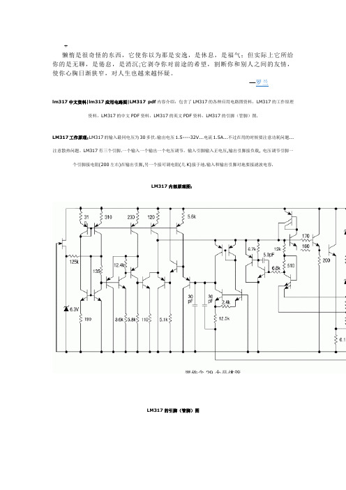
LM317内部原理图:
LM317的引脚(管脚)图
LM317应用电路图:
1.LM317标准应用电路图
2.LM317带可调限流和输出电压的标准应用电路图
3. LM317的5.0V电子关断稳压器应用电路图
4.LM317电流稳压器应用电路图
5.LM317可调节电流限流器的应用电路图
6. LM317软启动应用电路图。
三星公变监测计量终端技术说明书汇总

公变监测计量终端技术说明书编制:_____审核:_____批准:_____宁波三星电气股份有限公司2010年1月10日目录一概述 (2)二前期培训准备 (3)2.1 电能计量功能 (3)2.2 采集功能 (3)2.3低压居民抄表功能 (3)2.4抄表功能 (4)2.5储存功能 (4)2.6异事件报警和记录 (5)2.7 无功补偿控制 (5)2.8对时功能 (5)三液晶显示及菜单指南 (6)3.1液晶显示 (6)3.2显示及菜单项说明………………………………………………………………………………………………………………………错误!未定义书签。
3.3按键操作………………………………………………………………………………………………………………………………………错误!未定义书签。
3.4GPRS信道指示灯说明 (8)四安装说明 (9)4.1 接线端子说明 (9)4.2 连接RS-485通信线 (10)4.3 安装注意事项 (11)五调试步骤 (12)六故障分析与排除 (13)6.1 掉线的分析排除 (13)6.2 无法抄读表计数据的分析排除 (14)一概述公变监测计量终端GKGD42-129 是集多功能电能表、专变检测终端和集中器为一体的新型终端。
该系统通过对城网或农网低压(10KV/380V)配电变压器和下面的居民用户电表进行实时监测和数据采集,及时处理,降低线路线损,为电量分析、线损分析、谐波分析、负载分析、电流不平衡分析、电压合格率统计等功能提供基础数据并对线损过大情况进行主动上报;通过载波方式对用户进行冻结电量抄读、实时召测、远程拉合闸可实现预付费、日线损超值告警、重点用户整点监控终端用户表的自动管理增加服务和响应能力、实现多种计价方案,引导消费,实现错峰填谷,减少峰谷差量等。
公变变终端系统架构示意图如下所示:工作原理简述:终端自身包含计量模块,通讯模块,载波模块,存储模块,功能模块等组成部分,终端将它本身计量的数据和终端通过485通讯方式采集回来的考核表数据(此数据终端每隔5分钟抄收一次)存储到终端的存储模块中,当等到主动上报时间的时候或者遇到远程操控主站发出命令要抄收终端和表计数据的时候,终端通过GPRS无线网络将数据传回主站。
- 1、下载文档前请自行甄别文档内容的完整性,平台不提供额外的编辑、内容补充、找答案等附加服务。
- 2、"仅部分预览"的文档,不可在线预览部分如存在完整性等问题,可反馈申请退款(可完整预览的文档不适用该条件!)。
- 3、如文档侵犯您的权益,请联系客服反馈,我们会尽快为您处理(人工客服工作时间:9:00-18:30)。
100mA Adustable Positive Voltage RegulatorGeneral Description• The LA317L is an adjustable 3-terminal positive voltage regulator capable of supplying 100mA over a 1.2V to 12V output range. This voltage regulator is exceptionally easy to use and requires only tow external resistors to set the output voltage.• The LA317L is available in standard TO-92 and SOP-8 packages.Features Applications• Adjustable output down to 1.2V • Guaranteed 100mA output current • Output short circuit protected • Line regulation: 0.01%/V • Load regulation: 0.1%• Constant current limit over temperature • Standard 3-lead transistor package • Input ripple rejection: 70dB • RoHS ComplianceOrdering InformationTO-92 SOP-8• High Efficiency Linear Regulators• Post Regulation for Switching Supplies • Microprocessor Power Supply • Mother Board I/O Power SupplyLA317LPin ConfigurationBlock DiagramOutline: Z TO-92 Outline: S8 SOP-8LA317LAbsolute Maximum Ratings (Ta=25° C, unless otherwise specified)Symbol DescriptionRatings Unit V IN-V OUT Input - Output Voltage Differential40 V I O Max. Output Current 100 mA T J Operating Junction Temperature 150 ° C T OPR Operating Temperature Range -20 ~ 85 ° C T STG Storage Temperature Range-65 ~ 150 ° C P D Power Dissipation700 mW T LEADLead Temperature (Soldering, 4sec.)260° CElectrical Characteristics(V IN -V OUT =5V, I OUT =40mA,P D ≤625mW, 0ºC ≤T J ≤125ºC, unless otherwise specified)LA317LSymbol Description Min.Typ.Max.Unit Conditions- 0.01 0.04T J =25°, 3V ≤V IN -V OUT ≤15V,I OUT ≤20mA (Note) ∆V OUT/V OUT Line Regulation- 0.02 0.07%/V3V ≤V IN -V OUT ≤15V, I OUT ≤20mA(Note)- 0.1 0.5 % T J =25°, 5mA ≤I OUT ≤100mA (Note) ∆V OUT Load Regulation - 0.3 1.5 % 5mA ≤I OUT ≤101mA (Note)Thermal Regulation 0.04 0.2 %/W T J =25°, 10ms PulseI ADJ Adjustable Pin Current - 50 100 µA -∆I ADJ Adjustable Pin Current Change - 0.2 5 µA 3V ≤V IN -V OUT ≤15V,5mA ≤I OUT ≤100mAV REF Reference Input Voltage 1.20 1.25 1.30 V 3V ≤V IN -V OUT ≤15V, 5mA ≤I OUT ≤100mA I LIMIT Current Limit100200300mA3V ≤V IN -V OUT ≤13V I L(MIN ) Minimum Load Current forRegulation - 3.5 5 mA 3V ≤V IN -V OUT ≤13V- 62 -V OUT =10V, f=120Hz, C ADJ =0µF PSRR Ripple Rejection60 70 - dBV OUT =10V, f=120Hz, C ADJ =10µF-Temperature Stability- 0.65 - %0° C ≤T J ≤125° CLA317LFig.1- Load Regulation vs. TemperatureTemperature (°C)Fig.3- Reference Voltage vs. Temperature Temperature (° C)Fig.2- Output Voltage vs. Input VoltageInput Voltage (V)LA317LSymbolDescriptionMin.Typ.Max.Unit Conditions - Long Term Stability- 0.3 -%T J =125° C, 1000 Hours- RMS Output Noise (% of V OUT ) - 0.003 - % T J =125° C, 10Hz ≤f ≤10KHz - 185 - TO-92 -Thermal Resistance Junction toCase- 175 -° C/WSOP-8Note: Regulation is measured at constant junction temperature, using pulse testing with a low duty cycle.Changes in output voltage due to heating effects are covered under the specification of thermal regulation.Typical Characteristics CurvesO u t p u t V o l t a g e D e v i a t i o n (V )Fig.4- Adjust Pin Current vs. TemperatureTemperature (° C)O u t p u t V o l t a g e (V )R e f e r e n c e V o l t a g e (V )A d j u s t P i n C u r r e n t (μA )LA317LFig.5- Dropout Voltage vs. TemperatureTemperature (° C)Fig.6- Minimum Operating CurrentInput-Output Differential (V) Fig.7- Ripple Rejection vs. Output VoltageOutput Voltage (V)Fig.8- Ripple Rejection vs. FrequencyFrequency (Hz) Typical Characteristics Curves (Continued)Input-OutputDifferential(V)QuiescentCurrent(mA)RippleRejection(dB)RippleRejection(dB)LA317LFig.9- Load Transient Response(Conditions: V IN =10.25V, V OUT =5.25V, C IN =0.1μF,C OUT =1μF, T A =25℃)Time (200μs/Div) Fig.10- Line Transient Response(Conditions: V IN =10.25 to 11.25V, I OUT =40mA, V OUT =5.25V, C IN =0.1μF, C OUT =1μF, T A =25℃)Time (200μs/Div)Typical Characteristics Curves (Continued)Typical ApplicationΔV O U T (200m V /D i v )I O U T (50m A /D i v )ΔV O U T (200m V /D i v )ΔV I N (0.5V /D i v )Fig.11- 5V Logic Regulator with Electronic Shutdown (Minimum output=1.2V) Fig.12- Adjustable Regulator with Improved Ripple RejectionNote: Discharge C1 if output is shorted to groundLA317L Typical Application (Continued)Fig.13- Slow Turn-on 15V RegulatorDimensions in mm (inches)TO-92LA317L Dimensions in mm (inches) (Continued)SOP-8LA317L How to contact us:。
