Q-sys广播、音频系统介绍
Q-SYS NS Series Gen 2 网络交换机快速入门指南说明书
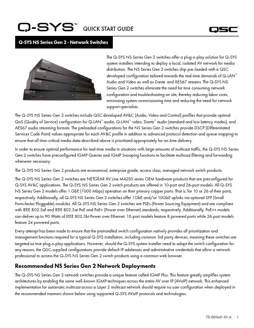
QUICK START GUIDE®The Q-SYS NS Series Gen 2 switches offer a plug-n-play solution for Q-SYSsystem installers intending to deploy a local, isolated AV network for mediadistribution. The NS Series Gen 2 switches ship pre-loaded with a QSCdeveloped configuration tailored towards the real-time demands of Q-LAN™Audio and Video as well as Dante and AES67 streams. The Q-SYS NSSeries Gen 2 switches eliminate the need for time consuming networkconfiguration and troubleshooting on site, thereby reducing labor costs,minimizing system commissioning time and reducing the need for networksupport specialists.The Q-SYS NS Series Gen 2 switches include QSC developed AV&C (Audio, Video and Control) profiles that provide optimal QoS (Quality of Service) configuration for Q-LAN™ audio, Q-LAN™ video, Dante™ audio (standard and low latency modes), and AES67 audio streaming formats. The preloaded configurations for the NS Series Gen 2 switches provide DSCP (Differentiated Services Code Point) values appropriate for each AV&C profile in addition to advanced protocol detection and queue mapping to ensure that all time-critical media data described above is prioritized appropriately for on-time delivery.In order to ensure optimal performance for real-time media in situations with large amounts of multicast traffic, the Q-SYS NS Series Gen 2 switches have preconfigured IGMP Querier and IGMP Snooping functions to facilitate multicast filtering and forwarding whenever necessary.The Q-SYS NS Series Gen 2 products are economical, enterprise grade, access class, managed network switch products.The Q-SYS NS Series Gen 2 switches are NETGEAR AV Line M4250 series OEM hardware products that are preconfigured forQ-SYS AV&C applications. The Q-SYS NS Series Gen 2 switch products are offered in 10-port and 26-port models. All Q-SYS NS Series Gen 2 models offer 1 GbE (1000 Mbps) operation on their primary copper ports. That is, for 10 or 26 of their ports, respectively. Additionally, all Q-SYS NS Series Gen 2 switches offer 1GbE and/or 10GbE uplinks via optional SFP (SmallForm-factor Pluggable) modules. All Q-SYS NS Series Gen 2 switches are PSEs (Power Sourcing Equipment) and are compliant with IEEE 802.3af and IEEE 802.3at PoE and PoE+ (Power over Ethernet) standards, respectively. Additionally, PoE++ models can deliver up to 90 Watts of IEEE 802.3bt Power over Ethernet. 10-port models feature 8 powered ports while 26-port models feature 24 powered ports.Every attempt has been made to ensure that the preinstalled switch configuration natively provides all prioritization and management functions required for a typical Q-SYS installation, including common 3rd party devices, meaning these switches are targeted as true plug-n-play applications. However, should the Q-SYS system installer need to adapt the switch configuration for any reason, the QSC-supplied configurations provide default IP addresses and administrative credentials that allow a network professional to access the Q-SYS NS Series Gen 2 switch products using a common web browser.Recommended NS Series Gen 2 Network DeploymentsThe Q-SYS NS Series Gen 2 network switches provide a unique feature called IGMP Plus. This feature greatly simplifies system architectures by enabling the same well-known IGMP techniques across the entire AV over IP (AVoIP) network. This enhanced implementation for automatic multicast across a Layer 2 multicast network should require no user configuration when deployed in the recommended manners shown below using supported Q-SYS AVoIP protocols and technologies.Example A: Completely Isolated SystemsIn this scenario, individual Q-SYS systems within a facility are completely isolated islands with their own dedicated networks and no interaction with, or connection to, other systems or the facility’s infrastructure and services.This scenario will work completely turnkey with no adjustments to the switches required.Room 1Room 2Room 3Example B: Completely Isolated Systems with Switch ManagementIn many facilities with existing infrastructure and/or IT staff on hand, they may desire a connection to the AV switches for basic monitoring or management. The Q-SYS NS Series Gen 2 switches feature an OOB (Out of Band) port that can be used for direct access to the switch’s management functions without the need to connect to the AV network(s). This OOB port is configured for DHCP and will fall back to 192.168.0.239 if no DHCP service is available. Note: It may take up to 5 minutes for the OOB port to fall back to its default IP after initial power on or a reboot.Example C: Centralized System Management, Access to Corporate Services and/or InternetThe following is the most common deployment scenario for Q-SYS Systems. In this scenario, the systems are still largely isolated with respect to real-time, multicast, and high-bandwidth AV traffic, but the Core’s LAN B or AUX connections are used to provide centralized management, integration with corporate services such as VoIP, or provide the Cores access to the Internet for remote management and monitoring through Q-SYS Reflect Enterprise Manager. Refer to the Q-SYS Designer Help file for information on configuring the specific services present on a Core’s LAN B or AUX connection.Example D: Integrating Q-SYS SystemsIn some cases, it may be desirable to share content between systems or integrate a facility’s centralized paging and background music distribution. As long as only Q-SYS NS Series Gen 2 switches are interconnected, attention is paid to the bandwidth utilization of ISLs (Inter-Switch Link), and care is taken to avoid IP address conflicts as documented further on, the unique QSC configurations and IGMP Plus features of the Q-SYS NS Series Gen 2 will allow a scenario as shown below.Facility AudioFor applications beyond these scenarios, please consult a qualified AV&C network designer or engineer.DHCP ServerThe Q-SYS NS Series Gen 2 switches have a built-in DHCP server which has also been pre-configured by QSC, but is disabled by default.In Examples A - C above, it may be desirable to enable the DHCP server when not using static addressing within the individualQ-SYS systems. This can make configuring, managing, and servicing the system much easier as any computer plugged into the system’s switch should automatically receive an IP configuration within the scope of the system, thus be able discover and connect to it.When the DHCP server in the Q-SYS NS Series Gen 2 switch is enabled, it will assign devices attached to the switch an IP in the range of 192.168.0.151 - 192.168.0.254.Enabling the DHCP ServerWARNING! If you choose to enable the DHCP Server on an NS Series Gen 2 switch, DO NOT connect it to any other existing network infrastructure or to any other NS Series Gen 2 that also has its DHCP Server enabled!1. Connect your PC to either one of the Gigabit copper ports or the OOB (Out of Band) port.a. If using a Gigabit copper port, configure your PC’s Ethernet interface with a static IP address in the 192.168.0.xscope.b. If using the OOB port, it will default to 192.168.0.239 (when no DHCP server is present) which will also requireconfiguring your PC’s Ethernet interface with a static IP address in the 192.168.0.x scope.Note: It may take up to 5 minutes for the OOB port to fall back to its default IP after initial power on or a reboot.2. Open a web browser and type in the IP address of the switch.3. Select “Main UI Login”.4. Use the default login credentials (if still applicable).5. You will now see the System->Management->System Information screen.6. Select System->Services from the top banner menu.7. Select DHCP Server->DHCP Server Configuration from the left hand menu tree.8. Check the “Enable” radio button under DHCP Server Configuration: Admin Mode.9. Click the “Apply” button in the upper right.10. Click the “SAVE” icon in the upper right.If you wish to use the NS Series Gen 2 switches for DHCP addressing in a scenario similar to Example D, only enable the DHCP Server on a single NS Series Gen 2 switch, preferably the most central switch (the NS26-300+).Default IP Configurations:192.168.0.110, 255.255.255.0 : NS26-300+ (26-port PoE+)192.168.0.111, 255.255.255.0 : NS26-1440++ (26-port PoE++)192.168.0.120, 255.255.255.0 : NS10-125+ (10-port PoE+)192.168.0.121, 255.255.255.0 : NS10-720++ (10-port PoE++)Default Credentials:Username: adminPassword: qscsystemsIMPORTANTDO NOT load any firmware or configuration versions other than those approved by QSC. The firmware version qualified by QSC will not always be the most recent release found on the Netgear website for the M4250 product line.It should be noted that QSC Support can only assist with support inquiries when the NS Series Network Switch is running the original, unedited switch configuration. QSC does not support applications beyond the supplied configurations, such as additional VLANs, other AV&C protocols etc. If necessary, a factory reset operation will return the Q-SYS NS Series to the QSC-provided default configuration.Changing Default IP Configurations or Accommodating Multiple Same-model Switches It may be necessary to change the default IP configuration on one or more Q-SYS NS Series switches to avoid conflicts orto fit your specific topology and network addressing schema. Use the following steps to verify and/or change a switch’s IP configuration:1. Isolate the switch. (Disconnect it from any existing network or other switches.)a. Connect your PC to either one of the Gigabit copper (numbered) ports or the OOB (Out of Band) port.b. If using a Gigabit copper port, configure your PC’s Ethernet interface with a static IP address in the 192.168.0.xscope.2. If using the OOB port, it will default to 192.168.0.239 (when no DHCP server is present) which will also requireconfiguring your PC’s Ethernet interface with a static IP address in the 192.168.0.x scope. Note: It may take up to 5minutes for the OOB port to fall back to its default IP after initial power on or a reboot.3. Open a web browser and type in the IP address of the switch.4. Select “Main UI Login”.5. Use the default login credentials (if still applicable).6. You will now see the System->Management->System Information screen.7. Select Management Interfaces->IPv4 Management VLAN Configuration from the left hand menu tree.8. Adjust the IP Address, Subnet Mask, and Gateway fields as necessary.9. Click the “Apply” button in the upper right. If you’ve changed the IP Address, you will now lose connection to the switchand it will log you off as it changes its IP configuration, however your web browser may not show that anything hashappened.10. Type the new IP address of the switch into your web browser.11. Select “Main UI Login”.12. Use the default login credentials (if still applicable).13. Click the “SAVE” icon in the upper right.Changing Default CredentialsIt may be desirable to change the login credentials for increased security. To change password for the administrator account:1. Connect your PC to either one of the Gigabit copper (numbered) ports or the OOB (Out of Band) port.a. If using a Gigabit copper port, configure your PC’s Ethernet interface with a static IP address in the 192.168.0.xscope.b. If using the OOB port, it will default to 192.168.0.239 (when no DHCP server is present) which will also requireconfiguring your PC’s Ethernet interface with a static IP address in the 192.168.0.x scope. Note: It may take up to 5minutes for the OOB port to fall back to its default IP after initial power on or a reboot.2. Open a web browser and type in the IP address of the switch.3. Select “Main UI Login”.4. Use the default login credentials (if still applicable).5. You will now see the System->Management->System Information screen.6. Select Security->Management Security from the top banner menu.7. Select Local User->User Management from the left hand menu tree.8. Check the “admin” account, change the “Edit Password” drop down from “Disabled” to “Enabled” and enter your newpassword into the “Password” and “Confirm Password” fields.9. Click the “Apply” button in the upper right.10. Click the “SAVE” icon in the upper right.WARNING! If you lose or forget the administrator account credentials, the only course of recovery is a factory reset procedure as documented below!Factory ResetTo restore the Q-SYS NS Series switches to their factory defaults, press and hold the reset switch on the rear for 5 to 10 seconds, then release. After the switch has fully rebooted, it will be as-shipped from QSC, including default IP configurations and default credentials as documented above.For additional information regarding hardware specifications, product configuration or regulatory compliance, visit the Netgear website at: /support.For additional information regarding the Q-SYS NS Series network switches, Q-SYS Designer software, and other products or solutions, visit the QSC website at .Mailing Address:QSC, LLC1675 MacArthur BoulevardCosta Mesa, CA 92626-1468 U.S.Main Number: +1.714.754.6175Sales & Marketing:https:///contact-us/ QSC Technical ServicesQSC Technical Services1675 MacArthur Blvd.Costa Mesa, CA 92626 U.S.Tel: +1.800.772.2834 (U.S. only)Tel: +1.714.957.7150FAX: +1.714.754.6173Q-SYS™ Applications Engineering Team (AET) and Technical Services Group (TSG) Non-Emergency Support:Monday – Friday, 7AM to 5PM PST (excluding holidays)Tel. 1.800.772.2834 (North America)Tel. +1.714.957.7150 (All Other Regions)© 2021 QSC, LLC. All rights reserved.QSC and the QSC logo are registered trademarks of QSC, LLC in the US Patent and Trademark Office and in other countries. Q-SYS and Q-LAN and the Q-SYS logo are trademarks of QSC, LLC. Patents may apply or be pending. DANTE is a trademark of Audinate, LLC. NETGEAR and the NETGEAR logo are trademarks of NETGEAR, Inc. Any other trademarks mentioned or portrayed in this document are for reference purposes only.®。
公共广播及背景音乐系统方案

公共广播及背景音乐系统方案一、项目背景随着我国经济水平的不断提高,人们对生活品质的追求也越来越高。
公共广播及背景音乐系统作为提升场所氛围的重要手段,已经广泛应用于商场、酒店、餐厅、公园等场所。
本项目旨在为用户提供一套集公共广播、背景音乐、紧急广播于一体的智能系统,提升场所的整体品质。
二、系统设计1.公共广播系统公共广播系统主要负责场所内的语音广播,包括天气预报、活动通知、紧急广播等。
系统采用数字信号传输,保证声音清晰、无杂音。
具体设计如下:(1)广播分区:根据场所的实际情况,将广播区域划分为若干个分区,便于针对不同区域进行广播。
(2)音源设备:选用高品质的音源设备,确保音质优美。
(3)广播主机:采用高性能的广播主机,实现语音播报、音乐播放、紧急广播等功能。
2.背景音乐系统背景音乐系统主要负责为场所提供舒适的音乐氛围,具体设计如下:(1)音乐分区:根据场所的布局,将音乐区域划分为若干个分区,实现不同区域播放不同风格的音乐。
(2)音源设备:选用丰富的音源设备,包括CD、硬盘、网络音乐等,满足不同场景的需求。
(3)音乐播放器:采用智能音乐播放器,实现自动切换、定时播放等功能。
3.紧急广播系统紧急广播系统主要用于应对突发事件,如火灾、地震等,具体设计如下:(1)紧急广播分区:与公共广播分区相同,实现紧急广播的全覆盖。
(2)紧急广播主机:采用专用紧急广播主机,实现一键启动、自动切换等功能。
(3)紧急广播话筒:配备专用话筒,确保紧急广播的实时性和准确性。
三、系统安装与调试1.安装(1)布线:根据设计图纸,进行布线施工,确保线路安全、美观。
(2)设备安装:按照设计要求,安装音源设备、广播主机、播放器等。
(3)分区设置:根据实际需求,进行分区设置,确保广播和音乐播放的准确性。
2.调试(1)音质测试:对音源设备、广播主机、播放器等进行音质测试,确保音质优美。
(2)功能测试:对广播系统进行功能测试,包括语音播报、音乐播放、紧急广播等。
酒店公共广播和背景音乐系统方案

对系统的各个功能进行测试,确保每个功 能都能正常工作。
系统性能测试
系统验收
对系统的性能进行测试,包括响应时间、 传输速率等指标,确保系统性能达到预期 要求。
在系统测试通过后,应由酒店方和系统集 成商共同进行验收,确保系统的质量和功 能满足合同要求。
06
售后服务与维护
售后服务承诺与保障
专业服务团队
切换功能
在不同区域或场合,应具备快速切换背景音乐的功能,以满足不同场景的需求。同时,还应具备手动控制功能, 以便于客人或员工进行操作。
04
系统设计与实施
系统架构与布局
分布式架构
酒店公共广播和背景音乐系统采用分 布式架构,由中心机房、传输网络、 末端设备组成。
中心机房
中心机房是系统的核心,包括音源设 备、功率放大器、光端机等设备。
音乐播放
系统应支持播放存储在本地或远 程服务器上的音乐文件,满足客
人的休闲需求。
音乐控制
系统应具备音乐控制功能,可以控 制音乐的播放、暂停、音量等,方 便客人使用。
音乐选择
系统应支持客人选择自己喜欢的音 乐进行播放,提高客人的满意度。
系统整体测试与验收
系统稳定性测试
系统功能测试
在系统正式投入使用前,应对系统的稳定 性进行严格的测试,确保系统在长时间运 行中不会出现故障。
防潮防尘
根据酒店环境,定期清理设备表面灰尘和污垢, 保持设备干燥、清洁。
更换损耗部件
如遇设备部件损耗或损坏,建议及时更换以确保 系统正常运行。
系统升级与拓展说明
系统升级
为满足酒店不断发展的需求,我们将为您提供系统的升级服务,确保系统的性能和功能得到提升。
拓展建议
根据酒店实际情况,为您提供合理的拓展建议,以满足酒店在其他方面的需求。
功率声学 CXD-Q 功放 用户手册说明书

CXD-Q 放大器ႚઅѓCXD4.2Q!ě!ڟᥑᥬᷞ2000 W!Ꮛ፰ݙډCXD4.3Q ě!ڟᥑᥬᷞ4000 W!Ꮛ፰ݙډCXD4.5Q!ě!ڟᥑᥬᷞ8000 W!Ꮛ፰ݙډTD-000438 -05 -A*TD-000438-05*ኡգ៎“警告!”一词 表示有关人身安全的说明。
如果不遵照这些说明,可能会导致人身伤亡。
“小心!”一词 表示有关可能造成设备损坏的说明。
如果不遵照这些说明,可能会导致损坏设备,这种损坏不在质保范围内。
“重要信息!”一词 表示对于成功完成某一步骤至关重要的说明或信息。
“注意”一词用于指示其他有用信息。
三角中的闪电箭头符号是为了警告用户:在产品外壳中存在未绝缘的“危险”电压,在其达到足够电压时有可能会造成人体触电。
等边三角形内感叹号的目的是为了提醒用户注意本手册中存在重要的安全、操作和维护说明。
᧹࠘м៎֘ᷓ;!为了防止火灾或电击,请勿将此设备暴露在雨中或潮湿环境中。
1. 请阅读这些说明。
2. 请保存好这些说明。
3. 请谨记所有警告。
4. 请遵守所有说明。
5. 不要靠近水的地方使用本设备。
6. 清洁设备时只能用干布擦拭。
7. 不要堵塞任何通风口。
遵循厂商的说明进行安装。
8. 不要安装在会产生热量的热源(如散热器、热调节装置、炉子或者其他设备)附近。
9. 为了降低触电的风险,电源线应连接到带有接地保护的电源插座上。
10. 请勿使极化插头或接地插头的安全性失效。
极性插头上有两块金属片,其中一片比另一片宽。
接地插头有两个叶片,还有第三个接地插脚。
较宽的叶片或第三个插脚用于安全目的。
如果提供的插头无法插入您的插座,请向电工咨询,并更换淘汰的插座。
11. 请在您来回走动,或是紧捏住插头将其拔出插座和设备的时候保护好电源线。
12. 只能使用制造商指定的附件/配件。
13. 请在雷雨期间或放置很久不用时拔掉设备插头。
14. 应由合格人员进行维护。
如果本设备损坏,必须进行维修,比如电源线或插头损坏,液体溅到或物体落入设备中,设备遭受雨淋或受潮,不能正常工作,或跌落等情况。
q-sys技术培训文档精品文档
11x
56x 49x
21x
32x
53x
12x
Core 1000
9x
47x 41x
18x
26x
44x
10x
Core 3/4000
17x
92x 81x
35x
52x
86x
20x
16
特色音频插件
Audio Player Acoustic Echo Canceler Ambient Compensator 2-D Panner PA Router Room Combiner RTA
Cisco 300系列
26
Q-LAN中的数据类型
优先级由高到低:
时钟信号数据
46
音频数据
34
控制和监控数据
0
靠DSCP实现优先级管理: 6 bit字符(0-47级),共48级
27
网络传输距离限制
Switch Hop
1-Hop 2-Hop 3-Hop 4-Hop 5-Hop 6-Hop 7-Hop
T+X=0.667ms
网络传输 T ms
Buffer X ms
D/A 0.25ms
模拟音频输出
总延时为:2.5毫秒(固定)
30
Q-Sys系统
31
完美兼容QSC原有产品
32
功放状态监控
33
扬声器回路状态监控
测试音
34
兼容的QSC功放
支持的功放(带DataPort端口): CX系列(固定安装) PL3系列(演出) DCA系列(电影) PL和PL2(停产)
扬声器级联线
Q-SYS NC Series Cameras 2 Hardware User Manual
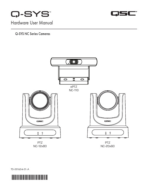
TD-001654-01-A*TD-001654-01*ePTZ NC-110PTZ NC-12x80PTZNC-20x60 Hardware User ManualQ-SYS NC Series CamerasEXPLANATION OF TERMS AND SYMBOLSThe term “WARNING!” indicates instructions regarding personal safety. If the instructions are not followed, the result may be bodily injury or death.The term “CAUTION!” indicates instructions regarding possible damage to physical equipment. If these instructions are not followed, it may result in damage to the equipment that may not be covered under the warranty.The term “IMPORTANT!” indicates instructions or information that are vital to the successful completion of the procedure.The term "NOTE" is used to indicate additional useful information.The intent of the lightning flash with an arrowhead symbol within an equilateral triangle is to alert the user to the presence of un-insulated "dangerous" voltage within the product's enclosure that may be of sufficient magnitude to constitute a risk of electric shock to humans.The intent of the exclamation point within an equilateral triangle is to alert the user to the presence of important safety,operating, and maintenance instructions in this manual.IMPORTANT SAFETY INSTRUCTIONS1. Read these instructions.2. Keep these instructions.3. Heed all warnings.4. Follow all instructions.5. Install in accordance with the manufacturer's instructions.6. Refer all servicing to qualified service personnel.7. Adhere to all applicable local codes.Maintenance and RepairsWARNING!: Advanced technology, e.g., the use of modern materials and powerful electronics, requires specially adapted maintenance and repair methods. To avoid the danger of subsequent damage to the apparatus, injuries to persons, and/or the creation of additional safety hazards, all maintenance or repair work on the apparatus should be performed only by a QSC authorized service station or an authorized QSC International Distributor. QSC is not responsible for any injury, harm, or related damages arising from any failure of the customer, owner, or user of the apparatus to facilitate those repairs. FCC StatementNote: This equipment has been tested and found to comply with the limits for a Class A digital device, pursuant to Part 15 of the FCC Rules.These limits are designed to provide reasonable protection against harmful interference when the equipment is operated in a commercial environment. This equipment generates, uses, and can radiate radio frequency energy and, if not installed and used in accordance with the instruction manual, may cause harmful interference to radio communications. Operation of this equipment in a residential area is likely to cause harmful interference in which case the user will be required to correct the interference at his own expense.Expected Product Life Cycle: 10 years, Storage Temperature range: –-20°C to +60°C, Relative Humidity: range of 5 —85% RH non-condensing.WarrantyFor a copy of the QSC Limited Warranty, visit the QSC, LLC., website at .RoHS StatementThe QSC Q-SYS NC Series: NC-110, NC-12x80, and NC-20x60 are in compliance with European Directive 2015/863/EU – Restriction of Hazardous Substances (RoHS2).What's in the BoxNC-12x80, NC-20x60 PTZ CamerasNC-110 ePTZ CameraIntroductionThe QSC Q-SYS™ NC Series comprises three camera models: NC-12x80, NC-20x60, and NC-110. These cameras send IP streams across a Q-LAN network to certain Q-SYS Core processors and peripherals, which bridge this IP signal to a USB signal for host computers to use in software applications.Connections and Controls (NC-12x80 and NC-20x60 PTZ) Front Panel1. Status LED (Green)• Off indicates the camera is in standby mode; network streams are off.• On indicates the camera is streaming video over the network.• Blinking indicates the ID mode is on.2. Power LED (Blue)• On indicates the camera has power applied.• Off indicates the camera has no power applied.Connections and Controls (NC-12x80 and NC-20x60 PTZ) (continued)Rear Panel56781. Product Label• Identifies product model: NC-12x80 or NC-20x60• Identifies the product serial number • Identifies the product MAC address2. ID Button: Press to identify this product in Q-SYS Designer Software and Q-SYS Configurator. The green STATUS LED on the frontpanel blinks when in ID mode. Press again to turn off.3. Factory Reset pin-hole: Use a paperclip or similarly sized object to insert. Press and hold the reset button for 5 seconds. This resetsall parameters to the factory defaults.4. Kensington™ Lock Slot: for use with a security cable (not supplied).5. DC 12 V: Connect an external power supply (not included). Supply must be rated at 12VDC 1A, EIAJ-04, center pin positive,outside barrel negative. Use only a class 2/LPS power supply.6. LAN/PoE: RJ-45 connector for Q-SYS Gigabit Ethernet and Power over Ethernet. Cat5e cabling or better required.7. 3G-SDI: 3G-SDI output via various video formats. Video formats can be changed via Q-SYS Designer Software or a Q-SYS UserControl Interface (UCI). Maximum video format is 1080p60.8. HDMI: HDMI® 1.4b output via various video formats. Video formats can be changed via Q-SYS Designer Software or a Q-SYSUCI. Maximum video format is 4K30. Note: NC Series PTZ Cameras support the usage of either HDMI or SDI, but not both simultaneously.Installation — NC-12x80 & NC-20x60 PTZInstall the Wall Mount Bracket1. Select a location on the wall or other vertical surface where the camera is tobe mounted. Make sure the surface is strong enough to hold the weight of the camera and bracket.2. Use the short side (1) of the bracket as a template to mark the location of thefour mounting holes (2) onto the wall.3. If the camera cables are installed inside the wall, run the cables through thelarge hole (3) in the short side of the bracket.4. Using appropriate screws (4), as necessary, attach the bracket to the wall.Tighten the attaching hardware. (Screws not supplied.)Bottom plate of Camera Mount the Camera on the Wall Bracket1. Align hole A on the bottom of the camera with the alignment pin A on thewall bracket. Place the camera onto the bracket so the alignment pin isinserted into the alignment hole on the camera and the rubber feet (C) on the bottom of the camera are inserted into the two slots (C).2. Install the larger screw (B) up through the wall bracket into the threaded holeon the bottom of the camera. Use a Phillips screwdriver to loosely tighten the screw.3. Install three smaller screws D, E, and F up through the wall bracket into thebottom of the camera. Tighten the screws using a Phillips screwdriver. 4. Tighten the larger screw installed earlier.5. If the camera cables are not installed in the wall, run the cables up throughthe oval hole (5) in the longer part of the bracket.6. Attach the cables to the appropriate connectors on the back of the cameraper installation requirements.7. Secure the cables to the bracket so that there is no strain placed on theconnectors.Connections and Controls (NC-110 ePTZ)Front Panel1. LED• Blinking Green: ID Mode• Solid Blue: Power On; Not Streaming• Solid Green: Streaming• Off: Camera is in Privacy Mode2. Included Camera Mount: This product can be configured for monitor-mounting or surface-mounting.3. Surface Mounting Screw Holes4. Universal Mounting Adapter: This can be used when connecting the NC-110 to a different mount.Rear Panel1. Factory Reset Pinhole: Use a paperclip or similarly sized object to insert. Press and hold the reset button for 5 seconds. This resetsall parameters to the factory defaults.2. ID Button: Press to identify this product in Q-SYS Designer and Configurator. The STATUS LED on the front panel blinks green whenin ID mode. Press again to turn off.3. LAN/PoE: RJ-45 connector for Q-SYS Gigabit Ethernet and Power over Ethernet. Cat5e cabling or better required.Installation (NC-110 ePTZ)Mounting Above a MonitorBend the bracket at the indicated pivot points shown to allow the optimal fit to the selected monitor. Mounting to a WallUsing the Existing Bracket for a Third-Party Mount1/4-20 UNC ThreadAttach the third-party mount to one of the 1 /4 -20 mounting holes on the included bracket. Removing the Existing Bracket for a Third-Party Mount1. On the bottom side of the camera, remove the two screws on the bracket.Remove 2 x Screws2.Slide the bracket off the camera.3. Mount the camera to the third-party mount.// DO NOT REMOVE \\Screws in block or camera1/4-20 UNC ThreadUse on various camera mounting bracketsInstalling Privacy Cover1. Peel adhesive.2. Center and attach to top of camera.3. Press firmly to affix adhesive.Dimension Drawings NC-12x80 & NC-20x60 PTZPTZ With Lens CapNC-110 ePTZQSC Self Help PortalRead knowledge base articles and discussions, download software and firmware, view product documents and training videos, and create support cases.https:///selfhelpportal/s/Customer SupportRefer to the Contact Us page on the QSC website for Technical Support and Customer Care, including their phone numbers and hours of operation.https:///contact-us/© 2021 QSC, LLC. All rights reserved. QSC, the QSC logo, Q-SYS, and the Q-SYS logo are registered trademarks of QSC, LLC, in the U.S. Patent and Trademark office and other countries. Q-LAN and Q-SYS Designer are trademarks of QSC, LLC. Patents may apply or be pending.All other trademarks are the property of their respective owners.。
QSys系统介绍
QSC新一代网络音频解决方案-Q-Sys系统09年美国QSC公司隆重推出了其新一代网络音频解决方案-Q-Sys系统。
该系统由业内顶尖研发团队耗时3年打造完成,是时下功能最为强大的网络音频系统,一经推出就受到了业内广大人士的关注,成为目前业界热议的话题。
Q - S y s系统是一个完整的系统平台,它可以完成从音源输入一直到音箱输出的整个音频链路的所有功能。
Q-Sys系统可以对所有音频信号进行路由分配,信号处理,对必要的设备进行控制和监测,并保持了高质量的音频信号品质和QSC闻名的可靠性。
Q-Sys 系统专为对音频系统具有很高要求的大型场所设计,是任何需要一套强大的音频处理系统场所的理想选择,比如:体育场、体育馆、主题公园、演艺场所、交通枢纽、政府、多厅法庭、酒店、赌场、教堂、大学校园、教育机构等。
那么,下面我们一起来了解一下Q-Sys系统。
1.Q-Sys系统的架构和设备构成Q-Sys系统是一套基于千兆以太网实时传输无损音频的“集中式处理”的音频系统,其系统构成非常简单:音频处理核心:Core;音频接口箱:I/OFrame以及5款音频输入/输出音频卡。
1.1.系统架构:图1. Q-Sys系统示意图由图中可以看到Q-Sys系统是一套集中式处理,集中和分散相结合式控制管理的一套网络音频系统。
所有的模拟音频信号经音频接口箱进行A/D转换,然后通过千兆网传输至核心Core,进行处理和路由,再通过网络传输回音频接口箱进行D/A转换,输出至功率放大器进行扩声。
在Q-Sys系统网络中,除了音频设备之外,其它控制设备可以与Q-Sys系统共用网络,无需单独划分控制网络VLAN。
1.2.设备构成Core 是整套系统的核心,所有的音频处理、路由控制、设备监控、第三方系统接口以及一些特殊功能应用都是在Core 上完成。
Core 目前具有3个型号:Core1000、Core3000、Core4000;分别可以处理的最大音频通道数量为:64×64、128×128、512×512。
Q-SYS 核心 110 系列硬件用户指南说明书
硬件用户指南Q-SYS 核心 110 系列TD-001541-05-C*TD-001541-05*Core 110fCore 110f v2术语及符号说明“警告!”一词 表示有关人身安全的说明。
如果不遵照这些说明,可能会导致人身伤亡。
“小心!”一词 表示有关可能造成设备损坏的说明。
如果不遵照这些说明,可能会导致设备损坏,这种损坏不在质保范围内。
“重要信息!”一词 表示对于成功完成操作过程至关重要的说明或信息。
“注意”一词用于指示其他有用信息。
三角形内有箭头的闪电状符号可提醒用户,产品外壳内存在未绝缘的“危险”电压,可能对人体构成电击的风险。
等边三角形内有感叹号是为了提醒用户注意本手册中重要的安全、操作和维护说明。
重要安全说明警告!:为了防止火灾或电击危险,请勿将本设备暴露在雨中或潮湿环境中。
环境工作温度升高 — 如果设备安装在封闭式或多单元机架总成中,环境工作温度可能会高于室温。
确保温度不超过设备的最高工作温度范围 0°C 至 50°C(32°F 至 122°F)。
气流减少 — 确保将设备安装在机架中不会影响安全操作所需的气流量。
1. 请阅读这些说明。
2. 请保存好这些说明。
3. 请谨记所有警告。
4. 请遵守所有说明。
5. 请勿在靠近水的区域使用本设备。
6. 请勿将本设备浸入水或其他液体中。
7. 不要使用任何气溶胶喷雾、清洁剂、消毒剂或熏蒸剂清洁本设备及机器内部,请将以上制剂远离本设备。
8. 清洁设备时只能用干布擦拭。
9. 请勿堵塞任何通风口。
遵循制造商的说明进行安装。
10. 保持所有通风口畅通无阻,无灰尘等物质。
11. 请勿将本产品安装在会产生热量的热源附近,如散热器、热调节装置、火炉或其他设备(包括放大器)。
12. 为了降低触电的风险,电源线应连接到带有接地保护的电源插座。
13. 请勿忽视极化或接地插头的安全作用。
极性插头上有两块金属片,其中一片比另一片宽。
公共广播的系统基本知识

音频的基础知识
平衡与非平衡输入
音频输入方面,具有平衡式输入和非平衡式输入 两种方式.
我们普通的莲花头也就是两芯RCA接头属于非 平衡输入方式,只放大+信号,-信号与屏蔽端共用;
而平衡式XLR输入采用的是三芯插头1地2正3 负;+、-信号都是独立放大器,屏蔽端接地;
平衡输出的目的就是为了减少干扰,除非设备不 是平衡输出的就应该使用不平衡输出的接线.所以 接线之前应该注意设备输入、出接口的标识 BALANCE平衡UNBALANCE不平衡
寻人广播或根据现场需要临时向指定的 广播区域发布的广播.
广播的基本概念
寻呼站 独立于广播主机以外的,可以进行分区寻
呼操作的设备.
业务广播 公共广播系统向其服务区域播送的、需
要被全部或部分听众认知的日常广播,包括 发布通知、新闻、信息、语声文件、寻呼等 .
广播的基本概念
消防广播 紧急广播系统平时作为业务广播系统或
音频的基础知识
定压信号和定阻信号的区别
定压信号输出,是由电压来推动扬声器,特点是输 出的电压大、电流小.因此,定压信号传输距离远,扬 声器可以多个并联,但音质比定阻信号稍差. 定阻信号输出,是以电流来推动扬声器,特点是输出的 电流大,电压小.定阻信号传输距离不超过100米,音质、 音效好.
音频的基础知识
额定功率是一种平均功率,而实际上扬声器工作 在变功率状态,它随输入音频信号强弱而变化,在弱音 乐及声音信号中,峰值脉冲信号会超过额定功率很多 倍,由于持续时间较短而不会损坏扬声器,但有可能出 现失真.因此,为保证在峰值脉冲出现时仍能获得很好 的音质,扬声器需留足够的功率余量.一般扬声器能承 受的峰值功率是额定功率的2-3倍
ቤተ መጻሕፍቲ ባይዱ频的基础知识
qscqsys2012
4
5
商用解决方案
机场及交通枢纽
系统总成本(TCO) 无论一个场所的拥有者和运营方是商业组织、中介
代理、教育机构还是非盈利组织,固定安装音频系统 都是对其来说一项重要的投资。然而,音频系统的总 成本不仅仅是购置设备的成本,而是在系统正常寿命 周期内所产生的设备采购、系统运营和系统维护的成 本总和。下面将从几个方面论述Q-Sys系统带给您的 真正价值:
Q-Sys Designer,Q-LAN网络和周边设备组成。 ● Q-Sys Core是整个系统的核心,实现对音频信号的
路由、处理和控制功能。 ● Q-Sys Designer是Q-Sys系统配套的设计、配置和
控制应用软件。 ● Q-LAN是基于标准IP协议的音频传输网络,是整个
Q-Sys系统的基础 ● Q-Sys配套周边产品如 I/O Frame接口箱、输入输
同一个平台,同一个目标 由于QSC旗下产品包含了固定安装音频系统中所
有的设备,因此QSC公司更加了解用户需求,更有可 能开发出适合用户的整体音频解决方案。QSC的售后 支持网络遍布全球,但是QSC的产品研发部门却集中 在一起,为了统一的目标进行工作。包含数字信号处 理、信号路由、信号放大和扬声器在内的所有产品都 是在统一的平台下设计和测试的。其中,Q-Sys硬件 设备和带DataPort的功率放大器甚至是共享QSC公 司南加州总部中的同一条产品线进行生产的。这样的 做法使得QSC各类产品的性能实现完美匹配,用以构 建完整的QSC音频系统而不仅仅是各类产品的简单互 连。Q-Sys系统依然继承了QSC业内闻名的高可靠 性,并且还提供业内顶尖顾问团队的7*24小时的技术 支持,以保证每个Q-Sys系统稳定的运行。因此,选
Q-sys 广播、音频系统 介绍
1.系统设计特点及概述鉴于该系统设计包括多个专业扩声系统,为了达到系统整合的目的,同时又要保证系统稳定性和先进性,这里我们选用QSC公司最新推出的大型网络音频矩阵Q-sys系统为整套系统的核心。
由于Q-Sys系统具有极大的音频处理能力以及通道处理能力,实现Q-Sys 网络音频处理系统最大利用率,达到资源配置最优化。
1.Q-Sys系统介绍Q-Sys系统是美国QSC公司最新研制推出的一套大型网络音频矩阵处理系统。
该系统重新诠释了网络音频系统,具有:非凡的音频处理能力、超强的系统整合能力、磐石般的系统稳定性、简单易懂的可操作性。
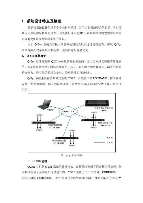
Q-Sys系统主要由音频处理主机CORE、音频接口箱I/O FRAME、控制软件以及千兆网络组成。
所有的设备通过千兆网络连接起来即可完成工作。
如图1所示。
图1. Q-Sys系统示意图CORE主机CORE主机是Q-Sys系统的处理核心,音频系统中所有的音频信号处理、路由和控制信号全部是在这里进行的。
CORE主机分有三个型号:CORE1000、CORE3000、CORE4000。
三种主机分别可以处理64×64、128×128、512*×512*个音频通道,是当今世界上处理能力最强的音频处理主机。
CORE 主机摒弃了传统音频处理主机采用DSP 芯片进行音频信号处理的老方式,而采用全新的音频处理核心-多核64位中央处理单元进行音频信号处理。
采用这种全新的处理引擎后,CORE主机的信号处理能力远远大于传统采用DSP 芯片作为处理核心的音频处理主机。
对比此前处理能力最强的PEA VEY 的NION N6型音频处理主机,最小型的音频处理主机-CORE1000的音频处理能力是NION N6的五倍。
CORE 主机内部内置了多种音频处理模块,如:分频器、混音器、自动混音台、噪声门、路由器、动态处理器、噪声发生器、参量/图示均衡器、动态显示器、音频文件播放器、RTA 测试工具等等,能够满足各类场所音频系统的需要。
广播音响系统

整理ppt
15
音响系统的组成与功能
• 音源设备 • 声音处理设备 • 扩声设备
整理ppt
16
声源设备
• 话筒,又称传声器 ,是声电转换的换能器, 通过声波作用到电声元件上产生电压,再 转为电能。
• (1)立体感 即声音有层次、有方位、有空间感和距离感、 且失真小、动态范围大。
• (2)丰满 即声音厚实、圆润、有足够的响度和亮度、中高 频不缺、低频及中频能量充足,混响声适中,失真小,瞬态 响应好。
• (3)噪声水平 噪声水平低,能提高乐声和语言和清晰度、 扩大声音的动态范围,是保真度的重要指标之一。
面向公众区(如广场、车站、码头、商场、 餐厅、走廊、教室等)和停车场等的公共 广播(PA)系统:这种系统主要用于语言 广播,因此清晰度是首要问题。而且这种 系统往往平时进行背景音乐广播,在出现 灾害或紧急情况时,又可切换成紧急广播。
整理ppt
4
紧急广播
• 面向宾馆客房的广播音响系统:这种系统包括音 响广播和紧急广播,通常由设在客房中的床头柜 放送。客房广播含有收音机的调幅(AM)和调频 (FM)广播波段和宾馆自播的背景音乐等多个可 供自由选择的波段,每个广播均有床头柜扬声器 播放。在紧急广播时,客房广播即自动中断,只 要紧急广播的内容强切传到床头柜扬声器,这时 无论选择器在何位置或关断位置,所有客人均能 听到紧急广播。
整理ppt
5
厅堂扩声系统
• 以礼堂、剧场、体育场馆为代表的厅堂扩声系统: 这是专业性较强的厅堂扩声系统,它不仅摇考虑 电声技术问题,还要涉及建筑声学问题,两者须 统筹兼顾,不可偏废。这类厅堂往往有综合性多 用途的要求,不仅可供会场语言扩声使用,还常 作文艺演出等。对于大型现场演出的音响系统, 电功率少则几万瓦,多则数十万瓦,故要用大功 率的扬声器系统和功率放大器,在系统的配置和 器材选用方面有一定的要求,还应注意电力线路 的负荷问题。
QSC, LLC Q-SYS Core 110f POTS 设计应用指南说明书
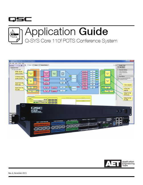
Application GuideQ-SYS Core 110f POTS Conference SystemRev. A, December 20152 QSC, LLC / Q-SYS Core 110f POTS Design Application GuideQ-SYS DESIGNER COMES WITH SAMPLE DESIGNS.Q-SYS Designer 5.0 and higher software automatically installs sample designs. This design is for a conference room utilizing a Core 110f, with eight tabletop mic inputs, two sets of stereo audio inputs, a USB I/O for using a PC as a soft codec for web conferencing, two zones of ceiling loudspeakers, and a POTS (Plain Old Telephone Service) line for voice teleconferencing.This design depicts a thorough set of best practices for developing a Q-SYS system. Use the design as-is, if it fits your needs, or alter it as needed. Or use it as a learning piece to see how Q-SYS components are configured and linked together in a design.Where to find itIn most cases the Q-SYS Designer Installer program will copy it into your Documents folder, but if you have used another version of Designer before and have a different folder for your Q-SYS designs, you might find the file there. Select File > Open , or press Ctrl + O , and select the design file Conf-System-POTS-v[x .x].qsys .The design will look largely like the one in Figure 1. This design could be for a conference room like the one shown in Figure 2.Ins and OutsThe conference room media system design is composed of these inputs and outputs:• 8 tabletop mics•2 pairs of stereo flex ins from stereo media player and Blu-ray player •1 POTS in/out (analog telephone line)•1 USB speakerphone in/out (through PC)•4 line outs (to SPA-60 four-channel amplifier, powering four QSC AC-C6T ceiling loudspeakers)• 2 pairs stereo flex outsThe Core 110f uses pluggable Euro-style connectors for signal inputs and outputs, which are balanced. The connectors are color coded to help installation:• Mic/Line Inputs: orange•Flex Inputs/Outputs: blue •Line Outputs: green •GPIO Inputs and Outputs: black Figure 1.QSC Systems / Q-SYS Core 110f POTS Design Application Guide34 QSC, LLC / Q-SYS Core 110f POTS Design Application GuideConnecting the Mic/Line inputsEach Mic/Line input uses three pins, for + (non-inverting), - (inverting),and ground or shield. Provided with the Core 110f are eight orangethree-pin plugs—one for each input. Connect them to the Core 110f asdepicted in Figure 3. In this design, each input is wired to an individualtabletop mic.Figure 3. Connecting the Mic/Line inputs.Figure 4. Connecting the Flex inputs and outputs.Connecting the Line outputsLike the others, each line output uses three pins, for + (non-inverting),- (inverting), and ground or shield. Provided with the Core 110f areeight green three-pin plugs—one for each output. Connect them to theCore 110 f as depicted in Figure 5.This design uses four line outputs, and in a conference room like theone depicted, they might typically provide audio signal to a poweramplifier that drives the ceiling loudspeakers.Figure 6. The assortment of connections on the Core 110f.Connecting the POTS LineIn this design, the Core 110f connects to a Plain Old Telephone Service (POTS) analog line for teleconferencing. The modular jack on the core’s rear panel connects directly to the phone line via a suitable cable. A User Control Interface (UCI) created for a TSC-7 touchscreen controller contains the phone dialer, volume, and other controls, making them readily accessible on the tabletop. The TSC-7 connects to the core through the local area network (LAN), which is described below.For more information about connecting the Core 110f to a POTS line, see the QSC Technical Note Interfacing POTS with a Conference Room via Core 110f.Connecting the NetworkTwo RJ45 Gigabit Ethernet jacks provide connectivity to the primary LAN, and if required, to a redundant or auxiliary one. The primary network is labeled LAN A and the redundant one is LAN B. LAN B can also be configured as an auxiliary LAN for use on a control or corporate network.The LAN conducts all communication between the core and other network devices, such as any TSC touchscreen controllers. Connecting the USB Type B PortIn this design the Core 110f is configured with one USB endpoint serving as a speakerphone. This feature allows you to operate a teleconferencing session using software such as Skype, GoToMeeting, Lync, Google Hangouts, etc., on the PC connected via the USB port.For more information about using the Core 110f with a PC via USB, see the QSC Technical Note USB Endpoint functions in Core 110f: Soundcard or Speakerphone.QSC Systems / Q-SYS Core 110f POTS Design Application Guide 56 QSC, LLC / Q-SYS Core 110f POTS Design Application GuideFeatures in Q-SYS DesignerChannel GroupA Channel Group (Figure 7) is an efficient and convenient way to drawand apply one or more processing steps simultaneously to two ormore parallel channels of audio.Double click on the Channel Group to open it; we see that in thisdesign it applies high-pass filtering and parametric EQ to each channel(Figure 8).You may configure these eight channels separately, or you mayconfigure some or all them simultaneously; use the selection buttons(1 through 8, plus Prev, Next, Exclusive, Select All, and Select None) tochoose which ones to configure.The high-pass filter and parametric EQ blocks can be opened to allow configuration. The settings you configure will apply to theselected channels.Figure 7.Figure 8.Figure 9. High-pass filter configuration above, and parametric EQ at right.Gating Automatic Mic MixerAs the name suggests, The Gating Automatic Mic Mixer is a multi-channel mixer that has adjustable noise gating on each channel. The one in the default design is configured for eight input channels and one output. It is especially suitable for teleconferencing use because it can take out possibly distracting background noise and improve intelligibility.Figure 10 shows the component opened up for configuration. Like a conventional mixer, it combines multiple audio signals together, but it additionally adds noise gating with a maximum number of open mics, along with adjustable attenuation and threshold parameters. The “Last Mic On” feature leaves the last active mic ungated even when no one is speaking, allowing some background noise to come through and prevent the illusion on the far end that the connection has been lost.Figure 10. The Gating Automatic Mic Mixer.VIDEO TRAINING SERIESAn engaging, self-guided video tutorial series/education/courses/qsysQSC Systems / Q-SYS Core 110f POTS Design Application Guide 7QSC, LLC1675 MacArthur Boulevard Costa Mesa, CA 92626 USA。
Q-Sys系统完全集成解决方案介绍说明书
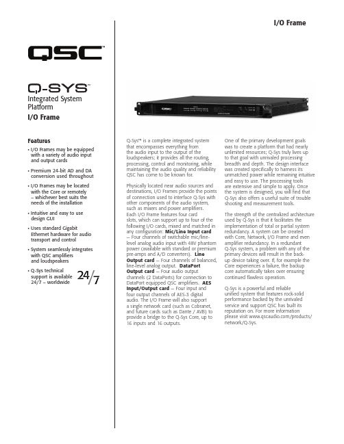
Q-Sys™ is a complete integrated system that encompasses everything from the audio input to the output of the loudspeakers; it provides all the routing, processing, control and monitoring, while maintaining the audio quality and reliability QSC has come to be known for. Physically located near audio sources and destinations, I/O Frames provide the points of connection used to interface Q-Sys with other components of the audio system, such as mixers and power amplifiers. Each I/O Frame features four card slots, which can support up to four of the following I/O cards, mixed and matched in any configuration: Mic/Line Input card — Four channels of switchable mic/line-level analog audio input with 48V phantom power (available with standard or premium pre-amps and A/D converters). Line Output card — Four channels of balanced, line-level analog output. DataPort Output card — Four audio output channels (2 DataPorts) for connection to DataPort equipped QSC amplifiers. AES Input/Output card — Four input and four output channels of AES-3 digital audio. The I/O Frame will also support a single network card (such as Cobranet, and future cards such as Dante / AVB) to provide a bridge to the Q-Sys Core, up to 16 inputs and 16 outputs.One of the primary development goals was to create a platform that had nearly unlimited resources; Q-Sys truly lives up to that goal with unrivaled processing breadth and depth. The design interface was created specifically to harness its unmatched power while remaining intuitive and easy to use. The processing tools are extensive and simple to apply. Once the system is designed, you will find that Q-Sys also offers a useful suite of trouble shooting and measurement tools. The strength of the centralized architecture used by Q-Sys is that it facilitates the implementation of total or partial system redundancy. A system can be created with Core, Network, I/O Frame and even amplifier redundancy. In a redundant Q-Sys system, a problem with any of the primary devices will result in the back-up device taking over. If, for example the Core experiences a failure, the backup core automatically takes over ensuring continued flawless operation.Q-Sys is a powerful and reliableunified system that features rock-solidperformance backed by the unrivaledservice and support QSC has built itsreputation on. For more informationplease visit /products/network/Q-Sys.Features• I/O Frames may be equipped with a variety of audio input and output cards• Premium 24-bit AD and DA conversion used throughout• I/O Frames may be located with the Core or remotely – whichever best suits the needs of the installation• Intuitive and easy to use design GUI• Uses standard Gigabit Ethernet hardware for audio transport and control• System seamlessly integrates with QSC amplifiers and loudspeakers• Q-Sys technical support is available 24/7 – worldwide Integrated System PlatformI/O FrameI/O FrameQ-Sys™ CoreUp to 16 Audio ChannelsI/O Frame I/O Frame I/O Frame QSC DataPort Amplifiers QSC Loudspeakers QSC LoudspeakersQSC DataPort Amplifiers Gigabit Switch AES Digital AudioSystem HardwareI/O Frame DescriptionSystem audio input and output device Front Panel Controls LCD page forward momentary switchUnit ID button momentary switchClear settings momentary switchFront Panel Card Receptacle —Front Panel Indicators Power On: Blue LEDDevice Status: Tri-color LEDAudio Signal: Five tri-color LEDs /per I/O card slot240 x 64 monochrome LCD graphics displayRear Panel Connectors RS-232: DE-9 (male 9-pin D shell connector)GPIO A: DA-15 (female 15-pin D shell connector)Q-Sys Network LAN A: RJ45 1000 MBps onlyQ-Sys Network LAN B: RJ45 1000 MBps onlyI/O Capacity Up to 16 x 16. Requires purchase of I/O cards.Line Voltage Requirements 100 VAC – 240 VAC, 50 – 60 HzCurrent Draw 625 mA (120V mains)Thermal 205 BTU/h (typical)Dimensions (HWD) 1.75" x 19" x 15" (44.45 mm x 482.6 mm x 381 mm)Accessories Included6 ft UL/CSA/IEC line cord • User manual • Optional audio I/O ship kit I/O Frame | Specifications1675 MacArthur Boulevard • Costa Mesa, CA 92626 • Ph: 800/854-4079 or 714/957-7100 • Fax: 714/754-6174I/O Frame Spec Sheet 12/21/12© 2012 QSC Audio Products, LLC. All rights reserved. QSC and the QSC logo are registered trademarks of QSC Audio Products, LLC in the U.S. Patentand Trademark office and other countries. Q-Sys is a trademark of QSC. please recycleAs part of QSC’s ongoing commitment to product development, specifications are subject to change without notice.。
广播音响系统课件

适用于机场、车站、商场等公共场 所,用于发布通知、公告等信息。
广播音响系统的发展历程早期阶段Fra bibliotek发展阶段
广播音响系统的雏形可以追溯到20世纪初, 当时主要用于无线电广播的播放。
随着电子技术的进步,20世纪中期广播音 响系统逐渐成熟,广泛应用于各种场所。
数字化阶段
智能化阶段
20世纪末,数字化技术开始应用于广播音 响系统,实现了声音信号的数字化处理和 传输,提高了音频质量。
1
2
通过专业测试软件和仪器对系统性能进行客观评 估。
3
邀请用户对系统的实际使用效果进行评价。
系统调试与效果评估
步骤三:优化与改进
01
02
根据评估结果对系统进行必要的优化和改进。
更新设备或调整配置以提升系统性能。
03
系统调试与效果评估
步骤四:维护与保养
定期对音响系统进行检查和维护。
对设备进行清洁、除尘、润滑等保养工作,确 保系统正常运行。
个性化与定制化
个性化
随着消费者需求的多样化,广播音响系统将 更加注重个性化设计,满足不同用户的需求 和偏好。
定制化
定制化服务将逐渐成为广播音响系统的发展 趋势,为用户提供更加贴心和专业的服务。
06
案例分析与实践操作
成功案例分享
案例一
某大学校园广播系统
介绍
该大学校园广播系统覆盖了教学楼、宿舍、食堂 等区域,满足了校园内日常广播需求。
详细描述
演出音响系统通常包括调音台、功放、扬声器、效果器等设备,能够实现音效处理、音量控制、声音 还原等功能,为演出提供高质量的音效和舞台表现力。
家庭音响系 统
总结词
家庭音响系统是专为家庭娱乐设计的音 响系统,提供高品质的音乐和电影音效, 增强家庭娱乐体验。
基于FPGA和Qt技术的音频广播系统
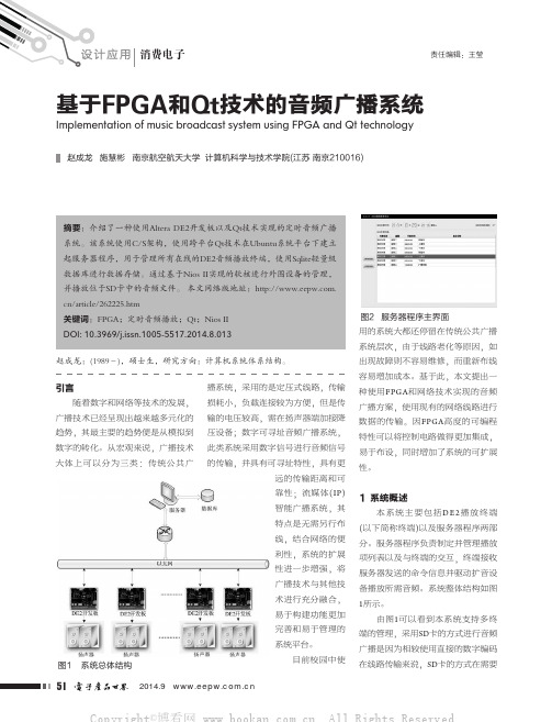
图2 服务器程序主界面
用的系统大都还停留在传统公共广播
系统层次,由于线路老化等原因,如
图1 系统总体结构
2014.9
51
播放音频时,只需由服务器发出相应的很短的命令报文至终端,这保证了各个扬声器播放在时间上的一致性。
不会因为系统网络架构及解码速度不将检测命令中指定的歌曲是否在
中,如果存在则播放对应的歌曲
息进行存储。
3 终端设计
通过在SoPC中查看并更改SD卡
音乐播放系统的链接结构,确定了系
统的硬件平台结构如图3所示,其主
要改动为增加了网络模块
图4 硬件系统处理流程
图3 硬件系统框图
图9 一个周期的ECG信号
的编写,在液晶上获得如图9所示的心电信号。
- 1、下载文档前请自行甄别文档内容的完整性,平台不提供额外的编辑、内容补充、找答案等附加服务。
- 2、"仅部分预览"的文档,不可在线预览部分如存在完整性等问题,可反馈申请退款(可完整预览的文档不适用该条件!)。
- 3、如文档侵犯您的权益,请联系客服反馈,我们会尽快为您处理(人工客服工作时间:9:00-18:30)。
1.系统设计特点及概述鉴于该系统设计包括多个专业扩声系统,为了达到系统整合的目的,同时又要保证系统稳定性和先进性,这里我们选用QSC公司最新推出的大型网络音频矩阵Q-sys系统为整套系统的核心。
由于Q-Sys系统具有极大的音频处理能力以及通道处理能力,实现Q-Sys 网络音频处理系统最大利用率,达到资源配置最优化。
1. Q-Sys系统介绍Q-Sys系统是美国QSC公司最新研制推出的一套大型网络音频矩阵处理系统。
该系统重新诠释了网络音频系统,具有:非凡的音频处理能力、超强的系统整合能力、磐石般的系统稳定性、简单易懂的可操作性。
Q-Sys系统主要由音频处理主机CORE、音频接口箱I/O FRAME、控制软件以及千兆网络组成。
所有的设备通过千兆网络连接起来即可完成工作。
如图1CORE主机CORE主机是Q-Sys系统的处理核心,音频系统中所有的音频信号处理、路由和控制信号全部是在这里进行的。
CORE主机分有三个型号:CORE1000、CORE3000、CORE4000。
三种主机分别可以处理64X 64、128X 128、512* X 512个音频通道,是当今世界上处理能力最强的音频处理主机。
CORE主机摒弃了传统音频处理主机采用DSP芯片进行音频信号处理的老方式,而采用全新的音频处理核心-多核64位中央处理单元进行音频信号处理。
采用这种全新的处理引擎后,CORE主机的信号处理能力远远大于传统采用DSP芯片作为处理核心的音频处理主机。
对比此前处理能力最强图2. CORE主机的PEAVEY的NION N6型音频处理主机,最小型的音频处理主机-CORE1000的音频处理能力是NION N6的五倍。
CORE主机内部内置了多种音频处理模块,如:分频器、混音器、自动混音台、噪声门、路由器、动态处理器、噪声发生器、参量/图示均衡器、动态显示器、音频文件播放器、RTA测试工具等等,能够满足各类场所音频系统的需要。
超强的处理能力、丰富的音频处理模块,使CORE具有充足的资源来进行音频信号处理,给音响系统设计师提供了一个自由的平台,供其任意设计自己想要设计的音响系统。
I/O FRAME 音频接口箱I/O FRAME是1U模块化音频接口箱,最大支持16个音频通道,采用32比特浮点信号处理方式和高端数模、模数转换器,使整套系统具有高保真音质效果。
机身集成四个卡槽,可以配置不同种类的输入输出接口卡。
目前支持的卡的类型为:CIML4 :图3.|/OFRAME音频接口箱麦克风/线路输入标准卡;CIML4-HP :麦克风/线路输入高性能卡;COL4 :标准线路输出卡;CODP4: QSC开关电源功放专用卡;CAES4: AES信号输入输出卡。
I/O FRAME可以和CORE安装在一起,也可以安装在音频网络可以覆盖的任何地方。
这种系统结构极大的增加了系统设计的灵活性,并且大大的削减了铺设模拟音频线缆的长度以及铺设成本。
由于所有的处理和控制都是在CORE中进行的,因此单个I/O FRAME的故障只能影响到这个接口箱的输入输出,而不会影响整个处理控制中心。
I/O FRAME机身集成了8个GPIO通道(继电器控制端、电压控制端和地线),GPIO可以通过软件配置为受干触点控制或者电位大小控制,也可以输出TTL 电平等控制信号,控制外部设备。
网络QSys 系统基于千兆以太网实时传输无损音频信号,一个千兆网线可以传输512 个音频通道,且最大支持网络十跳。
Q-Sys 系列内产品全部采用高质量的信号转换器,网络延时仅为0.667 毫秒,而QSys系统的任一输入到任一输出的最大总延时也仅仅为固定的2.5毫秒。
值得注意的是,这里的延时指的是系统固定延时,无论经过网络节点多少、无论内部增加多少DSP处理环境,系统整体延时为固定的2.5毫秒,为音响设计师在系统延时控制上提供便利。
Q-Sys 系列内产品CORE 和I/OFRAME 配备的为标准网络传输设备,内部的音频信号和控制信号在一个网络中进行传输,无需将控制和音频信号分成两个网络单独传输。
Q-Sys 系列内产品CORE 和I/OFRAME 均具有双网口,即支持双网络。
当一个音频网络瘫痪的时候,备用网络可以无延时的接替工作。
软件Q-Sys系统有一套非常直观、易懂、易操作的设计软件—“Q-Sys Designe” 音响系统设计师学习起来十分迅速。
Q-Sys Desig ner软件无论是在“在线”或者“离线”的状态下,都可以运行工作。
在离线状态下,音响设计人员可以学习使用软件,并在电脑上模拟系统运行,无需任何硬件设备。
方便大家进行系统设计和仿真模拟。
值得一提的是,Q-Sys Desig ner的仿真速度非常得快,可以大大节省我们在设计大系统时候的时间。
此外软件中集成了强大的帮助系统,在操作者需要的时候提供必要的协助。
系统设计简单得就像图示化的音频处理组件堆叠一样,会使得系统设计者更加专注于系统解决方案的设计而不是怎样去运行软件。
软件中还有很多十分使用的处理模块和工具,当一个设计师使用QSys系统的时候,当一些细节和小技巧被掌握后,系统的设计会更加有效。
除了设计软件之外,系统还可以制作图形化的控制界面。
控制界面的编辑就是将处理组件中的指示器和控制器拖拽到控制面板编辑器中,此外还能够在界面中添加图片、线以及其他一些图形等元素。
编辑器可以自动生成控制页面或者定制的控制页面。
系统操作人员就可以通过密码,使用友好的人机交互界面来控制整个音响系统了。
图4.软件界面系统的可靠性但凡大型的系统,一般对系统可靠性都具有很强的需求。
传统的模拟系统通常采用系统冷备份方式,当系统出现故障的时候,需要重新连接系统,容易出现系统连接错误、导致系统不能马上工作。
而Q-Sys系统具有热备份机制,可以实现实时的系统备份功能供用户选择。
如图5所示。
Nct'ivork A卩run ary Corphktwo卩k B B<jckup Cofe Procesior图5.主机、网络、接口箱自动热备份a)主机热备份Core支持双机热备份,两个主机互为备份,每300毫秒进行系统控制参数同步,当主机出现故障的时候,备份机可以马上接替主机工作,不会造成系统停止。
无需任何变成、无需任何软硬件增加,即可完成主机热备份b)音频接口箱热备份I/O Frame支持双机热备份,两个接口箱互为热备份。
当主接口箱出现问题的时候,备份接口箱可以自动接替主接口箱工作。
两个接口箱可以同时接在一套功率放大器上面,由于其内部设计了备机断开机制,因此不会出现输入阻抗减小一半的情况。
无需任何变成、无需任何软硬件增加,即可完成接口箱热备份。
c)网络热备份Q-Sys系统的所有设备均支持双网络,具有两个网口,实现网络系统的双备份。
当一个网络出现问题的时候,可以自动切换到另一个网络上面。
(无延时)d)功放热备份QSC功率放大器在配合Q-Sys系统工作的时候,可以实现N+1备份。
即用一台功率放大器就可以实现对N( N小于等于8)台功率放大器的备份工作。
实现功放备份的功能的时候,需要增加一台功放倒备器一DAB-801。
每台DAB-801可以实现一台两通道功率放大器备份4台两通道功率放大器,两台DAB-801可以级联,实现1台两通道功率放大器备份8台两通道功率放大器。
该功能多用于广播系统,在一些重要的会议场所也可以进行功率放大器的备份。
Q-Sys系统提供了这么全的备份功能,用户可以根据自身系统的需要,选择需要的备份设备。
对功率放大器和扬声器的整合Q-Sys系统不仅仅是一套网络音频处理系统,它还整合了QSC后端扩声设备-功率放大器和扬声器。
QSC所有开关电源功率放大器都可以通过Q-Sys系统进行远程遥控和监控(该监控功能还包含对功放后扬声器回路的监控),而所有QSC无源系列扬声器也全部集成到系统中,内置所有型号扬声器的“本征校正”音频处理模块,使得系统扬声器音质调整非常简单。
内置LUA编译器Q-Sys系统内置很多逻辑功能模块,帮助音响系统设计工程师设计功能更加强大的音响系统。
除此之外,系统还内置了LUA编译器,通过LUA语言变成, 设计逻辑功能更加复杂的音响系统。
2.本项目系统配置本系统包含会议扩声系统,采用一套Q-Sys 系统即可完成全部系统功能。
既实现了系统集中化管理和控制,又实现了资源优化配置目的。
配置原则:Q-Sys 系统在主机房配置系统主机CORE,然后通过网络连接每层所有的Q-Sys系统设备。
控制电脑也设立在主机房。
会议扩声场所分布在每个楼层,且有的楼层具有较多的会议室,基本配置原则是在每个会议室内配置一台I/O FRAME 音频接口箱,并根据房间内的音源输入数量(话筒、DVD 等)和扬声器输出回路确定需要的音频输入卡和输出卡的数量。
网络Q-Sys系统的千兆网系统可以单独建立一套千兆网系统,也可以利用大楼内部现有的千兆网络系统(资源优化配置)。
如果跟大楼内部网络系统共用网络的时候,需要给Q-Sys系统划定足够带宽的VLAN。
如果为了增加系统的可靠性,可以采用两套网络运行,Q-Sys系统支持双网络运行,且可以无缝切换主网络和备份网络。
Q-Sys系统的网络需求:a)必须为千兆以太网(使用千兆网交换机和千兆网线或者光纤均可)b)网络最大不可超过10 跳c)网络交换机支持QoSd)网络交换机端口至少支持4 个优先级功率放大器和扬声器配置原则会议扩声系统采用定阻方式驱动扬声器。
根据会议室空间大小,选择合适的AD 系列会议专用扬声器,并根据扬声器功率,选择合适的CX 系列定阻功率放大器即可。
3.系统特点介绍a)利用网络传输音频信号。
传输距离远、信号损失小。
采用模拟系统,既会造成线缆成本的大大增加、施工难度的增加、人力成本的增加;还会造成模拟音频信号在传输过程中信噪比下降和信号衰减,进而造成整个广播系统音质的下降,直观的感受就是语言清晰度不够、背景音乐音质不够优美等。
而Q-Sys 系统采用千兆以太网传输音频信号,可以有效的避免音频信号传输过程中的种种问题和施工上的难点。
利用一根千兆网线可以传输512 个音频通道,大大降低了施工成本和线缆成本;并且声音信号无压缩、无衰减损失。
b) 设备集中化管理。
管理智能化、人性化。
传统的系统通常不能够对系统所有设备进行管控、操作也不人性化,使用和维护起来十分不便。
如果是一个小的系统还无所谓,但是用在一个大型系统中那么使用起来就是非常繁琐了。
工作人员要面对大量的广播设备,需要经过专业的培训才能够了解系统的操作。
如果设备一旦出现问题,就要往返于设备间之间进行,增加系统的使用难度。
Q-Sys系统具有图形化、中文的,友好的人机交互界面,系统操作人员无需进行专业的培训即可根据才做界面上的中文提示进行系统操作。
并且系统具有权限管理机制,不同级别的系统管理人员具有不同的权限,需要根据授权或者密码对系统进行操作,防止系统误操作的发生。
