pFLD1 Z+使用说明
Pilz安全继电器说明书大全_1[5]
![Pilz安全继电器说明书大全_1[5]](https://img.taocdn.com/s3/m/d0e5953817fc700abb68a98271fe910ef02dae4b.png)
Pilz安全继电器说明书大全_1一、什么是安全继电器?安全继电器是一种用于监控和控制机器和设备的安全功能的电气设备。
它可以接收来自安全传感器(如急停按钮、安全门、光栅、光幕等)的信号,并输出相应的控制信号,以实现机器或设备的安全停止、启动、复位等操作。
安全继电器可以保护人员和机器免受意外伤害或损坏,提高生产效率和质量。
二、Pilz公司的安全继电器有哪些种类?Pilz公司是一家专业从事安全自动化领域的德国公司,拥有数十年的经验和技术积累。
Pilz公司在1987年推出了世界上第一个用于急停的安全继电器(PNOZ),从此开创了安全继电器的新时代。
如今,P ilz公司拥有多个系列的安全继电器产品,可以满足不同的应用需求和标准。
下面简要介绍一下Pilz公司的主要安全继电器系列:myPNOZ:这是一种具有内部组合逻辑的模块化安全继电器,可以根据用户的个性化需求进行预装配,因此易于安装和调试。
用户可以在myPNOZCreator中单独创建自己需要的安全解决方案,并按批量量身定制。
myPNOZ适用于需要监控多达16个安全输入,并需要实现AND和OR连接的应用场合。
PNOZsigma:这是一种在最小的宽度上实现最大的功能的紧凑型安全继电器,具有可调节的操作模式和时间,以及可扩展性。
PNOZsigma 适用于需要节省空间和成本,并具有高度灵活性和可靠性的应用场合。
PNOZX:这是一种适用于每种功能的经典型安全继电器,采用机电式触点和宽电压范围。
PNOZX适用于各种传统和常见的安全功能,如急停、安全门、光栅等。
PNOZcompact:这是一种方形、简易、黄色的基本型安全继电器,是大批量系列机器制造商的理想选择。
PNOZcompact适用于监控简单且固定不变的安全应用,如急停或双手控制。
PNOZelog:这是一种无磨损且易于连接的半导体型安全继电器,具有扩展诊断功能。
PNOZelog适用于需要高开关频率和长寿命,并且对故障诊断要求较高的应用场合。
西门子AMDP-D系列电动机保护器使用手册说明书

第七章 AMDP-□/D系列电动机保护器7.1、AMDP-□/D 系列电动机保护器AMDP-□/D □ □ □1: 1常开、常闭(或仅1常开)继电器触点(AC 250V/10A(阻性负载)、DC 30V/10A);2: 2常开、常闭继电器触点(AC 220V/5A(阻性负载)、DC 30V/5A);0:接地、短路、缺相、堵转、电流不平衡、过载;1:接地、短路、缺相、堵转、电流不平衡、过载、零序;2:接地、短路、缺相、堵转、电流不平衡、过载、欠载;3:接地、短路、缺相、堵转、电流不平衡、过载、过压、欠压;4:接地、短路、缺相、堵转、电流不平衡、过载、欠载、过压、欠压;5:接地、短路、缺相、堵转、电流不平衡、过载、零序、欠载;6:接地、短路、缺相、堵转、电流不平衡、过载、零序、过压、欠压;7:接地、短路、缺相、堵转、电流不平衡、过载、零序、欠载、过压、欠压;0:无通讯接口、无4-20mA输出、无运行状态输出;1:4路4-20mA输出;2:MODBUS、RS-485通讯接口;3:PROFIBUS通讯接口;4:MODBUS、RS-485通讯接口,4路4-20mA输出;5:6路故障类型、1路预警、1路报警输出,1路故障清除输入;6:5路运行状态输出,1路故障清除、1路选通输入;7:6路故障类型、1路预警、1路报警、2路4-20mA输出,1路故障清除输入;8:5路运行状态、4路4-20mA输出,1路故障清除、1路选通输入;5 位LED数码管显示3相及零序电流、电压、故障代码、保护参数,有通讯接口、4-20mA输出、运行状态信号输出;保护器额定电流(A),是 0.5、1、2、5、10、20、50、100、150、200 之一;AMDP加H,即AMDPH,是重负载起动型保护器,AMDPH适用于风机等重负载起动,起动时间长,过载电流倍数大(大于7倍),详细技术数据请参见AMDPH-□/D□□□使用说明;AMDP-□/D0、D1、D5、D6、D7、D8系列主单元 AMDP-□/D0、D1、D5、D6、D7、D8系列电流检测单元及电缆AMDP-□/D2、D3、D4系列主单元 AMDP-□/D2、D3、D4系列电流检测单元及电缆主要特点:DSP为核心,数字设定、数字显示,保护功能完备、保护性能可靠。
Pilz安全继电器说明书大全_1[2]
![Pilz安全继电器说明书大全_1[2]](https://img.taocdn.com/s3/m/b82abc75842458fb770bf78a6529647d26283468.png)
Pilz安全继电器说明书大全_1Pilz安全继电器的主要产品系列myPNOZ:具有内部组合逻辑的模块化安全继电器,可以根据个性化需求进行预装配,易于安装和调试,适用于需要监控多达16个安全输入的应用¹。
PNOZsigma:在最小的宽度上实现最大的功能,具有可调节的操作模式和时间,以及模块化设计,适用于各种安全功能的监控²。
PNOZX:安全适用于每种功能,采用无源和双继电器技术的机电式触点,具有通用电源和直插式端子,适用于所有常见的安全功能的监控³。
PNOZcompact:方形,简易,黄色,是大批量系列机器制造商的理想选择,适用于基本的安全功能的监控⁴。
PNOZelog:易于连接,无磨损,扩展诊断,适用于需要高速开关和低功耗的应用。
PNOZpower:高负载8A至16A,可以直接开关电机负载,具有模块化输出触点和直插式技术。
Pilz安全继电器的功能特点国际认证:符合国际标准和法规,如EN ISO 13849-1, IEC 62061, IEC 61508, UL, CE等。
便捷的诊断选项:提供LED指示灯、显示屏、故障存储器等设备或软件,帮助用户快速定位故障原因,并提高设备可用性和缩短停机时间。
全面的解决方案:包含评估设备、兼容的传感器技术以及控制与信号装置,实现从传感器到执行器的完整安全链。
高安全性:提供高达PL e或SIL CL3级别的安全保护,防止人员受伤或设备损坏。
Pilz安全继电器的使用方法选择合适的产品系列和型号:根据需要监控的安全功能、输入输出数量、连接方式、操作模式、时间参数等因素,选择最适合自己应用场景的产品系列和型号。
可以参考Pilz官网或产品目录中提供的产品对比表或选择指南。
连接线路:按照产品说明书中提供的接线图或示例,正确连接好所有线路,并检查是否有短路、断路或接反的情况。
注意遵守产品说明书中规定的电压、电流、功率等参数,以及安全距离、接地、屏蔽等要求。
福尼亚泵操作
医生调节模式
“医生调节”模式被设计为只允许知 道PIN(个人认证的号码)的人进入,以 修改餐前量和基础量的最大值和日总量限 制,在此模式下可改变餐前量输注模式, 并提供报警记录。
医生调节模式
设 餐 检 临 置 前 查 基
0000 请输入密码
SEL A CT
SEL
A CT
在主画面上,同时 按▲ 键然后释放, 则进入如下图所示的 PIN调节模式画面。 按上下键改变每一 位数,按SEL键在数位 之间进行切换。输入完 毕按ACT键。
医生调节模式
密 码正 确 按ACT键进 入 医 生调 节
SEL A CT
如果密码正确,则显示如上画面,ACT进入。 若不正确,则回到初始画面。
医生调节模式
基 础限 量:2.0U 餐 前限 量:40.0U 日 总限 量:160U 输 注模 式:A1
SEL
A CT
按SEL键可以选择调整胰岛素的基础最大值、餐前量最大值、日输 注总量最大值和模式设置。 基础限量:0.1—4U 餐前限量:0.1—87U 日总限量:0—250U 输注模式:A0、A1、B0、B1 出厂默认设置:基础限量:2U 餐前限量:10U 日总限量:60U 输注模式:A1
检查(记录1)
00-01 0.5U 基 础总 量 = 12.0U
SEL A CT
1、显示基础量的设置。 ▲ 键查看不同时段的基础量。 SEL键转入下一记录页面,ACT键退出。
检查(记录2)
USE 12U 00 : 00 早餐 MAX 250U 0.0U 87U
SEL A CT
2、餐前量设置的记录,SEL键切换到早餐、午餐、晚餐、 餐前大剂量进行查看。 SEL键转入下一记录页面,ACT键退出。
美国卓尔除颤起搏监护仪操作培训

16
无创体外起搏功能
适应症
药物治疗无效的、血流动力学不稳定的心动过 缓。
药物治疗效果不好的、血流动力学不稳定的心 动过速。
心脏骤停中的心室静止有时可以使用,但室颤 患者是不可使用的。
17
无创体外起搏功能
事件标记 事件标记选项
21
报警设置 报警状态一般有翻 开、关闭和自动三 种。 自动的含义是以患 者当前的监测数值 的80%作为下限, 120%作为上限自动 设置的。 通过增加和减少按 钮进行数值调节
22
修改、设置日期和时间 按住最右侧的多功能按键,同时开机到监
护档,进入界面〔如右图〕,然后设置。
快速测 血压
自动测 血压
袖带充 气压力
自动测血压的 时间间隔
27
除颤器的维护
主机维护 1、主机面板可使用湿布擦拭干净
2、主机30焦耳自检
开机到除颤档,能量调到30焦耳,除颤板在
主 机上,使用除颤板放电〔在短路模式下〕,
测试通过,那么仪器工作正常。一般2周自检一次。
28
除颤板维护 1、在使用后可用生理盐水或温肥皂水擦拭 干净。 2、不可使用强酸或强碱或酮类物质擦拭 3、不可将除颤板浸在任何液体中
灵敏度 平均值
25
无创血压监护
无创血压采用振荡法测量
无创血压测量的类型
单次测血压:只要按下面板上测血压按钮,就启
动测
血压一次〔在前面板上按键〕。
连续测血压:5分钟快速测量10次〔在菜单项选择 择按键〕。
自动测血压:按设定的间隔时间〔如30分钟〕, 自动测量血压〔在菜单项选择择按键〕 。
艾默生灵冻

使用说明书我们的愿景:艾默生环境优化技术将与我们的合作伙伴一起,向世界范围的客户提供整合的环境优化解决方案,提高人类生活舒适度,保障食品安全,保护环境。
领先技术造就一流产品艾默生环境优化技术,作为艾默生业务板块,是世界领先的家用及工商业应用领域采暖、空调和制冷解决方案提供商。
公司以卓越的技术、工程、设计、销售、培训和服务为全球客户提供定制的气候控制整体解决方案。
艾默生环境优化技术的创新技术,帮助提升人体舒适度、护航食品保鲜,保护环境。
和 ,以节23ZX系列冷凝机组声明感谢购买艾默生环境优化技术提供的ZX系列冷凝机组。
ZX系列冷凝机组在制冷量和运行范围上均表现出市场领先的品质。
ZX冷凝机组专为中温和低温制冷应用而设计,具有高可靠性和高效率的特点,并能持续监控压缩机运行状态,显示冷凝机组的运行或故障状态。
为保证机组的安全可靠运行,ZX系列冷凝机组的安装必须遵循行业标准,其选型、安装和维修必须由专业人员进行。
本用户手册并未包含所有制冷设备安装需遵循的行业准则。
对于由无经验或未经专业培训的人员操作、或由于错误的安装设计造成的损失,将不作为合理的追责理由。
如有任何疑问,请向当地销售办公室提供机组铭牌上的机组型号和序列号进行咨询。
如随机附带的接线图与本手册中的接线图发生不符情况,请以随机附带的接线图为准。
ZX冷凝机组介绍ZX中温、ZXB中温、ZXD数码中温和ZXL低温系列冷凝机组已享誉市场,以其节约能耗、友好的控制体验在亚洲市场取得巨大成功。
ZX/ZXB/ZXD/ZXL机组在亚洲范围内应用于著名的终端用户和冷链零售商现场。
ZX平台产品在全球市场上得到广泛认可,特制开发的机型已出口美国、欧洲和中东市场。
收到机组的检查所有机组运输前均充有一定正压的干氮气。
机组和包装均贴有明显的标签。
机组截止阀上配有维修接口以便检查机组保压状态。
注意!当您从艾默生或授权代表处收到机组时,对每一台机组进行保压检查是非常重要的。
如发现保压已消失,请联系艾默生或授权代表。
POWER-Z FL001中文使用说明书
POWER-Z FL001使用说明书一、外观显示介绍 (2)1、按键接口 (2)2、主屏显示 (3)二、电压电流测量 (8)1、USB PD协议测量 (8)2、VOOC、DASH测量 (9)3、其他快充测量 (10)三、容量能量测量 (13)四、协议诱骗 (15)1、高通QC2.0诱骗 (15)2、高通QC3.0诱骗 (17)3、华为FCP诱骗 (17)4、华为SCP诱骗 (18)5、三星AFC诱骗 (19)五、充电线线阻测量 (21)六、设置 (26)1、测试设置 (26)2、校准设置 (29)3、显示设置 (34)4、系统设置 (37)一、外观主显示介绍1、按键接口2、主屏显示界面主界面①主界面②主界面③主界面④主界面⑤主界面⑦二、电压电流测量1、USB PD测量POWER-Z FL001下方USB-C接口接左侧PD电源适配器或移动电源,上方USB-C 接口接右侧移动电源或其他负载。
注意:①如果上方USB-C接口接电源适配器或移动电源,下方接负载,电流一项会显示红色,表示电流此时是反向的;②如若按上图正确接线后POWER-Z FL001无反应,将接入POWER-Z FL001的两条数据线,选择其中任意一条的USB-C接口旋转180°后重新插入即可。
2、DASH、VOOC测量2.1 DASH闪充采用USB-C数据线,将数据线USB-A端连接适配器,USB-C端链接连接FL001底部的USB-C接口。
另外再准备一条DASH数据线,USB-A端接入FL001尾部,USB-C端接手机即可。
2.2 VOOC闪充采用MicroUSB数据线,只需将连接电源适配器的数据线MicroUSB 端插入FL001底部的MicroUSB口,其它的参照上图即可。
3、其他协议测量①QC3.0/2.0测量②FCP测量③SCP测量④AFC测量⑤Apple测量⑥PE测量三、容量能量测量该功能主要用于移动电源、电池的放电容量测试,可记录10组数值。
ZOLL除颤(监护)仪操作流程
ZOLL除颤(监护)仪操作流程ZOLL除颤(监护)仪操作流程①插上电源,正确开启除颤仪,调至监护位置,观察显示仪上心电波形。
②将病人摆放为复苏体位,迅速擦干患者胸部皮肤,贴上电极片:红色(R)右锁骨中线下0.5cm;黄色(L)左锁骨中线下0.5cm;绿色(F)左下腹(左侧肋弓处)。
③调至除颤位置,选择除颤能量:直线双向波用120J;再根据情况选择;双向波最高200 J;儿童:首次2J/Kg,后续电击的能量为4J/Kg④涂导电糊,导电糊均匀涂在电极板上⑤充电:按充电按扭,除颤仪自动充电至显示屏显示“充电完成”。
⑥放置电极板:分别置于胸骨右缘第二肋(心底部),左锁骨中线与第五肋间相交处(心尖部)。
电极板与皮肤紧密接触。
⑦清场:确认没有人接触床边,操作者身体后退一小步,不能与患者接触;放电:双手同时按压放电键。
⑧除颤结束,移开电极板。
⑨抢救完毕,电极板正确回位,取下电极片,擦净患者皮肤,关机,关电源。
⑩整理用物。
除颤仪操作流程的注意事项1、除颤仪到位前,持续有效的CPR.2、除颤后紧接着5个遁环的CPR,再评估节律,按需要决定是否再除颤.3、操作者的手应保持干燥,不能用湿手握电极板.4、放电时在电击板上应施加一定有力量,使电极板与病人皮肤密合,以保证较低的阻抗,有利于除颤成功,同时也避免烧伤病人的皮肤.5、导电糊不应涂在两电极板之间的皮肤上,以免除颤无效.6、胸部有植入性的装置时,电极板应放在距该装置2.5cm的位置,除颤后应检查其功能.7、切忌将电极板直接放在治疗性贴片,监护仪贴片,导电线的上面.8、病人大量出汗,则在除颤前,应迅速将病人的胸部擦干.。
PFERD 切割钢筋线胶带系列用户手册说明书
17Catalogue Page77General information 3 Safety notes 5 Packaging, transport and storage 6 The fast way to the best tool 8CHOPSAW HDdia. 300–400 mm 12LABORdia. 150–400 mm 15HEAVY DUTYdia. 250–600 mm 16Reducing rings 18Products made to orderdia. 250–2,000 mm 19Support and servicePFERD offers you individual targeted support to solve your application problems. The experienced field staff of PFERD will be pleased to assist you.With their expertise, our technical advisers will also help you to solve complex problems related to applications and use.Due to our many years of collaboration with manufacturers of cut-off grinding machines inGermany and abroad, we can also advise you on the design of appropriate machining equipment.Please do not hesitate to contact us for further information.QualityStationary cut-off wheels from PFERD are developed, manufactured and tested in accordance with the strictest quality requirements.Research and development, our own machine and plant construction, and the continuous testing and further development of the quality and safety standards in our own laboratories all guarantee the high PFERD quality.PFERD quality management is certified according to ISO 9001.Products made to orderAdvantages of stationary cut-off grinding■Universal cutting process for all steels and castings, non-ferrous metal alloys, special alloys such as nickel and titanium-based alloys, as well as materials on which sawing and flame cutting are difficult or impossible.■Due to smooth cutting surfaces and blank cuts in cold cutting-off, no post-processing is required.■Short cutting times regardless of the material quality.■Significantly lower burr formation with hot cutting-off than with hot sawing. ■Lower noise levels than with hot sawing, for example: Hot cutting-off: 85 to 95 dBA Hot sawing: 105 to 110 dBA■Consistent cutting quality over the entire life of the cut-off wheel due to its continuous self-sharpening qualities.■Cutting of already cooled rolled or forged parts in hot cut lines is possible.ApplicationsCut-off grinding is one of the most powerful and cost-effective cutting processes and is used in the following areas: ■Rolling mills ■Foundries■Machine engineering ■Steel construction ■Maintenance of rails■Forging plants and their finishing processes ■Laboratories37Catalogue PageCut-off processesAccording to the material and the application, cut-off processes differ depending on the positioning and relative motion of the cut-off wheel and workpiece.Chop stroke cutApplication area:■For cutting individual workpieces as well as small or slim material layers. ■Very common cut-off process.Cutting process:■Cut-off wheel cuts the workpiece in a radial movement over a joint mid-point.Advantages: ■Low vibration.■Short cutting times.■Less load on cut-off wheels for smaller material dimensions.Oscillation cutApplication area:■For cutting sprues and risers in foundries.■Demanding tasks in wet cut-off grinding.Cutting process:■Cut-off wheel moves into the work-piece to be cut with additional forward and backward movements in the horizontal cut. Advantages:■Lower drive output required. ■Low workpiece temperature. ■Optimum removal of chips.Horizontal cutApplication area:■For cutting multiple adjacent work-pieces, as well as slabs, plates and sheets.■In particular on the approach side of the rolling mill after the cooling bed.Cutting process:■Cut-off wheel cuts the entire layer width of different cross sections in one cycle.Advantages:■Short cutting times.■Very high throughput capacity.Index cutApplication area:■For cutting very large round solid material and blocks.■In particular in steel works and foundries.Cutting process:■The workpiece is cut with severalpartial cuts. After each partial cut, the workpiece is rotated (2–4 partial cuts, 180–90° rotation, depending on the material dimensions).Advantages:■Working on very large material cross sections is possible with smaller wheel diameters.Rotary cutApplication area:■For cutting very large pipes as well as round solid materials.Cutting process:■The workpiece is continuously rotated during the cutting process.Advantages:■Use of small wheel diameters is possible.■Lower drive output required. ■Low workpiece temperature.Differentiation of cut-off grindingA differentiation is made between cold, warm and hot cutting-off, depending on the material temperature of the workpieces.* Please adhere to the maximum operating speed of the cut-off wheel.Safety notes:The safe use of PFERD tools depends largely on proper clamping systems. Both flanges be-tween which a grinding tool is mounted must have the same outer diameter and same sup-port area (according to EN 13218, ANSI B7.1, AS 1788.1).Proper clamping of cut-off wheelsThe correct clamping of the cut-off wheel is a prerequisite for optimum performance and isessential to ensure user safety. The adjacent illustration shows the right way to do it:➊ Machine spindle with high concentricity.➋ Equally sized flanges.➌ Intermediate paper layers, if required for secure clamping and safe use. Our recommendations:■After every second wheel change, change the intermediate paper layers. ■As from a wheel diameter > 400 mm, always use intermediate paper layers.Intermediate paper layerPFERD is a founder member of oSaTogether with other renowned manufacturers, PFERD has voluntarily undertaken to produce quality tools conforming to the most exacting safety standards.Member companies of oSa (the Organization for Safety of Abrasives) are committed to con-tinuous product safety and quality monitoring.PFERD tools carry the oSa mark.Safety standardPFERD cut-off wheels conform to the highest safety requirements and are marked accord-bonded abrasives.Maximum operating speedThe maximum permissible operating speed unused wheels. For safety reasons, these must never be exceeded.Safety notes=Wear eye protection!=Wear hearing protection!=Wear a dust mask!=Wear gloves!=Please read the safety notes!=Do not use if damaged!=Not permitted for hand-held or manually guided grinding!German Abrasives AssociationPlease observe the safety notes of the German Abrasives Association (VDS). Further informa-tion can be found at: Please observe the userinformation provided with all products on the safe use of stationary cut-off wheels as well as the user information for the grinding machine used.FEPAThe FEPA safety recommenda-tions can be downloaded at .000000000000000Crate Pallet BoxPackaging labelTransport and storageTo avoid damage to the cut-off wheels through improper transport or adverse environmental influences during storage, e.g. UV radiation, temperature or humidity, please observe the following advice:■■As far as possible, transport and store cut-off wheels in their original packaging lying on a flat surface, e.g. on a shelf or vertically in racks.■■Avoid bending the tools.■■Ensure that the cut-off wheels are stored in dry, frost-free rooms with consistent temperatures.■■Use supplies in the order of their arrival.Recommendation:Room temperature: 18–22°C Relative humidity: 45–65%No direct sunlightAdvice on the storage of conical wheels (CT)Conical cut-off wheels must be stacked with intermediate paper layers, so that the tapered area is supported and bending of the cut-off wheels is avoided.PFERD supplies conical cut-off wheels with intermediate paper layers included.Product lines and colour codingProduct labelsSafety informationHandling grinding tools is dangerous. Observe all safety rules and regulations.oSa – Organization for the Safety of AbrasivesAs a founder member of oSa, PFERD has voluntarily undertaken to produce quality tools conforming to the most exacting safety standards. Member companies of oSa are committed to continuous product safety and quality monitoring.Information barHere you will find the product line and the dimensions.Material informationThe bottom section of every label indicates the material or materials for which the tool is suitable.EAN(European Article Number)Advice on tool driveThe pictogram shows on which drive the tool can be used.Hardness gradeThe hardness denotes thestrength with which the abrasive grit is held by the bond within the grinding tool.The hardness is indicated with a letter (see table below).Product group selectionSG RAIL SGP HD STEELPSF CHOP STEEL ★★Tool of hardness K, which cuts very easily, with a middle fabric. For aggressive cutting with minimized burr formation.Advantages:■High economic efficiency due to long tool life.■Fast work progress thanks to high cutting performance.■to less lateral friction.■For multi-purpose cutting work.Materials that can be worked:steelApplications:cutting of solid material, sections and pipesAbrasive:output of up to 3 KW.PSF CHOP STEELOX ★★Tool of hardness K, which cuts very easily, with a middle fabric for steel and stainless steel (INOX). For aggressive cutting with minimized burr formation.Advantages:■High economic efficiency due to long tool life.■Fast work progress thanks to high cutting performance.■to less lateral friction.■For multi-purpose cutting work.Materials that can be worked:steel, stainless steel (INOX)Applications:cutting of solid material, sections and pipesAbrasive:output of up to 3 KW.107CataloguePageSG CHOP STEEL ★★★Tool of hardness K, which cuts very easily, with a middle fabric. For aggressive cutting with minimized burr formation.Advantages:■Maximum economic efficiency due to very long tool life.■The fastest work progress thanks to very high cutting performance.■to less lateral friction.■For demanding cutting work.Materials that can be worked:steelApplications:cutting of solid material, sections and pipesAbrasive:output of up to 3 KW.SG CHOP STEELOX ★★★Tool of hardness K, which cuts very easily, with a middle fabric for steel and stainless steel (INOX). For aggressive cutting with minimized burr formation.Advantages:■Maximum economic efficiency due to very long tool life.■The fastest work progress thanks to very high cutting performance.■to less lateral friction.■For demanding cutting work.Materials that can be worked:steel, stainless steel (INOX)Applications:cutting of solid material, sections and pipesAbrasive:■Use only on stationary machines with an output of up to 3 KW.117Catalogue PageSG CHOP HD STEEL ★★★Tool of hardness L or O with two outer fabrics. For cutting work that requires high stability.Advantages:■High lateral stability thanks to reinforcing outer fabrics.■Maximum economic efficiency due to very long tool life.■For demanding cutting work.Materials that can be worked:steelApplications:cutting of solid material, sections and pipesAbrasive:Aluminium oxide A Matching tool drives:SG CHOP HD STEELOX ★★★Tool of hardness L, which cuts very easily, with two outer fabrics for steel and stainless steel (INOX). For cutting work that requires high stability.Advantages:■High lateral stability thanks to reinforcing outer fabrics.■Maximum economic efficiency due to very long tool life.■For demanding cutting work.Materials that can be worked:steel, stainless steel (INOX)Applications:cutting of solid material, sections and pipesAbrasive:Aluminium oxide A Matching tool drives:SG CHOP HD CAST + STONE ★★★Tool of hardness L, which cuts very easily, with two outer fabrics. For cutting work that requires high stability.Advantages:■High lateral stability thanks to reinforcing outer fabrics.■Maximum economic efficiency due to very long tool life.■For demanding cutting work.Materials that can be worked:cast iron, stone, plastics, aluminium, other non-ferrous metalsApplications:cutting of solid material, sections and pipesAbrasive:Silicon carbide C Matching tool drives:1377Catalogue PageSG RAIL STEEL ★★★Tool of hardness Q for fast and economic cutting of rails.Advantages:■The fastest work progress due to aggressive abrasive.■Safe cutting work thanks to the optimumAbrasive:Aluminium oxide A Matching tool drives:147CataloguePageSG LAB STEEL ★★★Tool of hardness H, which cuts very easily, with a middle fabric for steel and cast iron. For producing precision cuts and cutting laboratory samples quickly.Advantages:■Special tool for metallographic sampling thanks to aggressive abrasive.■Safe cutting work thanks to the optimum cutting quality.■High stability thanks to reinforcing middle fabric.Materials that can be worked:steel, cast ironApplications:Cutting of solid material, sections and pipesAbrasive:Aluminium oxide ARecommendations for use:■Also suitable for wet cutting applications.Matching tool drives:SG LAB HD STEELOX ★★★Tool of hardness H, which cuts very easily, with two outer fabrics for steel and stainless steel(INOX). For cutting work that requires high stability. For producing precision cuts and fast cutting of laboratory samples.Advantages:■Special tool for metallographic sampling thanks to aggressive abrasive.■Safe cutting work thanks to the optimum cutting quality.■Extremely sturdy thanks to reinforcing outer fabrics.Materials that can be worked:steel, stainless steel (INOX), cast iron Applications:cutting of solid material, sections and pipesAbrasive:Aluminium oxide ARecommendations for use:■Also suitable for wet cutting applications.Matching tool drives:SGP HD STEEL ★★★★Tool for the highest cutting work demands. Particularly suitable for use in finishing work.Advantages:■Ultimate economic efficiency due to optimal tool life.■Fast work progress thanks to excellent cutting characteristics.Materials that can be worked:steelApplications:cutting of solid material, sections and pipesAbrasive:Aluminium oxide AMatching tool drives:167CataloguePageZIRKON SGP HD CAST + STEEL ★★★★Tool for the highest cutting work demands. Particularly suitable for cutting risers and sprues. Specially developed for use in foundries.Advantages:■Ultimate economic efficiency due to optimal tool life.■Fast work progress thanks to excellent cutting characteristics.Materials that can be worked:cast iron, steelApplications:cutting of solid material, sections and pipesAbrasive:Zirconia alumina/aluminium oxide ZA Matching tool drives:1777Catalogue PageCut-off wheels for stationary applicationsReducing ringsReducing ringsReducing rings enable secure adjustment of the standard centre hole to a reduced centre hole dimension.Advantages:■Flexible adjustment to the prerequisites of the drive system.■With stop collar, to prevent the ring from pushing through the centre hole of the cut-off wheel.Safety notes:■Ensure that the flanges on the drive system are backed off in order to mount the tool securely.187CataloguePageCut-off wheels for stationary applicationsProducts made to orderCUSTOMIZEDup to dia. 2 mDimensions and designs to meet customer requirementsOther types and centre hole diameters are available on request. Please contact us for further information.Catalogue PageCut-off wheels for stationary applications METALCORE cut-off wheelMETALCORE typeThe steel-core cut-off wheel, developed and patented by PFERD, is characterized, as compared to the conventional type, by its solid steel body ➎ constructed in layers which does not contain any abrasive. The special tool structure has the following advantages:1. R educed cutting costs due to the use of smaller clamping flanges:■Larger deployable grinding area.■Cutting of larger material cross sections possible due to greater immersion depth of the cut-off wheel.■Smaller wheel stub diameter.2. L onger tool life due to:■More stable cut with less vibration.3. R educed cut-off wheel width for chop stroke cut due to increased lateral stability:■Shorter cutting times and higher material throughput rate with low-power cutting machines.■Less loss of cut material.■Reduced chips or cinder waste.4. N o cost for the disposal of the old wheel Conventional typeFor stationary cut-off grinding, resinoid-bonded, fibre-reinforced cut-off wheels are used, which are essentially composed of four components:➊Abrasives➋Bond, which holds the abrasive grit in the cut-off wheel➌Fabric layers/flange fabric, which ensure that the cut-off wheel is secure and stable➍Active grinding fillers➌ Flange fabric➌ Fabric layers➊ + ➋ + ➍ Bonded abrasives➎ Steel coreSolid steel bodyconstructed in layersMaximum utilisation ofabrasives CataloguePage。
腹膜透析机操作说明
腹膜透析机操作说明指示灯:DRAIN(引流)、FILL(注入)、DWELL(留置)、POWER LOSS(断电) 指示灯显示:表示治疗所处的阶段触控按键:1( START(开始)——开始治疗2( VOLUME(容量)——显示透析液的流量3( UF(超滤量)——超滤量即脱水量。
上方数值——最后一个周期的超滤量下方数值——以上所有周期累计的超滤量 4( TIME(剩余时间)——按一次为该治疗期结束的剩余时间按两次为全部周期结束的剩余时间 5( STOP(停止)——中断运转或消除报警6( BYPASS(旁路键)——须按“STOP”键后,按此键,可以跳过警示状态或直接跳到下一步骤。
7( STANDBY(暂停)——须按“STOP”键后,按此键,可使机器暂停10分钟。
注意:只能在留置期使用。
8( X-DRAIN(受控引流)——须按“STOP”键后,按此键,即开始引流,再按“STOP”键后停止。
9( VOLUME钮——控制声音强弱度BRIGHTNESS钮——控制屏幕的亮度PROGRAM——调节治疗程序:CCPD FILL VOLUME:注入量CCPD FILL TIME:注入时间CCPD DWELL TIME:存腹时间CCPD DRAIN TIME:引流时间键——按此键可增加输入数字键——按此键可减少输入数字SAVE——存入腹透机的记忆中REVIEW——显示面板出现下一个治疗程序及数值操作步骤:1( 准备用物:腹透机、四插孔管、5000ML腹透液、碘伏夹子 2( 打开电源,按START键开机3( 先放称重袋上(上方)的腹透液4( 按PROGRAM调整调节治疗程序CCPD FILL VOLUME:注入量,按SAVE键CCPD FILL TIME:注入时间,按SAVE键CCPD DWELL TIME:存腹时间,按SAVE键CCPD DRAIN TIME:引流时间,按SAVE键NEMBLE OF CIRCLE :循环数LAST BAG Volume:末袋量LAST BAG FILL TIME:末袋注入时间 5( 待显示面板显示,按指示标志上管路6( 排气7( 按START键8( 按指示打开每个管路的夹子 9( 按START键三次开始运行 10( 待循环开始时打开腹部短管开关注意:上下两称及电源不要触摸。
PFERD 钢锯链刃锐锐工具说明书

TRUST BLUEPFERD (the German term for horse) is leading in the development, produc-tion and support, as well as in the distribution, of tool solutions for work on surfaces and material cutting. In keeping with a tradition that dates back more than 200 years, PFERD operates as an independent, internation-ally oriented, family-owned company geared towards the long term.For 200 years, the company has been manufacturing files of a world-renowned high quality. Many years of experience as a tool manufac-turer have led to the steady development of PFERD files. Application-oriented file shapes and cuts for industry and crafts guar-antee good economic value. Even after long use, PFERD files achieve high stock removal rates and an excellent surface quality.State-of-the-art production technology and strict quality controls guarantee the outstanding PFERD quality.PFERD is certified according to ISO 9001.We have compiled our years of experience and our know-how on maintaining saw chains in this pocket guide.For further information on servicing and maintainingsaw chains and repairing other forestry equipmentand accessories, please also refer to our brochure“PRAXIS FOCUS – PFERD tools for forestry”.2Why sharpen saw chains?Sharpening early enough ensures:■■Less wear to the cutting setand chain saw.■Better cutting performance and■higher cutting speed.■Less fuel consumption and■lower exhaust emissions.■■Fewer vibrations and betterwork comfort.■Lower expenditure of force and■less physical strain.■Reduced accident risk.■L Note■By resharpening early■enough, less material needsto be removed and the timeneeded to sharpen is con-siderably reduced.L NotePlease observe the current instructions and recommenda-tions of the manufacturer of the respectivechain saw or device.3Components of a saw chainThe saw chain on a chain saw works according to the plane tooth principle . The chips are lit-erally “planed out” of the material.The cutting tooth automatically works itself into the material. The cutting corner of the tooth carves out the wood shavings and the side plate edge cuts them off the side of the material.The depth gauge determines the thickness of the wood chips and limits the penetration depth of the tooth into the wood.Function of a saw chain 4L Note■■The optimum sharpening result is achieved by the interaction of all angles .■■Recommended angles vary. Follow the manufacturer’s specified angles for your saw chain.L Note■■For safety reasons and in order to reduce vibrations, it isrecommended to readjust the shape of the depth gauge as well.Angles to be consideredDepth gauge distanceThe distance between the cutting corner and the depth gauge has to be the same on all cutting links.Depending on the chain type, pitch and application, manufacturers‘ recommendations regarding the depth gauge distance are .025” (0.65 mm) or .030” (0.75 mm).5■■byrivets by two■■Determining the file diameterL Notes■In the case of so-called Low Profile (LP) chains, please refer to ■the respective manufacturer‘s details.■■When sharpening a saw chain, always wear suitable gloves and safety glasses to reduce the risk of injury.6L Notes■■Make sure to only work on the cutting tooth. Do not accidentally damage other components .■■The file only removes material while it is moved forwards. There-fore, please make sure not to touch the chain when moving the file back in order to prevent damages to the cutting teeth and the file itself.■■1/5 (20 plate .■■■■A preferred.■■File from the open inner side of the tooth outwards .■■Make sure to apply light and even pressure to the file while moving it forwards.Depending on the chain or tooth type and the manufacturer recom-mendation, the file is controlled horizontally = 90° to the guide bar or with + 10° gradient. The sharpening angle might also differ.You can find the recommendations of chain manufactur-ers in our PRAXIS FOCUS “PFERD tools for forestry“.7The sharpening process:■■Clean the saw chain.■■Check the saw chain for damages and, if need be, replace damaged components or dispose of the chain.■■Secure the chain saw.■■Identify the shortest tooth (for orientation) on both sides.■■First sharpen all cutting teeth on one row and then move to the other side.■■Check the sharpening result:-Has the sharpening angle been maintained?-Are the side and top plate angles correct?-Are the tooth lengths consistent?■■Check the depth gauge distance:-If necessary, reduce the height of the depth gauge using a flat depth gauge file.-Adjust the shape of the depth gauge.L Notes■■Increase the chain tension during the sharpening process to prevent the cutting teeth from moving or lifting.Final work:■■Remove metal shavings from the saw chain/cutting set.■■Lubricate the saw chain.■■Readjust the chain tension according to the manufacturer‘sdetails. 8 1 8 1 9 9 0 6 / 2 0 1 8 S u b j e c t t o t e c h n i c a l m o d i fi c a t i o n s . P r i n t e d i n G e r m a n y.8。
LPZ系列顶部装载驱动包 для轻型和标准负载50Hz拓放器产品说明书
851-210 Rev. DSet-up, Operation& Maintenance ManualTable of ContentsWarnings – General Safety 2. . . . . . . . . . . . . . . . . . . . Introduction 2. . . . . . . . . . . . . . . . . . . . . . . . . . . . . . . . Product Description 3. . . . . . . . . . . . . . . . . . . . . . . . . . Specifications 3. . . . . . . . . . . . . . . . . . . . . . . . . . . . . . . Installation 5. . . . . . . . . . . . . . . . . . . . . . . . . . . . . . . . . Required Tools 5. . . . . . . . . . . . . . . . . . . . . . . . . . . . Mounting 5. . . . . . . . . . . . . . . . . . . . . . . . . . . . . . . .Preventative Maintenance & Adjustment 7. . . . . . . . . Required Tools 7. . . . . . . . . . . . . . . . . . . . . . . . . . . . Timing Belt Tensioning 7. . . . . . . . . . . . . . . . . . . . . Timing Belt Replacement 7. . . . . . . . . . . . . . . . . . . Drive or Driven Pulley Replacement 8. . . . . . . . . . . Gear Reducer Replacement 8. . . . . . . . . . . . . . . . . . Motor Replacement 10. . . . . . . . . . . . . . . . . . . . . . . Service Parts 12. . . . . . . . . . . . . . . . . . . . . . . . . . . . . . Return Policy 14. . . . . . . . . . . . . . . . . . . . . . . . . . . . . .3100 & LPZ Series Top Mount Drive Package for Light & Standard Load 50 Hz Gearmotors SOMM851-210 Rev. D 2Dorner Mfg. Corp.IntroductionIMPORTANT: Some illustrations may showguards removed. Do NOT operate equipment with-out guards.Upon receipt of shipment:D Compare shipment with packing slip. Contact factory regarding discrepancies.D Inspect packages for shipping damage. Contact carrier regarding damage.D Accessories may be shipped loose. See accessory in-structions for installation.Dorner 3100 Series conveyors are covered by patent numbers 5156260, 5156261, 5203447, 5265714 and patent applications in other countries.Dorner LPZ Series conveyors are covered by patent numbers 5156260, 5156261, 5203447, 5265714,5875883 and patent applications in other countries.Dorner ’s Limited Warranty applies.Dorner reserves the right to make changes at any time without notice or obligation.Warnings – General Safety3100 & LPZ Series Top Mount Drive Package for Light & Standard Load 50 Hz Gearmotors SOMMDorner Mfg. Corp.3851-210 Rev. DRefer to Figure 1 for typical components.A ConveyorB Mounting BracketC GearmotorD Timing Belt TensionerE CoverF Timing BeltG Drive Pulley HDriven PulleyTypical ComponentsFigure 1HAECGB DFSpecificationsGearmotor Mounting Package Models:Example:5– = flat belt, A through J = cleated belt Driven Pulley (see Table 2 & 3)* See “Ordering and Specifications ” Catalog for details.Table 1: Gearmotor SpecificationsProduct DescriptionSpecificationsTable 2: Belt Speeds for Fixed Speed 905 50 Hz Gearmotors(vp) = voltage and phase21 = 230 V, 1-phase23 = 230 V, 3-phase43 = 400 V, 3-phaseTable 3: Belt Speeds for Variable Speed 905 50 Hz GearmotorsNOTE: For belt speed other than those listed, con-tact factory for details.3100 & LPZ Series Top Mount Drive Package for Light & Standard Load 50 Hz Gearmotors SOMM851-210 Rev. D4Dorner Mfg. Corp.3100 & LPZ Series Top Mount Drive Package for Light & Standard Load 50 Hz Gearmotors SOMMDorner Mfg. Corp.5851-210 Rev. DRequired ToolsD Hex key wrenches:2 mm, 2.5 mm,3 mm, 5 mm D Straight edge D Torque wrenchMountingInstallation Component ListI Top Mount Assembly J Drive Pulley K CoverL M3 Socket Head Screws (4x)M Driven Pulley N KeyO M5 Socket Head Screws (6x)PTiming Belt1.Typical components (Figure 2)Figure 2MNPIJ KLONOTE: Gearmotor may be operated in positions 1,2 or3 (Figure 3).Figure 33212.If required, change gearmotor position by removingfour (4) screws (Q of Figure 4). Rotate gearmotor to other position and replace screws (Q). Tighten to 12 Nm.Figure 4QQ3.Locate drive output shaft (R of Figure 5) and removescrews (S).Figure 5RSInstallation3100 & LPZ Series Top Mount Drive Package for Light & Standard Load 50 Hz Gearmotors SOMM851-210 Rev. D 6Dorner Mfg. Corp.4.Attach mount assembly (I of Figure 6) with screws(O). Install medium length screws on bottom, long screw upper left, short screws upper right. Tighten screws to 9 Nm.Figure 6OO5.Install key (N of Figure 7).Figure 7NMJP6.Wrap timing belt (P) around driven pulley (M) anddrive pulley (J). Install driven pulley (M) onto conveyor shaft.ing a straight edge (T of Figure 8), align drivenpulley (M) with drive pulley (J). Tighten driven pulley taper lock screws (U, in pulley hub).Figure 8TUM 8.Depending on conveyor belt travel (direction 1 or 2),locate timing belt tensioner (V of Figure 9) as shown.Tension timing belt to obtain 3 mm deflection for 3 kg of force at timing belt mid-point (W). Tighten tensioner screw to 12 Nm.Figure 99.Install cover (K of Figure 10) with four (4) screws(L). Tighten screws to 4 Nm.Figure 10KLLInstallation3100 & LPZ Series Top Mount Drive Package for Light & Standard Load 50 Hz Gearmotors SOMMDorner Mfg. Corp.7851-210 Rev. DRequired ToolsD Hex key wrenches:2 mm, 2.5 mm,3 mm, 5 mmD Adjustable wrench (for hexagon head screws)D Straight edge D Torque wrenchTiming Belt Tensioning1.Remove four (4) screws (L of Figure 10) and removecover (K).2.Loosen tensioner (V of Figure 11).Figure 11V3.Depending on conveyor belt travel (direction 1 or 2),locate timing belt tensioner (V of Figure 9) as shown.Tension timing belt to obtain 3 mm deflection for 3 kilograms of force at timing belt mid-point (W).Tighten tensioner screw to 12 Nm.4.Install cover (K of Figure 10) with four (4) screws(L). Tighten screws to 4 Nm.Timing Belt Replacement1.Remove four (4) screws (L of Figure 10) and removecover (K).2.Loosen tensioner (V of Figure 11).3.Remove timing belt (P of Figure 12).NOTE: If timing belt does not slide over pulleyflange, loosen taper-lock screws in driven pulley hub (U of Figure 12) and remove pulley with belt (P). For re-installation, see steps 6 and 7 on page 6.Figure 12UP4.Install new timing belt.5.Depending on conveyor belt travel (direction 1 or 2),locate timing belt tensioner (V of Figure 9) as shown.Tension timing belt to obtain 3 mm deflection for 3kilograms of force at timing belt mid-point (W).Tighten tensioner screw to 12 Nm.6.Install cover (K of Figure 10) with four (4) screws(L). Tighten screws to 4 Nm.Preventive Maintenance and Adjustment3100 & LPZ Series Top Mount Drive Package for Light & Standard Load 50 Hz Gearmotors SOMM851-210 Rev. D 8Dorner Mfg. Corp.Drive or Driven Pulley Replacementplete steps 1 through 3 of “Timing BeltReplacement ” section on page 7.2.Loosen taper-lock screws and remove drive or drivenpulley.NOTE: If drive pulley (J of Figure 13) is replaced,wrap timing belt around drive pulley and complete step 3.plete steps 6 through 9 of “Installation ” sectionon page 6.Gear Reducer ReplacementNOTE: The gear reducer and output shaft arepermanently fixed with Loctite R Adhesive. Both components must be replaced. See “Service Parts ”Section for part numbers.1.Remove four (4) screws (L of Figure 10) and removecover (K).2.Loosen tensioner (V of Figure 11).3.Loosen drive pulley taper-lock screws (X of Fig-ure 13). Remove drive pulley (J) and timing belt (P).Figure 13XJ P4.Remove four (4) gear reducer mounting screws (Qof Figure 14). Remove gearmotor.Figure 14QPreventive Maintenance and Adjustment3100 & LPZ Series Top Mount Drive Package for Light & Standard Load 50 Hz Gearmotors SOMMDorner Mfg. Corp.9851-210 Rev. D5.Remove four screws (Y of Figure 15). Detach motorwith adapter flange (Z) from gear reducer (AA).Retain motor output shaft key (AB).Figure 15ACADYZAEABAA6.Remove two (2) screws (AC) and detach output shaftcover (AD).7.Remove gear reducer output shaft key (AE).8.Apply Loctite R 680 Adhesive (AI of Figure 16) tonew shaft.Figure 16AI9.Insert the new shaft with adhesive (AG of Figure 17)and key (AH) into new gear reducer. Tighten set screws (AF) to 3 Nm.Figure 17AFAGAHNOTE: Allow Loctite R Adhesive to cure for one (1)hour prior to starting conveyor.IMPORTANT: Be extremely careful when couplingmotor to gear reducer. Avoid misalignment and forcing the connection causing possible permanent gear reducer seal damage.10.With key (AB of Figure 15) in keyway, slide motorwith adapter flange (Z) and gear reducer (AA)together. Install screws (Y) and tighten.11.Install gearmotor to mounting bracket and tightenscrews (Q of Figure 14) to 12 Nm.NOTE: Drive pulley (J of Figure 13) is removed.Wrap timing belt around drive pulley and complete step 12.plete steps 6 through 9 of “Installation ” sectionon page 6.Preventive Maintenance and Adjustment3100 & LPZ Series Top Mount Drive Package for Light & Standard Load 50 Hz Gearmotors SOMM851-210 Rev. D 10Dorner Mfg. Corp.Motor Replacement1.For single phase motor:a .Loosen terminal box screws (AJ of Figure 18) andremove cover (AK).Figure 18AJAKb .(Figure 19). Loosen terminals 2, 6 and ground and remove wires.Figure 19c .Loosen cord grip (AL of Figure 19) and removecord.2.For three phase and VFD variable speed motor:a .Loosen terminal box screws (AJ of Figure 18) andremove cover (AK).b .Record wire colors on terminals U1, V1, W1 & PE (Figure 20). Loosen terminals U1, V1, W1 & PEand remove wires.Figure 20c .Loosen cord grip (AL of Figure 20) and removecord.Preventive Maintenance and Adjustment3100 & LPZ Series Top Mount Drive Package for Light & Standard Load 50 Hz Gearmotors SOMMDorner Mfg. Corp.11851-210 Rev. D3.Remove four (4) screws (Y of Figure 21). Detachmotor (Z) with adapter flange from gear reducer (AA). Retain motor output shaft key (AB).Figure 21AAZYAB4.Remove four (4) screws and nuts (AM of Figure 22).Remove adapter flange (AN).Figure 22ANAM 5.Install adapter flange (AN) on new motor. Installscrews and nuts (AM) and tighten.IMPORTANT: Be extremely careful when couplingmotor to gear reducer. Avoid misalignment and forcing the connection causing possible permanent gear reducer seal damage.6.With key (AB of Figure 23) in keyway, slide motorwith adapter flange (Z) and gear reducer together.Install screws (Y) and tighten.Figure 23ZABY7.Replace wiring:D For a single phase motor, reverse step 1 on page 10.D For a three phase or VFD variable speed motor, re-verse step 2 on page 10.Preventive Maintenance and Adjustment3100 & LPZ Series Top Mount Drive Package for Light & Standard Load 50 Hz Gearmotors SOMM851-210 Rev. D 12Dorner Mfg. Corp.NOTE: For replacement parts other than thoseshown on this page, contact an authorized Dorner Service Center or the factory.Figure 2412345689121010Service PartsNotes 3100 & LPZ Series Top Mount Drive Package for Light & Standard Load 50 Hz Gearmotors SOMMDorner Mfg. Corp.13851-210 Rev. DNo returns will be accepted without prior written factory authorization. When calling for authorization, please have the following information ready for the Dorner Factory representative or your local distributor: and address of customer.2.Item(s) being returned.3.Reason for return.4.Customer ’s original order number used when ordering the item(s).5.Dorner or distributor invoice number.A representative will discuss action to be taken on the Returned items and provide a Returned Goods Authorization Number to reference.There will be a 15% restocking charge on all new items returned for credit where Dorner was not at fault. These will not be accepted after 60 days from original invoice date. The restocking charge covers inspection, cleaning,disassembly, and reissuing to inventory.If a replacement is needed prior to evaluation of returned item, a purchase order must be issued. Credit (if any) is issued only after return and evaluation is complete.Dorner has representatives throughout the world. Feel free to contact Dorner for the name of your local representative. Our technical sales and service staff will gladly help with your questions on Dorner products.For a copy of Dorner ’s Limited Warranty, contact factory, distributor, service center or visit our website at 851-210 Rev. DPrinted in U.S.A.300Return Policy。
胶体金法快速筛查疟原虫抗体的应用价值分析
胶体金法快速筛查疟原虫抗体的应用价值分析发表时间:2018-06-29T11:45:36.000Z 来源:《中国医学人文》2018年第5期作者:佘有彬[] 佘权[][导读] 分析探究胶体金法快速筛查疟原虫抗体的应用价值佘有彬[] 佘权[]1南京市六合区疾病预防控制中心(江苏六合 211500)2扬州大学医学院临床医学1406班(江苏扬州 225100)【摘要】目的:分析探究胶体金法快速筛查疟原虫抗体的应用价值。
方法:选取2011年1月-2016年12月近六年在我区中心镜检站就诊有发热症状疑似疟原虫感染和病例复核的100例患者作为本次实验的研究对象,所有患者均进行血涂片及胶体金法筛查疟原虫抗体,观察该100例患者经胶体金法筛查疟原虫抗体的灵敏度、特异度、阳性预测值、阴性预测值。
结果:研究发现,胶体金法筛查出疟原虫阳性患者有12例,阴性患者3例。
血涂片法筛查检出疟原虫阳性患者5 例(均为出国务工人员输入性感染),阴性 92 例;胶体金检测法的灵敏度为80.00%,特异度为 94.12% 。
阳性预测值为70.59%,阴性预测值为96.39%。
结论:胶体金法在快速筛查疟原虫抗体中具有重要价值,能提高疟原虫的检出率,提倡在临床上进行推广。
【关键词】胶体金法;快速筛查;疟原虫抗体;应用价值Analysis of the application value of colloidal gold method for rapid screening of Plasmodium antibody Abstract:Objective: to analyze the application value of colloidal gold method for rapid screening of Plasmodium antibody. Methods: From January 2011 -2016 year in December for nearly six years in the center area mirror inspection station clinic symptoms of fever suspected Plasmodium infection and case review, 100 patients as the research object of this experiment, all the patients were given blood smear and colloidal gold antibody screening of Plasmodium, the observation of 100 cases of patients with sensitivity, colloidal gold method screening malaria antibody specificity, positive predictive value, negative predictive value. Results: it was found that 12 cases of Plasmodium positive patients were screened by colloidal gold method and 3 cases were negative. Blood smear method was used to screen 5 cases of malaria positive patients (all migrant workers were imported) and 92 cases were negative. The sensitivity and specificity of colloidal gold detection method were 80% and 94.12% respectively. The positive predictive value was 70.59% and the negative predictive value was 96.39%.Conclusion: colloidal gold method is of great value in rapid screening of Plasmodium antibody. It can improve the detection rate of Plasmodium, and promote the clinical application.[Key words] colloidal gold method; rapid screening; Plasmodium antibody; application value疟疾是严重威胁人类健康和生命安全公认的疾病,死亡率高,危害大[1]。
LDZ系列在线多普勒流量计操作说明书

LDZ系列在线多普勒流量计LDZ-1XLDZ-1J使用讲明书第一章概述1-1 简要讲明LDZ系列在线超声多普勒流量计是一种耐用的、非接触式测量的超声波流量计,它能够在管道外部测量液体的流量,无需对管道进行破损和改造。
它装和拆卸十分方便,为您省去了一笔可观的安装和拆卸费用,同时可使您的工艺不间断,如此也就将因仪表安装而造成停产的损失降到了最低。
LDZ在线超声多普勒流量计采纳先进的单片机技术和超大规模集成电路,使其高度智能化,极大地提高了运行的稳定性,从而保证了仪表的精度和可靠性。
仪表的外壳采纳进口全塑机箱,达到国际IP66的防护等级。
LDZ在线超声多普勒流量计适用于都市污水处理厂、环保监测及矿山、油田、冶金、化工、炼油、造纸、食品等行业都市排水、工业废水、生活污水、泥浆、纸浆、油水混合液等流量计量。
适用于钢铁、硬质塑料管等硬质管材,能够对多种管径和壁厚和管内含有悬浮固体颗粒或气泡的二相流体进行测量。
1-2标准配置清单名称数目单位流量计主机 1 台传感器 1 付专用信号缆10 米传感器紧固件 1 套手持操作器 1 个传感器耦合剂 1 袋传感器紧固钢带4×1.1m 根1-3标准配置功能介绍1、能够显示用户所输入的管道内直径或通过键盘和手持操作器改变的管道内直径。
2、显示用户当前使用管道内介质流速XX.XXm/s。
3、显示用户当前使用管道内介质瞬时流量XXXXXX.XXXm³/h。
4、显示用户当前使用管道内介质自某时刻起的累积量XXXXXXXXm³。
5、提供用户设定流速系数,而给出4~20mA电流输出。
1-4注意事项1、仪表在使用前应认真阅读本使用讲明书,若有不明白的地点请与本公司联系。
2、仪表不要放置在具有强烈振动的场所。
3、仪表周围的环境温度、湿度不要超过“技术条件”中的要求。
4、仪表所使用的电源除满足“技术条件”的要求外还应注意不要与变频调速器、电焊机、大型电力设备等污染电源的设备使用同一电源。
PFD系列冷冻式压缩空气干燥机讲解
普菲科空分PERFECT AIR SEPERA TION PFD系列冷冻式压缩空气干燥机使用前请详细阅读使用说明书杭州普菲科空分设备有限公司HANG ZHOU PERFECT AIR SEPARATION EQUIPMENT CO.LTD目录1、工作原理2、技术性能参数3、工艺流程4、安装5、调试6、操作7、维护保养故障检修表8、电路原理图1、工作原理冷冻式压缩空气干燥机(简称冷干机)是根据冷冻除温原理,利用制冷装置使压缩空气冷却到一定的露点温度,析出所含的水分,通过汽水分离器与排水器等将水排出,从而使压缩空气得到干燥。
冷冻干燥法一般可将空气的压力露点降到1.7℃~10℃。
当压力露点降到0℃以下,由于空气中析出的水分在冷却装置内冻结,排水受阻,一般不采用。
2、技术性能参数2.1技术性能参数(见表1)表1技术性能参数表2水冷型冷干机参数表表3高温水冷型冷干机参数2.2冷干机的型号表示方法(见图1)F: 风冷型W:水冷型智能型常温型进气温度≤45℃高温型进气温度≤80℃(MPa)(Nm3/min)3、工艺流程3.1压缩空气干燥工艺流程当进气温度>45℃且≤80℃时,应采用高温冷冻式压缩空气干燥机。
热而潮湿的压缩空气进入水冷式前置冷却器18(或进入风冷式前置冷却器19)冷凝并降温到≤45℃再进入预冷器10,与来自蒸发器9干燥而冷却的压缩空气进行热交换,降低压缩空气的饱和温度,除去些水分,再进入蒸发器9,使压缩空气冷却到压力露点1.7左右,水分及部分杂质在此被凝结,经过汽水分离器11分离,水分及杂质等沉底,经球阀12和排水器13排出冷干机外。
3.2制冷系统工艺流程低温液态制冷剂流进(经管程)蒸发器9,吸收大量的热量而蒸发成汽态,汽态的制冷剂从蒸发器9出口进入汽液分离器8,待微量液态制冷剂在其内完全汽化后进入冷媒压缩机1吸气口,冷媒压缩机1将低温低压的气态制冷剂压缩成高温高压的气体,通过油分离器17,再通过热气旁通阀2的自动调节作用,有小部分气体通过汽液混合头21和分液头8直接进入蒸发器9,而大部分气体则进入水冷式冷凝器3(或进入风冷式冷凝器14)冷凝并降温液态制冷剂通过干燥过滤器4及视镜5进入热力膨胀阀6中被节流降压,变为低压液体通过汽液混合头21和分液头8再进入(经管程)蒸发器9,冷却已进入(经管程)该蒸发器9的压缩空气。
PowerXL DE1 可变速启动器快速入门指南说明书
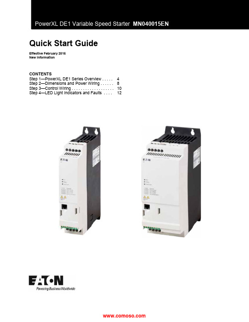
Quick Start GuideEffective February 2015New InformationCONTENTSStep 1—PowerXL DE1 Series Overview . . . . .4 Step 2—Dimensions and Power Wiring. . . . ..8 Step 3—Control Wiring.. . . . . . . . . . . . . . . . . .10 Step 4—LED Light Indicators and Faults. . . .12PowerXL DE1 VSS Quick Start GuideDisclaimer of Warranties and Limitation of LiabilityThe information, recommendations, descriptions, and safety notations in this document arebased on Eaton Electrical Inc. and/or Eaton Corporation’s (“Eaton”) experience and judgment,and may not cover all contingencies. If further information is required, an Eaton sales officeshould be consulted.Sale of the product shown in this literature is subject to the terms and conditions outlined inappropriate Eaton selling policies or other contractual agreement between Eaton and thepurchaser.THERE ARE NO UNDERSTANDINGS, AGREEMENTS, WARRANTIES, EXPRESSED ORIMPLIED, INCLUDING WARRANTIES OF FITNESS FOR A PARTICULAR PURPOSE OR MERCHANTABILITY, OTHER THAN THOSE SPECIFICALLY SET OUT IN ANY EXISTINGCONTRACT BETWEEN THE PARTIES. ANY SUCH CONTRACT STATES THE ENTIREOBLIGATION OF EATON. THE CONTENTS OF THIS DOCUMENT SHALL NOT BECOMEPART OF OR MODIFY ANY CONTRACT BETWEEN THE PARTIES. In no event will Eaton beresponsible to the purchaser or user in contract, in tort (including negligence), strict liability orotherwise for any special, indirect, incidental, or consequential damage or loss whatsoever,including but not limited to damage or loss of use of equipment, plant or power system, costof capital, loss of power, additional expenses in the use of existing power facilities, or claimsagainst the purchaser or user by its customers resulting from the use of the information,recommendations, and descriptions contained herein.The information contained in this manual is subject to change without notice.1PowerXL DE1 Series Variable Speed Starter MN040015EN–February PowerXL DE1 VSS Quick Start GuideSupport ServicesThe goal of Eaton is to ensure your greatest possible satisfaction with the operation of ourproducts. We are dedicated to providing fast, friendly, and accurate assistance. That is whywe offer you so many ways to get the support you need. Whether it’s by phone, fax, ore-mail, you can access Eaton’s support information 24 hours a day, seven days a week.Our wide range of services is listed below.You should contact your local distributor for product pricing, availability, ordering, expediting,and repairs.Web SiteUse the Eaton Web site to find product information. You can also find information on localdistributors or Eaton’s sales offices.Web Site Address/drivesEatonCare Customer Support CenterCall the EatonCare Support Center if you need assistance with placing an order, stockavailability or proof of shipment, expediting an existing order, emergency shipments, productprice information, returns other than warranty returns, and information on local distributors orsales offices.Voice: 877-ETN-CARE (386-2273) (8:00 a.m.–6:00 p.m. EST)FAX: 800-752-8602After-Hours Emergency: 800-543-7038(6:00 p.m.–8:00 a.m. EST)If you are in the U.S. or Canada, and have OI or PLC questions, you can take advantage of ourtoll-free line for technical assistance with hardware and software product selection, systemdesign and installation, and system debugging and diagnostics. Technical support engineersare available for calls during regular business hours.Drives Technical Resource CenterCall the low voltage Eaton Drives Technical Support Center should you need assistance with commissioning, trouble-shooting, parts identifications, or warranty issues.Voice: 877-ETN-CARE (386-2273),Option 2,Option 6, Option 3(8:00 a.m.–5:00 p.m. CST)e-mail:******************************PowerXL DE1 Series Variable Speed Starter MN040015EN–February 2PowerXL DE1 VSS Quick Start Guide3PowerXL DE1 Series Variable Speed Starter MN040015EN–February PowerXL DE1 VSS Quick Start GuidePowerXL DE1 Series Variable Speed Starter MN040015EN–February 4Step 1—PowerXL DE1 Series OverviewThis chapter describes the purpose and contents of this manual, the receiving inspection recommenda-tions, and the DE1 Series catalog numbering system.How to Use This ManualThe purpose of this manual is to provide you with information necessary to install, initial wiring, start up,troubleshoot, and maintain the Eaton DE1 Series. To provide for safe installation and operation of the equipment read the safety guidelines at the beginning of this manual and follow the procedures outlined in the following chapters before connecting power to the DE1Series VSS. Keep this operating manual handy and distribute to all users, technicians, and maintenance personnel for reference.If you need a full operational user manual please visit the Eaton website to obtain and download the full DE1 User Manual MN040011EN.Receiving and InspectionThe DE1 Series VSS has met a stringent series of factory quality requirements before shipment. It ispossible that packaging or equipment damage may have occurred during shipment. The DE1 series VSS is carefully packed and prepared for shipment. The devices should be shipped only in their original pack-aging with suitable packing materials. Please take note of the labels and instructions on the packaging as well as those used for unpacking. After receiving your DE1 Series VSS please check for the following:∙Before opening the package check the label info and make sure that you have received the correct DE1 VSS.∙Open the package with adequate tools and inspect the contents immediately after receipt in order to ensure that they are complete and undamaged.∙The packaging must contain the following parts:o A DE1 Variable Speed Startero An Instructional Leaflet IL040005ZUFigure 1. UnboxingPowerXL DE1 VSS Quick Start Guide5PowerXL DE1 Series Variable Speed Starter MN040015EN–February Rating LabelThe DE1 has device specific rated operation data and is listed on the nameplate on the right side of the device.The nameplate on top (Figure 4) is a simplified version that can be used to clearly identify the device if the main nameplate (Figure 3) is blocked by other devices.Figure 2. Nameplate ViewFigure 3. Nameplate A (Side Label)Figure 4. Nameplate B (Top Label)PowerXL DE1 VSS Quick Start GuideRating Label DescriptionTable 1. Label DescriptionPowerXL DE1 Series Variable Speed Starter MN040015EN–February 6PowerXL DE1 VSS Quick Start GuideCatalog DesignationThe catalog number selection/part number for DE1 VSS is subdivided into three groups.Series–Power Section–Model–(Versions)The following figure shows this in greater detail:7PowerXL DE1 Series Variable Speed Starter MN040015EN–February PowerXL DE1 VSS Quick Start GuidePowerXL DE1 Series Variable Speed Starter MN040015EN–February 8Step 2–Dimensions and Power WiringDimensions Series Frame a [in]a1 [in] b [in]b1 [in] c [in]R1 [in]R2 [in]Size (mm)(mm)(mm)(mm)(mm)(mm)(mm)DE1FS1 1.770.989.068.66 6.610.20.39(45)(25)(230)(220)(168)(5.1)(10)DE1FS2 3.54 1.979.068.66 6.610.20.39(90)(50)(230)(220)(168)(5.1)(10)Power WiringSeries Frame Line &Motor [AWG]Ground [AWG]Torque [in-lb]Size (mm 2)(Nm)DE1FS1 & FS218-618-615.051-61-6(1.7)Figure 6. DE1 Dimension ViewTable 2. DE1 DimensionsTable 3. Power Wire SizingPowerXL DE1 VSS Quick Start Guide9PowerXL DE1 Series Variable Speed Starter MN040015EN–February Power Connection ExamplesFigure 7. Power ConnectionsPowerXL DE1 VSS Quick Start GuidePowerXL DE1 Series Variable Speed Starter MN040015EN–February 10Step 3–Control WiringNote : The configurable inputs are only configurable by using the Extension Parameter Set Module (Part:DXE-EXT-SET), the Remote Keypad LED (Part: DX-KEY-LED), or the PC DrivesConnect software tool through a connection via the PowerXL Micro-Drive RJ45 to USB PC Cable (Part: DX-CBL-PC-3M0).These would need to be ordered in addition to the DE1 VSS as these are optional accessories.For the configurable mode of operations and setup of the accessories please see the DE1 User Manual MN040011EN.Figure 8.Control Terminal LayoutFigure 9. Control Terminal FunctionsPowerXL DE1 VSS Quick Start Guide11PowerXL DE1 Series Variable Speed Starter MN040015EN–February Figure 10. Default Wiring (without internal suppression filter)Figure 11. Default Wiring (with internal suppression filter)PowerXL DE1 VSS Quick Start GuidePowerXL DE1 Series Variable Speed Starter MN040015EN–February 12Step 4–LED Light Indicators and FaultsThe Run ,Status , and Fault Code LEDs will behave as follows:Run LED –Operation Signal (GREEN):∙Flashes every 2 seconds when the main voltage is applied, there is no enable input signal present at DI1 or DI2, and there are no active fault messages ∙Solid/continuous when the device is running and there is an input enable (start)signal on DI1or DI2∙No illumination when the main power is removed or there is an internal device faultStatus LED –Status Message (RED):∙Flashes with the Fault Code LED when there is an undervoltage condition ∙Solid/continuous illumination with Fault Code LED in the event of an internal communicationfault (DE1 malfunctioning)Fault Code LED –Fault Signal (RED/YELLOW):∙Cyclical Red flashing/pulse sequence with 2 second pauses observe Table 4∙Flashes Red with the Status LED when there is an undervoltage condition ∙Solid/continuous Red illumination with Status LED in the event of an internal communication fault (DE1 malfunctioning)∙Solid/continuous Yellow when DE1 VSS DC braking is activeFigure 12. LED Status Light LayoutPowerXL DE1 VSS Quick Start Guide13PowerXL DE1 Series Variable Speed Starter MN040015EN–February If the DE1 VSS has an internal communication fault (CPU fault), the green Run LED will turn off and the Status and Fault Code LEDs will both illuminate to a solid/continuous red status.NOTE : If this occurs the DE1 is faulty and will need to be replaced.Fault Messages can be reset by:∙Switching off the main voltage supply and switching it back on (cycling power)∙Switching off (removing)the input enable signal (DI1 or DI2) and switching it back onTable 4. Fault Code LED fault messagesPowerXL DE1 VSS Quick Start GuideAdditional HelpIn the US or Canada: please contact the Technical Resource Center at 1-877-ETN-CARE or 1-877-326-2273.All other supporting documentation is located on the Eaton web site atEaton1000 Eaton Boulevard Cleveland, OH 44122 USA © 2015EatonAll Rights ReservedPrinted in USAPublication No.MN040015EN February 2015Eaton is a registered trademark of Eaton Corporation.All other trademarks are property of their respective owners。
zollaedpro除颤仪操作指南
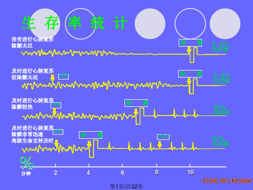
第27页/共32页
手动除颤
要从手动除颤模式转回自动除颤模式,按 住右侧功能软键,直到提示释放按钮,便 可转换回自动模式
第28页/共32页
心电监测
操作步骤
安装电池 连接3导心电电缆 贴上并连接好心电电极片 开机后,自动采用II导联监护,自动调节幅度 具有室颤报警提示功能
保持病人呼吸道的畅通是早 期急救的首要要素。
只要将机盖平放在 地面上,当作病人 的肩垫,既可自然 保持病人呼吸道的 畅通。
第3页/共32页
心肺复苏ABCD:循环
“检查循环状况”:
及早实施心肺复 苏可防止室颤恶化到 心室停搏,增加除颤 的成功率,有利于心 脑功能的保护,提高 生存率。
第4页/共32页
显示勾号,表示可以正常使用,反之显示叉号; 使用可充电电池时,前3次充电12小时,然后在监护状态
下,将其电放完,激活电池;
第30页/共32页
第31页/共32页
感谢您的欣赏!
第32页/共32页
生存链一:早期呼救
“保持镇静,检查病人反 应”:
当意外事件发生时,成 功急救的开始需要操作者保 持清晰的头脑、按部就班地 完成抢救过程。
“呼叫援助”:
及早呼救,让高级心血 管生命支持及时到达急救现 场,对提高病人的生存率具 有重要作用。
第2页/共32页
心肺复苏ABCD:气道及呼吸
“开放气道,检查呼吸, 进行二次人工呼吸”:
第6页/共32页
生存链二:除颤-粘贴电极
红“十”字标记 “–” 线: 与乳头对齐 “|” 线:与前胸骨中心 对齐 自然粘贴电极片 如果病人体形较魁梧或 较矮小,拔出红色电极 栓,底端电极片即可移 动,粘贴在心尖位置。
