rfc1868.ARP Extension - UNARP
实验指导书--英文

Zaozhuang University College of Information Science and EngineeringExperiment InstructorCourse: Computer NetworkTeacher:Wang XiaMajor:Computer Science and Technology& Network Engineering2012-9-4Lab1: using Ethereal to analyze DDL protocols In this lab, we’ll investigate the Ethernet protocol and the ARP protocol. Before beginning this lab, you’ll probably want to review sections 3.4 (Ethernet), and 4.2 (ARP) in the text. RFC 826 (ftp:///innotes/std/std37.txt) contains the gory details of the ARP protocol, which is used by an IP device to determine the IP address of a remote interface whose Ethernet address is known.1. Capturing and analyzing Ethernet framesLet’s begin by capturing a set of Ethernet f rames to study. Do the following:1.First, make sure your browser’s cache is empty.2.Start up the Ethereal packet sniffer3.Enter the following URL into your browser/ethereal-labs/ HTTP-ethereal-lab-file3.html.4.Stop Ethereal packet capture. First, find the packet numbers (the leftmost column in the upper Ethereal window) of the HTTP GET message that was sentyou're your computer to , as well as the beginning of the HTTP response message sent to your computer by . You should see a screen that looks something like this (where packet 10 in the screen shot below contains the HTTP GET message)5.Since this lab is about Ethernet and ARP, we’re not interested in IP or higherlayer protocols. So let’s change Ethereal’s “listing of captured packets” window so that it shows information only about protocols below IP. To have Ethereal do this, select Analyze->Enabled Protocols. Then uncheck the IP box and select OK.You should now see an Ethereal window that looks like:In order to answer the following questions, you’ll need tolook into the packet details and packet contents windows (the middle and lower display windows in Ethereal).Select the Ethernet frame containing the HTTP GET message. Expand the Ethernet II information in the packet details window. Note that the contents of the Ethernet frame (header as well as payload) are displayed in the packet contents window.Answer the following questions, based on the contents of the Ethernet frame containing the HTTP GET message. Whenever possible, when answering a question you should hand in a printout of the packet(s) within the trace that you used to answer the question asked. Annotate the printout to explain your answer. To print a packet, use File->Print, choose Selected packet only, choose Packet summary line, and select the minimum amount of packet detail that you need to answer the question.1. What is the 48-bit Ethernet address of your computer?2. What is the 48-bit destination address in the Ethernet frame? Is this the Ethernet address of ? (Hint: the answer is no). What device has this as its Ethernet address? [Note: this is an important question, and one that students sometimes get wrong. Re-read pages 450-451 in the text and make sure you understand the answer here.]3. Give the hexadecimal value for the two-byte Frame type field. What do thebit(s) whose value is 1 mean within the flag field?4. How many bytes from the very start of the Ethernet frame does the ASCII “G” in “GET” appe ar in the Ethernet frame?5. What is the hexadecimal value of the CRC field in this Ethernet frame?Next, answer the following questions, based on the contents of the Ethernet frame containing the first byte of the HTTP response message.6. What is the value of the Ethernet source address? Is this the address of your computer, or of (Hint: the answer is no). What device has this as itsEthernet address?7. What is the destination address in the Ethernet frame? Is this the Ethernet addressof your computer?8. Give the hexadecimal value for the two-byte Frame type field. What do thebit(s) whose value is 1 mean within the flag field?9. How many bytes from the very start of the Ethernet frame does the ASCII “O” in “OK” (i.e., the HTTP respo nse code) appear in the Ethernet frame?10. What is the hexadecimal value of the CRC field in this Ethernet frame?2. The Address Resolution ProtocolIn this section, we’ll observe the ARP protocol in action. We strongly recommend that you re-read section 5.4.2 in the text before proceeding.ARP CachingRecall that the ARP protocol typically maintains a cache of IP-to-Ethernet address translation pairs on your comnputer The arp command is used to view and manipulate the contents of this cache. Since the arp command and the ARP protocol have the same name, it’s understandably easy to confuse them. But keep in mind that they are different - the arp command is used to view and manipulate the ARP cache contents, while the ARP protocol defines the format and meaning of the messages sent and received, and defines the actions taken on message transmission and receipt. Let’s take a look at the contents of the ARP cache on your computer:MS-DOS. The arp command is in c:\windows\system32, so type either “arp” or “c:\windows\system32\arp” in the MS-DOS command line (without quotation marks).The arp command with no arguments will display the contents of the ARP cache on your computer. Run the arp command.11. Write down the contents of your computer’s ARP cache. What is the meaning of each column value?In order to observe your computer sending and receiving ARP messages, we’ll need to clear the ARP cache, since otherwise your computer is likely to find a needed IP-Ethernet address translation pair in its cache and consequently not need to send out an ARP message.MS-DOS. The MS-DOS arp –d * command will clear your ARP cache. The –d flag indicates a deletion operation, and the * is the wildcard that says to delete all table entries.Observing ARP in actionDo the following:1.Clear your ARP cache, as described above.2.Next, make sure your browser’s cache is empty.3.Start up the Ethereal packet sniffer4.Enter the following URL into your browser/ethereal-labs/ HTTP-ethereal-lab-file3.html5.Stop Et hereal packet capture. Again, we’re not interested in IP or higher-layer protocols, so change Ethereal’s “listing of captured packets” window so that it showsinformation only about protocols below IP. To have Ethereal do this, select Analyze->Enabled Protocols. Then uncheck the IP box and select OK. You should now see an Ethereal window that looks lik:In the example above, the first two frames in the trace contain ARP messages (as does the 6th message).Answer the following questions:12. What are the hexadecimal values for the source and destination addresses in the Ethernet frame containing the ARP request message?13. Give the hexadecimal value for the two-byte Ethernet Frame type field. What do the bit(s) whose value is 1 mean within the flag field?14. Download the ARP specification from ftp:///innotes/std/std37.txt. A readable, detailed discussion of ARP is also at/users/gorry/course/inet-pages/arp.html.a) How many bytes from the very beginning of the Ethernet frame does theARP opcode field begin?b) What is the value of the opcode field within the ARP-payload part of theEthernet frame in which an ARP request is made?c) Does the ARP message contain the IP address of the sender?d) Where in the ARP req uest does the “question” appear – the Ethernetaddress of the machine whose corresponding IP address is being queried?15. Now find the ARP reply that was sent in response to the ARP request.a) How many bytes from the very beginning of the Ethernet frame does theARP opcode field begin?b) What is the value of the opcode field within the ARP-payload part of theEthernet frame in which an ARP response is made?c) Where in the ARP message does the “answer” to the earlier ARP requestappear – the IP address of the machine having the Ethernet address whosecorresponding IP address is being queried?16. What are the hexadecimal values for the source and destination addresses in the Ethernet frame containing the ARP reply message?17. Open the ethernet--ethereal-trace- trace file inttp:///ethereallabs/ethereal-traces.zip. The first and second ARP packets in this trace correspond to an ARP request sent by the computer running Ethereal, and the ARP reply sent to the computer running Ethereal by the computer with the ARP-requested Ethernet address. But there is yet another computer on this network, as indiated by packet 6 – another ARP request. Why is there no ARP reply (sent in response to the ARP request in packet 6) in the packet trace?Extra CreditEX-1. The arp command:arp -s InetAddr EtherAddrallows you to manually add an entry to the ARP cache that resolves the IP address InetAddr to the physical address EtherAddr. What would happen if, when you manually added an entry, you entered the correct IP address, but the wrong Ethernet address for that remote interface?EX-2. What is the default amount of time that an entry remains in your ARP cache before being removed. You can determine this empirically (by monitoring the cache contents) or by looking this up in your operation system documentation. Indicate how/where you determined this value.Lab2: using Ethereal to analyze IPIn this lab, we’ll investigate the IP protocol, focusing on the IP datagram. We’ll do so by analyzing a trace of IP datagrams sent and received by an execution of the traceroute program (the traceroute program itself is explored in more detail in the Ethereal ICMP lab). We’ll investigate the various fields in the IP datagram, and study IP fragmentation in detail.1. Capturing packets from an execution of tracerouteIn order to generate a trace of IP datagrams for this lab, we’ll use the traceroute program to send datagrams of different sizes towards some destination, X. Recall that traceroute operates by first sending one or more datagrams with the time-to-live (TTL) field in the IP header set to 1; it then sends a series of one or more datagrams towards the same destination with a TTL value of 2; it then sends a series of datagrams towards the same destination with a TTL value of 3; and so on. Recall that a router must decrement the TTL in each received datagram by 1 (actually, RFC 791 says that the router must decrement the TTL by at least one). If the TTL reaches 0, the router returns an ICMP message (type 11 – TTL-exceeded) to the sending host. As a resultof this behavior, a datagram with a TTL of 1 (sent by the host executing traceroute) will cause the router one hop away from the sender to send an ICMP TTL-exceeded message back to the sender; the datagram sent with a TTL of 2 will cause the router two hops away to send an ICMP message back to the sender; the datagram sent with a TTL of 3 will cause the router three hops away to send an ICMP message back to the sender; and so on. In this manner, the host executing traceroute can learn the identities of the routers between itself and destination X by looking at the source IP addresses in the datagrams containing the ICMP TTL-exceeded messages.We’ll want to run traceroute and have it send datagrams of various lengths.Windows. The tracert program (used for our ICMP Ethereal lab) provided with Windows does not allow one to change the size of the ICMP echo request (ping) message sent by the tracert program. A nicer Windows traceroute program is pingplotter, available both in free version and shareware versions at. Download and install pingplotter, and test it out by performing a few traceroutes to your favorite sites. The size of the ICMP echo request message can be explicitly set in pingplotter by selecting the menu itemEdit->Advanced Options->Packet Options and then filling in the Packet Size field. The default packet size is 56 bytes. Once pingplotter has sent a series of packets with the increasing TTL values, it restarts the sending process again with a TTL of 1, after waiting Trace Interval amount of time. The value of Trace Interval and the number of intervals can be explicitly set in pingplotter.Do the following:1.Start up Ethereal and begin packet capture (Capture->Start) and then press OK on t he Ethereal Packet Capture Options screen (we’ll not need to select any options here).2.If you are using a Windows platform, start up pingplotter and enter the name ofa target destination in the “Address to Trace Window.” Enter 3 in the “# of times toTr ace” field, so you don’t gather too much data. Select the menu itemEdit->Advanced Options->Packet Options and enter a value of 56 in the Packet Size field and then press OK. Then press the Trace button. You should see a pingplotter window that looks something like this:Next, send a set of datagrams with a longer length, by selecting Edit->Advanced Options->Packet Options and enter a value of 2000 in the Packet Size field and then press OK. Then press the Resume button.Finally, send a set of datagrams with a longer length, by selectingEdit->Advanced Options->Packet Options and enter a value of 3500 in the Packet Size field and then press OK. Then press the Resume button.Stop Ethereal tracing.If you are unable to run Ethereal on a live network connection, you can download a packet trace file that was captured while following the steps above on one of the author’s Windows computers. You may well find it valuable to download this trace even if you’ve captured your own trace and use it, as well as your own trace, when you explore the questions below.2. A look at the captured traceIn your trace, you should be able to see the series of ICMP Echo Request (in the case of Windows machine) or the UDP segment (in the case of Unix) sent by your computer and the ICMP TTL-exceeded messages returned to your computer by the intermediate routers. In the questions below, we’ll assume you are using a Windows machine; the corresponding questions for the case of a Unix machine should be clear. Whenever possible, when answering a question you should hand in a printout of the packet(s) within the trace that you used to answer the question asked. Annotate the printout to explain your answer. To print a packet, use File->Print, choose Selected packet only, choose Packet summary line, and select the minimum amount of packet detail that you need to answer the question.1. Select the first ICMP Echo Request message sent by your computer, and expand the Internet Protocol part of the packet in the packet details window.What is the IP address of your computer?2. Within the IP packet header, what is the value in the upper layer protocol field?3. How many bytes are in the IP header? How many bytes are in the payload of the IP datagram? Explain how you determined the number of payload bytes.4. Has this IP datagram been fragmented? Explain how you determined whether or not the datagram has been fragmented.Next, sort the traced packets according to IP source address by clicking on the Source column header; a small downward pointing arrow should appear next to the word Source. If the arrow points up, click on the Source column header again. Select the first ICMP Echo Request message sent by your computer, and expand the Internet Protocol portion in the “details of selected packet header” window. In the “listing of captured packets” window, you should see all of the subsequent ICMP messages (perhaps with additional interspersed packets sent my other protocols running on your computer) below this first ICMP. Use the down arrow to move through the ICMP messages sent by your computer.5. Which fields in the IP datagram always change from one datagram to the next within this series of ICMP messages sent by your computer?6. Which fields stay constant? Which of the fields must stay constant? Which fields must change? Why?7. Describe the pattern you see in the values in the Identification field of the IP DatagramNext (with the packets still sorted by source address) find the series of ICMP TTLexceeded replies sent to your computer by the nearest (first hop) router.8. What is the value in the Identification field and the TTL field?9. Do these values remain unchanged for all of the ICMP TTL-exceeded repliessent to your computer by the nearest (first hop) router? Why? FragmentationSort the packet listing according to time again by clicking on the Time column.10. Find the first ICMP Echo Request message that was sent by your computer after you changed the Packet Size in pingplotter to be 2000. Has that message been fragmented across more than one IP datagram? [Note: if you find your packet has not been fragmented, you should download the zip file/ethereal-labs/ethereal-traces.zip and extract theipethereal-trace-1packet trace. If your computer has an Ethernet interface, a packet size of 2000 should cause fragmentation.]11. Print out the first fragment of the fragmented IP datagram. What information in the IP header indicates that the datagram been fragmented? What information in the IP header indicates whether this is the first fragment versus a latter fragment? How long is this IP datagram?12. Print out the second fragment of the fragmented IP datagram. What information in the IP header indicates that this is not the first datagram fragment? Are the more fragments? How can you tell?13. What fields change in the IP header between the first and second fragment?Now find the first ICMP Echo Request message that was sent by your computer after you changed the Packet Size in pingplotter to be 3500.14. How many fragments were created from the original datagram?15. What fields change in the IP header among the fragments?Lab3: using Ethereal to analyze ICMPIn this lab, we’ll explore several aspects of the ICMP protocol:•ICMP messages generating by the Ping program;•ICMP messages generated by the Traceroute program;•the format and contents of an ICMP message.Before attacking this lab, you’re encouraged to review the ICMP material in the textbook.We present this lab in the context of the Microsoft Windows operating system.1. ICMP and PingLet’s begin our ICMP adventure by capturing the packets generated by the Ping program.You may recall that the Ping program is simple tool that allows anyone (for example, a network administrator) to verify if a host is live or not. The Ping program in the source host sends a packet to the target IP address; if the target is live, the Ping program in the target host responds by sending a packet back to the source host. As you might have guessed (given that this lab is about ICMP), both of these Ping packets are ICMP packets.Do the following:1.Let’s begin this adventure by opening the Windows Command Prompt application (which can be found in your Accessories folder).2.Start up the Ethereal packet sniffer, and begin Ethereal packet capture.3.The ping command is in c:\windows\system32, so type either “ping –n 10 hostname” or “c:\windows\system32\ping –n 10 hostname” in the MS-DOS command line (without quotation marks), where hostname is a host on another continent. If you’re outside of Asia, you may want to enter t.hk for the Web server at Hong Kong University of Science and Technology. The argument “-n 10” indicates that 10 ping messages should be sent. Then run the Ping program by typing return.4.When the Ping program terminates, stop the packet capture in Ethereal.At the end of the experiment, your Command Prompt Window should look something like Figure 1. In this example, the source ping program is in Massachusetts and the destination Ping program is in Hong Kong. From this window we see that the source ping program sent 10 query packets and received 10 responses. Note also that for each response, the source calculates the round-trip time (RTT), which for the 10 packets is on average 375 msec.Figure 1 Command Prompt window after entering Ping command.Figure 2 provides a screenshot of the Ethereal output, after “icmp” has been entered into the filter display window. Note that the packet listing shows 20 packets: the 10 Ping queries sent by the source and the 10 Ping responses received by the source. Also note that the source’s IP address is a private address (behind a NAT) of the form 192.168/12; the destination’s IP address is that of the Web server at HKUST. Now let’s zoom in on the first packet (sent by the client); in the figure below, the packet contents area provides information about this packet. We see that the IP datagram within this packet has protocol number 01, which is the protocol number for ICMP. This means that the payload of the IP datagram is an ICMP packet.Figure 2 Ethereal output for Ping program with Internet Protocol expanded.Figure 3 focuses on the same ICMP but has expanded the ICMP protocol information in the packet contents window. Observe that this ICMP packet is of Type 8 and Code 0 – a so-called ICMP “echo request” packet. (See Figure 4.21 of text.) Also note that this ICMP packet contains a checksum, an identifier, and a sequencenumber.Figure 3 Ethereal capture of ping packet with ICMP packet expanded.What to Hand In:You should hand in a screen shot of the Command Prompt window similar to Figure 1 above. Whenever possible, when answering a question below, you should hand in a printout of the packet(s) within the trace that you used to answer the question asked. Annotate the printout to explain your answer. To print a packet, use File->Print, choose Selected packet only, choose Packet summary line, and select the minimum amount of packet detail that you need to answer the question.You should answer the following questions:1. What is the IP address of your host? What is the IP address of the destination host?2. Why is it that an ICMP packet does not have source and destination port numbers?3. Examine one of the ping request packets sent by your host. What are the ICMP type and code numbers? What other fields does this ICMP packet have? How many bytes are the checksum, sequence number and identifier fields?4. Examine the corresponding ping reply packet. What are the ICMP type and code numbers? What other fields does this ICMP packet have? How many bytes are the checksum, sequence number and identifier fields?2. ICMP and TracerouteLet’s now continue our ICMP adventure by capturing the packets generated by the Traceroute program. You may recall that the Traceroute program can be used to figure out the path a packet takes from source to destination.Traceroute is implemented in different ways in Unix/Linux and in Windows. In Unix/Linux, the source sends a series of UDP packets to the target destination using an unlikely destination port number; in Windows, the source sends a series of ICMP packets to the target destination. For both operating systems, the program sends the first packet with TTL=1, the second packet with TTL=2, and so on. Recall that a router will decrement a packet’s TTL value a s the packet passes through the router. When a packet arrives at a router with TTL=1, the router sends an ICMP error packet back to the source. In the following, we’ll use the native Windows tracert program. A shareware version of a much nice Windows Traceroute program is pingplotter (). We’ll use pingplotter in our Ethereal IP lab since it provides additional functionality that we’ll need there.Do the following2:1.Let’s begin by opening the Windows Command Prompt application (which can be found in your Accessories folder).2.Start up the Ethereal packet sniffer, and begin Ethereal packet capture.3.The tracert command is in c:\windows\system32, so type either “tracert hostname” or “c:\windows\system32\tracert hostname” in the MS-DOS command line (without quotation marks), where hostname is a host on another continent.(Note that on a Windows machine, the command is “tracert” and not“traceroute”.) If you’re outside of Europe, you may want to enter www.inria.fr for the Web server at INRIA, a computer science research institute in France. Then run the Traceroute program bytyping return.3.When the Traceroute program terminates, stop packet capture in Ethereal.At the end of the experiment, your Command Prompt Window should look something like Figure 4. In this figure, the client Traceroute program is in Massachusetts and the target destination is in France. From this figure we see that for each TTL value, the source program sends three probe packets. Traceroute displays the RTTs for each of the probe packets, as well as the IP address (and possibly the name) of the router that returned the ICMP TTL-exceeded message.Figure 4 Command Prompt window displays the results of the Traceroute program.Figure 5 displays the Ethereal window for an ICMP packet returned by a router. Note that this ICMP error packet contains many more fields than the Ping ICMP messages.Figure 5 Ethereal window if ICMP fields expanded for one ICMP error packet.What to Hand In:For this part of the lab, you should hand in a screen shot of the Command Prompt window. Whenever possible, when answering a question below, you should hand in a printout of the packet(s) within the trace that you used to answer the question asked. Annotate the printout to explain your answer. To print a packet, use File->Print, choose Selected packet only, choose Packet summary line, and select the minimum amount of packet detail that you need to answer the question.Answer the following questions:5. What is the IP address of your host? What is the IP address of the target destination host?6. If ICMP sent UDP packets instead (as in Unix/Linux), would the IP protocol number still be 01 for the probe packets? If not, what would it be?7. Examine the ICMP echo packet in your screenshot. Is this different from the ICMP ping query packets in the first half of this lab? If yes, how so?8. Examine the ICMP error packet in your screenshot. It has more fields than the ICMP echo packet. What is included in those fields?9. Examine the last three ICMP packets received by the source host. How are these packets different from the ICMP error packets? Why are they different?10. Within the tracert measurements, is there a link whose delay is significantly longer than others? Refer to the screenshot in Figure 4, is there a link whose delay is significantly longer than others? On the basis of the router names, can you guess the location of the two routers on the end of this link?3. Extra CreditFor one of the programming assignments you created a UDP client ping program. This ping program, unlike the standard ping program, sends UDP probe packets rather than ICMP probe packets. Use the client program to send a UDP packet with an unusual destination port number to some live host. At the same time, use Ethereal to capture any response from the target host. Provide an Ethereal screenshot for the response as well as an analysis of the response.Lab4: using Ethereal to analyze TCPIn this lab, we’ll investigate the behavior of TCP in detail. We’ll do so by analyzing a trace of the TCP segments sent and received in transferring a 150KB file (containing the text of Lewis Carrol’s Alice’s Adventures in Wonderland) from your computer to a remote server. We’ll study TCP’s use of sequence an d acknowledgement numbers for providing reliable data transfer; we’ll see TCP’s congestion control algorithm – slow start and congestion avoidance – in action; and we’ll look at TCP’s receiver-advertised flow control mechanism. We’ll also briefly consider TCP connection setup and we’ll investigate the performance (throughput and round-trip time) of the TCP connection between your computer and the server.1. Capturing a bulk TCP transfer from your computer to a remote serverBefore beginning our exploration of TCP, we’ll need to use Ethereal to obtain a packet trace of the TCP transfer of a file from your computer to a remote server. You’ll do so by accessing a Web page that will allow you to enter the name of a file stored on your computer (which contains the ASCII text of Alice in Wonderland), and then transfer the file to a Web server using the HTTP POST method. We’re using the POST method rather than the GET method as we’d like to transfer a large amount of data from your computer to another computer. Of course, we’ll be running Ethereal during this time to obtain the trace of the TCP segments sent and received from your computer.Do the following:1.Start up your web browser. Go the/ethereal-labs/alice.txt and retrieve an ASCII copy of Alice in Wonderland. Store this file somewhere on your computer.2.Next go to /ethereal-labs/TCP-ethereal-file1.html.3.You should see a screen that looks like:。
srv6相关标准

SRv6(Segment Routing over IPv6)是一种基于IPv6网络的新型路由技术,它通过在IPv6数据包中添加一个24位的标签来标识不同的路径。
这种技术可以提高网络的可扩展性、灵活性和安全性。
以下是一些与SRv6相关的标准:1. RFC 8210:这是SRv6的基本规范,定义了SRv6的基本概念、操作和实现要求。
2. RFC 8365:这个文档描述了如何使用BGP-LS(Border Gateway Protocol - Link State)协议在IPv6网络中传播SRv6路由信息。
3. RFC 8402:这个文档描述了如何使用MP-BGP(Multiprotocol BGP)协议在IPv6网络中传播SRv6路由信息。
4. RFC 8415:这个文档描述了如何使用IS-IS(Intermediate System to Intermediate System)协议在IPv6网络中传播SRv6路由信息。
5. RFC 8475:这个文档描述了如何使用OSPF(Open Shortest Path First)协议在IPv6网络中传播SRv6路由信息。
6. RFC 8597:这个文档描述了如何使用BFD(Bidirectional Forwarding Detection)协议在IPv6网络中检测SRv6路径的状态。
7. RFC 8795:这个文档描述了如何使用LDP(Label Distribution Protocol)协议在IPv6网络中分发SRv6标签。
8. RFC 8879:这个文档描述了如何使用PCE(Path Computation Element)协议在IPv6网络中计算SRv6路径。
9. RFC 8915:这个文档描述了如何使用SDN(Software-Defined Networking)技术来实现SRv6网络。
10. RFC 9119:这个文档描述了如何使用SRv6技术来实现网络切片。
ARP欺骗动态检测防御系统

测。不足:将多个子网数据镜像到一个端口.所得数据量过大;路由器放置分散时.嗅探
机必须做相应的分散部署,不便集中操作。
欺骗形式
(1)单一生机欺骗 这一类欺骗主要是“网关欺骗“。主机×(攻击者)
申称自己为主机A,伪造出数据包不间断假冒网关,欺 骗网内其它主机.达到阻止被骗主机访问外部网络,甚 至截获数据包窃取信息的目的。 (2)全子阿轮询欺骗(固定MAc)
……………*÷……”’…{=‘!一}‘‘71一 …~一≈R;= t‘二。’二i?1t” 一。
;
分析路由器日志确定ARP欺骗源MAc
分析路由器ARP表确定ARP欺骗源MAc
i
在C∽o路由器中我们通过如下命令将系统日志记录
到日志服务器中:
ciSco(corlfig)#logging facnity 10cal3 //定义将一些错误信 息记录到日志服务器,MAC地址冲突就属于这一类 Cisco(con盘g)#logging∞urce—interface G蟾ab砒孔hemetl/1 /
ARP欺骗动态检测防御系统
文/陈文波李善玺
ARP欺骗
检测方法
在以太网中.一个主机要和另一个主机进行直接通
常见的ARP防御方法是通过咿、MAc用户端和网关处双向静态绑定来实现。此方案在
信,必须要知道目标主机的MAC地址。而MAC地址可 以通过地址解析协议(ARP)获得。ARP的基本功能就是
小规模网络内颇有成效,而在大规模网络中就存在不易部署、难管理,治标不治本等问 题。因此.我们总结出对付ARP攻击的最佳方法是找到攻击源头,见如下4种方法:
这类形式欺骗与第二种形式类似,轮询欺骗子网 内所有主机.不同的是,攻击者对每一个IP进行欺骗都 会使用随机产生的伪造MAc地址,以达到躲避检测的 目的。
arp欺骗的解决方案

arp欺骗的解决方案1.引言1.1 概述ARP欺骗是一种常见的网络攻击手段,攻击者利用ARP协议的漏洞,通过发送虚假的ARP响应帧来篡改目标主机的ARP缓存表,从而达到欺骗目标主机的目的。
这种攻击会给网络带来严重的安全风险,可能导致数据泄露、网络崩溃甚至入侵。
本文旨在探讨ARP欺骗的解决方案,以帮助用户更好地应对网络攻击。
文章将介绍两种主要的解决方案:使用静态ARP表和使用ARP防火墙。
这两种方案不仅可以帮助用户有效应对ARP欺骗攻击,还能提升网络的安全性和稳定性。
在介绍解决方案之前,我们先对ARP欺骗的原理和危害进行了解和分析。
通过深入理解ARP欺骗攻击的原理,我们能更好地认识到这种攻击对网络安全造成的威胁,进而更好地理解解决方案的重要性和必要性。
接下来,我们将详细介绍解决方案一:使用静态ARP表。
通过使用静态ARP表,用户可以手动将IP地址和MAC地址的映射关系设置为固定值,有效地防止ARP欺骗攻击。
我们将介绍如何正确配置和管理静态ARP 表,并探讨其优势和劣势。
然后,我们将讨论解决方案二:使用ARP防火墙。
ARP防火墙是一种软件或硬件设备,通过监测和过滤网络中的ARP请求和响应,可以检测和阻止恶意ARP欺骗行为。
我们将介绍ARP防火墙的原理和配置方法,以及其在网络安全方面的优势和不足之处。
最后,我们将对本文进行总结,并对所介绍的解决方案进行评价。
我们将从安全性、实用性和成本等方面对这两种解决方案进行评估,以帮助读者全面了解和选择适合自身需求的解决方案。
通过本文的阅读,读者将能够了解ARP欺骗攻击的危害,掌握两种常见的解决方案,并能根据自身的实际情况和需求选择适合的解决方案,提升网络的安全性和稳定性。
1.2 文章结构文章结构部分的内容可以描述文章的整体框架和组织方式,以及各部分的主要内容和目标。
具体内容可以参考以下示例:文章结构:本文主要分为以下几个部分:引言、正文和结论。
引言部分:在引言部分,我们将首先概述ARP欺骗的背景和现状,介绍该问题对计算机网络和信息安全的危害。
于命令 discusconfigurationlincludearp 的含义的描述

于命令discusconfigurationlincludearp 的含义的描述摘要:1.命令discusconfigurationlincludearp的含义2.命令的使用方法和参数解释3.命令在实际网络配置中的应用场景4.总结:命令discusconfigurationlincludearp的价值和实用性正文:在很多网络设备的配置和管理中,命令discusconfigurationlincludearp 发挥着重要作用。
这个命令主要用于将ARP(地址解析协议)缓存中的数据包括在内,以便在网络环境中实现更高效的数据传输和管理。
下面我们将详细解析这个命令的使用方法和具体应用场景。
**命令的使用方法和参数解释:**命令discusconfigurationlincludearp的基本语法如下:```command syntax: discusconfigurationlincludearp [<interface>]```其中,<interface>表示网络接口的名称。
例如,如果你想要在以太网接口上应用这个命令,可以输入如下命令:```discusconfigurationlincludearp ethernet 0/0/1```在这个命令中,还包括了一些可选的参数,如:- `all`:表示应用命令到所有接口。
- `arp`:仅在ARP缓存中包括数据。
- `neighbor`:仅在邻居缓存中包括数据。
- `static-route`:仅在静态路由缓存中包括数据。
- `rip`:仅在RIP(路由信息协议)缓存中包括数据。
**命令在实际网络配置中的应用场景:**在实际网络环境中,命令discusconfigurationlincludearp主要用于以下场景:1.优化网络性能:通过定期更新和刷新ARP缓存,减少网络中的ARP广播风暴,提高数据传输效率。
2.管理网络设备:通过查看和操作ARP、邻居、静态路由等缓存数据,方便网络管理员对网络设备进行监控和管理。
TCP-IP详解卷习题

TCP-IP详解卷习题1.1请计算最多有多少个A类、B类和C类网络号。
1.2用匿名FTP(见27.3节)从主机上获取文件nfnet/tatitic/count。
该文件包含在NSFNET网络上登记的国内和国外的网络数。
画一坐标系,横坐标代表年,纵坐标代表网络总数的对数值。
纵坐标的最大值是习题1.1的结果。
如果数据显示一个明显的趋势,请估计按照当前的编址体制推算,何时会用完所有的网络地址(3.10节讨论解决该难题的建议)。
1.3获取一份主机需求RFC拷贝[Braden1989a],阅读有关应用于TCP/IP协议族每一层的稳健性原则。
这个原则的参考对象是什么?1.4获取一份最新的赋值RFC 拷贝。
“quoteoftheday”协议的有名端口号是什么?哪个RFC 对该协议进行了定义?1.5如果你有一个接入TCP/IP互联网的主机帐号,它的主IP地址是多少?这台主机是否接入了Internet?它是多接口主机吗?1.6获取一份RFC1000的拷贝,了解RFC这个术语从何而来。
1.8用匿名FTP从主机处获取文件about-internic/information-about-the-internic。
2.1如果你的系统支持nettat(1)命令(参见3.9节),那么请用它确定系统上的接口及其MTU。
3.1环回地址必须是127.0.0.1吗?3.2在图3-6中指出有两个网络接口的路由器。
3.3子网号为16bit的A类地址与子网号为8bit的B类地址的子网掩码有什么不同?3.4阅读RFC1219[Tuchiya1991],学习分配子网号和主机号的有关推荐技术。
3.5子网掩码255.255.0.255是否对A类地址有效?3.6你认为为什么3.9小节中打印出来的环回接口的MTU要设置为1536?3.7TCP/IP协议族是基于一种数据报的网络技术,即IP层,其他的协议族则基于面向连接的网络技术。
阅读文献[Clark1988],找出数据报网络层提供的三个优点。
描述arp欺骗的原理及过程 -回复
描述arp欺骗的原理及过程-回复ARP欺骗(Address Resolution Protocol spoofing)是一种网络攻击技术,攻击者通过伪造或欺骗目标网络设备的ARP信息,实现对通信进行窃听、篡改和伪装等恶意操作。
本文将详细介绍ARP欺骗的原理及过程。
一、ARP协议的基本原理在深入了解ARP欺骗之前,我们先来了解一下ARP协议的基本原理。
ARP (地址解析协议)是一种用于解析IP地址与MAC地址之间关系的协议。
在TCP/IP网络中,数据在发送时使用的是IP地址,而以太网(Ethernet)则使用MAC地址进行寻址。
ARP协议的作用就是通过查询网络上的其他设备,获取指定IP地址对应的MAC地址,从而实现数据包的转发。
ARP协议的工作方式如下:1. 当源主机要发送数据包给目标主机时,首先检查本地的ARP缓存表(ARP cache),看目标主机的MAC地址是否已经缓存。
2. 如果ARP缓存表中不存在目标主机的MAC地址,源主机会发送一个ARP请求广播,询问其他主机谁知道目标主机的MAC地址。
3. 目标主机收到ARP请求后,会发送一个ARP响应,包含自己的MAC 地址。
4. 源主机收到ARP响应后,将目标主机的IP地址和对应的MAC地址存入ARP缓存表,并将数据包发送给目标主机。
二、ARP欺骗原理ARP欺骗就是攻击者利用ARP协议的工作原理,欺骗目标主机获取其MAC地址,从而干扰或中断正常的通信。
实现ARP欺骗的关键是通过伪造ARP响应,将攻击者自己的MAC地址告诉目标主机,使其将数据包发送给攻击者。
这样,攻击者就可以窃听、篡改或伪装网络通信。
ARP欺骗的主要类型包括:1. ARP请求响应欺骗:攻击者伪造一个含有目标主机IP地址和另一个MAC地址的ARP响应,发送给本地网络中的其他主机,使其错误地认为目标主机的MAC地址是伪造的MAC地址。
这样,其他主机发送的数据包将会被错误地发送给攻击者。
ARP 防护解决方案总结

先来说说ARP协议。
ARP,全称地址解析协议,它是用来将网络层的IP地址解析为链路层的物理地址的一种协议。
简单点说,就是通过ARP协议,我们的计算机能够知道其他计算机在网络中的位置。
不过,正因为ARP协议的这个特性,也让它成为了黑客们常用的攻击手段。
言归正传,下面我就来给大家详细介绍ARP防护解决方案。
一、ARP欺骗攻击的原理及危害ARP欺骗攻击,顾名思义,就是黑客通过伪造ARP响应包,欺骗目标主机或者网络设备的一种攻击方式。
攻击者伪造ARP响应包,将自己的MAC地址伪装成目标主机的MAC地址,从而使得目标主机将数据包发送给攻击者。
这样一来,攻击者就可以截获目标主机与其他设备之间的通信数据,甚至还可以篡改数据内容,达到攻击目的。
1.数据泄露:攻击者截获通信数据,可能导致敏感信息泄露。
2.网络中断:攻击者篡改数据内容,可能导致网络通信中断。
3.网络滥用:攻击者利用ARP欺骗,可以实现网络资源的非法占用,甚至进行网络攻击。
二、ARP防护解决方案1.采用静态ARP表静态ARP表,就是手动配置ARP表项,指定IP地址与MAC地址的映射关系。
这样一来,即使攻击者伪造ARP响应包,也无法修改静态ARP表项。
不过,这种方法适用于网络规模较小、设备较少的环境,对于大型网络来说,配置和管理静态ARP表项是一项艰巨的任务。
2.采用ARP欺骗防护设备(1)实时监测ARP请求和响应包。
(2)自动识别并阻断ARP欺骗攻击。
(3)记录攻击行为,便于后续调查。
3.采用安全策略(1)限制ARP请求的发送频率,防止ARP洪泛攻击。
(2)限制ARP响应包的传播范围,防止ARP欺骗攻击。
(3)对内网设备进行安全审计,防止内部攻击。
4.采用加密通信对于敏感数据,采用加密通信可以防止数据被截获和篡改。
目前常用的加密通信方式有SSL/TLS、IPSec等。
网络安全是一项长期而艰巨的任务,我们需要时刻保持警惕,不断提高自己的安全防护能力。
希望这篇文章能够给大家带来一些启发,让我们一起为网络安全保驾护航!注意事项:1.及时更新静态ARP表静态ARP表虽然安全,但管理起来挺头疼的。
ARP双向绑定

ARP(Address Resolution Protocol),即地址解析协议,具体来说就是将IP 地址解析为数据链路(数据链路层,位于OSI 模型的第二层)的MAC( Media Access Control )地址。
而ARP欺骗则会扰乱网络设备间的正常通信。
通过伪造IP地址和MAC地址实现ARP欺骗,对网络的正常传输和安全都是一个很严峻的考验。
目前知道的带有ARP欺骗功能的软件有“QQ第六感”、“网络执法官”、“P2P 终结者”、“网吧传奇杀手”等,这些软件中,有些是人为手工操作来破坏网络的,有些是作为病毒或者木马出现,使用者可能根本不知道它的存在,所以更加扩大了ARP攻击的杀伤力。
从影响网络连接通畅的方式来看,ARP欺骗有两种攻击可能,一种是对路由器ARP 表的欺骗;另一种是对内网电脑ARP表的欺骗,当然也可能两种攻击同时进行。
不管怎么样,欺骗发送后,电脑和路由器之间发送的数据可能就被送到错误的MAC地址上,从表面上来看,就是“上不了网”,“访问不了路由器”,“路由器死机了”,因为一重启路由器,ARP表会重建,如果ARP攻击不是一直存在,就会表现为网络正常,所以用户更加确定是路由器“死机”了,而不会想到其他原因。
为此,宽带路由器背了不少“黑锅”,但实际上应该ARP协议本身的问题。
下面我们来看看如何来防范ARP欺骗。
上面也已经说了,欺骗形式有欺骗路由器ARP表和欺骗电脑ARP两种,我们的防护当然也是两个方面的,首先在路由器上进行设置,来防止路由器的 ARP表被恶意的ARP数据包更改;其次,我们也会在电脑上进行一下设置,来防止电脑的ARP表受恶意更改。
两个方面的设置都是必须的,不然,如果您只设置了路由器的防止ARP欺骗功能而没有设置电脑,电脑被欺骗后就不会把数据包发送到路由器上,而是发送到一个错误的地方,当然无法上网和访问路由器了。
我司路由器上IP与MAC地址绑定的方式有两种模式,普通绑定与强制绑定。
TCPIP路由技术(卷一)第二版

Chapter 1. TCP/IP ReviewChapter 2. IPv6 Overview※IPv6 Addresses1. Address Representation128位的IPv6地址被分为8个16位的段,用16进制数值表示,形如:3ffe:1944:0100:000a:0000:00bc:2500:0d0b书写IPv6地址的规则:1.每个段的开头的0可以被省略,例如上面的IPv6地址可以被写为:3ffe:1944:100:a:0:bc:2500:d0b;2.单一连续的多个段的0,可以被简写为“::”。
例如:ff02:0000:0000:0000:0000:0000:0000:0005可以被简写为ff02::5(“::”在一个IPv6地址中只能存在一个,否则会出现混淆);3.掩码的规则是:3ffe:1944:100:a::/64以下是部分特殊的IPv6地址:默认路由:::/0;unspecified地址,在NDP中使用:::/1282. IPv6 Address TypesIPv6地址的三种类型:1.Unicast2.Anycast3.MulticastIPv6地址中不存在广播地址,取而代之的是"all nodes" multicast地址(FF02::1)。
Global Unicast Addresses全球唯一的unicast地址。
其格式为:该格式在RFC 3587中定义,废弃和简化了之前将IPv6 unicast地址分为Top Level Aggregator (TLA)、Next-Level Aggregator (NLA)和其它区域的老格式。
主机部分(Host Portion)被称为Interface ID,Subnet ID包括在网络部分(Network Portion)中,global IPv6地址的Interface ID部分在大多数情况下长度为64位,Subnet ID在大多数情况下是16位。
以太网的标准
4.1 业务节点接口 4.1.1 1000BASE-LX/100BASE-FX 接口
1000BASE-LX/100BASE-FX接口的测试方法见YD/T XXXX-2001《高端路由器设备检验方法》。 4.1.2 ATM 接口
ATM 155 520kbit/s电接口、155 520kbit/s光接口、622 080kbit/s光接口的测试方法见YD/T XXXX-2001《高端路由器设备检验方法》。 4.1.3 POS 接口
3 基于以太网技术的宽带接入网网络结构
1
×× ××××—×××× 基于以太网技术的宽带接入网网络结构见图1 。
管理网
A
核心网 社区服务器
计算机 1
局
用
侧
户
计算机 n
设
侧
备
设
用户驻地网 1
备
用户驻地网 n
SNI 基于以太网技术的宽带接入系统 UNI
图1 基于以太网技术的宽带接入网网络结构图 基于以太网技术的宽带接入系统由局侧设备和用户侧设备组成。在面向小区或商业用户的应用中, 局侧设备一般考虑放在小区内,用户侧设备一般位于居民楼内;或者局侧设备位于商业大楼内,而用户 侧设备位于楼层内。而对于其它区域密集型用户的接入,局侧设备和用户侧设备的放置根据具体情况而 定。 局侧设备与用户侧设备推荐采用星型拓扑,局侧设备与核心网设备之间的拓扑结构可以是星型,也 可以是环型。 局侧设备和用户侧设备的技术要求见YD/T 1160-2001。
gbt1762621999电磁兼容试验和测量技术静电放电抗扰度试验gbt1762631998电磁兼容试验和测量技术射频电磁场辐射抗扰度试验gbt1762641998电磁兼容试验和测量技术电快速瞬变脉冲群扰度试验gbt1762651999电磁兼容试验和测量技术浪涌冲击抗扰度试验gbt1762661998电磁兼容试验和测量技术射频场感应的传导骚扰抗扰度试验gbt1762681998电磁兼容试验和测量技术工频磁场扰度试验gb92541998信息技术设备的无线电骚扰限值和测量方法ydt11562001路由器测试规范高端路由器ydt11602001接入网技术要求基于以太网技术的宽带接入网rfc0791091981网间网协议iprfc0792091981互联网控制消息协议icmprfc0826111982以太网地址解析协议arprfc1075111988距离向量组播路由协议dvmrprfc1271111991远程网络监视管理信息库rfc1661071994点到点协议ppprfc2131031997动态主机配置协议dhcprfc2236111997网间网组管理协议igmprfc2328041998开放最短路径优先ospfv2rfc2362061998与协议无关的组播pimsmrfc2453111998路由信息协议ripv2rfc2865062000拨号用户的远程认证服务radiusrfc2866062000radius计费基于以太网技术的宽带接入网网络结构图基于以太网技术的宽带接入系统由局侧设备和用户侧设备组成
RFC2865中文文档

RFC 2865 RADIUS 中文翻译收藏Network Working Group C. Rigney Request for Comments: 2865 S. Willens Obsoletes: 2138 LivingstonCategory: Standards Track A. RubensMeritW. SimpsonDaydreamerJune 2000远程认证拨号用户服务(RADIUS)备忘录状态本文档描述了一种Internet社区的Internet标准跟踪协议,它需要进一步进行讨论和建议以得到改进。
请参考最新版的“Internet正式协议标准” (STD1)来获得本协议的标准化程度和状态。
本备忘录可以不受限制地传播。
版权说明Copyright (C) The Internet Society (2000). All Rights Reserved.IESG说明:本协议已经被广泛实现和使用,经验表明当本协议在一个大范围的系统中使用会降低性能和丢失数据。
部分原因是协议中没有提供拥塞控制的机制。
读者可以发现阅读本文对跟踪IETF组织的AAA工作组的工作进程有很大的帮助,AAA工作组可能会开发一个能够更好的解决扩展性和拥塞控制问题的成功的协议。
摘要本文描述了一个传输认证、授权和配置信息的协议。
这些信息在想要认证链路的网络接入服务器(Network Access Server)和共享的认证服务器务器之间传递。
实现说明本备忘录记录了RADIUS协议,RADIUS协议的早期版本使用的UDP端口是16 45,由于和"datametrics"服务冲突,官方为RADIUS协议分配了一个新的端口号1812。
Rigney, et al. Standards Track [Page 1]RFC 2865 RADIUS June 2000目录1. 简介 (3)1.1 描述文档的约定 (4)1.2 术语 (5)2. 操作 (5)2.1 挑战/回应 (7)2.2 使用PAP和CHAP互操作 (8)2.3 代理 (8)2.4 为什么使用UDP (11)2.5 重发提醒 (12)2.6 被证明是有害的心跳 (13)3. 报文格式 (13)4. 报文类型 (17)4.1 接入请求报文 (17)4.2 接入成功回应报文 (18)4.3 接入拒绝回应报文 (20)4.4 接入挑战报文 (21)5. 属性 (22)5.1 User-Name (26)5.2 User-Password (27)5.3 CHAP-Password (28)5.4 NAS-IP-Address (29)5.5 NAS-Port (30)5.6 Service-Type (31)5.7 Framed-Protocol (33)5.8 Framed-IP-Address (34)5.9 Framed-IP-Netmask (34)5.10 Framed-Routing (35)5.11 Filter-Id (36)5.12 Framed-MTU (37)5.13 Framed-Compression (37)5.14 Login-IP-Host (38)5.15 Login-Service (39)5.16 Login-TCP-Port (40)5.17 (unassigned) (41)5.18 Reply-Message (41)5.19 Callback-Number (42)5.20 Callback-Id (42)5.21 (unassigned) (43)5.22 Framed-Route (43)5.23 Framed-IPX-Network (44)5.24 State (45)5.25 Class (46)5.26 Vendor-Specific (47)5.27 Session-Timeout (48)5.28 Idle-Timeout (49)5.29 Termination-Action (49)Rigney, et al. Standards Track [Page 2] RFC 2865 RADIUS June 20005.30 Called-Station-Id (50)5.31 Calling-Station-Id (51)5.32 NAS-Identifier (52)5.33 Proxy-State (53)5.34 Login-LAT-Service (54)5.35 Login-LAT-Node (55)5.36 Login-LAT-Group (56)5.37 Framed-AppleTalk-Link (57)5.38 Framed-AppleTalk-Network (58)5.39 Framed-AppleTalk-Zone (58)5.40 CHAP-Challenge (59)5.41 NAS-Port-Type (60)5.42 Port-Limit (61)5.43 Login-LAT-Port (62)5.44 Table of Attributes (63)6. IANA注意事项 (64)6.1 术语定义 (64)6.2 推荐的注册策略 (65)7. 举例 (66)7.1 用户Telnet到指定主机上 (66)7.2 用户使用CHAP认证方式认证 (67)7.3 用户使用挑战-回应卡 (68)8. 安全事项 (71)9. 更新记录 (71)10. 参考文献 (73)11. 致谢 (74)12. AAA工作组主席地址 (74)13. 作者地址 (75)14. 版权声明 (76)1. 简介本文档废弃了RFC 2138 [1]。
rfc中常用的测试协议

rfc中常用的测试协议摘要:1.RFC 简介2.RFC 中常用的测试协议a.网络协议测试1.网络数据包抓取和分析2.网络仿真和测试工具b.应用层协议测试1.HTTP 和HTTPS 测试2.FTP 和FTPS 测试3.SMTP 和SMTPS 测试c.安全协议测试1.TLS 和SSL 测试2.IPsec 测试d.传输协议测试1.TCP 和UDP 测试e.无线网络协议测试1.802.11 无线网络测试正文:RFC(Request for Comments)是一个用于讨论和记录互联网协议的标准文档系列。
在RFC 中,有许多常用的测试协议,这些协议用于确保互联网协议在实际应用中能够正常工作。
本文将详细介绍这些测试协议。
首先,RFC 中包含了大量的网络协议测试。
网络数据包抓取和分析是网络协议测试的基础,这对于诊断网络问题和优化网络性能至关重要。
此外,网络仿真和测试工具也是必不可少的,例如,网络模拟器(如NS-3)和测试平台(如Ixia)可以帮助工程师在实验室环境中模拟实际网络状况,从而对协议进行更严格的测试。
其次,应用层协议测试在RFC 中也占据重要地位。
HTTP 和HTTPS 是Web 应用中最常用的协议,有许多测试工具可以对它们的性能和安全性进行测试,例如,JMeter 和Locust 等负载测试工具。
此外,FTP 和FTPS、SMTP 和SMTPS 等传输协议也是常用的测试对象。
在安全协议方面,RFC 中包含了TLS 和SSL、IPsec 等协议的测试方法。
这些协议对于保护互联网数据传输的安全至关重要,因此需要进行严格的测试以确保其性能和安全性。
传输协议方面,TCP 和UDP 是互联网中最常用的传输协议,它们的测试方法也是RFC 中的重要内容。
TCP 测试关注可靠性和流量控制等方面,而UDP 测试则更注重数据传输速率和丢包率等指标。
最后,无线网络协议测试在RFC 中也有一定的比重。
例如,802.11 无线网络测试是评估无线局域网性能的关键。
ARP协议解析地址解析协议的工作原理与缓存更新策略

ARP协议解析地址解析协议的工作原理与缓存更新策略ARP(Address Resolution Protocol)是一种网络协议,用于解析网络层IP地址与物理层MAC地址之间的映射关系。
它是实现互联网通信的重要组成部分,其工作原理和缓存更新策略对网络的正常运行具有重要意义。
一、ARP协议工作原理ARP协议主要包括四个步骤:发送ARP请求、接收并处理ARP请求、发送ARP响应、接收并处理ARP响应。
1. 发送ARP请求:当主机A要发送数据给主机B时,首先查询本地ARP缓存表,判断目标IP地址是否在其中。
如果找到对应的目标MAC地址,则直接发送数据帧;如果没有找到,主机A会发送ARP 请求广播到本地网络上,请求目标主机B回复其MAC地址。
2. 接收并处理ARP请求:在一个局域网中,所有的主机都会接收到ARP请求广播包。
主机B接收到ARP请求包后,会检查自己的IP 地址,如果与请求包中的目标IP地址匹配,则将自己的MAC地址发送给主机A。
3. 发送ARP响应:主机B根据主机A发送的ARP请求包中的源IP 地址,构建一个ARP响应包,其中包括自己的MAC地址,并发送给主机A。
4. 接收并处理ARP响应:主机A接收到主机B发回的ARP响应包,将其中的目标MAC地址与源IP地址建立映射关系,并存储在本地的ARP缓存表中,以便下次通信时直接使用。
二、ARP缓存更新策略由于网络中的主机数量众多,ARP协议的缓存表需要经常进行更新,以保持准确性和实效性。
以下是常用的缓存更新策略。
1. 主动更新:在主机A与主机B之间长时间没有通信时,主机A可以主动发送ARP请求包,验证主机B的MAC地址是否仍然有效。
如果没有得到响应或收到的响应中MAC地址已发生变化,则主动更新MAC地址。
2. 被动更新:主机A在接收到其他主机的ARP请求包时,如果发现缓存表中已存在相同的IP地址,但MAC地址已发生变化,则进行被动更新,将缓存表中的MAC地址更新为最新的。
IP防ARP欺骗配置

静态IP防ARP欺骗配置:一、启用arp-check的功能在全局配置模式下开启ARP-CHECK功能S2126G-2(config)#port-security arp-check二、启用anti-arp-spoofing功能S2126G-2(config-if)#anti-ARP-Spoofing ip 网关地址三、启用端口安全并手动绑定IP与MACS2126G-2(config)#int f 0/3 //进入接口3S2126G-2(config-if)#switchport port-security //启用端口安全S2126G-2(config-if)#switchport port-security mac-address 4444.4444.4444 ip-address 192.168.44.55 //在接口下绑定PC的IP与MACS2126G-2(config-if)# switchport port-security maximum 1 //设置此端口最多学习1个MAC 地址,那么此接口不会再去学习其它的MAC地址了。
注:若此接口增加PC。
必须在交换机的对应接口上将IP与MAC绑定一下。
例如:PC的IP:192.168.44.57 MAC:2222.2222.2222S2126G-2(config)#int f 0/3S2126G-2(config-if)#switchport port-security maximum 2 // 将最大学习MAC地址的值改设为2,否则将无法绑定新机器S2126G-2(config-if)#switchport port-security mac-address 2222.2222.2222 ip-address 192.168.44.57配置文件如下:Building configuration...Current configuration : 451 bytes!version 1.0!hostname S2126G-2vlan 1!port-security arp-checkinterface fastEthernet 0/3Anti-ARP-Spoofing ip 192.168.44.1switchport port-securityswitchport port-security maximum 2switchport port-security mac-address 4444.4444.4444 ip-address 192.168.44.55switchport port-security mac-address 2222.2222.2222 ip-address 192.168.44.57 !endSwitch#动态IP防ARP欺骗配置:一、启用arp-check的功能在全局配置模式下开启ARP-CHECK功能S2126G-2(config)#port-security arp-check二、启用DHCP中继S2126G-2(config)#service dhcpS2126G-2(config)#ip helper-address 192.168.44.5三、启用端口安全S2126G-2(config)#int f 0/3S2126G-2(config-if)#switchport port-security四、启用端口自动绑定功能S2126G-2(config-if)#service dhcp address-bind port配置文件如下:S2126G-2#sh ruSystem software version : 1.68 Build Apr 25 2007 ReleaseBuilding configuration...Current configuration : 195 bytes!version 1.0!hostname S2126G-2vlan 1!port-security arp-checkservice dhcpservice dhcp address-bind portip helper-address 192.168.44.5interface fastEthernet 0/5switchport port-security。
Cisco DSL路由器配置和故障排除指南-IRB的RFC1483桥接故障排除说明书

Cisco DSL路由器配置与故障排除指南-IRB的RFC1483桥接故障排除目录简介先决条件要求使用的组件规则第1层问题在Cisco DSL路由器的前面板的载波检测(CD)灯是开/关?您使用的ISP支持Alcatel芯片组的DSLAM吗 ?Cisco DSL路由器背面的DSL端口是否插入到DSL墙上插座?ATM接口是否处于administratively down状态?管脚引线是否是正确的?您是否有Cisco 827正确的电源?DSL 工作模式是否正确?电路是否被正确地测试/供应?第 2 层问题是否具有正确的 PVC 值 (VPI/VCI)?您能 ping 通默认网关吗?网桥端口是否处于转发状态?网桥表中是否有条目?与 Cisco 技术支持联系相关信息简介您数字用户线路DSL连接不能正常工作的原因有很多。
本文档旨在对故障原因进行排查并加以修复。
第一故障排除步骤将确定您的异步数字用户线路(ADSL)服务哪块层发生故障。
故障可能发生在三个层面。
第 1 层 - 与 ISP 数字用户线路接入复用器 (DSLAM) 的 DSL 物理连接q第2.1层- ATM连通性q第2.2层 — ATM点对点协议(PPPoA)、以太网点对点协议(PPPoE)、RFC1483桥接或qRFC1483路由第3层- IPq确定从那层开始故障排除的最简单的方法是发行命令show ip interfacebrief。
此命令的输出会根据您的配置而略有不同。
827-ESC#show ip interface briefInterface IP-Address OK? Method Status ProtocolATM0 unassigned YES manual up upATM0.1 unassigned YES unset up upEthernet0 10.10.10.1 YES manual up up如果ATM0和ATM0.1的状态启用,并且协议启用,请开始发现并解决问题在第2层。
常用标准Radius属性说明
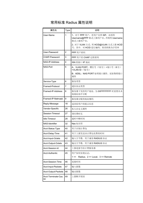
Service-Type
6
YES
YES
YES
YES
Framed-Protocol
7
YES
YES
YES
YES
当前标准协议没有能很好的区别PPPoE和VLAN,暂时都填成PPP
Framed-IP-Address
8
NO
YES
YES
YES
Framed-IP-Netmask
常用标准
属性名
Type
说明
User-Name
1
1、对于PPP用户,若用户名带ISP,该项用Username@PPP格式上报用户名;否则用Username格式上报用户名;
2、对于VLAN方式,用HCID@VLAN方式上报HCID号,其中,对HCID进行编码,将其转换为字符串
User-Password
2
Session-Timeout
27
预付费时长
Idle-Timeout
28
超时中断时间
NAS-Identifier
32
Nas标识符
Acct-Status-Type
40
用于识别计费包
Acct-Delay-Time
41
用于上报发送该计费包花费的时间
Acct-Input-Octets
42
输入字节数,用于兼容RADIUS协议
PPP用户密码
CHAP-Password
3
PPP用户的CHAP过程密码
NAS-IP-Address
4
ISN的接口IP地址
NAS-Port
5
A、VLAN PORT:槽位号(12位)+端口号(8位)+VLAN ID(12位)
ARP 防护解决方案总结
ARP 防护解决方案总结一、思科解决方案(接入层为思科三层交换机)1.1技术介绍1.1.1 DHCP SNOOPING采用DHCP管理的常见问题采用DHCP server可以自动为用户设置网络IP地址、掩码、网关、DNS、WI NS等网络参数,简化了用户网络设置,提高了管理效率。
但在DHCP管理使用上也存在着一些另网管人员比较问题,常见的有:1. DHCP server 的冒充。
2. DHCP server的DOS攻击。
3. 有些用户随便指定地址,造成网络地址冲突。
4. 由于DHCP 的运作机制,通常服务器和客户端没有认证机制,如果网络上存在多台DHCP服务器将会给网络照成混乱。
5. 由于不小心配置了DHCP服务器引起的网络混乱也非常常见。
黑客利用类似Goobler的工具可以发出大量带有不同源MAC地址的DHCP请求,直到DHCP服务器对应网段的所有地址被占用,此类攻击既可以造成DOS的破坏,也可和DHCP服务器欺诈结合将流量重指到意图进行流量截取的恶意节点。
DHCP服务器欺诈可能是故意的,也可能是无意启动DHCP服务器功能,恶意用户发放错误的IP地址、DNS服务器信息或默认网关信息,以此来实现流量的截取。
一个“不可靠”的DHCP服务器通常被用来与攻击者协作,对网络实施“中间人”M ITM(Man-In-The-Middle)攻击。
中间人攻击是一种攻击者利用正常的协议处理行为来更改两个终端之间的正常通信数据流而形成的一种攻击技术。
首先一个黑客会广播许多含有欺骗性MAC地址的DHCP请求(动态主机配置请求),从而耗尽合法DHCP服务器上的地址空间,一旦其空间地址被耗尽,这个“不可靠”的DHCP服务器就开始向“用户”的DHCP请求进行应答了,这些应答信息中将包括DNS服务器和一个默认网关的信息,这些信息就被用来实施一个MITM中间人攻击。
黑客也可以利用冒充的DHCP服务器,为用户分配一个经过修改的DNS Server,在用户毫无察觉的情况下被引导在预先配置好的假金融网站或电子商务网站,骗取用户帐户和密码,这种攻击是非常恶劣的。
免费ARP——精选推荐
免费ARP1. 免费ARP基本概念 免费ARP,也叫Gratutious ARP、⽆故ARP。
这种ARP不同于⼀般的ARP请求,它的Sender IP和Target IP字段是相同的,相当于是请求⾃⼰的IP地址对应的MAC地址。
发送免费ARP的主机或者设备,往往并不希望收到⼀个ARP应答。
因为若是收到了,说明⽹络上有⼈使⽤相同的IP,这会造成IP冲突。
免费ARP是⼀个⼴播ARP请求报⽂2. ⼀个Gratutious ARP报⽂ 从这个报⽂中可以看出,免费ARP是⼀个⼴播请求,且Serder IP和Target IP字段是相同的。
3. 哪些场景中可以出现免费ARP 主机/系统启动期间,进⾏⽹⼝/接⼝配置时产⽣; ⽹卡进⾏了某些配置变动,导致⽹⼝重新启动(如插拔⽹线,⾃动获取IP地址,⼿动更改IP地址、掩码、⽹关等参数)。
在实际研究过程中,win10系统的电脑⽹线插拔时,能出现免费ARP请求报⽂,但是win7的电脑同样操作,我未抓到免费ARP; 路由器等设备定期更新免费ARP,以防⽌不法者进⾏ARP欺骗(只能⼀定程度上防⽌)4. 免费ARP作⽤ 4.1 验证IP是否冲突 ⼀个主机可以这个免费ARP来确定同⼀个⽹络中,是否有其他设备使⽤了这个IP地址。
若是发送者收到⼀个回答,表⽰⽹络中存在与⾃⾝IP同样的主机;若是没有收到应答,则表⽰本机所使⽤的IP与⽹络中其他主机并不冲突。
4.2 双机热备 很多系统采⽤双机热备机制,⼀个为主设备,⼀个为从设备,两者MAC地址不同(设为MAC1和MAC2),但是通过某种软件,让其对外的IP是相同的(设为IP)。
正常情况下: 主设备正常⼯作,从设备空闲,⽹络中的客户机的ARP缓存条⽬为: MAC1--IP;但是当某个时刻主设备出故障,从设备就接管主设备的⼯作,且从设备⽴即⼴播免费ARP请求报⽂,让⽹络中的客户机及时更新ARP缓存表: MAC2--IP,这样客户机的业务不会收到影响 4.3 ⽹关定期刷新 这个主要是⽤在⽹关设备(如路由器)上。
动态ARP检测原理及应用
动态ARP检测原理及应用在一个局域网中,网络安全可以通过多种方式来实现,而采取DHCP snooping(DHCP防护)及DAI检测(ARP防护)这种技术,保护接入交换机的每个端口,可以让网络更加安全,更加稳定,尽可能的减小中毒范围,不因病毒或木马导致全网的瘫痪。
下面将详细的对这种技术的原理和应用做出解释。
一、相关原理及作用1、DHCP snooping原理DHCP Snooping技术是DHCP安全特性,通过建立和维护DHCP Snooping绑定表过滤不可信任的DHCP信息,这些信息是指来自不信任区域的DHCP信息。
DHCP Snooping绑定表包含不信任区域的用户MAC地址、IP地址、租用期、VLAN-ID 接口等信息。
当交换机开启了DHCP-Snooping后,会对DHCP报文进行“侦听”,并可以从接收到的DHCP Request或DHCP Ack报文中提取并记录IP地址和MAC地址信息。
另外,DHCP-Snooping允许将某个物理端口设置为信任端口或不信任端口。
信任端口可以正常接收并转发DHCP Offer报文,而不信任端口会将接收到的DHCP Offer报文丢弃。
这样,可以完成交换机对假冒DHCP Server的屏蔽作用,确保客户端从合法的DHCP Server获取IP地址。
2、DHCP snooping作用DHCP snooping的主要作用就是隔绝私接的DHCP server,防止网络因多个DHCPserver而产生震荡。
DHCP snooping与交换机DAI技术的配合,防止ARP病毒的传播。
建立并维护一张DHCP snooping的“绑定表”,这张表可以通过dhcp ack包中的ip和mac地址生成的,也可以通过手工指定。
它是后续DAI(Dynamic ARP Inspection)和IP Source Guard 基础。
这两种类似的技术,是通过这张表来判定ip或者mac地址是否合法,来限制用户连接到网络的。
- 1、下载文档前请自行甄别文档内容的完整性,平台不提供额外的编辑、内容补充、找答案等附加服务。
- 2、"仅部分预览"的文档,不可在线预览部分如存在完整性等问题,可反馈申请退款(可完整预览的文档不适用该条件!)。
- 3、如文档侵犯您的权益,请联系客服反馈,我们会尽快为您处理(人工客服工作时间:9:00-18:30)。
Network Working Group G. Malkin Request For Comments: 1868 Xylogics, Inc. Category: Experimental November 1995 ARP Extension - UNARPStatus of this MemoThis memo defines an Experimental Protocol for the Internetcommunity. This memo does not specify an Internet standard of anykind. Discussion and suggestions for improvement are requested.Distribution of this memo is unlimited.AbstractThe Address Resolution Protocol allows an IP node to determine thehardware (datalink) address of a neighboring node on a broadcastnetwork. The protocol depends on timers to age away old ARP entries. This document specifies a trivial modification to the ARP mechanism, not the packet format, which allows a node to announce that it isleaving the network and that all other nodes should modify their ARP tables accordingly.AcknowledgementsThanks to James Carlson/Xylogics for reviewing this document andproposing the backwards compatibility mechanism.1. IntroductionThe primary purpose of the Address Resolution Protocol, as defined in [1], is to determine a node’s hardware address based on its networkaddress (protocol address in ARPspeak). The ARP protocolspecifically states that nodes should not periodically advertisetheir existence for two reasons: first, this would generate a lot of network traffic and table maintenance overhead; second, it is highly unlikely that all nodes will need to communicate to all other nodes. Since a node does not advertise its existence, neither does itadvertise its imminent departure. This is not a serious problemsince most ARP implementations maintain timers to age away oldentries, and departing nodes seldom depart gracefully in any case.Over time, an additional use has been found for ARP: Proxy ARP.While there are those who believe Proxy ARP is an evil thing, it does serve a purpose; that is, it allows for communication in ways neverconsidered in the original IP architecture. For example, allowsdial-in hosts to connect to a network without consuming a largeMalkin Experimental [Page 1]amount of the IP address space (i.e., all of the hosts containaddresses on the same subnet, even though they are not directlyattached to the physical network associated with that subnet address. It is this use of Proxy ARP which produces the problem addressed bythis document.2. The ProblemConsider the following topology:+--------+| Host A |+--------+|======================================== LAN| |+--------+ +--------+| CS1 | comm. servers | CS2 |+--------+ +--------+| | | |+-+ +-+ +-+ +-+| | | | modems | | | |+-+ +-+ +-+ +-+Assume that all of the modems are on the same rotary; that is, when a remote host dials in, it may be assigned a modem on either of thecommunication servers. Further assume that all of the remote hosts’ IP addresses have the same subnet address as the servers and Host A, this in order to conserve address space.To begin, a remote host dials into CS1 and attempts to communicatewith Host A. Host A will assume, based on the subnet mask, that the remote host is actually attached to the LAN and will issue an ARPRequest to determine its hardware address. Naturally, the remotehost will not hear this request. CS1, knowing this, will respond in the remote host’s place with its own hardware address. Host A, onreceiving the ARP Reply, will then communicate with the remote host, transparently through CS1. So far everything is just fine.Now, the remote host disconnects and, before Host A can age its ARPcache, reconnects through CS2. Herein lies the problem. WheneverHost A attempts to send a packet to the remote host, it will send it to CS1 because it cannot know that its ARP cache entry is invalid.If, when the remote host disconnects, the server to which it wasattached could inform other nodes on the LAN that the protocoladdress/hardware address mapping was no longer valid, the problemwould not occur.Malkin Experimental [Page 2]3. The SolutionWhen a server, as described above, disconnects from a remote host for which it has responded to a Proxy ARP, it broadcasts an UNARP. AnUNARP is an unsolicited ARP Reply with the following field values:Hardware Address Space as appropriateProtocol Address Space 0x800 (IP)Hardware Address Length 0 (see Backwards Compatibility)Protocol Address Length 4 (length of an IP address)Opcode 2 (Reply)Source Hardware Address Not IncludedSource Protocol Address IP address of detaching hostTarget Hardware Address Not IncludedTarget Protocol Address 255.255.255.255 (IP broadcast)NOTE: this is a 16-byte packet (not including MAC header)On receiving an UNARP, a node deletes the ARP cache entry associated with the IP address.It is not strictly necessary that a server keep state informationabout whether or not it has actually sent a Proxy ARP Reply; it would be sufficient if a server always sends an UNARP when a remote hostdisconnects.Of course, there is no reason why a host which gracefully detachesfrom a LAN cannot also send an UNARP for itself. This would beespecially useful if, upon re-attaching, it might have a differenthardware address.4. Backwards CompatibilityThe modifications to support UNARP are trivial, so there is everyexpectation that it will be widely supported. Of course, there will be a period of time during which nodes which support UNARP willcoexist with nodes which do not support UNARP. To preventunenlightened nodes from adding spurious ARP cache entries withhardware addresses of zero, UNARP packets specify a hardware address length of zero. This should be rejected by nodes which do notsupport UNARP. As a consequence of this, the source and targethardware address fields do not exist in UNARP packets (as previously described).It is recommended that implementors include a configuration switch to disable UNARP in the event that some vendor’s ARP implementationmight take offense at the abbreviated UNARP packet format.Malkin Experimental [Page 3]5. Security ConsiderationsSecurity issues are not discussed in this memo.References[1] Plummer, D., "An Ethernet Address Resolution Protocol", STD 37,RFC 826, MIT, November 1982.Author’s AddressGary Scott MalkinXylogics, Inc.53 Third AvenueBurlington, MA 01803Phone: (617) 272-8140EMail: gmalkin@Malkin Experimental [Page 4]。
