通信原理Lecture 13 Bandpass Modulation and Demodulation_1
《通信原理》课件

在这份PPT课件中,我们将深入探讨通信原理的重要概念和技术。通过精美的 图片和易于理解的内容,帮助您全面了解通信系统的基本原理和调制解调技 术及其应用,以及信道编码、纠错编码和多址技术。
课程介绍
1 课程内容概述
探讨通信系统基本原理、调制解调技术、信道编码与纠错技术以及多址技术。
讨论传输介质的选择和不 同的编码技术对数据传输 的影响。
调制与解调技术
1 调制技术原理
介绍调制技术的基本原理,包括模拟调制和 数字调制。
2 调制方式与特点
比较不同调制方式的优缺点,包括调幅、调 频和调相。
3 解调技术原理
探讨解调技术的原理和实现方法,包括同步 技术和解调器的设计。
4 解调方法与应用
多址技术
1 多址技术基本原理
说明多址技术在实现多用户并行通信中的基 本原理和应用。
2 分时多址技术
介绍分时多址技术的工作原理和应用领域, 包括时分多址和码分多址。
运营商课程合作
我们的愿景
为运营商培养专业人才,提供 领先的通信技术培训和支持。
课程特色
由资深专家授课,结合实际案 例和实践经验,加深学生对通 信原理的理解。
合作机会
欢迎运营商与我们合作,共同 推进通信行业的发展。
总结
本PPT课件深入浅出地介绍了《通信原理》的关键概念和技术。希望通过这次 学习,您能够全面了解通信系统的原理和技术,并能够应用到实际工作中。
讨论不同场景下的解调方法和实际应用,如 调幅解调、调频解调和调相解调。
信道编码与纠错技术
1 信道编码原理
介绍信道编码的基本原理和作用,以及不同类型的编码方法。
2 奇偶校验及海明码
讲解奇偶校验和海明码的原理,以及如何通过纠错编码提高数据传输的可靠性。
第一章 绪论 通信原理课件

1.3 通信系统和通信网的构成
• 通信网模型(图1.2)
– 转接设备(交换设备):选择路由,将信息 从信源一站一站传递,直到到达信宿
– 信令、协议:为通信网中传送信息,必须符 合预先制定的规程,才能保证通信成功,这 样的规程叫信令(电话网)或协议(计算机 网)
2020/11/11
2020/11/11
1.2 通信发展简史和展望
• 远程和大容量化
– 有线:明线→同轴电缆→光纤 –无线:短波→微波→卫星
2020/11/11
1.2 通信发展简史和展望
• 网络和综合化
– PSTN:电路交换 – Internet:分组交换
2020/11/11
1.2 通信发展简史和展望
• 移动和个人化
• 一些概念
– 有效性:单位带宽内传送的信息量的多少。 模拟通信系统用单位带宽内能传送的电话或 电视路数表示;数字通信系统用频带利用率 (bit/Hz)表示
– 可靠性:接收信息的准确程度。模拟通信系 统用接收端的输出信噪比表示;数字通信系 统用误比特率表示
– 有效性和可靠性是相互矛盾的,可以互换。
2020/11/11
2020/11/11
1.2 通信发展简史和展望
• 通信的发展方向
– 数字化 – 远程与大容量化 – 网络与综合化 – 移动和个人化
2020/11/11
1.2 通信发展简史和展望
• 数字化
– 数字信息和模拟信息的区别:前者取值离散 ,后者取值离散
– 数字通信的主要优点
• 抗干扰能力强,且中继时无噪声积累 • 可使用现代数字信号处理技术进行处理 • 差错可以控制,传输质量好 • 易于加密 • 易于实现设备小型化
《通信原理讲稿》课件

通信技术在工业生产中的应用
工业自动化
无线传感器网络、工业以太网等技术实现生产过程中的设备监控与 控制。
物流管理
GPS、RFID等技术用于物流跟踪和运输管理,提高物流效率和准确 性。
远程控制
通过无线通信技术实现对工业设备的远程控制,降低维护成本和响应 时间。
通信技术的发展趋势与未来展望
5G技术
第五代移动通信技术将提供更高的数据传输速率、更低的延迟和 更大的网络容量,支持更多物联网设备的连接。
通过卫星传输数字信号,具有覆盖范围广、 传输距离远等优点。
无线传输
通过电磁波传输数字信号,如无线电波、微 波等。
网络传输
通过网络传输数字信号,具有灵活、方便、 高效等优点。
05
通信协议与标准
通信协议的组成与功能
通信协议的组成
通信协议由多个子协议组成,包括物 理层协议、数据链路层协议、网络层 协议、传输层协议和应用层协议等。
通信协议的功能
通信协议具有多种功能,包括建立通 信连接、管理数据传输、控制数据流 量、确保数据完整性和保密性等。
通信协议的分层结构
分层结构的概念
通信协议采用分层结构,每一层协议都有其特定的功能和职责,各层之间相互协作,共同实现整个通信协议的功 能。
分层结构的优点
分层结构具有多种优点,包括可维护性、可扩展性、可重用性和灵活性等。各层之间相互独立,降低了系统的复 杂性和耦合度,便于开发和维护。
损耗
信号在传输过程中减小的量,通常以分贝(dB )为单位。
信号在信道中的传
信号的调制和解调
将低频信号调制到高频载波上,以便在信道中传输,然后在接收 端解调。
信号的编码和解码
将信息编码成二进制格式,以便在信道中传输,然后在接收端解码 还原成原始信息。
通信原理讲义第一章

考核方式
第一章 绪论
《通信原理》的分数由平时成绩和考 试成绩两部分组成。
考试成绩即期末统一考试成绩占70%。
平时成绩占30%,上课随机点名三次 不到者,平时成绩不及格。
第一章 绪论
第一章 绪论
主要内容
§1.1 引言 §1.2 通信系统的组成 §1.3 通信系统分类及通信方式 §1.4 信息及其度量 §1.5 通信系统的主要性能指标 §1.6 通信技术的64 麦克斯韦尔 电磁辐射方程 1876 贝尔 电话 1896 马可尼 无线电报 1906 真空管 1918 调幅广播 超外差接收机 1925 三路明线载波电话 多路通信 1936 调频广播 1937 脉冲编码调制PCM 1938 电视广播 1940 二战刺激 雷达和微波系统
对于电子类专业学生,也是拓宽知识面,从而为一系列 相关学科(通信电子、自控、遥控遥测、仪表、家电、智能 楼宇等)的创造性工作奠定必要的信息科学背景基础。
§1.1 引言
第一章 绪论
一、什么是通信
(1)通信的通俗定义:
一点向另一点传递消息的过程
(2)通信的专业定义:
利用信号(电、光、声音或烟火、旗帜等)的某一个或几个参数 (如电波的振幅、频率、相位等)的变化承载信息,在特定物理 媒介(称“信道”)中传输、交换和处理的过程。
主要目的
1、学习通信原 理的意义; 2、明确通信理 论和技术的部分 主要概念; 3、串接通信理 论和技术的主要 知识框架。
第一章 绪论
为什么需要学习通信原理?
物质、能源、信息是人类生存的三大要素资源。
物质与能源:大学物理课程(基本性质与基本方法)
信息:通信原理课程论述了信息传输与处理的基本过程与方 法,是进一步掌握信息科学的必由之路。
通信原理讲义
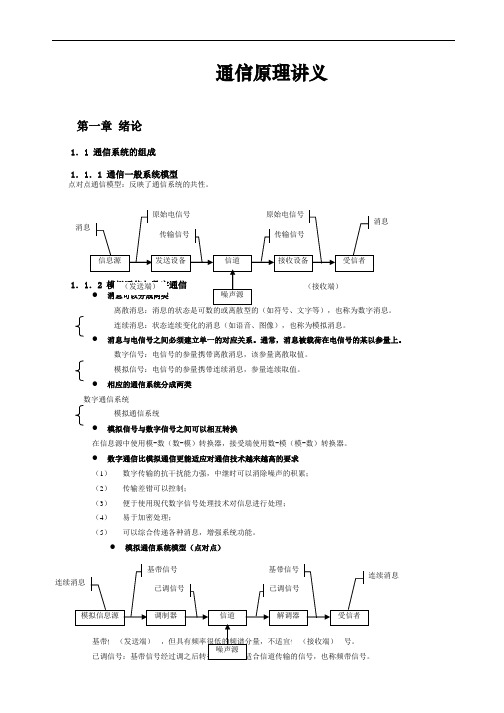
通信原理讲义第一章绪论1.1 通信系统的组成1.1.1 通信一般系统模型点对点通信模型:反映了通信系统的共性。
连续消息:状态连续变化的消息(如语音、图像),也称为模拟消息。
●消息与电信号之间必须建立单一的对应关系。
通常,消息被载荷在电信号的某以参量上。
数字信号:电信号的参量携带离散消息,该参量离散取值。
模拟信号:电信号的参量携带连续消息,参量连续取值。
●相应的通信系统分成两类数字通信系统模拟通信系统●模拟信号与数字信号之间可以相互转换在信息源中使用模-数(数-模)转换器,接受端使用数-模(模-数)转换器。
●数字通信比模拟通信更能适应对通信技术越来越高的要求(1)数字传输的抗干扰能力强,中继时可以消除噪声的积累;(2)传输差错可以控制;(3)便于使用现代数字信号处理技术对信息进行处理;(4)易于加密处理;(5)可以综合传递各种消息,增强系统功能。
●模拟通信系统模型(点对点)调制器:将基带信号转变为频带信号的设备。
解调器:将频带信号转变为基带信号的设备。
模拟通信强调变换的线性特性,既已调参量与基带信号成比例。
● 数字通信系统模型(点对点) 强调已调参量与基带信号之间的一一对应。
数字通信需要解决的问题:(2) 编码与解码:通过差错控制编码消除噪声或干扰造成的差错; (3) 加密和解密:对基带信号进行人为“搅乱”;(4) 同步:发送和接收节拍一致,包括:位同步(码元同步)和群同步、帧同步、句同步或码组同步。
数字通信模型:1.2 通信系统的分类及通信方式 1.2.1 通信系统分类● 按消息的物理特征分类电报通信系统 电话通信系统 数据通信系统图像通信系统 ● 按调制方式分类基带传输线性调制载波调制 非线性调制 频带传输 数字调制脉冲模拟调制脉冲调制消息 消息消息消息脉冲数字调制●按信号特征分类模拟通信系统数字通信系统●按传输媒介分类有线无线1.2.2 通信方式分类●点对点通信,按传送方向与时间关系:单工通信:消息只能单方向传输半双工通信:通信双方都能收发消息,但不能同时进行收发全双工通信:通信双方可同时进行收发●数字通信中,按数据信号码元排列方式:串行传输:数字信号码元序列按时间顺序一个接一个的在信道中传输,适合远距离传输。
通信原理PPT lecture11
△M系统的信号动态范围
正弦调制信号的振幅为Am 系统输出端SNR
2 m 2 max
So A 2 A 2 Am Som Am N qo N qo N qo Amax N qo Amax
2
2
信号的动态范围 ♦满足不过载条件的Amax ♦保证一定输出信噪比要求的Amin
接收端
数字电话系统帧结构
30/32路基群 RBP=fs×N×n=8000×32×8=2.048Mb/s
复帧 F0 F1 F2 F14 F15
TS0 TS1
TS16
TS31
偶帧 * 0 0 1 1 0 1 1 复帧 奇帧
* 0 1 A 1 1 1 1
数字电话系统帧结构
高次群
数字电话系统帧结构
x(kTs)
缓存器 编码器 解码器
y(kT s)
电平估 计器
ADPCM—自适应量化
AQB
x(kTs)
编码器 解码器
y(kT s)
电平估 计器
电平估 计器
语音和图像的压缩编码 无损压缩 有损压缩 CD和MP3
语音压缩编码
基音周期
语音生成模型
周期信号源 清音 Vn 随机噪声源 浊音 × 滤波器 xn
R 1 R 0 R 1 R 2 R 1 R 0 其中rxx ,Rxx R N 1 R N 2 R N
ADPCM—自适应量化
AQF
ADPCM—自适应预测
R 1 R 0 R 1 R 0 R 2 R 1 R N 1 R N 2 R N
北邮杨鸿文老师通信原理讲义-3

R=
H0 ( X ) − H∞ ( X ) H∞ ( X ) ,称此为冗余度或者相对剩余度。又称η = 为信源效率。 H0 ( X ) H0 ( X )
我们举例来说明这些结果的含义。设有一篇文章有 10 万汉字。假设汉字共有 8000 个, 则这篇文章表达成二进制需要 10 × log 2 8000 ≈ 162kByte ,但如果汉字的冗余度是 68%,
4
那么我们可以指望用大约 52kByte 来保存这篇文章。
1/1
<清北启航
>
1/1
<清北启航
>
<清北启航
北京邮电大学电信工程学院 《通信原理 II》
>
Lecture Notes-3-2005/02/28
一 信道的概念
指所研究问题中从发送端到接收端之间的一切环节。 不同的情 信道是一个抽象的概念, 景下, “发送端”和“接收端”所指不同,因而信道的含义也不同。例如在某个无线通信系 统中, 发送天线到接收天线之间的电波传遍空间是信道, 这个信道也叫狭义信道或者传输媒 质。调制器输出到解调器输入的一切环节是信道,这个信道也叫调制信道,它包含了上下变 频器、放大器、收发滤波器、收发天线、传输媒质等环节。从编码器的输出到译码器输入的 一切环节也是信道,这个信道叫编码信道,它包括了调制解调器以及调制信道。
1. 恒参信道与随参信道
如下图所示。 这里发送信号或者接收信号可能是模 发送信号经过信道成为了接收信号, 拟信号(时间连续、取值连续) ,也可能是数字信号(时间离散、取值可能连续或者离散) 。 注意取值连续的数字信号可以理解为进制数趋于无限的情形。
《通信原理说课》课件

05
通信协议与标准
通信协议概述
通信协议定义
通信协议是通信系统中的规则集 合,用于规范不同设备间的信息
传输和交换。
通信协议的作用
确保信息传输的可靠性和高效性 ,实现不同设备间的互操作性。
通信协议的组成
包括语法、语义和时序三个部分 。
常见通信协议标准
TCP/IP协议族
用于互联网通信的标准协议族,包括TCP、 UDP等。
理论与实践结合
课程注重理论与实践相结 合,通过实验和课程设计 等环节,提高学生实际操 作和解决问题的能力。
课程目标
知识目标
学生应掌握通信系统的基 本概念、原理、性能指标 及关键技术。
能力目标
培养学生分析、设计、优 化通信系统的能力,以及 实验操作和团队协作能力 。
素质目标
培养学生的创新意识、严 谨的科学态度和良好的职 业道德。
实验安排
每个实验2-3课时,共10个课时,分两周完成。
实验目的
通过实验,使学生掌握通信原理的基本概念和原 理,提高实际操作和解决问题的能力。
实践项目与要求
实践项目
设计并实现一个简单的通信系统,如无线传输系统或卫星通信系 统。
实践要求
学生需自行设计系统方案,完成硬件搭建和软件编程,并进行测试 和优化。
通信系统模型
发送端
负责将信息转换为可传输的信号 。
信道
传输信号的媒介,可以是无线电波 、光纤、电缆等。
接收端
负责将传输的信号还原为原始信息 。
03
信号处理基础
信号的时域与频域表示
总结词
信号的时域与频域表示是通信原理中的重要概念,它们分别描述了信号在不同 时间与频率上的特性。
通信原理Lecture 14 Bandpass Modulation and Demodulation_2
Lecture 14Bandpass Modulation and DemodulationDr. Xin Zhang School of Electronics and Information EngineeringSouth China University of TechnologyIntroductionReviews of Lecture 13Phasor representation of a sinusoidModulationPSK; ASK; FSK; Quadrature amplitude modulation (QAM) Signal detectionEquivalence theoremCorrelation receiverCoherent detection of PSKSampled match filterAssume that s1(t) was transmitted. Then the expectedvalues of the product integrators in Figure above, with reference signal ,are found as•4.4.1 Coherent Detection of PSK (2)•4.4.2 Sampled Matched Filter (2)Figure above shows how an MF can be implemented using digital hardware.•4.4.3 Coherent Detection of MPSKThe signal space for a multiple phase-shift keying (MPSK) signal set; the figure describes a four-level (4-ary) PSK or quadriphase shift keying (QPSK) example (M = 4).For typical coherent M -ary PSK (MPSK) systems, s i (t ) can be expressed asIf an orthonormal signal space is assumed in Equations(3.10) and (3.11), we can choose a convenient set of axes,such as•4.4.3 Coherent Detection of MPSK (2)Now s i (t ) can be written in terms of these orthonormal coordinates, givingIn practice, the implementation of an MPSKdemodulator is shown in follows Figure, requiring only N = 2 product integrators regardless of the size of the signal setM..•4.4.3 Coherent Detection of MPSK (3)The received signal •4.4.3 Coherent Detection of MPSK (4)There are only two reference waveforms or basisfunctions, for the upper correlator and for the lower correlator.The upper correlator computesThe lower correlator computesX is the inphase component of the received signal,Y is the quadrature component, is a noisy estimate of the transmitted •4.4.3 Coherent Detection of MPSK (5)The received phase angle can be accomplished by computing the arctan of Y/X .The demodulator computes for each of the prototypes and chooses the yielding the smallest output.•4.4.3 Coherent Detection of MPSK (6)•4.4.4 Coherent Detection of FSKFSK modulation is characterized by the information being contained in the frequency of the carrier.A typical set of FSK signal waveforms was described asAssuming that the basis functions , form an orthonormal set, the most useful form for isWe can write Therefore,The i th prototype signal vector is located on the i th coordinate axis at a displacement from the origin of the signal space. In this scheme, for the general M -ary case and a given E, the distance between any two prototype signal vectors s i and sjis constant:•4.4.4 Coherent Detection of FSK (2)•4.4.4 Coherent Detection of FSK (3)Partitioning the signal space for a 3-ary FSK signal.e.g. Received phase as a function of propagation delay4.5 NONCOHERENT DETECTION•4.5.1 Detection of Differential PSKThe name differential PSK(DPSK) sometimes needs clarification because two separate aspects of themodulation/demodulation format are being referred to: the encoding procedure and the detection procedure.The term differential encoding refers to the procedure of encoding the data differentially.The term differentially coherent detection of differentially encoded PSK, the usual meaning of DPSK, refers to adetection scheme often classified as noncoherent because itdoes not require a reference in phase with the received carrier.•4.5.1 Detection of Differential PSK(2)With noncoherent systems, no attempt is made to determine the actual value of the phase of the incoming signal.If the transmitted waveform isthe received signal can be characterized by4.5.1 Detection of Differential PSK(3)For coherent detection, matched filters (or their equivalents) are used.For noncoherent detection, this is not possible because the matched filter output is a function of the unknown angle .The carrier phase of the previous signaling interval can be used as a phase reference for demodulation. Its use requires differential encoding of the message sequence at the transmitter.•4.5.1 Detection of Differential PSK(4)To send the i th message (i = 1, 2, . . . , M), the present signal waveform must have its phase advanced by radians Array over the previous waveform.The detector, in general, calculates the coordinates of theincoming signal by correlating it with locally generatedwaveforms.The detector then measures the angle between the currentlyreceived signal vector and the previously received signal vector.•4.5.1 Detection of Differential PSK(5)In general, DPSK signaling performs less efficiently than PSK, because the errors in DPSK tend to propagate (to adjacent symbol times) due to the correlation betweensignaling waveforms.We might estimate that the error probability for DPSK is approximately two times (3 dB) worse than PSK; thisdegradation decreases rapidly with increasing signal-to-noise ratio.The trade-off for this performance loss is reduced system complexity.•4.5.2 Binary Differential PSK ExampleThe transmitted waveform must first be encoded in a differential fashion. Then the sequence of encoded bits c(k) can, in general, be encoded in one of two ways:•4.5.2 Binary Differential PSK Example (2)Figure above illustrates the binary DPSK detection scheme in block diagram form.The basic product integrator is the essence of the demodulator;as with coherent PSK, we are still attempting to correlate areceived signal with a reference.The interesting difference here is that the reference signal is simply a delayed version of the received signal.•4.5.2 Binary Differential PSK Example (3)It must be pointed out that the detector in Figure above is suboptimum in the sense of error performance.The optimum differential detector for DPSK requires a reference carrier in frequency but not necessarily inphase with the received carrier.Hence the optimum differential detector is shown in the follow Figure.•4.5.3 Noncoherent Detection of FSKA detector for the noncoherent detection of FSKwaveforms can be implemented with correlators.However, the hardware must be configured as an energy detector, without exploiting phase measurements. For this reason, the noncoherent detector typically requires twice as many channel branches as the coherent detector. The follow Figure illustrates the in-phase (I) and quadrature (Q) channels used to detect a binary FSK (BFSK) signal set noncoherently.•4.5.3 Noncoherent Detection of FSK (2)•4.5.3 Noncoherent Detection of FSK (3)Another possible implementation for noncoherent FSK detection uses bandpass filters—centered at with bandwidth W f= 1/T—followed by envelope detectors, as shown in the follow Figure.An envelope detector consists of a rectifier and a low-pass filter. The detectors are matched to the signal envelopes and not to the signals themselves.For a multiple frequency shift-keying (MFSK) system, the decision as to which of M signals was transmitted is made on the basis of which of the M envelope detectors has the maximum output.•4.5.3 Noncoherent Detection of FSK (4)Figure Noncoherent detection of FSK using envelope detectors.•4.5.3 Noncoherent Detection of FSK (5)Even though the envelope detector looks functionally more simple than the quadrature receiver, the use of(analog) filters usually results in the envelope detectordesign having greater weight and cost than thequadrature receiver.Quadrature receivers can be implemented digitally; thus, with the advent of large-scale integrated (LSI) circuits, they are often the preferred choice for noncoherentdetectors.。
通信原理Lecture&2Signals andSpectra
R x (τ ) ↔ ψ x (f)
∞
R x (0) =
−∞
∫
x 2 (t) dt
2. Autocorrelation of a Power Signal
Autocorrelation function of a real-valued power signal x(t) is defined as:
1. Autocorrelation of an Energy Signal
The autocorrelation function of a real-valued energy signal has the following properties:
R x (τ ) =R x (-τ )
R x (τ ) ≤ R x (0) for all τ
Px =
lim
T →∞
1 2 x (t) dt ∫ T −T / 2
T/2
(1.8)
Power signal has finite average power but infinite energy. As a general rule, (1) periodic signals and (2) random signals are classified as power signals
-∞
∫ψ
∞
x
(f) df
E x = 2 ∫ψ x (f) df
0
(1.16)
2. Power Spectral Density (PSD)
The power spectral density (PSD) function Gx(f ) of the periodic signal x(t) is a real, even, and nonnegative function of frequency that gives the distribution of the power of x(t) in the frequency domain. PSD is represented as: ∞ G x (f ) = |C n |2δ ( f − nf 0 ) (1.18) Whereas the average power of a periodic signal x(t) is represented as:
通信原理(英文版)课件

Network Security
• Firewalls: Devices that filter incoming and outgoing traffic based on security policies to protect against unauthorized access or malicious attacks.
Modulation and Demodulation
Modulation
The process of varying a property of a carrier wave, such as its amplitude, frequency, or phase, in accordance with the information to be transmitted. This allows information to be carried over long distances through various media.
Channel Capacity and Data Rate
Channel Capacity
The maximum amount of information that can be transmitted over a communication channel without loss of data or degradation in signal quality. It is typically limited by the physical properties of the channel and the noise level present.
通信原理(全套1162页PPT课件)

2.4 信號通過線性時不變系統
109/104
2.4 信號通過線性時不變系統
110/104
2.4 信號通過線性時不變系統
111/104
2.4 信號通過線性時不變系統
112/104
2.4 信號通過線性時不變系統
113/104
2.4 信號通過線性時不變系統
114/104
2.4 信號通過線性時不變系統
201/128
3.2 模擬角度調製
202/128
3.2 模擬角度調製
203/128
3.2 模擬角度調製
204/128
3.2 模擬角度調製
205/128
3.2 模擬角度調製
206/128
3.2 模擬角度調製
207/128
3.2 模擬角度調製
208/128
3.2 模擬角度調製
209/128
249/128
3.4 *角度調製系統的抗雜訊性能
250/128
3.4 *角度調製系統的抗雜訊性能
251/128
3.4 *角度調製系統的抗雜訊性能
252/128
3.4 *角度調製系統的抗雜訊性能
253/128
3.4 *角度調製系統的抗雜訊性能
254/128
3.4 *角度調製系統的抗雜訊性能
62/104
2.1 確知信號
63/104
2.1 確知信號
64/104
2.1 確知信號
65/104
2.1 確知信號
66/104
2.1 確知信號
67/104
2.1 確知信號
68/104
2.1 確知信號
69/104
2.1 確知信號
通信原理讲稿PPT演示课件
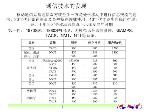
移动通信系指通信双方或至少一方是处于移动中进行信息交流的通 信。20年代开始在军事及某些特殊领域使用,40年代才逐步向民用扩展;
最近十年间才是移动通信真正迅猛发展的时期. 第一代: 1970S末、1980S初出现,为模拟话音通信系统,如AMPS,
TACS,NMT,NTT等系统。
1
I
• 第二代:1980S末出现,传递话音和低速数据,为 窄带数字通信系统,如GSM,PDC,D-AMPS, CDMA(IS95) 等。
• 4)足够的系统容量,强大的多种用户管理能力, 高保密性能和服务质量。
4
I
3G对RTT要求
• RTT(Radio Transmission Technology)无线传输技术
• 高速传输以支持多媒体任务①室内环境至少 2Mbit/s;②室内外步行环境至少384kbit/s;③室 外车辆运动中至少144kbit/s;④卫星移动环境至 少9.6kbit/s。
3
I
3G的目标
• 1)能实现全球漫游:用户可以在整个系统甚至全 球范围内漫 游 ,且可以在不同的速率、不同的运 动状态下获得有质量保证的服务;
• 2)能提供多种业务:提供话音、可变速率的数据、 活动视频非话业务,特别是多媒体业务;
• 3)能适应多种环境:可以综合现有的公众电话交 换网(PSTN)、综 合业务数字网、无绳系统、 地面移动通信系统、卫星通信系统、提 供无缝隙 的覆盖;
• FDMA是以不同的频率信道实现通信的,TDMA是以不同的时隙实现 通信的,CDMA是以不同的代码序列实现通信的。
6
I
频分多址FDMA
• 频分,有时也称之为信道化,就是把整个可分配 的频谱划分成许多单个无线电信道(发射和接收 载频对),每个信道可以传输一路话音或控制信 息。在系统的控制下,任何一个用户都可以接入 这些信道中的任何一个。
通信原理课件2.6
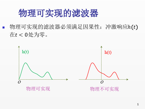
物理可实现的滤波器必须满足因果性:冲激响应ℎ
在 < 0处为零。
h(t)
O
h(t)
O
物理可实现
物理不实现
1
延迟后物理可实现的滤波器
本课中,滤波器的幅度增益和绝对延迟一般不影响
问题的实质。也即: ℎ 与 ∙ ℎ − 0 无实质差别。
在这个意义下,若某个设计中的ℎ 非因果,但其
低通滤波器是不可实现的:
滤波器误差最大的地方正好
是输入信号最大的地方,滤
波器误差对信号的影响大。
6
总之在本课中,滤波器不可实现的意思
是:以截短延迟的方式来近似实现时,近
似误差带来的影响可以忽略。
近似误差带来的影响与具体问题有关,因
此有可能出现这种情况:同样的滤波器在
A问题中认为可实现,在B问题中认为不
延迟ℎ − 0 因果,那么我们不会因为ℎ 非因果
而认为该设计不可行。也就是说,我们不把这个
ℎ 归到不可实现的类别中。
为了数学分析的简便,本课中经常谈论非因果的
ℎ ,但我们心里十分清楚的是:物理实现的时候,
一定是按照ℎ − 0 来制作的。
2
无限宽的冲激响应
如果冲激响应ℎ 展布在 −∞, ∞ 上,则任意有限的t0
可实现。
都不可能使ℎ − 0 成为因果滤波器。此时可将ℎ 截
短后近似实现:
ℎ − 0 ,
෨
ℎ =ቊ
0,
h t
0≤≤
else
h t
T
t0
O
t
O
t
3
近似误差的影响决定可实现性
通信原理演讲稿
通信原理演讲稿各位老师、亲爱的同学们,大家好!今天我非常荣幸能够在这里和大家分享关于通信原理的知识。
通信原理作为现代信息技术的基础,对我们的生活和工作都有着重要的影响。
通过这次演讲,我希望能够让大家对通信原理有一个更深入的了解,同时也能够认识到通信原理在我们日常生活中的重要性。
首先,让我们来了解一下通信原理的基本概念。
通信原理是指利用一定的传输媒介,将信息从发送方传输到接收方的过程。
在这个过程中,需要经过编码、传输、解码等一系列步骤。
通信原理的核心在于信息的传输和处理,它涉及到很多的技术和理论,如调制解调、信道编码、多路复用等。
这些技术和理论的应用,使得我们能够通过电话、互联网、无线电、卫星等多种方式进行信息的传输和交流。
其次,让我们来看一下通信原理在现代社会中的应用。
通信原理的应用已经渗透到我们生活的方方面面。
比如,我们每天使用的手机通讯、互联网、电视广播等,都离不开通信原理的支持。
在工业生产中,通信原理也发挥着重要的作用,如自动化生产线的控制、远程监控等。
在医疗领域,通信原理的应用使得远程医疗、医学影像传输等成为可能。
可以说,通信原理已经成为现代社会发展的基石,推动了信息社会的进步和发展。
最后,让我们来谈一谈通信原理的未来发展。
随着科技的不断进步,通信原理也在不断发展和演变。
未来,随着5G、物联网、人工智能等新技术的兴起,通信原理将会迎来新的发展机遇。
5G技术的商用,将会为通信原理带来更高的传输速率和更低的时延,为人们的生活带来更多的便利。
物联网的发展,将会使得各种设备能够实现互联互通,为人们的生活和工作带来更多的可能性。
人工智能的应用,将会使得通信系统能够更加智能化,为人们提供更加个性化的服务。
可以预见,通信原理在未来的发展中将会发挥更加重要的作用,为人类社会的发展做出更大的贡献。
总而言之,通信原理作为现代信息技术的基础,对我们的生活和工作都有着重要的影响。
通过今天的分享,我希望大家能够对通信原理有一个更深入的了解,认识到通信原理在我们日常生活中的重要性。
- 1、下载文档前请自行甄别文档内容的完整性,平台不提供额外的编辑、内容补充、找答案等附加服务。
- 2、"仅部分预览"的文档,不可在线预览部分如存在完整性等问题,可反馈申请退款(可完整预览的文档不适用该条件!)。
- 3、如文档侵犯您的权益,请联系客服反馈,我们会尽快为您处理(人工客服工作时间:9:00-18:30)。
Lecture 13Bandpass Modulation and DemodulationDr. Xin Zhang School of Electronics and Information EngineeringSouth China University of TechnologyReviews of Lecture 12Eye patternTransversal equalizerZero-forcingMSEModulation motivationDigital bandpass modulation Coherent modulationNoncoherent modulatione.g. A Zero-Forcing Three-Tap EqualizerConsider that the tap weights of an equalizing transversal filter are to be determined by transmitting a single impulse asa training signal. Let the equalizer circuit in Figure 3.26 bemade up of just three taps. Given a received distorted set of pulse samples {x(k)}, with voltage values 0.0, 0.2, 0.9, -0.3, 0.1, as shown in Figure 3.25, use a zero-forcing solution to find the weights {c-1, c0, c1} that reduce the ISI so that the equalized pulse samples {z(k)} have the values, {z(-1) = 0, z(0) = 1, z(1) = 0}. Using these weights, calculate the ISI values of theequalized pulse at the sample times k = ±2, ±3.What is the largest magnitude sample contributing to ISI, and what is the sum of all the ISI magnitudes?SolutionFor the channel impulse response specifiedz=x ce.g. A Zero-Forcing Three-Tap Equalizer (2)orSolving these three simultaneous equations results in the following weights:The values of the equalized pulse samples {z(k)} corresponding to sample times k =-3, -2, -1, 0, 1, 2, 3 are computed by using the preceding weights in Equation (3.89a),yielding0.0000 -0.0428 0.0000 1.0000 0.0000 0.1171 0.0345Introduction•4.2.1 Phasor Representation of a SinusoidPhasor representation of a sinusoid.•4.2.1 Phasor Representation of a Sinusoid (2)First, within this compact from, , is contained the two important quadrature components of any sinusoidal carrier wave, namely the inphase (real) and thequadrature (imaginary) components that are orthogonal to each other.Second, the unmodulated carrier wave is conveniently represented in a polar coordinate system as a unit vector or phasor rotating counterclockwise at the constant rate of radians/s.Third, when it comes time to modulate the carrier wave with information, we can view this modulation as amethodical perturbation of the rotating phasor.Figure 4.3 Amplitude modulation.•4.2.1 Phasor Representation of a Sinusoid (3)Figure Narrowband frequency modulation.•4.2.1 Phasor Representation of a Sinusoid (4)•4.2.2 Phase Shift KeyingThe general analytic expression for PSK is shown above.Phase shift keying (PSK) was developed during the early days of the deep-space program; PSK is now widely used in both military and commercial communicationssystems.•4.2.3 Frequency Shift KeyingAt the symbol transitions, the figure depicts a gentle shift from one frequency (tone) to another. This behavior is only true for a special class of FSK called continuous-phase FSK (CPFSK)•4.2.4 Amplitude Shift KeyingBinary ASK signaling (also called on–off keying) was one of the earliest forms of digital modulation used in radio telegraphy at the beginning of this century.•4.2.5 Amplutude Phase KeyingWhen the set of M symbols in the two-dimensional signal space are arranged in a rectangular constellation, thesignaling is referred to as quadrature amplitudemodulation(QAM).•4.2.6 Waveform Amplitude CoefficientThe waveform amplitude coefficient appearing in Equations (4.7) to (4.10) has the same general form for all modulation formats.Since the energy of a received signal is the key parameter in determining the error performance of the detectionprocess, it is often more convenient to use the amplitude notation in Equation above because it facilitates solving directly for the probability of error P E as a function of signal energy.4.3 DETECTION OF SIGNALS IN GAUSSIAN NOISE Equivalence theorem: Performing bandpass linear signal processing, followed by heterodyning the signal tobaseband yields the same results as heterodyning thebandpass signal to baseband, followed by baseband linear signal processing.The term “heterodyning” refers to a frequency conversion or mixing process that yields a spectral shift in the signal.As a result of this equivalence theorem, all linear signal-processing simulations can take place at baseband , withthe same results as at bandpass.•4.3.1 Decision RegionsM = 2AWGNd(r, s i) = ||r –s i|| The detector’s task after receiving r is to decide which of the signals (s1or s2,) was actually transmitted. The method is usually to decide on the signal classification that yields the minimum expected P E.•4.3.2 Correlation ReceiverThe received signal is the sum of the transmitted prototype signal plus the random noise:Detection process:1. the received waveform, r(t), is reduced to a singlerandom variable z(T), or to a set of random variables z i(T) (i= 1, . . . , M), formed at the output of the demodulator and sampler at time t = T, where T is the symbolduration.2.a symbol decision is made on the basis of comparingz(T) to a threshold or on the basis of choosing themaximum z i(T).•4.3.2 Correlation Receiver (2)Step 1 can be thought of as transforming the waveform into a point in the decision space. This point can bereferred to as the predetection point, the most criticalreference point in the receiver. Step 2 can be thought of as determining in which decision region the point islocated.For the detector to be optimized (in the sense of minimizing the error probability), it is necessary tooptimize the waveform-to-random-variabletransformation, by using matched filters or correlators in step 1, and by also optimizing the decision criterion instep 2.•4.3.2 Correlation Receiver (3)The verb “to correlate” means “to match.” The correlators attempt to match the incoming receivedsignal, r(t), with each of the candidate prototypewaveforms, s i(t), known a priori to the receiver. Areasonable decision rule is to choose the waveform, s i(t), that matches best or has the largest correlation with r(t).In other words, the decision rule isChoose the s i(t )whose index corresponds to the max z i(T)•4.3.2 Correlation Receiver (4)Figure Correlator receiver with reference signals {s(t)}.iFigure Correlator receiver with reference signals {}.•4.3.2 Correlation Receiver (5)•4.3.2 Correlation Receiver (6)In the case of binary detection, the correlation receiver can be configured as a single matched filter or product integrator with the reference signal being the difference between the binary prototype signals, s1(t)-s2(t). Theoutput of the correlator, z(T), is fed directly to thedecision stage.•4.3.2 Correlation Receiver (7)For binary detection, the correlation receiver can also be drawn as two matched filters or product integrators, one of which is matched to s2(t), and the other is matched to s2(t). In the decision stage ,the correlator outputs z i(T) (i = 1, 2) can be differenced to form Z(T) =z1(T) -z2(T).•Binary Decision ThresholdConditional probability density functions: p(z/s1), p(z/s2).The abscissa z (T ) represents the full range of possible sample output values from the correlation receiver shown in Figure above.With regard to optimizing the binary decision threshold for deciding in which region a received signal is located, we found in Section 3.2.1 that the minimum errorcriterionfor equally likely binary signals corrupted by Gaussian noise can be stated as•Binary Decision Threshold (2)4.4 COHERENT DETECTIONConsider the following binary PSK (BPSK) example:Let •4.4.1 Coherent Detection of PSKAssume that s1(t) was transmitted. Then the expectedvalues of the product integrators in Figure above, with reference signal ,are found as•4.4.1 Coherent Detection of PSK (2)where E{} denotes the ensemble average, referred to as the expected value .The decision stage must decide which signal wastransmitted by determining its location within the signalspace.•4.4.1 Coherent Detection of PSK (3)•4.4.2 Sampled Matched FilterThe impulse response of the matched filter is a delayed version of the mirror image (rotated on the t = 0 axis) of the input signal waveform. Therefore, if the signalwaveform is s(t), its mirror image is s(-t), and the mirror image delayed by T seconds is s(T -t).The impulseresponse h(t) of a filter matched to s(t) is then described by•4.4.2 Sampled Matched Filter (2)Figure above shows how an MF can be implemented using digital hardware.•4.4.2 Sampled Matched Filter (3)Sampledmatchedfilterdetectionexample,neglectingnoise.•4.4.2 Sampled Matched Filter (4)Note that a correlator only computes an output once per symbol time, such as the value of the peak signal at time T.If there are timing errors in the correlator, then the sampled output fed to the detector may be badlydegraded.。
