施乐1080说明书
W1070+_W1080ST+中文使用说明

中,内部的重要部件上可能会凝结湿气。 在温
安装。
度突然变化后,至少 2 小时内请勿使用投影
如果您不是使用 BenQ 的投影机吊装套件,可能会因使 机,以防止投影机受到损坏。
用规格或长度错误的螺丝造成安装不当,从而导致投影
机从天花板上掉下来。
避免使用挥发性液体
您可以向 BenQ 投影机经销商购买 BenQ 投影机吊装套 件。BenQ 建议您还要另外购买一条与 Kensington 锁配 套的安全绳,并将其牢牢连接到投影机上的 Kensington
4
重要安全说明
13. 投影机可以吊装,以便显示倒像。请使用 BenQ 的吊装套件来安装投影机。
15. 维修应由专业技术人员进行。
投影机吊装
湿气凝结
在从寒冷环境移动至高温环境后,请勿立即使
如果您要吊装安装投影机,我们强烈建议您使用合适的 用投影机。当投影机置于温度巨大变化的环境
BenQ 投影机吊装套件,以确保投影机安全、牢固地
3. 请勿垂直竖立投影机,否则会导致投影机倾倒,造 成伤害或导致投影机受到损坏。
- 火警附近的地方。 - 环境温度超过 35°C/95°F 的地方。
- 海拔高于 2000 米的地方。
2000 米
0米
重要安全说明
3
5. 当投影机打开时 (即使处于待机模式),请勿 9. 在使用过程中不要直视投影机镜头。强光束可
2
目录
校正梯形失真 ..............................................27
菜单功能 ..28
关于屏显菜单 ........................................ 28 使用基本屏显菜单 ............................... 30
AC1080专业运动动作相机用户手册说明书

AC1080 Professional Sports Action CameraUser ManualTABLE OF CONTENTS1) Precaution-----------------------------------------------------------------------12) Accessories---------------------------------------------------------------------23) Camera structure---------------------------------------------------------------34) Camera features----------------------------------------------------------------45) Two-way remote control------------------------------------------------------56) Overview------------------------------------------------------------------------67) Basic operation-----------------------------------------------------------------78) Photo and video-----------------------------------------------------------------89) Advanced menu settings-------------------------------------------------------910) Uploading files----------------------------------------------------------------1011) Firmware update--------------------------------------------------------------1112) Battery -------------------------------------------------------------------------1213) Syncing the remote control--------------------------------------------------1314) Camera and accessory assembly--------------------------------------------1415) Specifications sheet-----------------------------------------------------------1516) Troubleshooting---------------------------------------------------------------16PRECAUTIONFailure to follow these steps each time may result in damage to your camera, and could possibly destroy your camera. Your warranty does not cover accidental damage or issues caused by user error.*The camera is not drop resistant, therefore please avoid unnecessary roughness when handling the camera. Try to avoid dropping or damaging the camera in any way.*Don’t keep the camera in moist circumstances for long periods of time.*Don’t keep the camera in high temperatures as it may cause damage of external and internal components.*Use a specialized cloth to clean the camera lens and wipe away fingerprints or dust.*For the best and most efficient usage of your battery, we suggest using it in 0-40 °C.*When inserting or removing the micro SD card, please keep the camera turned off to avoid damage of the card or saved files.*Store the camera in a dry place and remove the micro SD card if storing for long periods of time.About the SD card:*Please use a Class 4 or higher speed micro SD card.*Please use genuine micro-SD cards. The non-genuine or OEM cards may cause issues, such as the failure of buttons, invalid video/photo issues, turning the camera off during recording, causing the camera to die, and so on.About the waterproof case:*Please keep the rubber seal clean, even a single hair or grain of sand can cause a leak. It is best to clean it with a dusting cloth.*For every use of the case in salt water, you will need to rinse the outside of the housing with fresh water and dry the case. Failure to do this will eventually cause corrosion of the hinge pin, and salt will build up in the seal, which can cause failure.*Please do not to remove or reset the seal. Doing so may cause leaks and damage your camera.About adhesive mounts:*Please mount on clean and smooth surfaces only. Only attach a mount in room temperature conditions 24 hours before use.ACCESSORIESX-gamecam+LCD waterproof case Remote controller USB cable1/4 tripod mountBattery Flat adhesive mount Vented adhesivemount Manual*Headbelt mount*Helmet mount*Bike mount*Surfboard mount*Chest harnessmount *Car suction cupmountNoted: *marked are optional accessories.1、Video button2、Photo button3、Micro SD card slot4、Microphone5、Lens6、Speaker7、A V OUT8、HDMI9、Right button10、U SB11、P ower/playback12、R ed/status indicator13、G reen/power indicator14、U p button15、L eft button16、O peration buttons17、D own button18、M enu/deleteCAMERA FEATURES* Mini size 2.6 x 1.8 x 1.3 inches, about 90g* FULL HD 1080P recording* Integrated 1.5 inch LCD screen* Waterproof case 60M (196 FT), shockproof 2M and dustproof* Waterproof remote controller, remote distance 15-20M* Fast forward, Slow-motion* Digital Image Stabilizer (DIS)* Contrast, ISO, Metering adjustment* One button back to pre-record mode* Pause and seamless recording* 180 degree upside down video/image* Sound-recognition* 4x digital zoom under 720p* View angle: 170 degree* Video: HD resolution1080p: 1920x1080, 30fps720p: 1280x720, 60fps;720p: 1280*720, 30fps*12M picture* Lithium battery: max 2.5 hours, 1000mAh* H.264 advanced compression, HDMI output*OSD Language: English, German, French, Italian, Russian, Spanish, Portuguese, Japanese, KoreanTWO-WAY REMOTE CONTROLThe remote control has a red indicator. It sends out signal but also gets signal feedback from the camera as well. When the remote controls sends out signal, it will flash once. When the camera receives signal (executive command) successfully, the red indicator will flash again. If the camera does not get signal, the remote control will only flash once. Using this information, you can check the camera status by following the indicator, usually when you cannot see the camera easily.OVERVIEWMain Buttons:Power/playback button Menu/delete button PHOTO button Video button Photo mode Video mode Advanced setting mode USB modeVideo resolution, Default 1080p Photo resolutiondefault 5MMicro SD card inside Metering statusDefault centralSelf-shot White balance Time stamp PowerTime on LCD (for example):02:46:48 ----- The remaining video record time2014-1-1 08:09:10 ----- Actual real-time clockBASIC OPERATIONSWhen using the camera for the first time:A. Insert a micro SD card. Without the micro SD card, the green indicator will flash.The camera is compatible with high speed micro SD cards (class 4 or higher)B. Insert the battery into the camera (Located on the bottom of the camera).C. Turn the camera on.Press and hold the POWER button for 3 seconds, you will see the startup screen, and the green LED indicator will turn on.Press and hold the POWER button for 3 seconds when your camera is on to turn it off.In standby mode, the red LED indicator is off.D. Recording video.When the camera is on, press the VIDEO button and your camera will begin to record video.The red LED indicator will flash. It also can be controlled by the VIDEO button on the remote controller.Note: During recording, you can only use the PHOTO button after pressing the VIDEO button on the remote controller.E. Taking photos.When your camera is on, press the PHOTO button and the camera will take a photo.The red LED indicator will flash once. You can also take a photo by pushing the PHOTO button on the remote controller.F. One button back mode.When you are setting options in the menu or reviewing files, just press the VIDEO button once, and your camera will go back to the pre-record mode.G. Playback mode and delete.By pressing the playback button, you can see all video files.Press the PHOTO button to switch between seeing videos and photos.The data in the top right corner shows the file number.Choose the video or photo you would like to view by using the 4 directional buttons.When viewing videos or photos, press the M button to delete the file.H. Pausing and seamless recording.During recording, pressing the UP button will allow you to see the recording time. The LCD will actually pause, but the red indicator will stay on.When you press the UP button again, the camera will start recording again. Doing this in succession allows you to record seamless footage as one file.PHOTO AND VIDEOPhoto*Press the MENU (M) button; you will see the photo icon.*Press the OK button to go into the photo’s setting menu.*Press M or VIDEO button to go back.Photo settings Size:3M5M8M12M Self shotOff5 sec10sec20sec Triple shot ON/OffTime lapse OFF/2/3/5/20/30/60 secIf choosing a Timelapse interval, when you press the PHOTO button once, it will take photos continuously.The red indicator will flash once each time a photo is taken.Press the PHOTO button again to stop.Video*Press the MENU (M) button; you will see the video icon.*Press the OK button to go into the video settings menu.*Press the M or VIDEO button to go back.Video setting Resolution1080P/30fps720P/60fps720P/30fpsWVGA/60fpsWVGA/30fpsVGA/30fps Motion detection OFF/on Video durationAny duration30sec180sec300secLoop recording Off/ON Upside down Off/ONNote: Enabling “upside down” will cause the LCD to go black for a few seconds, which is normal.*Sound recognition:When the camera begins to record, you will only hear one *beep* noise.When the camera stops recording, you will hear two *beep* noises.This helps recognize the recording status easily.*4x digital zoom:During 720p recording, you can zoom the video by using the LEFT and RIGHT buttons.*Fast forward, Slow-motion:When playing back video, press the LEFT button to choose slow motion.Press the RIGHT button to fast forward.PlaybackPressing the PLAYBACK button allows you to view your files. Press the directional buttons to choose your video. Press the OK button for a preview and press the MENU/DELETE buttons for your deletion options. When playing video, press the LEFT/RIGHT buttons to fast-forward and rewind.Press the PHOTO button to switch between photos and videos.ADVANCED MENU SETTINGSMenu settings:Using the SETUP feature, you can customize the camera's functions based on your personal preferences.*Press the MENU button; navigate to the Settings icon (third from the left).*Press the OK button to go into the settings menu.*Press the M or VIDEO button to go back.Advanced setting Firmware versionTime setup year/month/day, timeLCD offoff5sec10sec2minV olume 11 10 9 8 7 6 5 4 3 2 1 0Default Yes/NoFormat No/YesLanguageEnglish, German, French, Italian,Russian, Spanish, Portuguese,Japanese, KoreanTV standard NTSC /PAL TVDate/time stamp On/ OffBeep sound on/ offScene modeAuto, Night, Sports, LandscapePortraitFrequency 50HZ/60HZ Contrast Standard Hard softAE ISO Auto 100200 400 800Metering mode Standard Hard SoftAuto power offoff 1min 2min 5minUPLOADING FILESWhen connecting the USB with the camera successfully, there will be a visible ‘connection’ iconon the screen.Note: Before inserting the USB cable, please turn on the camera. When the camera is off, the cable is for charging only.FIRMWARE UPDATE*Usually the software can be updated by using a micro SD card.*Copy the software into card’s root folder, then insert the card into the camera and turn it on.*Choose YES, and the camera will refresh automatically. Restart the camera, and it will update successfully. BATTERYThe lithium-ion battery included in the packaging comes only partially charged. For a full charge, whenthe camera is off, connect the camera to a computer using the USB cable for charging.*Active battery time runs about 2.5 hours.*The battery will charge up to 80% in 1-2 hours, and should reach 100% in 4 hours.*When the camera is off, the red indicator is turned on during charging. After becoming fully charged, the green indicator will be on.* You can also charge the camera using a car charger or USB power bank.SYNC THE REMOTE CONTROL:* Open the remote controller (RC) and take off the battery.* Press and hold the PHOTO button of the remote controller, then install the RC's battery. Next, turn on the camera (when turning on the camera, you will still need to press the PHOTO button).* After turning on the camera, release the PHOTO button.CAMERA AND ACCESSORY ASSEMBLYTo assemble the waterproof case, please follow the below steps outlined in the image.Note that the buckle will not move after fixing the thumb screw.To attach your camera to the mount, you only need to slide it in to install and slide it out to uninstall.Tips:*Clean the surface first. Wax, oil, dirt, and other debris will reduce adhesion which can result in a weak bond or even losing your camera.*Please also keep your waterproof case's rubber door clean.*Only attach a mount in room temperature conditions. It will not bond well in very cold or damp environments.*The adhesive mounts can only be mounted to a smooth surface.*For best results, please attach your mount at a minimum of 24 hours before usage. SPECIFICATIONS SHEETVideo resolution 1080P(1920*1080)720P(1280*720)WVGA(848*480)QVGA(320*240)frames 1080P/30fps,720P/60fps,720P/30fps,WVGA/60fps, WVGA/30fps, QVGA/60fpsVideo format MOV(H.264 advanced compression)LCD size 1.5''Remote distance 15-20MWaterproof IP68,60M (196 FT)Storage Micro SD/MMC(Max 32GB SDHC)Storage capacity (32GBmicro SDcard) Photos: 3M(26080) 5M(15280) 8M(11180) 12M(8940)Video: H.264 1080p: about 5.5 hours;H.264 720p: about 5.5hoursZoom 4xdigital zoom(720P mode)A V OUT Support NTSC/PAL, HDMI outputPC port USB2.0(U-disk)Microphone Built-in MIC and SpeakerConsumption **********(MAX)Battery capacity 1000mAhBattery life About 2.5 hoursBattery charge About 2.5 hoursOperation system(1080P) Windows XP SP2/Vista or Above/Mac OS/Win 7/APPCPU >=Pentium 4 1.5GHZRAM >=1GBDimensions 68*46*33mmCamera weight 90g(with LCD)Storage temperature -20°C–50°CWorking temperature -10°C—50°CWorking humidity 15~85%RHTROUBLESHOOTING:Please refer to the below solutions if there are problems under normal operation.* Can’t record photos or videos.Check the memory left on your Micro SD card.* “File error” shows up when playing back photos and videos.Caused by corrupted storage, we recommend formatting your Micro SD card. Formatting the card will delete the data in micro SD card permanently, including protected files. Therefore, please copy important data before formatting.* Dim Videos.Try using a specialized cloth to remove away blots, fingerprints, and dust before recording.* The micro SD card is not compatible with the camera.Try formatting your micro SD Card using a computer. Formatting the card will delete the data in micro SD card permanently, including protected files. Therefore, please copy important data before formatting.*Cannot upload data to the PC when using a USB cable.Please check to see if the camera is turned on. When the camera is off, it is only charging, and will not transfer files or recordings.For any other questions or inquiries, please don’t hesitate to contact us directly:Foscam Digital Technologies LLCE-mail: *****************Phone: Toll Free – 1-800-930-0949。
1080p高清数码摄像机用户手册说明书

User manualThe smallest high definition camera in the worldPrefaceThank you for purchasing our product, high definition digital camcorder, exquisite special sport design with multi-function.This user manual will give you full instruction of using the product, and also provide you information of the product in detail. Please read this manual carefully before using the product. Please keep this manual well. We hope our product could satisfy your need and wish to serve you for long-term.No further notice will be informed if technical specification or appearance of this product changed. SummaryThis high-tech mini HD camcorder is designed for the demand of the market. This product has the most electronic functions such as HD digital video, digital photo, USB data transfer, HDMI output…Large range of application, memorize every wonderful moment......Features●High Definition videos or photos●Lens: 5.0 mega pixel, CMOS●Video format: 1280×720, 30Fps, MOV●Photo format: 3200×2400 jpeg, 8.0 mega pixel.●Interface: USD2.0 / HDMI●HDMI Port: Support to display on high definition TV directly●High capacity Lithium-ion rechargeable battery●Support micro SD cardConfigurationA MODEB RESETC FAST FORWARDD FAST BACKWARDE RECORDF POWEROPERATING INSTRUCTION◆Charging the Battery1. Using the charger: One end of the USB cable connects the charger and another links to the USB port ofthe camcorder, camcorder light will flash when charging. After full charge, red light keeps on.2. Connect computer: Connecting the USB cable to computer could charge too, red indicator light flashwhen charging.◆Inserting &Taking out Storage Card( Micro SD card)1. Carefully insert the storage card into the card slot.2. To remove the card, push the card in lightly, and then release it, when the card is rebounded then pull itout.Note:1. Before using micro SD card. Please check whether it is locked;2. Please make sure micro SD card is oriented in the right direction. Inserting micro SDcard in the wrong direction might cause damage to the product and the micro SD card;3. If the card is not compatible with the product, it might not be read. In this case, take outthe card and insert it again, or change another micro SD card.◆Power onPress the POWER button slightly, red light on and off quickly then turn to blue, this device is powered on.◆Video mode1. This product automatically goes to video mode after it is powered on. The blue indicator light begins to light always.2. Press RECORD button to start taking video, the blue and red indicator light begin to bright always. Press RECORD button again to stop recording, the blue indicator light always on and red light off.◆Photo mode1. After power on this device, press the MODE button. The blue indicator light begins to flash always.2. Press RECORD button to take photo, the red light bright always and the blue light flash twice, And then enter to the standby mode again, the red light off and blue indicator light flash always.◆HDMI mode1. Connect the product to the TV or PC using HDMI line. Turn on the product to go to Video mode, then can see the frames which the same with the product’s lens. Press the Record button, It begin to take video. And can see the frames in the TV or PC immediately. Press the Record button can play the current video.2. Press the Mode button, enter into photo mode. Press the mode button again to enter into review mode. Press direction key forwards and backwards to review pictures and video taken.◆Review mode1. Turn on the product to go to Video mode. Press mode key to enter into Photo mode. And then press mode key to enter into Review mode. Press direction key forwards and backwards to review pictures or videos taken.2. User can press direction key to review taken pictures or videos. Press Record key to play the video in the TV. Press mode to exit.3. Delete While reviewing (reviewing pictures/video), press Mode key for 3 seconds, it will enter into setting mode. Press mode key to go to deleting display. Press the direction key to choose deleting option, press mode key to confirm.◆Setting mode1. Regardless of video/camera/review mode, press Mode key for 3 seconds to enter into setting mode. Pressing Mode key could enter each setting Menu (For detailed setting information, please refer to setting table).2. At any menu mode, pressing direction key will enable user to go to menu setting options to choose desired setting, then press Mode to confirm.3. At any mode or menu setting, press the record key can exit current setting to original mode.File storing◆USB Storage ModeIf had inserted micro SD card into product, after connect with computer, you can find two removable disks from “My computer” (one is internal storage, the other is external storage card); find the stored videos and pictures under “Removable hard disk/ DCIM/100MEDIA”, data can be saved, transferred, cut, copied and deleted through computer system.Tips:If the displayed picture is tagged with" ", then it is a video. Press Record key to play the video. Pressing Record key again it will come to pause. While playing video, you can use direction key to forward or backward playing. To exit playing mode, you have to press Record key to pause first, and then press direction key to go to the next file.◆Connecting product to TV or PC1. Connecting product to TV with an HDMI cable to review pictures and videos.2. Connecting product to PC with an HDMI cable to review pictures and videos. Functions of keysVideo ModePower Button Turn on or off the productRecord Button Take Video or Pause take videoMode Button Enter into photo modePhoto ModeRecord Button Take Video or Pause take videoMode Button Enter into review modeHDMI ModePower Button Turn on or off the productRecord Button Take Video or Pause take video or play video Mode Button Enter into photo mode/enter into review mode Forwards Next video or pictureBackwards Last video or pictureMode & Menu settingMode Menu SettingTaking Videos Size1280*720/848*480/640*480/320*240EV+0/-0.3/-0.7/-1/-1.3/-1.7/-2/+2.0/+1.7/+1.3/+1/+0.7/0.3 White B Auto/Sunny/Cloudy/Tungsten/FluorescentContrast Standard/Hard/SoftSharpness Standard/Hard/SoftEffect Vivid/monochrome/negative/sepia/art/offDuration No/15min/30min/45minRecycle No/1min/5min/10min/15min/20minPictures Size8M/5MEV+0/-0.3/-0.7/-1/-1.3/-1.7/-2/+2.0/+1.7/+1.3/+1/+0.7/0.3 Quality Fine/good/normalWhite B Auto/Sunny/Cloudy/Tungsten/FluorescentContrast Standard/Hard/SoftSharpness Standard/Hard/SoftEffect Off/Art/Sepia/Negative/ Monochrome/Vivid Selftimer No/YesBurst No/3pics/5picsTips:1.No drive is needed to be installed. U disc can only be used when the video camerais on.2. The TV and PC must have the HDMI port then the product can connect to it.Review Delete No/YesSlide Show No/1Second/3Second/5SecondSystem Volume0/1/2/3 (8)Language English/Japanese/Simplified Chinese/Chinese Traditional Date000 00 00Clock00:00Format Cancel/YesSys.reset No/YesAuto off Off/1minute/3minute/5minuteLight Freq50HZ/60HZVersion V.0000 00 0000SpecificationsSensor5M pixel CMOS sensorVideo Video format: 1280 * 720 30fps, MOV Photo Photo format: 3200 * 2400, jpeg Video output HDMI, support 720P output modeStorage Internal: 32MExternal: support 32GB (Max.)Interface: HDMI / USB2.0Battery500mAh lithium-ion rechargeable batteryWorking temperature-10℃ - 50℃Working humility 15% - 85%Product size: 108mm (L) * 28mm (W) * 18mm (H) (Approx.)Products weight36gTroubleshooting◆Cannot take pictures, videos and record voice?Please check if had inserted the micro SD already, and if this micro SD card have enough place.◆Images cannot be transferred to HDTV screen?Please make sure that HDMI cable is completely plugged into TV’S HDMI port. Please use the HDMI cable comes along with the HDDV.◆Pictures and videos taken are not clear?Please check whether lens is covered with any dirty. If so, clean the lens before using it.。
MAXREFDES1080高光度LED驱动器说明书
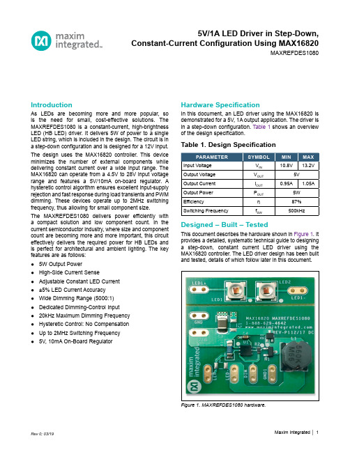
IntroductionAs LEDs are becoming more and more popular, so is the need for small, cost-effective solutions. The MAXREFDES1080 is a constant-current, high-brightness LED (HB LED) driver. It delivers 5W of power to a single LED string, which is included in the design. The circuit is in a step-down configuration and is designed for a 12V input. The design uses the MAX16820 controller. This device minimizes the number of external components while delivering constant current over a wide input range. The MAX16820 can operate from a 4.5V to 28V input voltage range and features a 5V/10mA on-board regulator. A hysteretic control algorithm ensures excellent input-supply rejection and fast response during load transients and PWM dimming. These devices operate up to 2MHz switching frequency, thus allowing for small component size.The MAXREFDES1080 delivers power efficiently with a compact solution and low component count. In the current semiconductor industry, where size and component count are becoming more and more important, this circuit effectively delivers the required power for HB LEDs and is perfect for architectural and ambient lighting. The key features are as follows:●5W Output Power●High-Side Current Sense●Adjustable Constant LED Current●±5% LED Current Accuracy●Wide Dimming Range (5000:1)●Dedicated Dimming-Control Input●20kHz Maximum Dimming Frequency●Hysteretic Control: No Compensation●Up to 2MHz Switching Frequency●5V, 10mA On-Board Regulator Hardware SpecificationIn this document, an LED driver using the MAX16820 is demonstrated for a 5V, 1A output application. The driver is in a step-down configuration. Table 1 shows an overview of the design specification.Table 1. Design SpecificationFigure 1. MAXREFDES1080 hardware.Designed – Built – TestedThis document describes the hardware shown in Figure 1. It provides a detailed, systematic technical guide to designing a step-down, constant current LED driver using the MAX16820 controller. The LED driver design has been built and tested, details of which follow later in this document.5V/1A LED Driver in Step-Down,Constant-Current Configuration Using MAX16820MAXREFDES1080Step-Down TopologyThe step-down converter, as seen in Figure 2, is the most commonly used type of switching regulator topology. A step-down converter steps down the voltage from input to output. Most conventional step-down converters consist of two switches (or a switch and a diode), an inductor, a capacitor, and a load (LEDs, in this case). The converter usually also requires a controller to regulate the output. This design uses the MAX16820.Transistor Switch ‘On’ PeriodWhen the transistor switch is on (t ON ), it supplies the output load with current. Initially current flow to the load is restricted, as energy is also being stored in the induc-tor. The current in the load and the charge on the output capacitor, therefore, build up relatively slow in comparison with the switch-on time of the MOSFET. During the ‘on’ period, there is a large voltage across the diode, which causes it to be reverse biased.Transistor Switch ‘Off’ PeriodWhen the transistor switch is off (t OFF ), the energy that had been stored in the inductor’s magnetic field is released. The voltage across the inductor is now in reverse polarity, and sufficient stored energy is available to maintain current flow while the transistor is open. The reverse polarity of the inductor allows current to flow in the circuit through the load and the diode, which is now forward biased. Oncethe inductor has been drained of the majority of its stored energy, the load voltage begins to fall. The charge stored in the output capacitor then becomes the main source of current. This leads to the ripple waveform seen in Figure 3.In this reference design, the circuit is modified to a reverse buck converter topology, as seen in Figure 4. This allows the circuit to operate off of a low-cost, n-channel MOSFET, which reduces BOM cost. The same basic theory is maintained in this topology, except the MOSFET and inductor come after the load.When the MOSFET Q1 is turned ON, current flows through the LEDs and inductor L1, and out through the MOSFET. Energy is stored in the magnetic field generated in the inductor. The current flowing through R SENSE is monitored by the MAX16820 at the CSN pin.Figure 2. Conventional step-down converter topology.Figure 3. Step-down converter waveforms.Figure 4. Reverse buck converter topology.When the MOSFET Q1 is turned OFF, the magnetic field in the inductor begins to collapse and the polarity of the inductor reverses. At the same time the inductor releases its remaining energy to the LEDs and the diode. This maintains constant current in the LEDs.In order to derive the duty cycle equation, first we look at t on , using:L di V Ldt=If integrated between 0 and t on :Lon L onI V Lt ∆=When the switch is on:V L = V IN – V OUTFill into the equation above:IN OUT ONLon(V V )t I L−=∆Now we look at t off , using:L diV Ldt=If integrated between 0 and t off :Lon L offI V Lt ∆=When the switch is off:V L = –V OUTFill into the equation above:OUT OFFLoff(V )t I L−=∆Because the average voltage across the inductor for an entire switching cycle is zero:ΔI Lon = –ΔI LoffFill in the equations above:IN OUT ON OUT OFFIN OUT OUT IN OUT OUT OUT OUT IN(V V )t (V )t L L (V V )DT (V )(1D)TV D V D V V DV D V −−=−−=−−−−=−=Design ProcedureNow that the principle operation of the buck regulator is understood, a practical design example can be illustrat-ed. The converter design process can be divided into three stages: power stage design, MAX16820 controller setup, and current regulation. This document is primarily concerned with the power stage design and the current setting. The design parameters in Table 2 will be used throughout.Step 1: Choosing Inductor L1In the MAXREFDES1080, the minimum inductor value for the circuit is the larger value of:IN LED LED LED LED3.33(V V )L 1.05I or 3.33(V )L 1.05I ×−=××=×L is calculated in μH.The inductor chosen for this design is 56μH.Step 2: Choosing R SENSE to Set theLED CurrentThe MAX16820 features a programmable LED current using a resistor connected between IN and CSN. Use the following equation to calculate the sense resistor:SNSHI SNSLO SENSE LED(V V )1R ()2I +Ω=Typically, V SNSHI = 210mV and V SNSLO = 190mV. For furtherdetails about V SNSHI and V SNSLO , see the Electrical Characteristics in the MAX16820 data sheet .The resistor chosen for this design is a 1%, 0.2Ω resistor.Table 2. Design ParametersStep 3: Determining the Switching FrequencyThe MAX16820 regulates the LED output current using an input comparator with hysteresis. As the current through the inductor ramps up and the voltage across the sense resistor reaches the upper threshold, the voltage at DRV goes low, turning off the external MOSFET. The MOSFET turns on again when the inductor current ramps down through the freewheeling diode until the voltage across the sense resistor equals the lower threshold. Use the following equation to determine the operating frequency:IN LED LED SENSE sw IN SNSHI SNSLO (V V )V R f V (V V )L−××=×−×Where V LED is the forward voltage drop across all LEDs in a string together, and f sw is the switching frequency.Step 4: MOSFET SelectionThe MAX16820’s gate driver is capable of sourcing 0.5A and sinking 1A of current. MOSFET selection is based on the maximum input operating voltage V IN , output current I LED , and operating switching frequency. For better effi-ciency, choose a MOSFET that has a higher breakdown voltage than the maximum input voltage, low R DS(ON), and low total charge. The MOSFET threshold voltage must be adequate if operated at the low end of the input-voltage operating range.The MOSFET chosen for this design is the Fairchild Semiconductor FDN359BN n-channel MOSFET.Design ResourcesDownload the complete set of Design Resources including the schematics, bill of materials, PCB layout, and test files.Step 5: Freewheeling Diode SelectionThe forward voltage of the freewheeling diode should be as low as possible for better efficiency. A Schottky diode is a good choice as long as the breakdown voltage is high enough to withstand the maximum operating voltage. The forward current rating of the diode must be at least equal to the maximum LED current.The diode chosen for this design is the Fairchild Semiconductor FBR130 Schottky diode.Step 6: LED Current RippleThe LED current ripple is equal to the inductor current rip-ple. In cases when a lower LED current ripple is needed, a capacitor can be placed across the LED terminals.Step 7: DIM InputThe MAX16820 allows dimming with a PWM signal at the DIM input. A logic level below 0.6V at DIM forces the MAX16820’s DRV output low, turning off the LED current. To turn the LED current on, the logic level at DIM must be at least 2.8V.NoteThe MAXREFDES1080 board is not thermally optimized for the LED components used.Revision HistoryMaxim Integrated cannot assume responsibility for use of any circuitry other than circuitry entirely embodied in a Maxim Integrated product. No circuit patent licenses are implied. Maxim Integrated reserves the right to change the circuitry and specifications without notice at any time. The parametric values (min and max limits) shown in the Electrical Characteristics table are guaranteed. Other parametric values quoted in this data sheet are provided for guidance.© 2019 Maxim Integrated Products, Inc. All rights reserved. Maxim Integrated and the Maxim Integrated logo are trademarks of Maxim Integrated Products, Inc., in the United States and other jurisdictions throughout the world. All other marks are the property of their respective owners.Maxim Integrated。
1080P行车记录仪说明书
行车记录仪说明书目录产品概述 (1)产品特性 (2)产品结构 (3)按键功能 (3)操作指南………………………………………4-5产品参数 (6)产品概述本产品是采用最新科技设计而成的数位高清摄影机,既可以作为一款普通的高清摄影机来使用,同时也是一款专业的高清行车记录器;录制解析度高达1920*1080P FULL HD 的高清解析影像,并使用最新的宽动态技术,同时也可拍摄800万的照片;使用TF卡作为存储设备,体积小巧。
和传统的摄影机相比较,本产品录制的FULL 高清影像,可以记录更加细致完美的视频画面,视频影像可通过电脑或高清电视机做高解析的播放。
使用本产品,享受真正HD 高画质生活。
产品特性◎镜头:6层全玻璃140度高清晰广角镜头◎重力感应器:G-sensor,重要影像保护。
(当记录仪受震动时,屏幕出现(锁)表示录制文件锁定、不被循环覆盖)◎移动侦测:当画面中没有动态时录制影像将停止写入TF卡内,使TF卡寿命更长◎录像:发动汽车自动开机,自动录影功能,每段视频为2/3/5分钟选择,卡满时自动覆盖最后一段视频◎存储卡:支持TF存储卡(1G-32G),建议使用6速以上高速卡◎视频:1920*1080P FULL HD 高画质解析度(使用电脑暴风影音/高清电视机观看视频,在导航屏幕显示画面是传输模拟信号、不清晰属正常迹像)◎录像分辨率:采用先进的H.264 影像压缩技术,有1920X1080、1280X720、VGA格式选择◎拍照模式:高达800万像素◎调节镜头:四倍变焦,范围12公分到无限远◎录像保护:无间隙连续录制功能,不会遗漏任何数据,强大的文档保护功能,在录制过程中,发生突然断电、机器损坏等情况,视频文档照样会完整保存◎录像回放:行车录影中可同步监看影像,支持现场重播◎可设定录影时间,时间到自动停止录影◎人性化的操作界面,使用简单方便安装方式1.先将TF卡插入机器。
2.将记录仪紧按在挡风玻璃上,确认主机已经牢牢贴在玻璃上。
施乐1080说明书
富士施乐复印机多功能一体机使用手册说明书
使用手冊- 適用於單機操作 -目錄重要的安全說明 (5)保護您的個人資料 (7)控制面板的說明 (8)使用液晶面板 (10)調整控制面板角度 (12)省電功能 (12)當關閉電源時 (13)電源故障後自動重新開機 (14)處理紙張和原稿選擇紙張 (16)放入紙張 (17)記憶卡的使用方法 (19)插入記憶卡 (19)移除記憶卡 (19)放置原稿 (21)自動進紙器 (ADF) (21)工作平台 (23)複印模式複印文件 (26)複製 / 修復相片 (28)複印模式選單清單 (31)相片模式列印相片 (34)使用各種版面配置列印 (36)列印格線紙 (38)列印相片賀卡 (40)從外部 USB 裝置進行列印 (43)備份資料至外部儲存裝置 (44)相片模式選單清單 (45)傳真模式連接電話線 (48)使用傳真專用的電話線路 (48)與電話裝置共用電話線路 (48)檢查傳真連線 (50)設定傳真功能 (51)設定快速撥號項目 (51)設定群組撥號項目 (52)建立標題資訊 (54)傳送傳真 (56)輸入或重撥傳真號碼 (56)使用快速撥號 / 群組撥號 (57)依次撥號發送 (58)在指定時間發送傳真 (60)透過連接的電話機發送傳真 (62)接收傳真 (63)自動接收傳真 (63)手動接收傳真 (65)輪詢接收傳真 (66)列印報告 (67)透過電腦發送傳真 (68)傳真模式選單清單 (69)掃描模式掃描至記憶卡 (72)掃描至電腦 (74)掃描模式選單清單 (75)設定模式 (維護)檢查墨水卡匣存量 (78)檢查和清潔印字頭 (79)校正印字頭 (81)設定 / 更改時間和區域 (83)透過數位相機列印 (85)設定選單清單 (87)解決方法錯誤訊息 (90)更換墨水卡匣 (91)清除夾紙 (94)夾紙 - 印表機內部 (1) (94)夾紙 - 印表機內部 (2) (98)夾紙 - 自動進紙器 (ADF) (99)夾紙 - 印表機內部 (3) (100)無法拉出紙匣 (103)列印品質 / 版面的問題 (105)傳真問題 (106)附錄 (107)2關於這本使用手冊當閱讀操作說明時,請遵守這些指導方針:w c Q R&警告:請務必小心遵守,以免身體受傷。
施乐1080出现U4的解决方法
施乐1080出现U4的解决方法
1按住0键5秒后同时按复印键进入诊断模式。
2输入代码50,然后按复印键,输入代码20,按复印键确认。
3(此时显示3,将3改为0),按AC键退回
4输入代码28,然后按复印键,输入代码47,按复印键确认。
5(看是否为3,否则改为3),按AC键退回
6输入代码28,然后按复印键,输入代码48,按复印键确认。
7(看是否为5,否则改为5),按AC键退回
8输入代码28,然后按复印键,输入代码49,按复印键确认。
9(看是否为175-198之间如果不是改到175-198之间),按AC键退回10输入代码38,然后按复印键,输入代码53,按复印键确认。
11(此时显示40改为47),不用按复印键确认。
12最后关机,开机OK
以上方法已多次输入为准,直到解决为止如果不行请直接按下面的方法操作试一下(1——3)(12)的步骤↓
进维修模式输50-20 如果是3把3改为0 ,按AC键退回
然后关机,再开机看一下
出现U4主要是由:电压不稳,定影组件积灰,操作不当,所造成的一般情况下建议买个2000VA的稳压器接上就OK了,只有这样U4才不会平凡出现、。
施乐DC 2000-1080数码复印机(培训手册)

50 分钟 整体学习
20 分钟 颁发结业报告
了解成像部分纸张输送和选购的单 学员练习 纸盘模块(STM)。
・ 了解打印、定影和副本排出顺序 ・ 在第 14 章,你将学习打印机和
扫描器规格。 ・ 再次阅读培训资料和手册,以作
更清晰的了解。 ・ 检查机器和周围的物品,并按顺
序装上它们。 教员签发结业报告
学员练习
・ 培训资料 ・ 手册
・ 培训资料 ・ 手册
・ 培训资料 ・ 手册
1-2
目录
第2章
复印过程
2-1
2.1 综述....................................................................................................................................... 2-1 2.2 系统概况 ............................................................................................................................... 2-1 2.3 复印过程 ............................................................................................................................... 2-2
这是一天的课程,下列时间安排可作参考。
自 9:00 9:10 09:30
所需时间 10 分钟 20 分钟 30 分钟
富士施乐多功能一体机复印指南说明书
Copy guide(複印指南)快速複印1將原始文件載入自動送件器中(面朝上,短邊先進入自動送件器)或放在掃描器玻璃上(面朝下)。
請注意:請不要將明信片、相片、小東西、專用透明投影膠片、相紙或細薄材質(如雜誌剪報)載入自動送件器。
將這些物品放置在掃描器玻璃上。
2若要將文件載入「自動送件器」,請調整紙張導引夾。
3從印表機控制面板上,按下4若您已將文件放在掃描器玻璃上,請觸控Finish the Job(結束工作)來返回主畫面。
利用自動送件器複印1載入原始文件,載入時面朝上,短邊先進入自動送件器。
請注意:請不要將明信片、相片、小東西、專用透明投影膠片、相紙或細薄材質(如雜誌剪報)載入自動送件器。
將這些物品放置在掃描器玻璃上。
2調整紙張導引夾。
3在主畫面上,觸控Copy(複印),或利用鍵台輸入複印份數。
這時會出現複印畫面。
4請依需求情況修改複印設定。
5觸控Copy It(複印它)。
使用掃描器玻璃複印1將原始文件面朝下放在掃描器玻璃的左上角。
2在主畫面上,觸控Copy(複印),或利用鍵台輸入複印份數。
這時會出現複印畫面。
3請依需求情況修改複印設定。
4觸控Copy It(複印它)。
5如果您要掃描多頁,接著請將下一份文件放在掃描器玻璃上,然後觸控Scan the Next Page(掃描下一頁)。
6觸控Finish the Job(結束工作)返回主畫面。
暫停列印工作以製作複印文件若要暫停目前的列印工作,以製作複印文件:請注意:Job Interrupt(工作中斷)必須設定為 On(開),此功能才可以運作。
1將原始文件載入「自動送件器」中(面朝上,短邊先進入「自動送件器」),或放在掃描器玻璃面板上(面朝下)。
請注意:請不要將明信片、相片、小東西、專用透明投影膠片、相紙或細薄材質(如雜誌剪報)載入「自動送件器」。
將這些物件放在掃描器玻璃面板上。
2若要將文件載入「自動送件器」,請調整紙張導引夾。
3從印表機控制面板,按下4如果您要掃描多頁,接著請將下一份文件放在掃描器玻璃上,然後觸控Scan the Next Page(掃描下一頁)。
施乐Office Finisher LX用户指南说明书

Version 1.0July 2008Office Finisher LX User GuideMicrosoft, MS-DOS, Windows, Windows NT, Microsoft Network, and Windows Server are either trademarks or registered trademarks of Microsoft Corporation in the United States and/or other countries.Novell, NetWare, IntranetWare and NDS are registered trademarks of Novell, Inc. in the United States and other countries.Adobe, Acrobat, PostScript, PostScript3, and PostScript Logo are trademarks of Adobe Systems Incorporated.Apple, AppleTalk, EtherTalk, LocalTalk, Macintosh, MacOS and TrueType are trademarks of Apple Computer, Inc., registered in the U.S. and other countries.HP, HPGL, HPGL/2, and HP-UX are registered trademarks of Hewlett-Packard Corporation.All product/brand names are trademarks or registered trademarks of the respective holders.The data saved in the hard disk of the machine may be lost if there is any problem in the hard disk. Xerox is not responsible for any direct and indirect damages arising from or caused by such data loss.Xerox is not responsible for any breakdown of machines due to infection of computer virus or computer hacking.Important(1) This manual is copyrighted with all rights reserved. Under the copyright laws, this manual may not be copied or modified in whole or part, without the written consent of the publisher.(2) Parts of this manual are subject to change without prior notice.(3) We welcome any comments on ambiguities, errors, omissions, or missing pages.(4) Never attempt any procedure on the machine that is not specifi cally described in this manual. Unauthorised operation can cause faults or accidents.Xerox is not liable for any problems resulting from unauthorised operation of the equipment.An export of this product is strictly controlled in accordance with Laws concerning Foreign Exchange and Foreign Trade of Japan and/or the export control regulations of the United States.Xerox and Ethernet are registered trademarks.Table of ContentsProduct Overview1-2 The Copy Output Screen1-4 Installing the Tray Attachment1-5 Loading Staples in the Automatic Stapler1-6 Loading Booklet Maker Staples1-8 Clearing Staple Jams1-10 Clearing Paper Jams1-14 Emptying the Hole Punch Waste Container1-17Product OverviewProduct OverviewThe Office Finisher LX is an optional device thatcan be used to staple your printed or copiedoutput.The optional Booklet Maker can be used to holepunch and crease your output.Descriptions for each of the Office Finisher LXcomponents and options are shown on thefollowing page.Product Overview Front Cover Open this cover when clearing paper jams orloading staples.Staple Cartridge Contains Staples used in the Automatic Stapler.Creasing Unit Makes a crease in each sheet of copies or prints foreasy manual folding.Finisher Tray Delivers outputs processed by the Office FinisherLX.Top Cover Open this cover when clearing paper jams.Booklet Staple Cartridges The Booklet Maker contains two booklet staplecartridges.Booklet Maker Side Cover Open this cover when replacing the booklet staplecartridges.Booklet Maker Makes stapled copies or prints with a crease foreasy manual folding.Tray Attachment Use this attachment when unstapled A4 LEF, 8.5 x 11” LEF, or B5 LEF paper is output to the Office Finisher LX tray.Interface Cover Open this cover when emptying the Hole PunchWaste Container.Hole Punch Waste Container Collects punched waste.The Copy Output ScreenThe Copy Output ScreenThe Copy Output screen allows you to sort copyoutputs. If the optional Office Finisher LX has beeninstalled, the stapling, hole-punching, and/orcreasing feature will also be available.NOTE: The features displayed on the CopyOutput screen vary depending on whether afinisher is installed on your machine, whether theinstalled finisher is an Office Finisher LX, an OfficeFinisher, or an Integrated Office Finisher, and whatoptions are installed on the finisher.Installing the Tray Attachment Installing the Tray AttachmentWhen unstapled A4 LEF, 8.5 x 11” LEF, or B5LEF paper is output to the Finisher tray, it is recommended to use the Tray Attachment. Remove the Tray Attachment from under theOffice Finisher LX Tray.Attach the Tray Attachment to the tray, as shown.Loading Staples in the Automatic StaplerLoading Staples in theAutomatic StaplerThe optional Office Finisher LX contains anautomatic stapler. When the finisher runs out ofstaples, a message appears on the touch screen.When this message is displayed, load a newstaple case into the staple cartridge.Make sure that the machine is not operating, andopen the front cover of the finisher.Hold the staple cartridge by the lever R1 and pullit to the right.Hold the staple cartridge by the orange lever andremove it from the finisher.NOTE: The staple cartridge is firmly inserted. Aslight force is required to pull the cartridge out ofthe finisher.CAUTION: Do not discard the Staple Cartridge.Only the used Staple Case should be discarded.The Staple Cartridge can be refilled with a newStaple Case.Loading Staples in the Automatic Stapler Pinch both sides of the empty staple case withyour fingers, and remove the staple case from the cartridge.Insert the front side of the new staple case into the staple cartridge, and then push the rear side into the cartridge.Hold the staple cartridge by the orange lever, and insert it into the finisher until it clicks.Close the front cover of the finisher.NOTE: If the front cover is not completely closed,a message will appear and the machine will not operate.Loading Booklet Maker StaplesLoading Booklet MakerStaplesIf the optional Booklet Maker is installed, amessage appears on the touch screen when theunit runs out of staples. When the message isdisplayed, load a new staple cartridge into theBooklet Maker. The Booklet Maker contains twostaple cartridges.Make sure that the machine has stopped, andopen the side cover of the finisher.Move the Booklet Maker Staple Cartridges so thatboth Staple Cartridges are easily accessible.Hold the tabs on both sides of the booklet staplecartridge and pull the cartridge out of the BookletMaker.Hold the tabs on both sides of the new bookletstaple cartridge, and insert it into the originalposition until it clicks.NOTE: If you have trouble inserting the cartridge,make sure that the staples in the cartridge areproperly in place.Loading Booklet Maker Staples Repeat steps 2 and 3 to replace the other booklet staple cartridge.Close the side cover of the Booklet Maker.NOTE: If the side cover is not completely closed, a message will appear and the machine will not operate.Clearing Staple JamsClearing Staple JamsThe following describes how to clear staple jamswhen the optional Office Finisher LX is installed.Clearing Staple Jams in the Automatic StaplerMake sure that the machine has stopped, andthen open the front cover on the Office FinisherLX.Hold the staple cartridge by Lever R1, and slidethe cartridge to the right.Hold the staple cartridge by the orange lever, andlift up to remove the cartridge.Check the inside of the Office Finisher LX for anyremaining staples.Clearing Staple Jams Pull up the front lever on the staple cartridge.Remove the entire sheet of staples, including the jammed staple.NOTE: Remove the entire staple sheet. Do not remove the jammed staple only.Pull down the front lever on the staple cartridgeuntil it clicks into place.Hold the staple cartridge by the orange lever, and return the cartridge to its original position.Close the front cover of the Office Finisher LX.If the staples cannot be removed after carrying out the above procedures, contact the XeroxWelcome Center.Clearing Staple JamsClearing Staple Jams in the Booklet Maker StaplerMake sure that the machine has stopped, andopen the side cover of the finisher.Move the Booklet Maker Staple Cartridges so thatboth Staple Cartridges are easily accessible.Hold the tabs on both sides of the booklet staplecartridge and pull the cartridge out of the BookletMaker.Repeat the step above for the other BookletMaker Stapler Cartridge.Check the inside of the Office Finisher LX for anyremaining staples.Clearing Staple Jams Hold the tabs on both sides of the new booklet staple cartridge, and insert it into the original position until it clicks.Repeat the step above for the other BookletMaker Stapler Cartridge.NOTE: If you have trouble inserting the cartridge, make sure that the staples in the cartridge are properly in place.Close the side cover of the Booklet Maker.Clearing Paper JamsClearing Paper JamsFollow the steps below to clear paper jams in theoptional Office Finisher LX.Office Finisher LX Top Cover JamsOpen the Office Finisher LX Top Cover.Remove the jammed paper.Close the Office Finisher LX Top Cover.Clearing Paper JamsOffice Finisher LX Transport Cover F JamsOpen the Office Finisher LX Transport Cover F.Remove the jammed paper.Close the Office Finisher LX Transport Cover F.Clearing Paper JamsBooklet Maker Paper JamsMake sure that the machine has stopped, andopen the side cover of the finisher.Remove the jammed paper.Close the side cover of the Booklet Maker.Emptying the Hole Punch Waste Container Emptying the Hole Punch Waste ContainerNOTE: Leave the power on when emptying the Hole Punch Waste Container. If the power isturned off, the machine will not recognize that the waste container has been emptied.Make sure that the machine has stopped, andthen open the Interface Cover on the Office Finisher LX.Pull out the Hole Punch Waste Container.Dispose of the Hole Punch waste.Push in the Hole Punch Waste Container.Close the Interface Cover on the Office Finisher LX.NOTE: If the Interface Cover is not completely closed, a message will appear and the machinewill not operate.。
W1070+_W1080ST+中文使用说明

投影尺寸 ....................................................... 14 投影镜头垂直移动 (仅适用于 W1070+)..................................................... 15
W1070+/W1080ST+
数码投影机 家庭影院 用户手册
目录
重要安全说明.................................3
简介...................................................6
投影机特点 ............................................... 6 物品清单.................................................... 8
高压组件,接触人体时可能会造成电击死亡。
用户唯一可维修的部分是灯泡。 请参见 第 51 页。
3. 请勿垂直竖立投影机,否则会导致投影机倾倒,造 成伤害或导致投影机受到损坏。
- 火警附近的地方。 - 环境温度超过 35°C/95°F 的地方。
- 海拔高于 2000 米的地方。
2000 米
0米
重要安全说明
3
5. 当投影机打开时 (即使处于待机模式),请勿 9. 在使用过程中不要直视投影机镜头。强光束可
- 温度过高的地方,如窗户紧闭的汽 车内。
- 过度潮湿、有灰尘或烟雾的地方,会污 染光学原件,缩短投影机使用寿命并使 图像变暗。
富士施乐1080使用说明书
在运行Microsoft Windows 2000/XP的计算机上的打印驱动程序中创建自定义纸张尺寸1. 对于Windows 2000操作系统,单击[开始],将鼠标指向[设置],然后选择[打印机]。
对于Windows XP/Server 2003操作系统,单击[开始],然后单击[打印机和传真]。
将显示"打印机"或"打印机和传真"窗口。
2. 右键单击打印机图标,然后选择[属性]。
将显示"属性"窗口。
3. 单击[配置]标签。
4. 单击[自定义纸张尺寸]按钮。
将显示"自定义纸张尺寸"窗口。
5. 单击[自定义1]。
6. 将设定调整到所需的尺寸。
7. 在指定的字段中输入自定义尺寸纸张的名称,然后单击[确定]。
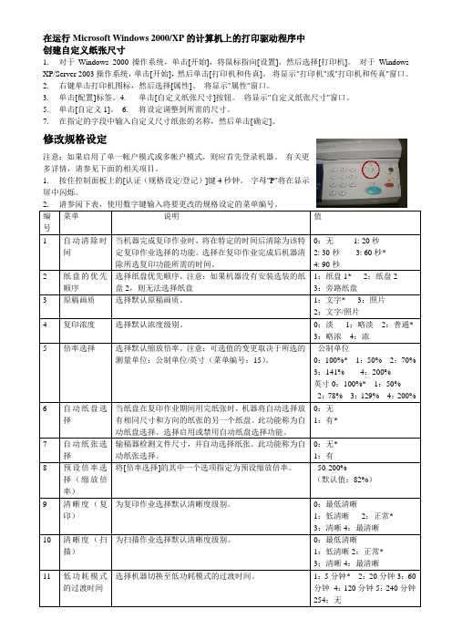
修改规格设定Array注意:如果启用了单一帐户模式或多帐户模式,则应首先登录机器。
有关更多详情,请参见下面的相关项目。
1. 按住控制面板上的[认证(规格设定/登记)]键4秒钟。
字母"P"将在显示屏中闪烁。
备注:1. *:默认设定 2 按[启动]键确认选择。
2. 请参阅上表,使用数字键为要更改的规格设定输入新值。
3. 按[启动]键确认选择。
字母"P"将在显示屏中闪烁。
4. 重复步骤2,以进行更多的规格设定更改。
5. 按控制面板上的[认证(规格设定/登记)]键,以退出规格设定模式。
设置纸盘中纸张的尺寸和方向1. 按住控制面板上的[纸张选择]键4秒钟,直到机器进入纸张设定模式。
2. 按[纸张选择]键,直到所需的纸盘在机器示意图上亮起。
3. 按[显示切换]键以在下列纸张类型中滚动: 当测量单位为公制时更改顺序当测量单位为英寸时更改顺序4. 注意:如果选择了纸盘1或纸盘2,A5和55将不会出现在显示屏上。
默认测量单位设为公制单位。
要进行更改,请更改规格设定菜单编号15。
有关更多详情,请参阅下面的相关项目。
Moticam 1080 数码显微镜相机说明书

110510. Optical instruments and MicroscopesMicroscopy/Digital microscopes and camerasGENERAL CATALOGUE EDITION 21E & OE.integrated software offers a new quality for interactive microscopy in educational,laboratory and industrial environments and allows working without additional computer. The HDMI signal delivers a fast live image with 1080 (60P) resolution and high color fidelity. Still images and videos are stored either at 2 MP or 8 MP format on MicroSD card. Especially for the visualisation of fast, moving samples in biology and industry 60 full frames per second are ideal system preconditions. The on-board software is controlled via WiFi mouse. As an alternative, the USB port of the camera can be used, also simultaneously to the HDMI port, to run the camera with the new Motic Images Plus 3.0 software with all its measuring tools. A HDMI video projector allows to present the impressive live image to a greater public. The delivery package includes the software Motic Images Plus 3.0, calibration slide, eyepiece adapters as well as macro tube with focusable lens.Moticam 1080 2.0/8 MP1/2.8''CMOS16.282 48812archiving and image processing.-C-Mount USB-camera with CMOS sensor-USB-cable, eyepiece adapter and calibration slide included-Kern-Microscope-VIS Software in 6 languages inclusive, for WINDOWS XP and higherODC 824 ODC 825 ODC 831 3,1 MP 5,1 MP 3,1 MP 1/2'' CMOS 1/2.5'' CMOS 1/3'' CMOS USB 2.0 USB 2.0 USB 3.0 1 1 1 6.285 783 6.285 906 6.285 907 3education. They are suitable for use in science teaching for detailed examination e.g. of insects, plants, minerals, fossils and mechanical and electrical components.-USB 2.0, 30 fps-VGA (640 x 480) or 1.3 MP image resolution -WF4115ZT with WLAN streamer-Incl. Dino-Lite software, for AM4113T and WF4115ZT the software also includes measurement functions -Warranty: 2 yearsScope of supply: Carrying pouch, Software CD for Windows and Mac OS, calibration sheet for AM4113T and WF4115ZT, manual46.285 94054.668 4576 4.675 29876.285 946。
Home Cinema 880和Home Cinema 1080项目器设置说明书
Quick SetupIMPORTANT: Before using this product, make sure you read these instructions and the safety instructions in the online User’s Guide.Note: These illustrations show the Home Cinema 1080, but the instructions are the same for the Home Cinema 880 unless otherwise noted. ContentsMake sure your projector box includes all of these parts:Connect the projectorVideo deviceHome Cinema 880Connect one end of an HDMI cable to the projector’s HDMI port and the otherend to an HDMI port on your video device.Home Cinema 1080Connect multiple video devices and use theSource Search button on theprojector or the remote control to switch between them.(composite video)ComputerConnect one end of an HDMI cable to the projector’s HDMI port and the otherend to an HDMI port on your computer.Note: For more information on connecting the projector to your computer orother devices (camera, USB flash drive, etc.), see the online User’s Guide.Connect audioBuilt-in speakerThe projector has a built-in speaker that can play audio from a video source(DVD player, streaming device, etc.) connected by an HDMI cable. If youconnected a composite video cable to the Home Cinema 1080, connect one endof an RCA audio cable to the projector’s audio input ports and the other end toyour video device’s audio output ports.RCA audio cableExternal speakersYou can connect the projector to external self-powered speakers through theAudio Out port.3.5 mm stereo mini to RCA cableNote: The projector’s internal speaker is disabled when you connect externalspeakers.Turn on your equipment1 T urn on your computer or video source.2 P lug in the projector. Thepower light on the projector turns blue.3 Open the A/V Mute slide all the way.4 P ress the power button on the projector or remote control. Theprojector beeps, the Status light flashes blue, and then stays on.Note: To shut down the projector, press the power button twice.5 U se the arrow buttons on the remote control to highlight any of theoptions on the Home screen that appears, then press to select it.You can switch between projection sources and quickly access variousadjustment options from this screen.6 T he default language of the menu system is English. To select anotherlanguage, press the Menu button on the projector or remote control.Select Extended and press . Select Language and press . Select yourlanguage and press . Press the Menu button to exit the menu system.Adjust the image1 I f you don’t see an image, press the Source Search button on theprojector or remote control to select the image source.Note: If you still see a blank screen or have other display problems, seethe troubleshooting tips on the back of this sheet.2 T3 HHring.4 To sharpen the image, turn the focus ring.5 I f your image looks like or , you may have placed the projectoroff to one side of the screen at an angle. Place the projector directly infront of the center of the screen, facing the screen squarely. If you can’tmove the projector, use the horizontal keystone slider on the projector tocorrect the image shape.6 Yor ,correct it.Using the remote controlInstall the batteries as shown (two AA batteries).Choose which sourceto displayTurn projectoron and offAccess projectormenusTurn off projectordisplay Access the HomescreenNavigate projectormenusFor more information on using the remote control, see the online User’s Guide.Mirroring a mobile deviceHome Cinema 1080: If your mobile device (laptop, smartphone, or tablet)supports Miracast®, you can project or mirror your device’s screen wirelessly. Youdo not need any additional software to use this feature.Note: Some restrictions apply. See the online User’s Guide for details.Select screen mirroring settings1 P ress the Menu button on the remote control.2 S elect the Network menu and press .3 S elect On as the Screen Mirroring setting.4 S elect Screen Mirroring Settings and press . Press again.5 S elect any of the Screen Mirroring Settings options as necessary. Seethe online User’s Guide for details.6 W hen you finish selecting settings, select Set and follow the on-screeninstructions to save your settings and exit the menus.Connect your device1 P ress the LAN button on the remote control. You see the Screen Mirroring standby screen.2Use the Miracast function on your device to search for the projector. You see a list of available devices.Note: See your device’s documentation for details on using its Miracast function.3If you see a PIN entry screen on your device, enter the PIN code displayed on the Screen Mirroring standby screen or at the bottom right of the projected image.The projector displays the image from your device once a connection is established.Caution: It may take some time to establish a connection. Do not disconnect the projector’s power cord while it is connecting to your device. Doing so may cause your device to freeze or malfunction.Troubleshooting• If you see a No signal message after turning on the projector, make sure your computer or video device is properly connected, and press the Source Search button.•I f you see a blank screen, check the following: •M ake sure the A/V Mute slide is open all the way. •M ake sure the Status light on the projector is blue and not flashing. •P ress the power button to wake the projector from standby or sleep mode, if necessary.• If you see a blank screen when a computer is connected, check the following:• On some Windows ® laptops, you may need to hold down the Fn key and press F7 or the function key that lets you display on an external monitor. It may be labeled CRT/LCD or have an icon such as .O n Windows 7 or later, hold down the Windows key and press P at the same time, then click Duplicate .• If you’re using a Mac laptop, open System Preferences and select Displays . Click the Arrangement tab and select the Mirror Displays checkbox.• If the projector does not respond to remote control commands, make sure the batteries in the remote control are installed correctly. Replace the batteries if necessary.RegistrationRegister today to get product updates and exclusive offers. You can register online at /webreg.EPSON is a registered trademark and EPSON Exceed Your Vision is a registered logomark of Seiko Epson Corporation.PrivateLine is a registered trademark of Epson America, Inc.Windows is a registered trademark of Microsoft Corporation in the United States and/or other countries. Mac is a trademark of Apple Inc., registered in the U.S. and other countries.General Notice: Other product names used herein are for identification purposes only and may be trademarks of their respective owners. Epson disclaims any and all rights in those marks.This information is subject to change without notice.© 2020 Epson America, Inc., 3/20Printed in XXXXXXCPD-58869Where to get helpManualsFor more information about using the projector, you can view or download the online manuals from the Epson website, as described below.Internet supportVisit /support (U.S.) or www.epson.ca/support (Canada) and search for your product to download software and utilities, view manuals, get FAQs and troubleshooting advice, or contact Epson.Telephone support servicesTo use the Epson ® PrivateLine ® Support service, call (800) 637-7661. This service is available for the duration of your warranty period. You may also speak with a support specialist by calling (562) 276-4394 (U.S.) or (905) 709-3839 (Canada). Support hours are 6 AM to 8 PM , Pacific Time, Monday through Friday, and 7 AM to 4 PM , Pacific Time, Saturday. Days and hours of support are subject to change without notice. Toll or long distance charges may apply.Optional accessoriesFor a list of optional accessories, see the online User’s Guide .You can purchase screens or other accessories from an Epson authorizedreseller. To find the nearest reseller, call 800-GO-EPSON (800-463-7766). Or you can purchase online at (U.S. sales) or www.epsonstore.ca (Canadian sales).。
EK-FC Titan X Pascal EK-FC1080 GTX Ti 背板 说明书

This product is intended for installation only by expert users. Please consult with a qualified technician for installation. Improper installation may result in damage to your equipment. EK Water Blocks assumes no liabilitySTEP 2: PREPARING YOUR GRAPHICS CARDEK-FC Titan X Pascal/1080 GTX Ti Backplate is very easy to install. First install EK-FC Titan X Pascal/1080 GTX Ti series water block according to its installation manual. If you have it already installed, please check the picture below to see which mounting screws are to be left in their position and which are to be removed. Please remove the six (6) M2.5x4 AX1 screws and their PVC washers as well (marked with arrow).EK-FC Titan X/1080 GTX Ti Backplate features passive cooling of the printed circuit board and its components therefore it is mandatory to install the enclosed thermal pad. Please install enclosed 1mm thick thermal pads (Thermal Pad F – 1,0mm (120x16) and Thermal PAD E - 1mm (RAM 8X)) as shown on the picture below. You may need to trim the excess thermal pad.Thermal PAD F - 1mm (120x16mm) EK-FC Titan X Pascal Backplate12 Thermal PAD E - 1mm (RAM 8X) 2 22 2 21STEP 4: ATTACHING EK-FC TITAN X PASCAL/1080 GTX Ti BACKPLATE TO THE GRAPHICS CARDTake enclosed mounting screws and install them as shown on picture below. Use six (6) M2.5x7 AX1 screws, and tighten them using Philips head screwdriver. HINT: Do not tighten screws until they are all positioned in their mounting holes. The backplate has milled in standoffs, so there is no fear of over tightening of the screws. Nevertheless do not exaggerate with screwing force as there is no need for it.By all means users must also consider that this product is intended to be used only with EK-FC Titan X Pascal/1080 GTX Ti series water blocks. No other 3rd party heat sinks or coolers are officially supported! EK does not offer any assistance or support in the latter application.M2.5x7 AX1IMPORTANT DISCLOSURESREQUIRED TOOLS AND MOUNTING SCREWS:Philips head screwdriver scissors。
施乐DC2000-1080数码复印机故障诊断

2.2.2 发生多项错误时的优先显示顺序 .................................................... 2-38
第 2 章 故障诊断
2.1 故障修复的概要
2.1 故障修复的概要
故障修复时,请依照下列流程进行作业。 执行事前确认后,确认现象,利用 FIP (Fault Isolation Procedure:故障分析步骤)与 [ “2.3 诊断模式”]、 [ 第 7 章 电气配线数据 ],有效执行作业。
设置状况的确认
figure21故障修复的前进方法设置状况的确认设置状况的确认故障状况的确认故障状况的确认执行fip执行fip故障修复的确认故障修复的确认结束结束诊断模式操作原理电气配线数据电气配线数据诊断模式操作原理参考信息参考信息第2章故障诊断21故障修复的概要22211设置状况的确认211设置状况的确认开始故障诊断之前请务必确认下列项目
z 依照 FIP 内的指示,连接 HVPS 上的连接器 (P / J520)时,切勿触摸 HVPS及高电压输出部分。 z 使用诊断模式输出高电压时,若无特别的指示,务必在盖子类全部安装好的状态下进行。而且,输出
高电压时,切勿触摸高电压输出部。 z 使用诊断模式的输入诊断、输出诊断执行驱动部的动作时,若无特别的指示,务必在盖子类全部安装
2.1.2 安全注意事项
z 执行作业时,若无特别必要,请务必拆下电源线。 打开电源时,切勿触摸通不必接触的通电部分。 即使电源拨关闭,LVPS 电源开关/插座部分依然处于通电状态, 切勿触摸通电部分。
Lorex 1080p HD Bullet Security Camera 用户指南说明书
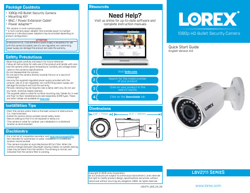
Connect the female power head to the included power adapter.
PCownneercAtdinagptehre TCyapmeseras
A multi-camera power adapter that provides power to multiple cameras or individual power adapters may be provided, depending on product configuration.
location is recommended.
Disclaimers
• For a full list of compatible recorders, visit /compatibility • Not intended for submersion in water. Installation in a sheltered
location recommended. • This camera includes an Auto Mechanical IR Cut Filter. When the
camera changes between Day/Night viewing modes, an audible clicking noise may be heard from the camera. This clicking is normal, and indicates that the camera filter is working.
C. LEVELING THE CAMERA: Rotate the camera until it is level with the viewing area, then tighten the adjustment screw.
- 1、下载文档前请自行甄别文档内容的完整性,平台不提供额外的编辑、内容补充、找答案等附加服务。
- 2、"仅部分预览"的文档,不可在线预览部分如存在完整性等问题,可反馈申请退款(可完整预览的文档不适用该条件!)。
- 3、如文档侵犯您的权益,请联系客服反馈,我们会尽快为您处理(人工客服工作时间:9:00-18:30)。
4 打印..................................................................... 61 设置打印机............................................................... 62 设置打印首选项 ........................................................ 62 指定自定义纸张尺寸 .................................................... 63 打印步骤................................................................. 64 取消打印作业 .......................................................... 65
2 产品概况 ................................................................. 17 机器部件 ................................................................. 18 正视图 ................................................................ 18 内视图 ................................................................ 20 后视图 ................................................................ 21 控制面板 ................................................................. 22 开机 / 关机 ............................................................... 24 开机 .................................................................. 24 关机 .................................................................. 24 节电中 / 解除 .......................................................... 25 管理帐户 ................................................................. 26 帐户模式 .............................................................. 26 以无帐户模式登录机器 .................................................. 26 以单一帐户模式登录机器 ................................................ 27 以多帐户模式登录机器 .................................................. 28 机器状态 ................................................................. 30
1 使用机器之前 .............................................................. 5 前言 ...................................................................... 6 本书的使用方法 ............................................................ 7 相关参照信息 ........................................................... 7 组织结构 .................................................................. 7 本书的标记 ............................................................. 8 安全注意事项 .............................................................. 9 电气安全 .............................................................. 10 安装机器 .............................................................. 11 操作安全 .............................................................. 12 消耗品 ................................................................ 13 规定条例 ................................................................. 14 无线电电波辐射 (A 级)................................................. 14 复印 / 打印禁止事项 ....................................................... 15
DocuCentre 2000/1080 使用说明书
所有产品/品牌是各公司的商标或注册商标。 软件屏幕的使用已获得美国 Microsoft Corporation 的许可。
对于电脑病毒、非法入侵等原因造成的损害,本公司将不负任何责任。
请注意 1. 本说明书已申请著作权并保留所有权限。根据著作权法,未经出版方书面同意,不得擅自复印、转
载本说明书全部或部分内容。 2. 本说明书的内容可能不作预告而随时更改。 3. 欢迎对本说明书语义不明、错误、漏叙或缺页之处给予指正。 4. 切勿对机器进行任何在本说明书中未提及的操作,以免引起故障或意外。本公司的出口受到有关日本外汇外贸法和/或美国的出口控制法规的严格控制。
3 复印 ..................................................................... 33 复印步骤 ................................................................. 34 步骤 1 放置原稿........................................................ 34 步骤 2 选择复印功能.................................................... 36 步骤 3 选择纸盘........................................................ 37 步骤 4 输入复印份数.................................................... 37 步骤 5 开始复印作业.................................................... 37 取消复印作业 .......................................................... 38
