CM200DY-12NF中文资料
200A IGBT 参数
102
Cies
8
IC = 400A
101
Coes
6
IC = 200A
102
7 5 3 2
4
100
Cres VGE = 0V
2
IC = 80A
0 0 4 8 12 16 20
Diode Reverse Recovery Time Diode Reverse Recovery Charge
Thermal and Mechanical Characteristics, Tj = 25 °C unless otherwise specified
Characteristics Thermal Resistance, Junction to Case Thermal Resistance, Junction to Case Contact Thermal Resistance Symbol Rth(j-c) Rth(j-c) Rth(c-f) Test Conditions Per IGBT Per FWDi Per Module, Thermal Grease Applied Min. – – – Typ. – – – Max. 0.085 0.18 0.045 Units °C/W °C/W °C/W
Units °C °C Volts Volts Amperes Amperes Amperes Amperes Watts N·m N·m Grams Vrms
Static Electrical Characteristics, Tj = 25 °C unless otherwise specified
Sep.1998
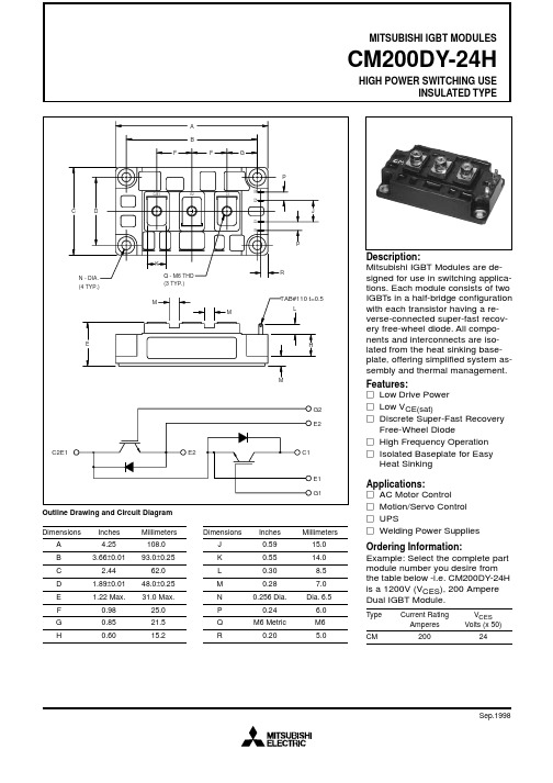
MITSUBISHI IGBT MODULES
CM200DY-24H
德国米铱线激光轮廓扫描传感器样册
5
标准型 高频型 智能型 页码
量程 25 mm
scanCONTROL 2600-25 scanCONTROL 2650-25 scanCONTROL 2610-25 12 - 13
scanCONTROL 26x0 集成控制器,适合自动化应用领域
标准型 高频型 智能型 页码
量程 50 mm
scanCONTROL 2600-50 scanCONTROL 2650-50 scanCONTROL 2610-50 14 - 15
标准型 高频型 智能型 页码
量程 100 mm
scanCONTROL 2600-100 scanCONTROL 2650-100 scanCONTROL 2610-100 16 - 17
标准型 高频型 智能型 页码
量程 25 mm
scanCONTROL 2700-25 scanCONTROL 2750-25 scanCONTROL 2710-25 22 - 23
未过滤的轮廓信息
经过中位值滤波的轮廓信息
测量结果校准 与简单将摄像机与激光线合并使用的系统不 同, scanCONTROL系列轮廓仪输出的不仅是 像素值,还同时输出经过校准的坐标信息。每 支轮廓仪都附带一个校准报告。报告随产品一 同发出,用于验证每支轮廓仪探头的精度水 平。
多尼尔机械公司 - 织布机系列 - 说明书

P2Flexible. Reliable. Efficient.灵活 · 可靠 · 高效 ·FROM FL YING PEOPLE TO FL YING THREADS / 从人类飞行到纱线飞行Design, engineering and production by a single supplierDORNIER is the reliable partner for all requirements relating to any aspect of the production ofa pplication-specific weaving machines for manufacturing high-quality fabrics. Whether a system familyc onsisting of rapier and air-jet weaving machines or a customized turnkey complete line:DORNIER plans, designs and builds everything in-house.HistoryThe world-renowned aircraft manufacturer Dornier began building textile machines after the Second World War. The reason for this change of direction: The Allied Forces had prohibited the company from building airplanes in Germany. In 1950, Lindauer DORNIER GmbH was founded in what remains the company’s headquarters at Lindau-Rickenbach by Peter Dornier, son of the famous aviation pioneer Claude Dornier. The first fruits of the search for a new field of activity there were shuttle weaving machines. But soon afterwards, Lindauer DORNIER GmbH also began making specialty machines, including dryers for the cardboard, paper and construction panel industry. In the mid-1960s, film stretching lines for the packaging and plastic film industry and textile finishing machines for tubular knit goods were added to the product portfolio.The rapier weaving machine, developed in 1967, and the air-jet weaving machine introduced in 1989 represented the most significant milestones in the company’s rise to become Germany’s only weaving machine manufacturer of international standing. The end products made on our weaving machines c omprise extremely high-performance fabrics for airbags, carbon fabrics for composite structures and aramid fabrics for fire-resistant or bullet-proof applications. But equally for the finest silk fabrics, intricate Jacquard items and ultrafine worsteds, the DORNIER system family offers the ideal tool. In 2014 we founded the new DORNIER Composite Systems® product line to continuously deliver new answers for the challenging demands of the dynamic composite industry in the form of innovative production lines for semi-finished composite products of all kinds.设计,构建,生产由单一供应商完成多尼尔作为可靠的合作伙伴,可提供满足各种需求的生产高质量织物的专用织机。
CM400DY-12NF中文资料
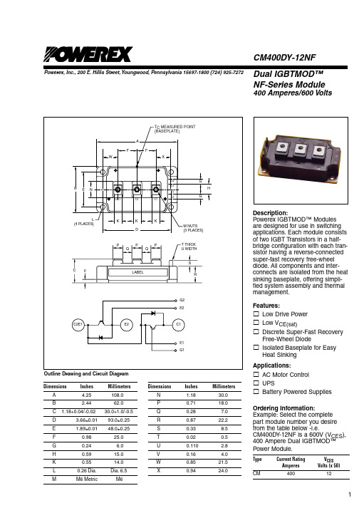
Dual IGBTMOD™NF-Series Module400 Amperes/600 VoltsCM400DY-12NFPowerex, Inc., 200 E. Hillis Street, Youngwood, Pennsylvania 15697-1800 (724) 925-7272Outline Drawing and Circuit Diagram Description:Powerex IGBTMOD™ Modules are designed for use in switching applications. Each module consists of two IGBT Transistors in a half-bridge configuration with each tran-sistor having a reverse-connected super-fast recovery free-wheel diode. All components and inter-connects are isolated from the heat sinking baseplate, offering simpli-fied system assembly and thermal management.Features:£Low Drive Power £Low V CE(sat)£Discrete Super-Fast RecoveryFree-Wheel Diode£Isolated Baseplate for EasyHeat Sinking Applications:£AC Motor Control £UPS£Battery Powered Supplies Ordering Information:Example: Select the complete part module number you desire from the table below -i.e.CM400DY -12NF is a 600V (V CES ), 400 Ampere Dual IGBTMOD™ Power Module.Type Current Rating V CES AmperesVolts (x 50)CM40012Dimensions InchesMillimetersA 4.25 108.0B 2.44 62.0C 1.18+0.04/-0.0230.0+1.0/-0.5 D 3.66±0.01 93.0±0.25 E 1.89±0.0148.0±0.25F 0.98 25.0G 0.24 6.0H 0.59 15.0 K 0.55 14.0 L 0.26 Dia.Dia. 6.5M M6 Metric M6Dimensions InchesMillimetersN 1.18 30.0 P 0.71 18.0 Q 0.28 7.0 R 0.87 22.2 S 0.33 8.5 T 0.02 0.5 U 0.110 2.8 V 0.16 4.0 W 0.85 21.5X 0.94 24.0Powerex, Inc., 200 E. Hillis Street, Youngwood, Pennsylvania 15697-1800 (724) 925-7272CM400DY-12NFDual IGBTMOD™ NF-Series Module400 Amperes/600 VoltsAbsolute Maximum Ratings, T j = 25 °C unless otherwise specifiedRatings Symbol CM400DY-12NF Units Junction Temperature T j–40 to 150 °C Storage Temperature T stg–40 to 125 °C Collector-Emitter Voltage (G-E Short) V CES600 Volts Gate-Emitter Voltage (C-E Short) V GES±20 Volts Collector Current*** (DC, T C' = 92°C) I C400 A mperes Peak Collector Current I CM800* Amperes Emitter Current** (T C = 25°C) I E400 Amperes Peak Emitter Current** I EM800* Amperes Maximum Collector Dissipation (T C = 25°C, T j≤ 150°C) P C1130 Watts Mounting Torque, M6 Main Terminal — 40 in-lb Mounting Torque, M6 Mounting — 40 in-lb Weight — 400 Grams Isolation Voltage (Main Terminal to Baseplate, AC 1 min.) V ISO2500 Volts .Static Electrical Characteristics, T j = 25 °C unless otherwise specifiedCharacteristics Symbol Test Conditions Min. Typ. Max.Units Collector-Cutoff Current I CES V CE = V CES, V GE = 0V —— 1.0 mA Gate Leakage Current I GES V GE = V GES, V CE = 0V —— 0.5µA Gate-Emitter Threshold Voltage V GE(th) I C = 40mA, V CE = 10V 5.0 6.0 7.5 Volts Collector-Emitter Saturation Voltage V CE(sat)I C = 400A, V GE = 15V, T j = 25°C— 1.7 2.2 VoltsI C = 400A, V GE = 15V, T j = 125°C— 1.7— Volts T otal Gate Charge Q G V CC = 300V, I C = 400A, V GE = 15V—1600—nC Emitter-Collector Voltage**V EC I E = 400A, V GE = 0V —— 2.6 VoltsDynamic Electrical Characteristics, T j = 25 °C unless otherwise specifiedCharacteristics Symbol Test Conditions Min. Typ. Max.Unitsiesoes CE GEresInductive d(on)r CC Cd(off)GE1GE2Gfrrrr E*Pulse width and repetition rate should be such that device junction temperature (T j) does not exceed T j(max) rating.**Represents characteristics of the anti-parallel, emitter-to-collector free-wheel diode (FWDi)***Tc' measured point is just under the chips. If this vaule is used, Rth(f-a) should be measured just under the chips .Powerex, Inc., 200 E. Hillis Street, Youngwood, Pennsylvania 15697-1800 (724) 925-7272CM400DY-12NFDual IGBTMOD™ NF-Series Module400 Amperes/600 VoltsThermal and Mechanical Characteristics,T j = 25 °C unless otherwise specifiedCharacteristics Symbol Test Conditions Min. Typ. Max.Units Thermal Resistance, Junction to Case R th(j-c)Q Per IGBT 1/2 Module, T C Reference—— 0.11°C/WPoint per Outline DrawingThermal Resistance, Junction to Case R th(j-c)D Per FWDi 1/2 Module, T C Reference—— 0.19°C/WPoint per Outline DrawingThermal Resistance, Junction to Case R th(j-c)'Q Per IGBT 1/2 Module, —— 0.066°C/WT C Reference Point Under ChipsContact Thermal Resistance R th(c-f)Per 1/2 Module, Thermal Grease Applied — 0.04—°C/W External Gate Resistance R G 1.6 —16 ΩPowerex, Inc., 200 E. Hillis Street, Youngwood, Pennsylvania 15697-1800 (724) 925-7272 CM400DY-12NFDual IGBTMOD™ NF-Series Module400 Amperes/600 Volts。
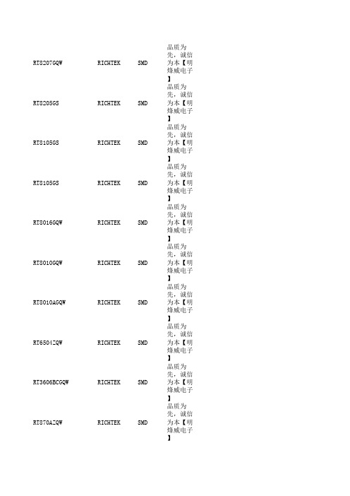
模块大全
RT8207GQW RICHTEK SMD 先,诚信为本【明烽威电子】RT8205GS RICHTEK SMD 品质为先,诚信为本【明烽威电子】RT8105GS RICHTEK SMD 品质为先,诚信为本【明烽威电子】RT8105GS RICHTEK SMD 品质为先,诚信为本【明烽威电子】RT8016GQW RICHTEK SMD 品质为先,诚信为本【明烽威电子】RT8010GQW RICHTEK SMD 品质为先,诚信为本【明烽威电子】RT8010AGQW RICHTEK SMD 品质为先,诚信为本【明烽威电子】RT6504ZQW RICHTEK SMD 品质为先,诚信为本【明烽威电子】RT3606BCGQW RICHTEK SMD 品质为先,诚信为本【明烽威电子】RT870AZQW RICHTEK SMD 品质为先,诚信为本【明烽威电子】R7711AGE RICHTEK SMD 先,诚信为本【明烽威电子】TSM104WAIDT ST SMD STM8L152R8T6ST SMD STK3321-28A SENSORT SMD SKY77916-31SKYWORK SMD SKY77916-21SKYWORK SMD SKY77643-31SKYWORK SMDNUC029LAN Nuvoton TechnologyCorpSMDNQ2102D2EV NXP SMD NQ2102D2EV/C101Y NXP SMD CX93510-12ZP1CONEXAN SMD BQ24735RGRR TI SMD 明烽威电子明烽威电子VVZ110-12IO7IXYS IGBT VVZ24-16IO1IXYS IGBT VVZ24-12IO1IXYS IGBT SKM400GB07E3SEMIKRON IGBT SKKT323/16E SEMIKRON IGBT SKKT323/12SEMIKRON IGBT SKHI01TR SKHI01TR IGBT PM800HSA060MITSUBISHI IGBT MWI150-12T8T IXYS IGBT FRS300BA50SANREX IGBT FP25R12W2T4_B11Infineon IGBT FP25R12W2T4Infineon IGBT CM600DX-24T MITSUBISHI IGBT CM600DX-24S1MITSUBISHI IGBT 明烽威电子MITSUBISHI IGBT CM600DXL-24S MITSUBISHI IGBT CM600DX-24T MITSUBISHI IGBT CM600DX-13T MITSUBISHI IGBT CM600DXLE-24A MITSUBISHI IGBT CM450DX-24T MITSUBISHI IGBT CM450DX-24T#300G MITSUBISHI IGBT2MBI600VN-120-50FUJIELECTRICIGBT2MBI150U4B-120FUJIELECTRICIGBT2MBI150U4B-120-50-C FUJIELECTRICIGBT2MBI150U4B-120-50FUJIELECTRICIGBT2MBI75L-120FUJIELECTRICIGBT2MBI75L-120X3FUJIELECTRICIGBT2MBI150U4A-120-50FUJIELECTRICIGBT2MBI150U4A-120-50-C FUJIELECTRICIGBTVVZ110-14IO7IXYS IGBT VVZ110-12io7IXYS IGBT VVZ24-16I01IXYS IGBT VVZ24-16i01IXYS IGBT 明烽威电子IXYS IGBT VVZ24-12I01IXYS IGBT VUO121-16NO1IXYS IGBT TDB6HK124N16RR Infineon IGBT SKYPER32R SEMIKRON IGBT SKM300MLI066TAT SEMIKRON IGBT SKM40GAH123D SEMIKRON IGBT SKKH106/16E SEMIKRON IGBT SKKH72/16E SEMIKRON IGBT SKKH57/16E SEMIKRON IGBT SKIIP39AHB16V1SEMIKRON IGBT SKIIP26NAB066V1SEMIKRON IGBT SKIIP23NAB126V10SEMIKRON IGBT SKIIP22NAB12T18SEMIKRON IGBT SKIIP13NAB065V1SEMIKRON IGBT SKHI24SEMIKRON IGBT SKHI24R SEMIKRON IGBT SKHI22BH4R SEMIKRON IGBT SKDH146/16-L105SEMIKRON IGBT SK75GAL12T4SEMIKRON IGBT SEMiX603GB12E4p SEMIKRON IGBT SEMiX603GB12E4p SEMIKRON IGBT PSD82/16POWERSE IGBT PM800HSA060MITSUBISHI IGBT PM300DVA120MITSUBISHI IGBT PM300DSA120MITSUBISHI IGBT PK200FG160SANREX IGBT PD100KN16NIEC IGBT MMG100J120UZ MACMIC IGBT MDD255-20N1IXYS IGBT MCC225-16IO1IXYS IGBT K220A4002TYCO IGBT K220A4003TYCO IGBT K220A4001TYCO IGBT GD50HFL120C1S STARROW IGBTFS150R06KE3Infineon TechnologiesIGBT明烽威电子Infineon TechnologiesIGBTFS100R12KS4TechnologiesIGBTFS15R12YT3Infineon TechnologiesIGBTFF100R12MT4Infineon TechnologiesIGBTFD200R12KE3Infineon TechnologiesIGBTF4-75R12MS4Infineon TechnologiesIGBT明烽威电子Infineon TechnologiesIGBTF3L150R07W2E3Infineon TechnologiesIGBTF3L150R07W2E3_B11Infineon TechnologiesIGBTDDB6U84N16RR Infineon TechnologiesIGBTCM500HA-34A MITSUBISHI IGBT CM500HA-34A MITSUBISHI IGBT CM300DY-12H MITSUBISHI IGBT CM200DY-24A MITSUBISHI IGBT CM200DY-12H MITSUBISHI IGBTBSM150GB120DN2Infineon TechnologiesIGBTBSM100GD120DN2Infineon TechnologiesIGBTAPT60GF120JRD APT IGBTA50L-0001-0326FUJIELECTRICIGBT6MBP30RTB060-50FUJIELECTRICIGBT2SD315AI CONCEPT IGBT2MBI100U4H-170FUJIELECTRICIGBT2MBI75S-120FUJIELECTRICIGBT2MBI75N-120FUJIELECTRICIGBT2A200HB17C2L TechnologiesIGBT1MBI300N-120FUJIELECTRICIGBT2A200HB17C2L Infineon TechnologiesIGBTSKM300GB12T4SEMIKRON IGBT SKM300GA123D SEMIKRON IGBT SKM150GB128D SEMIKRON IGBT SKM150GB12T4G SEMIKRON IGBT SKM100GB176D SEMIKRON IGBT SKM100GB123D SEMIKRON IGBT SKM75GB176D明烽威电子IGBT SKM75GB123D明烽威电子IGBT SKKE600F12SEMIKRON IGBT SKKE330F17SEMIKRON IGBT SKKD162/16明烽威电子IGBT SKKD106SEMIKRON IGBT SKKD106/16E明烽威电子IGBT SKKD81SEMIKRON IGBT SKKD81/14SEMIKRON IGBT 明烽威电子SEMIKRON IGBT SKKD81/04SEMIKRON IGBT SKKD81/18明烽威电子IGBT SKKD81/14SEMIKRON IGBT SKET740明烽威电子IGBT SKET740/22GH4SEMIKRON IGBT SKET740/18E明烽威电子IGBT SKET740/12SEMIKRON IGBT SKET740/18GH4SEMIKRON IGBT SKET740/22GH4SEMIKRON IGBT SKD146/16-L140T4SEMIKRON IGBT SK75GAR12T4明烽威电子IGBT SK60GAL125明烽威电子IGBT SK35GD126ET SEMIKRON IGBT PSD82/16POWERSE IGBT PM200DVA120明烽威电子IGBTPM150CVA120MITSUBISHI 明烽威电子PM50RLB120MITSUBISHI IGBT 明烽威电子MITSUBISHI IGBT PM50B6LA060明烽威电子IGBT PM50B5LA060MITSUBISHI IGBT PM30CTJ060MITSUBISHI IGBT MWI100-12T8T IXYS IGBT MWI100-12E8IXYS IGBT MMF200ZB040DK1C MACMIC IGBT MMF200ZB040DK1C MACMIC IGBT MIG50Q7CSB1X MITSUBISHI IGBTMDST100-16GUERTE IGBT MDC160-16IXYS IGBT GD400HFL120C2S STARPOW IGBT GD300HFL120C2S STARPOW IGBTFZ1200R33HE3Infineon TechnologiesIGBTFT150R12KE3G Infineon TechnologiesIGBTFT150R12KE3G Infineon TechnologiesIGBTFS300R12KE3Infineon TechnologiesIGBTFS200R12PT4Infineon TechnologiesIGBTFP75R12KT4Infineon TechnologiesIGBTFP50R12KT4Infineon TechnologiesIGBTFP50R12KT3Infineon TechnologiesIGBTFF1200R17KE3Infineon TechnologiesIGBTFF450R06ME3Infineon TechnologiesIGBTFF400R33KF2C Infineon TechnologiesIGBTFF150R12RT4明烽威电子IGBTF4-75R12MS4Infineon TechnologiesIGBTDP450B1700T102821DANFOSS IGBT DM2G100SH6A DAWIN IGBT DIM400GDM33-F076DYNEX IGBT DIM400GDM33-F000DYNEX IGBT DH2F100N4S DAWIN IGBTDDB6U104N16RR Infineon TechnologiesIGBTCM600DU-24F MITSUBISHI IGBT CM450DX-24S1MITSUBISHI IGBTCM400HU-24F MITSUBISHI IGBT CM400DU-24F MITSUBISHI IGBT CM400DU-12F MITSUBISHI IGBT CM300DU-24NFH MITSUBISHI IGBT CM200DY-12NF MITSUBISHI IGBT CM150RL-24NF MITSUBISHI IGBT CM150DC1-24NFM MITSUBISHI IGBT CM100TX-24S MITSUBISHI IGBT BSM150GT120DN2明烽威电子IGBTBSM50GD170DL Infineon TechnologiesIGBTBSM10GP120Infineon TechnologiesIGBT7MBR15SA120-50FUJIELECTRICIGBT6MBI50S-120FUJIELECTRICIGBT4MBI400VF-120R-50FUJIELECTRICIGBT2SD106AI-17CONCEPT IGBT2MBI450VN-120-50FUJIELECTRICIGBT2MBI200U2A-060-50FUJIELECTRICIGBT1MBI400NA-120-02FUJIELECTRICIGBT1MBI400NA-120FUJIELECTRICIGBT1MBI300SA-120B-52FUJIELECTRICIGBT1MBI300N-120FUJIELECTRICIGBT明烽威电子明烽威电子明烽威电子明烽威电子明烽威电子明烽威电子SKKH330/16E明烽威电子VUO98-16NO7IXYSVUO98-12N07IXYSVUO98-08NO7IXYSVUO98-18NO7IXYSFF200R17KE3Infineon Technologie s2A75HB12C1U Infineon Technologie sFP40R12KT3G Infineon Technologie sFP40R12KT3TechnologiesSKIIP39AHB16V1SEMIKRON CM300DY-12NF MITSUBISHI CM300DY-24H MITSUBISHI CM300DY-24A明烽威电子FS450R12KE3Infineon Technologie sFS450R17KE3Infineon Technologie sP089A2009明烽威电子P089A2004TYCOP089A2001TYCOP080A2006TYCOFS450R12KE4Infineon Technologie sFS450R12KE3Infineon Technologie sSKM145GB128D明烽威电子明烽威电子SEMIKRON SKM145GB123D SEMIKRON SKKH460/20E H4SEMIKRON SKKH460/22EH4明烽威电子SKKH460/16SEMIKRON SKKH460/12E SEMIKRON 2SC0435T2A0CONCEPT2SC0435T2A0-17CONCEPTFF200R12KT4Infineon Technologie sSKKT162/16E明烽威电子SKKT162/12E SEMIKRONTD142N16KOF Infineon Technologie sSKIIP03NAC126V1SEMIKRON SKIIP03NAC12T4V1明烽威电子SKIIP03NAC066V3SEMIKRON FB15R06KL4EUPECFB15R06KL4-B1EUPECFB15R06KL4_B1EUPECFZ1500R33HE3Infineon Technologie sFZ1500R33HL3Technologies2MBI1400VXB-170-54FUJI ELECTRIC2MBI1400VXB-170P-5明烽威电子2MBi1400VXA-170E-50FUJI ELECTRIC2MBI1400VXB-120P-50FUJI ELECTRIC2MBI1400VXA-170-50FUJI ELECTRIC2MBI1400VXB-120P-54FUJI ELECTRICPM50RLB120明烽威电子PM50RLB060MITSUBISHI MG200J2YS50TOSHIBA CM150G6X-24S1MITSUBISHIBSM150GB170DN2Infineon Technologie sBSM150GB170DLC Infineon Technologie sBSM150GB120DN2Infineon Technologie sBSM150GB60DLC Infineon Technologie sBSM150GB120DN2Infineon Technologie s2A200HB17C2L Infineon Technologie sFD200R12KE3Infineon Technologie sMCC255-16IO1IXYS2MBI650VXA-170E-50FUJI ELECTRICF3L100R07W2E3 B11Infineon Technologie sF3L100R07W2E3Infineon Technologie sDDB6U84N16RR EUPEC DDB6U84N16RR EUPEC2MBI300VN-120-5FUJI ELECTRICVUO121-16NO1IXYSCM450DX-24MITSUBISHI CM450DX-24T MITSUBISHIDD260N16K Infineon Technologie sSKKD162SEMIKRON SKKD162/16SEMIKRON SKKD162/12SEMIKRON GD35PJT120L3S STARPOWFF400R33KF2C Infineon Technologie sRM1500HE-66F MITSUBISHI 1SD536F2Concept1SD536F2-5SNA1500E330300Concept1SD536F2-5SNA2400E17010Concept1SD536F2-FX800R33KF2Concept1SD536F2-MIO2400-17E10Concept HAT1500-S LEMIKCM30F60GA LS2MBI1400VXB-120P-50FUJI ELECTRIC2MBI1400VXB-170P-54FUJI ELECTRIC2MBI1400VXB-170P-54FUJI ELECTRICBG200B12UX2S-I BYD BG200B12UY2-I BYDBSM150GB60DLC Infineon Technologie sBSM150GB60DLC。
线缆制程辅助仪器系列
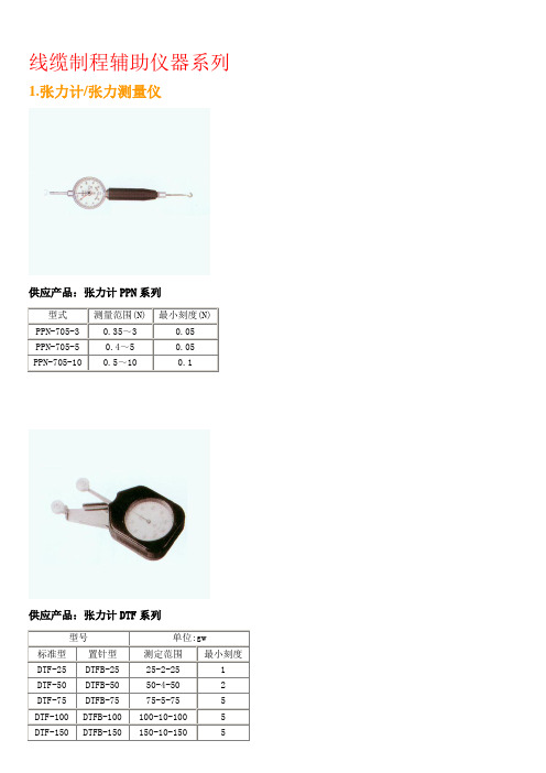
线缆制程辅助仪器系列1.张力计/张力测量仪供应产品:张力计PPN系列供应产品:张力计DTF系列供应产品:张力计TK系列供应产品:张力计DTN系列供应产品:T-101/102张力测量仪T-101、T-102系列指针式张力计 Dial Type Tension Gauge 特点:※ 在纺织的过程中,纱支的张力控制十分重要,横河牌张力计配置有三个滑轮,可以在动态的纺织状态下,方便快捷的测读纱支所呈现的张力。
※ 亦可用于电线或金属丝的张力测试。
※ 张力计的转动部份由蓝宝石轴承构成,并配有阻尼器,可完全消除自我振动及仪表本身造成的阻力,增加测读结果的可靠性。
供应产品:ZF2、ZD2、DX2系列张力计供应产品:DXE/V/P/F/R 系列张力计供应产品:DN系列张力计供应产品:ZE及ET系列数显张力计供应产品:DT系列数显张力计供应产品:TS在线张力计供应产品:HD302指针式张力仪系列测定制线、整经、捻线、漆包线、铜丝等线材料在移动或静止状态下的张力。
主要技术参数1、测定范围:HD302-05 0~50(cN)HD302-10 0~100(cN)HD302-20 0~200(cN)HD302-30 0~300(cN)2、度盘指针转动有效角度:270°3、外形尺寸:153×58×65mm(L×W×H)4、在线测量速度:6000米/min供应产品:SHIMPO数显张力仪SHIMPO数显张力仪 DTMB DTMX适用范围:线、钢丝、铜丝、光纤线、碳纤线、磁带、胶卷一个测量计可以浊五种不同的金属丝1、细线;2、钢线;3、铜线和其他两种标本金属丝。
通过结合使用设置开关,金属丝型号选择开头或范围开关实现转变。
有多种可选模式:张力测量范围200至20;每种模式都适于各种类型;标准、高性能型。
DTM □--0.2/0.5/1/2/2.5/5B/10B/20BX:提供输出功能B:无输出功能的标准类型供应产品:HD302指针式张力仪系列测定制线、整经、捻线、漆包线、铜丝等线材料在移动或静止状态下的张力。
IGBT模块型号参数大全

各品牌IGBT模块型号参数大全
一.IGBT模块
1.富士IGBT N系列(高速,低导通压降) P系列 S系列
2.EUPEC(西门子)IGBT 电流参数据库85C标称
DN2:标准系列
KE3:低导通压降系列
KS4:高速系列
DLC:低导通压降系列
PIM:三相桥+七单元+NTC GP系列 FP系列
大功率IGBT模块
CHOPPER=IGBT+二极管 GAL=IGBT+C接二级管 GAR=IGBT+E接二极管
3.三菱IGBT模块
H系列
H系列
A系列
NF系列
U系列
MDX系列
MD3:单相桥+六单元 MD1:三相桥+六单元 MD:三相桥+七单元
E3系列
4.SEMIKRON(西门康)IGBT
低损耗型(频率:0-4KHZ)
沟道式超低损耗型(频率0-6KHZ)
标准系列(频率:4-12KHZ)
软穿通式高速型(频率:5-20KHZ)
CHOPPER GAL=IGBT+C串二极管 GAR=IGBT+E串二极管
MiniSKiiP系列
SEMIX系列
SEMITOP系列
GAL=IGBT+C串二极管 GAR=IGBT+E串二极管
SKIM系列
超高速型(频率:30KHZ)
大功率集成装置(SEMISTACK)
5.IXYS(艾赛斯)IGBT
ID=IGBT+C串二极管 DI=IGBT+串二极管
6.APT IGBT
7.DYNEX IGBT
8.ABB IGCT
模块的基本参数,IGBT模块中文资料参数.。
IXYS等 IGBT模板各系列参数大全
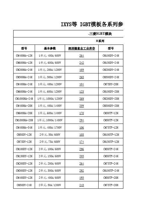
基本参数 2单元,150A/600V 2单元,200A/600V 2单元,300A/600V 2单元,400A/600V 2单元,600A/600V 2单元,100A/12044 258
型号 CM50TL-24NF CM75TL-24NF CM100TL-24NF CM150TL-24NF CM200TL-24NF CM75TL-12NF
CM150DY-24NF CM200DY-24NF CM300DY-24NF CM400DY-24NF CM600DY-24NF CM75TL-12NF CM100TL-12NF CM150TL-12NF CM200TL-12NF
2单元,150A/1200V 2单元,200A/1200V 2单元,300A/1200V 2单元,400A/1200V 2单元,600A/1200V 6单元,75A/600V 6单元,100A/600V 6单元,150A/600V 6单元,200A/600V
294 259 193 171 227 249 276 251 115
CM100RL-12NF CM150RL-12NF CM200RL-12NF CM50RL-24NF CM75RL-24NF CM100RL-24NF CM150RL-24NF CM200RL-24NF
U系列 型号 CM600HU-12H CM400HU-24H CM600HU-24H CM75DU-12H CM100DU-12H CM150DU-12H CM200DU-12H CM300DU-12H CM400DU-12H CM50DU-24H CM75DU-24H CM100DU-24H 基本参数 1单元,600A/600V 1单元,400A/1200V 1单元,600A/1200V 2单元,75A/600V 2单元,100A/600V 2单元,150A/600V 2单元,200A/600V 2单元,300A/600V 2单元,400A/600V 2单元,50A/1200V 2单元,75A/1200V 2单元,100A/1200V 深圳德意志工业库存 268 228 185 173 106 296 258 120 238 266 187 242 型号 CM150DU-24H CM200DU-24H CM300DU-24H CM75BU-12H CM100BU-12H CM75TU-12H CM100TU-12H CM150TU-12H CM200TU-12H CM50TU-24H CM75TU-24H CM100UF-24H
D10,D11,D12系列放大器,光纤

供电电压 10 ~ 30V dc 10 ~ 30V dc 10 ~ 30V dc
输出形式
互补型 NPN
互补型 PNP
互补型 NPN
互补型 PNP
互补型 NPN
互补型 PNP
过量增益
直反式检测性能基于90%反射率的白测试卡
1000
E X C E 100 S S
D11FPG, D11FPB and D11FPW Series
Opposed Mode Plastic Fibers
G 10
A
I
N
PIT26U Fibers
1
PIT46U Fibers
0.1 mm 0.004 in
1.0 mm 0.04 in
10 mm 0.4 in
DISTANCE
PIT66U Fibers
100 mm 4.0 in
1000
E X C E 100 S S
D10专家型系列
• Email: sensors@
53 美国邦纳工程国际有限公司
D10 Series
光纤放大器—— D10 专家型TM系列-双开关量输出
54 美国邦纳工程国际有限公司
光纤放大器 —— D10 系列
G 10 A I N
1
D11FPG, D11FPB and D11FPW Series Diffuse Mode Plastic Fibers
PBT66U Fibers
PBT46U Fibers
1.0 mm 0.04 in
10 mm 0.4 in
100 mm 4.0 in
DISTANCE
1000 mm 40 in
• 输出响应时间500µs(0.5ms) • LED可显示上电,输出过载,光路瞄准及临
CM200DY-24H中文资料

Units °C °C Volts Volts Amperes Amperes Amperes Amperes Watts N·m N·m Grams Vrms
Static Electrical Characteristics, Tj = 25 °C unless otherwise specified
COLLECTOR-EMITTER SATURATION VOLTAGE CHARACTERISTICS (TYPICAL)
400
COLLECTOR CURRENT, IC, (AMPERES) COLLECTOR CURRENT, IC, (AMPERES)
400
COLLECTOR-EMITTER SATURATION VOLTAGE, VCE(sat), (VOLTS)
Sep.1998
元器件交易网
MITSUBISHI IGBT MODULES
CM200DY-24H
HIGH POWER SWITCHING USE INSULATED TYPE
OUTPUT CHARACTERISTICS (TYPICAL)
TRANSFER CHARACTERISTICS (TYPICAL)
7 5 3 2
Tj = 25°C
102
Cies
8
IC = 400A
101
Coes
6
FREE-WHEEL DIODE FORWARD CHARACTERISTICS (TYPICAL)
CAPACITANCE VS. VCE (TYPICAL)
10
COLLECTOR-EMITTER SATURATION VOLTAGE, VCE(sat), (VOLTS)
103
infinite M200使用手册-酶标仪
文件版本:1.2
说明:本手册并非 Tecan infinite 200 操作手册的中文版,
仅供 Tecan infinite 200 酶标仪使用者参考。仪器的性能和 使 用 只 能 以 Tecan infinite 200 原 厂 说 明 书 、 Tecan Magellan 软件原厂说明书、Tecan I-Control 软件原厂说明 书、Tecan NanoQuant 原厂说明书为准。因不恰当的理解 和使用本手册带来的经济损失和知识产权纠纷,由手册使用 者自行承担,本手册编制者不承担任何连带责任。
附录 1 附 1 加液器的使用方法 附 1.1 加液器概述………………………………………………………………47 附 1.2 加液器的使用……………………………………………………………48 附 1.2.1 加液器使用注意事项…………………………………………………48 附 1.2.2 加液器的维护(Service)指令 ……………………………………50 附 1.2.3 加液器的加液操作……………………………………………………55 附 1.3 加液器的维护……………………………………………………………59
长:457mm 宽:425mm 高:253mm
14Kg 15.8Kg
12
环境条件 环境温度 操作时 非操作时 相对湿度 过压级别 污染级别
用途 嘈声水平 处置方式
15℃--30℃ 59℉--86℉ -20℃--+60℃ –4℉--+140℉ 小于 90% 无冷凝 Ⅱ 2 实验室用仪器 <60dBA 电子废弃物(传染性废弃物)
253mm14kg158kg12环境条件环境温度操作时非操作时相对湿度过压级别污染级别用途嘈声水平处置方式1530598620604140小于90无冷凝实验室用仪器60dba电子废弃物传染性废弃物32荧光波长范围m200f200标准型pmt激发发射增强型pmt激发发射读数时间延迟时间230nm850nm1nm步进230nm850nm230nm600nm330nm600nm230nm850nm280nm850nm202000s02000s增益值设置测量范围手动方式优化方式从单孔计算1255自动自动060000rfu060000rfu060000rfu13荧光强度顶部检测性能液体体积ul阅读次数荧光检测极限pm一致性25nm荧光素重复性25nm荧光素962002520pm3cv2荧光强度底部检测性能液体体积ul阅读次数荧光检测极限pm一致性25nm荧光素重复性25nm荧光素9620025100pm3cv233荧光偏振仅f200波长范围标准型pmt激发发射增强型pmt激发发射标准滤光片激发发散300nm600nm330nm600nm300nm850nm330nm850nm48520nm水平垂直53525nm水平垂直14读数时间延迟时间偏振精度202000s02000s5mp1nm荧光素增益值设置测量范围手动方式优化方式从单孔计算1255自动自动060000rfu060000rfu060000rfu34光吸收波长范围m200f200测量范围230nm1000nm1nm步进230nm1000nm03od光吸收检测性能准确性02od准确性23od一致性od重复性02od重复性23od线性范围02od96110mod253cv110mod2509981535辉光型发光波长范围线性动态范围检测时间串扰率黑板测量范围光稀释380nm600nm10扩展的动态范围120000ms00110101不稀释atp辉光型发光检测性能液体体积ul单孔检测时间msatp检测极限9620010003fmol孔36闪光型发光波长范围测量范围检测时间串扰率黑板光稀释atp检测极限380nm600nm10120000ms001101不稀释80amol孔1637双色发光如bret波长范围动态范围检测时间120000ms双色各自设定96和384图1
V 12-2型号迪菲电子光电开关系列产品介绍说明书

V 12-2Detecting objectson conveyor belts using VS/VE 12-2through-beam photo-electric switches.▼VL 12-2 photoelectric reflex switches canalso be used for the reliable detection of reflective surfaces, for example film-wrapped cardboard boxes.VT 12-2 photo-electric proximity switches used to ensure that waste is rolled up correctly when paper and film strips are cut.Is an objectpresent or not? The VT 12-2 photo-electric proximity switch provides the answer.▼▲▲VT 12T-2, Scanning distance 115 mm/340 mm115 mm Scanning distance340 mm Scanning distance 0 (mm)204060801001207025501152100210 (mm)501001502002503003502180200034023002112Scanning distance on white, 90 % remission Scanning distance on grey, 18 % remissionOperating distance Scanning distance, max. typical(mm)50100150200250300100101O p e r a t i n g r e s e r v eScanning distance max. typical Operating distanceVT 12(T)-2300 mm12(mm)10060802040100110O p e r a t i n g r e s e r v eOperating distance 21Scanning distance max. typical VT 12(T)-2100 mmScanning distance, max. typical 1)0... 115 mm 0 ... 340 mm Operating distance 1)2... 100 mm 2 ... 300 mmSensitivity setting Manual, per Teach-in buttonElectronic, per control input C (0 V)2)Light source 3), light type LED, infrared lightLight spot diameterApprox. 20 mm at 100 mm Approx. 28 mm at 300 mm Angle of dispersion of senderApprox. 11.4°(SD = max.), Approx. 22.6°(SD = 1/2 max.)Approx. 5.3°(SD = max.),Approx. 11.2°(SD = 1/2 max.)Supply voltage V S 10 ... 30 V DC 4)Ripple 5)≤10%Current consumption 6)≤20 mA Switching outputs Q: PNP Q: NPN Output current l A max.≤100 mASwitching mode Light-/Dark-switching selectable 2)Response time 7)≤1.25 ms Switching frequency max.8)400/sConnection typesCable 9)PVC, 2 m, 4 x 0.14 mm 2, Ø 3.75 mm PlugM12, 4-pinVDE protection class 10)VCircuit protection 11)A, B, C, D Enclosure ratingIP 67Ambient temperature T A Operation –25 °C ... +70 °C Storage –25 °C ... +70 °C WeightWith cable Approx. 54 g With plug Approx. 18 gHousing materialHousing:Nickel-coated brass/PA Optics:PC1)Object to be detected with 90%remission (relating to standard white in acc. with DIN 5033); 100 x 100 mm2)Controll input C – L.ON/D.ON and – external Teach-inC = open: light-switching L.ON C = + V S : dark-switching D.ONC = 0 V: Sensitivity setting per “externalTeach-in” active3)Average service life 100,000 h at T A = +25°C 4)Limit values5)May not exceed or fall short of V S tolerances 6)Without load7)Signal transit time with resistive load8)With light/dark ratio 1:19)Do not bend below 0°C 10)Reference voltage 50 V DC11)A =V Sconnections reverse-polarityprotectedB =Inputs and output reverse-polarityprotectedC =Interference pulse suppressionD =Outputs overload and short-circuitprotectedTechnical dataVT 12T-2P 112P 410N 112N 410P 132P 430N 132N 430TypeOrder no.VT 12T -2P 112 6 026 211VT 12T -2P 410 6 026 212VT 12T -2N 112 6 026 209VT 12T -2N 410 6 026 210VT 12T -2P 132 6 026 215VT 12T -2P 430 6 026 216VT 12T -2N 132 6 026 213VT 12T -2N 4306 026 214Order information0 (m)0.5 1.0 1.5 2.0 2.5 3.0Operating range Scanning range, max. typical0 2.50.03 2.00 2.30.03 1.80.90.10.7 2.80.03 2.323410.1 ... 0.7 mReflective tape Diamond GradePL 50 A/PL 40 A/P 25040.03 ... 1.8 m 3 C 1100.03 ... 2.0 m 2PL 80 A 0.03 ... 2.3 m1Reflector type Operating range VL 12-210001001011.01.52.02.50.5(m)O p e r a t i n g r a n g eOperating rangeReflectorC 110Scanning range, max. typical V L 12-22Scanning range, max.typ./reflector 0.03... 2.8 m/PL 80 A Operating range 0.03... 2.3 m/PL 80 A Sensitivity settingNot availableLight source 1), light type LED, red light, with polarization filter Light spot diameterApprox. 80 mm at 2 m Angle of dispersion of sender Approx. 2.3°(SR = max.), Approx. 6.3°(SR = 1/2 max.)Supply voltage V S 10 … 30 V DC 2)Ripple 3)≤10%Current consumption 4)≤20 mASwitching outputsQ: PNP Q: NPN Output current l A max.≤100 mASwitching mode Light-/Dark-switching selectable 5)Response time 6)≤1.25 ms Switching frequency max.7)400/sConnection types Cable 8)PVC, 2 m, 4 x 0.14 mm 2, Ø 3.75 mm PlugM12, 4-pinVDE protection class 9)VCircuit protection 10)A, B, C, D Enclosure ratingIP 67Ambient temperature T A Operation –25 °C ... +70 °C Storage –25 °C ... +70 °CWeightWith cable Approx. 54 g With plug Approx. 18 gHousing materialHousing: Nickel-coated brass/PA Optics: PC1)Average service life 100,000 h at T A = +25°C 2)Limit values3)May not exceed or fall short of V S tolerances 4)Without load5)L/D switching type control line L/D =open (not assigned)dark-switching D.ONL/D =+ V S : light-switching L.ON L/D =0 V: dark-switching D.ON6)Signal transit time with resistive load 7)With light/dark ratio 1:18)Do not bend below 0°C 9)Reference voltage 50 V DC10)A =V S connections reverse-polarityprotectedB =Inputs and output reverse-polarityprotectedC =Interference pulse suppressionD =Outputs overload and short-circuitprotectedTechnical dataVL 12-2P 132P 430N 132N 430Scanning range and operating reserveType Order no.VL 12-2P 132 6 026 219VL 12-2P 430 6 026 220VL 12-2N 132 6 026 217VL 12-2N 4306 026 218Order informationVS/VE 12-2100010010123451(m)O p e r a t i n g r e s e r v eOperating rangeScanning range, max. typical V S/V E 12-20 (m) 1.0 2.0 3.0 4.0 5.0 6.0Operating range Scanning range, max. typical5.04.0Scanning range, m a x .t yp .0... 5.0 m O p e r at in g r a n ge 0... 4.0 m Se n s i t ivi t y sett in gN ot a v a il a bl e Light source 1), light type L ED, infr a r e d li g h tLi g h t s p ot di a m ete rAppr o x . 100 mm at 4 m An g l e o f di s p e r s i o n o f se nd e r Appr o x . 1.4°(S R = m a x .), An g l e o f di s p e r s i o n o f r ece iv e r Appr o x . 4.5°(S R = 1/2 m a x .)Supply voltage V S 10 … 30 V DC 2)Rippl e 3)≤10%C urr e n t co n s ump t i o n 4)≤20 mASwitching outputs Q : PNP Q : NPN O u t pu t c urr e n t l A m a x .≤100 mAS wi tc hin g m o d e Li g h t-/Da rk -s wi tc hin g se l ecta bl e 5)R es p o n se t im e 6)≤2.0 m s S wi tc hin g fr e qu e n c y m a x .7)250/sConnection typesCa bl e 8) se nd e r V S 12-2 PV C, 2 m , 2 x 0.14 mm 2, Ø 3.75 mm Ca bl e 8) r ece iv e r V E 12-2 PV C, 2 m , 4 x 0.14 mm 2, Ø 3.75 mm Plu gM12, 4-pinVDE protection class 9)VCircuit protection 10)A , B, C, D Enclosure ratingIP 67Ambient temperature T A O p e r at i o n –25 °C ... +70 °C Sto r age –25 °C ... +70 °C WeightWi t h ca bl e V S a nd V E eac h a ppr o x . 54 g Wi t h plu g V S a nd V E eac h a ppr o x . 18 g Housing materialH o u s in g : Ni c k e l -coate d br ass /PA O p t i cs :P C1)Av e r age se rvi ce lif e 100,000 h at T A = +25°C 2)Limi t v a lu es3)M a y n ot e x cee d o r f a ll s h o r t o f V S to l e r a n ces 4)Wi t h o u t l oa d5)L/D s wi tc hin g t yp e co n t r o l lin e L/D =o p e n (n ot ass i g n e d)d a rk -s wi tc hin g D.O NL/D =+ V S : li g h t-s wi tc hin g L .O N L/D =0 V: d a rk -s wi tc hin g D.O N6)S i g n a l t r a n s i t t im e wi t h r es i st iv e l oa d 7)Wi t h li g h t /d a rk r at i o 1:18)Do n ot b e nd b e l o w 0°C 9)R e f e r e n ce v o l tage 50 V DC10)A =V S co nn ect i o n s r e v e r se-p o l a ri t ypr otecte dB =Inpu ts a nd o u t pu t r e v e r se-p o l a ri t ypr otecte dC =In te rf e r e n ce pul se s uppr ess i o nD =O u t pu ts o v e rl oa d a nd s h o r t-c ir c ui tpr otecte d11)Th e o rd e r n o. co n ta in s t r a n s mi tte r a nd r ece iv e r (= p a ir).Technical dataV S /V E 12-2P 132P 430N 132N 430Scanning range and operating reserveType 11)Order no.11)V S /V E 12-2P 132 6 026 223V S /V E 12-2P 430 6 026 224V S /V E 12-2N 132 6 026 221V S /V E 12-2N 4306 026 222Order information。
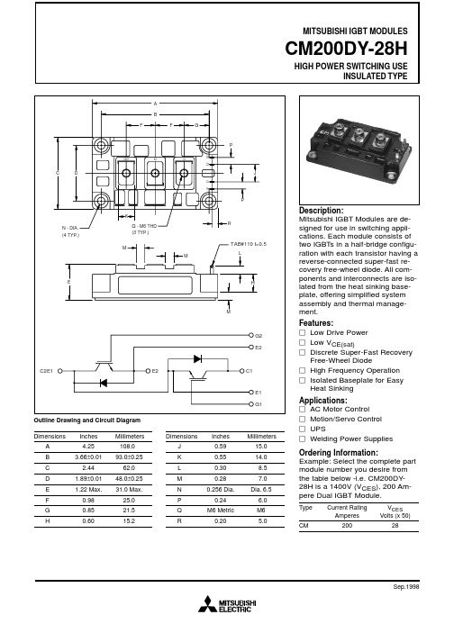
CM200DY-28H中文资料
0 0 4 8 12 16 20
GATE-EMITTER VOLTAGE, VGE, (VOLTS)
0 0 80 160 240 320 400
COLLECTOR-CURRENT, IC, (AMPERES)
COLLECTOR-EMITTER SATURATION VOLTAGE CHARACTERISTICS (TYPICAL)
** Pulse width and repetition rate should be such that device junction temperature rise is negligible.
Dynamic Electrical Characteristics, Tj = 25 °C unless otherwise specified
TAB#110 t=0.5
L
E
H
M
Description: Mitsubishi IGBT Modules are designed for use in switching applications. Each module consists of two IGBTs in a half-bridge configuration with each transistor having a reverse-connected super-fast recovery free-wheel diode. All components and interconnects are isolated from the heat sinking baseplate, offering simplified system assembly and thermal management. Features: Low Drive Power Low VCE(sat) Discrete Super-Fast Recovery Free-Wheel Diode High Frequency Operation Isolated Baseplate for Easy Heat Sinking Applications: AC Motor Control Motion/Servo Control UPS Welding Power Supplies Ordering Information: Example: Select the complete part module number you desire from the table below -i.e. CM200DY28H is a 1400V (VCES), 200 Ampere Dual IGBT Module.
CM200DY-24A中文资料
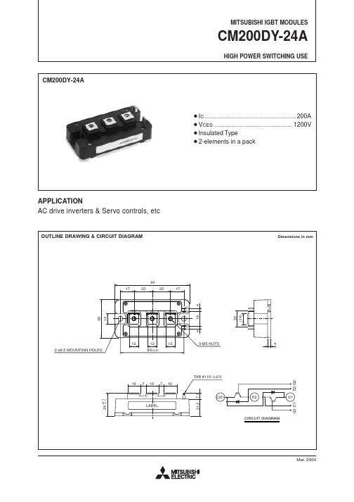
V CE = V CES , V GE = 0V V GE = V GES , V CE = 0V T j = 25°CT j = 125°C V CC = 600V, I C = 200A, V GE = 15VV CC = 600V, I C = 200A V GE1 = V GE2 = 15VR G = 1.6Ω, Inductive load switching operation I E = 200AI E = 200A, V GE = 0V IGBT part (1/2 module)*1FWDi part (1/2 module)*1Case to fin, Thermal compound Applied (1/2 module)*1,*2I C = 20mA, V CE = 10VI C = 200A, V GE = 15VV CE = 10V V GE = 0V1200±202004002004001340–40 ~ +150–40 ~ +12525002.5 ~ 3.53.5 ~ 4.5310HIGH POWER SWITCHING USEV V A A W °C °C V N • m g10.53.0—3530.68—130100450350150—3.80.0930.17—21mA µA nF nC ns µC V °C/W Ω——2.12.4———1000—————9.0———0.022———————————————————1.67V V 68ns I CES I GES C ies C oes C res Q G t d(on)t rt d(off)t ft rr (Note 1)Q rr (Note 1)V EC(Note 1)R th(j-c)Q R th(j-c)R R th(c-f)R GSymbol ParameterV GE(th)V CE(sat)*1 : Tc, Tf measured point is just under the chips.*2 : Typical value is measured by using Shin-etsu Silicone “G-746”.Note 1. I E , V EC , t rr & Q rr represent characteristics of the anti-parallel, emitter to collector free-wheel diode (FWDi).2. Pulse width and repetition rate should be such that the device junction temp. (T j ) does not exceed T jmax rating.3. Junction temperature (T j ) should not increase beyond 150°C.Collector-emitter voltage Gate-emitter voltage Maximum collector dissipation Junction temperature Storage temperature Isolation voltage WeightG-E Short C-E ShortDC, T C = 84°C *1Pulse (Note 2)Pulse(Note 2)T C = 25°C *1Main terminal to base plate, AC 1 min.Main terminal M5Mounting holes M6Typical valueSymbol ParameterCollector current Emitter currentTorque strength ConditionsUnit Ratings V CES V GES I C I CMI E (Note 1)I EM (Note 1)P C (Note 3)T j T stg V iso———Unit Typ.Limits Min.Max.Test conditionsELECTRICAL CHARACTERISTICS (Tj = 25°C)ABSOLUTE MAXIMUM RATINGS (Tj = 25°C)Collector cutoff current Gate-emitter threshold voltageGate leakage currentCollector-emitter saturation voltageInput capacitance Output capacitanceReverse transfer capacitance Total gate charge Turn-on delay time Turn-on rise time Turn-off delay time Turn-off fall timeReverse recovery time Reverse recovery charge Emitter-collector voltage Contact thermal resistance External gate resistanceThermal resistanceHIGH POWER SWITCHING USEHIGH POWER SWITCHING USEHIGH POWER SWITCHING USE。
赛米控丹佛斯 SEMITRANS IGBT模块 SKM400GB12T4 数据表

SEMITRANS ®3Fast IGBT4 ModulesSKM400GB12T4Features•IGBT4 = 4. generation fast trench IGBT (Infineon)•CAL4 = Soft switching 4. generation CAL-diode•Isolated copper baseplate using DBC technology (Direct Bonded Copper) •Increased power cycling capability •With integrated gate resistor•For higher switching frequenzies up to 20kHz•UL recognized, file no. E63532Typical Applications*•AC inverter drives •UPS•Electronic welders at fsw up to 20 kHzRemarks•Case temperature limited to T c = 125°C max.•Recommended T op = -40 ... +150°C •Product reliability results valid for T j = 150°CAbsolute Maximum Ratings SymbolConditions Values UnitIGBT V CES T j =25°C 1200V I C T j =175°CT c =25°C 616A T c =80°C474A I Cnom 400A I CRMI CRM = 3xI Cnom 1200A V GES -20...20V t psc V CC =800V V GE ≤ 15V V CES ≤ 1200VT j =150°C10µs T j-40...175°C Inverse diode I F T j =175°CT c =25°C 440A T c =80°C 329A I Fnom400A I FRM I FRM = 3xI Fnom1200A I FSM t p =10ms, sin 180°, T j =25°C1980A T j -40 (175)°C Module I t(RMS)T terminal =80°C500A T stg -40...125°C V isolAC sinus 50 Hz, t =1min4000VCharacteristics SymbolConditions min.typ.max.UnitIGBT V CE(sat)I C =400A V GE =15V chiplevel T j =25°C 1.80 2.05V T j =150°C 2.20 2.40V V CE0chiplevel T j =25°C 0.80.9V T j =150°C 0.70.8V r CE V GE =15V chiplevel T j =25°C 2.50 2.88m ΩT j =150°C3.754.00m ΩV GE(th)V GE =V CE , I C =15.2mA55.86.5V I CES V GE =0V V CE =1200V T j =25°C 5mA T j =150°C mA C ies V CE =25V V GE =0Vf =1MHz 24.6nF C oes f =1MHz 1.62nF C res f =1MHz1.38nF Q G V GE =- 8 V...+ 15 V 2260nC R Gint T j =25°C 1.9Ωt d(on)V CC =600V I C =400A V GE =±15V R G on =1ΩR G off =1Ωdi/dt on =9700A/µs di/dt off =4300A/µs T j =150°C 220ns t r T j =150°C 47ns E on T j =150°C 33mJ t d(off)T j =150°C 505ns t f T j =150°C 78ns E off T j =150°C 42mJ R th(j-c)per IGBT0.072K/WCharacteristics SymbolConditionsmin.typ.max.UnitInverse diodeV F = V EC I F =400AV GE =0V chiplevelT j =25°C 2.20 2.52V T j =150°C 2.15 2.47V V F0chiplevel T j =25°C 1.3 1.5V T j =150°C 0.9 1.1V r FchiplevelT j =25°C 2.3 2.5m ΩT j =150°C3.1 3.4m ΩI RRM I F =400A di/dt off =8800A/µs V GE =±15VV CC =600VT j =150°C 450A Q rr T j=150°C68µC E rr T j =150°C 30.5mJR th(j-c)per diode0.14K/W Module L CE 1520nH R CC'+EE'terminal-chip T C =25°C 0.25m ΩT C =125°C0.5m ΩR th(c-s)per module 0.020.038K/W M s to heat sink M635Nm M t to terminals M62.55Nm Nm w325gSEMITRANS ® 3Fast IGBT4 ModulesSKM400GB12T4Features•IGBT4 = 4. generation fast trench IGBT (Infineon)•CAL4 = Soft switching 4. generation CAL-diode•Isolated copper baseplate using DBC technology (Direct Bonded Copper) •Increased power cycling capability •With integrated gate resistor•For higher switching frequenzies up to 20kHz•UL recognized, file no. E63532Typical Applications*•AC inverter drives •UPS•Electronic welders at fsw up to 20 kHzRemarks•Case temperature limited to T c = 125°C max.•Recommended T op = -40 ... +150°C •Product reliability results valid for T j = 150°CFig. 1: Typ. output characteristic, inclusive R CC'+ EE'Fig. 2: Rated current vs. temperature I C = f (T C )Fig. 3: Typ. turn-on /-off energy = f (I C )Fig. 4: Typ. turn-on /-off energy = f (R G )Fig. 5: Typ. transfer characteristic Fig. 6: Typ. gate charge characteristicFig. 7: Typ. switching times vs. I C Fig. 8: Typ. switching times vs. gate resistor R GFig. 9: Transient thermal impedance Fig. 10: Typ. CAL diode forward charact., incl. R CC'+ EE'Fig. 11: CAL diode peak reverse recovery current Fig. 12: Typ. CAL diode peak reverse recovery chargeThis is an electrostatic discharge sensitive device (ESDS), international standard IEC 60747-1, Chapter IX* The specifications of our components may not be considered as an assurance of component characteristics. Components have to be tested for the respective application. Adjustments may be necessary. The use of SEMIKRON products in life support appliances and systems is subject to prior specification and written approval by SEMIKRON. We therefore strongly recommend prior consultation of our staff.。
科力D12电子称重仪表使用说明书

D12电子称重仪表使用说明书2019年07月版●使用前请仔细阅读本产品说明书●请妥善保管本产品说明书,以备查阅AC 宁波柯力传感科技股份有限公司目录第一章技术参数 (1)第二章常规操作说明 (2)一、开机及开机自动置零 (2)二、手动置零 (2)三、去皮 (2)四、清皮 (2)五、日期与时间查询与设置 (2)第三章称重记录的储存与打印 (2)一.称重记录的储存 (2)二. 车号皮重的设置与清除方法: (3)三、车号皮重的批量查看与清除方法: (3)四. 称重记录的打印 (3)五. 明细报表打印 (4)六.称重记录的查询与清除 (4)七.称重记录和车号皮重的全部删除操作 (5)八.查询打印 (5)第四章信息提示 (5)附录A:打印操作举例: (6)附录B:明细表及统计报表示例 (7)▲仪表电源接地线必须符合电气安全规定,接线盒、传感器的外壳必须接地良好。
▲数字传感器与仪表的连接必须可靠,数字传感器的屏蔽线必须可靠接地。
▲在仪表通电状态下,所有连接线不允许进行插拔,防止静电和漏电损坏仪表或传感器。
▲传感器和仪表都是静电敏感设备,在使用中必须切实采取防静电措施。
▲在雷雨季节,系统必须落实可靠的避雷措施,防止因雷击造成传感器和仪表的损坏,确保操作人员的人身安全和称重设备及相关设备的安全运行。
▲不得在有可燃性气体或可燃性蒸汽的场合使用,不得在有压力的罐装系统中使用。
▲仪表和传感器须远离强电场强磁场,远离强腐蚀性物体,远离易燃易爆物品。
▲严禁使用强溶剂(如:苯、硝基类油)清洗机壳。
▲不得将液体或其他导电颗粒注入仪表内,以防仪表损坏和触电。
▲本产品非经技术监督部门授权,不得擅自开启铅封,不破坏铅封不能标定。
◆为保证仪表显示清晰和使用寿命,仪表不宜放在阳光直射下使用,放置地点应较平整。
◆仪表不宜放在粉尘及振动严重的地方使用,避免在潮湿的环境中使用。
◆在插拔仪表与外部设备连接线前,必须先切断仪表及相应设备电源。
◆仪表对外接口须严格按使用说明书中所标注的方法使用,不得擅自更改连接。
RIGOL DM3000 系列数字万用表 DM3061 2 4 DM3051 2 4 说明书
提示:本文第 1 章、第 2 章及第 3 章内容是根据 6 ½ 位型号进行描述,5 ¾ 位型号 请参照“第 5 章:DM305x 系列 5 ¾ 位 DMM 技术指标” 。
VI DM3000 系列数字万用表用户手册 © 2007 RIGOL Technologies, Inc.
RIGOL
目
录
一般安全概要 ........................................................................................... II DM3000 系列数字万用表简介 ..................................................................... V 第 1 章 初级操作指南 ............................................................................1-1
© 2007 RIGOL Technologies, Inc. DM3000 系列数字万用表用户手册
V
RIGOL
DM3000 系列数字万用表是一款针对需求高精度、多功能、自动测量的用户而设计的 产品,集高速数据采集、自动测量、巡检,多种数学变换功能,任意传感器测量等功 能于一身。在接口方面支持 RS-232、USB、LAN 和 GPIB 接口,并支持 U 盘存储。
DM3000系列数字万用表台式机命名规则: DM 台式数字万用表前缀 系列号 万用表位数 6-6 ½ ,5-5 ¾ 序号: 1-基本型,2-具有接口扩展板的型号。 4-具有 LAN/GPIB 接口板和巡检板的型号。 30 6 1
应用例举: DM3061- 6 ½ ,3000 系列,基本型。 DM3062- 6 ½ ,3000 系列,基本型,增加 LAN/GPIB 接口扩展板。 DM3064- 6 ½ ,3000 系列,基本型,增加 LAN/GPIB 接口扩展板和巡检板。 DM3051- 5 ¾ ,3000 系列,基本型。 DM3052- 5 ¾ ,3000 系列,基本型,增加 LAN/GPIB 接口扩展板。 DM3054- 5 ¾ ,3000 系列,基本型,增加 LAN/GPIB 接口扩展板和巡检板。
- 1、下载文档前请自行甄别文档内容的完整性,平台不提供额外的编辑、内容补充、找答案等附加服务。
- 2、"仅部分预览"的文档,不可在线预览部分如存在完整性等问题,可反馈申请退款(可完整预览的文档不适用该条件!)。
- 3、如文档侵犯您的权益,请联系客服反馈,我们会尽快为您处理(人工客服工作时间:9:00-18:30)。
V CE = V CES , V GE = 0V V GE = V GES , V CE = 0V T j = 25°C
T j = 125°C V CC = 300V, I C = 200A, V GE = 15V
V CC = 300V , I C = 200A V GE1 = V GE2 = 15V
R G = 3.1Ω, Inductive load switching operation I E = 200A
I E = 200A, V GE = 0V IGBT part (1/2 module)FWDi part (1/2 module)
Case to fin, Thermal compound Applied *2 (1/2 module)Tc measured point is just under the chips
I C = 20mA, V CE = 10V
I C = 200A, V GE = 15V
V CE = 10V V GE = 0V
600±20200400200400650–40 ~ +150–40 ~ +12525002.5 ~ 3.53.5 ~ 4.5310
HIGH POWER SWITCHING USE
V V A A A A W °C °C V N • m N • m g
10.52.2—303.71.2—120120300300150—2.60.190.35—0.13*331
mA µA nF nF nF nC ns ns ns ns µC V °C/W °C/W °C/W °C/W Ω
——1.71.7———800—————3.5———0.07——
———————————————————3.1
6V V 57.5ns Collector cutoff current Gate leakage current Input capacitance Output capacitance
Reverse transfer capacitance Total gate charge Turn-on delay time Turn-on rise time Turn-off delay time Turn-off fall time
Reverse recovery time Reverse recovery charge Emitter-collector voltage Contact thermal resistance Thermal resistance External gate resistance
Gate-emitter threshold voltage Collector-emitter saturation voltage Thermal resistance *1I CES I GES C ies C oes C res Q G t d(on)t r
t d(off)t f
t rr (Note 1)Q rr (Note 1)V EC(Note 1)R th(j-c)Q R th(j-c)R R th(c-f)R th(j-c’)Q R G
Symbol Parameter
V GE(th)V CE(sat)*1 : Tc measured point is shown in page OUTLINE DRAWING.*2 : Typical value is measured by using Shin-etsu Silicone “G-746”.*3 : Tc’ measured point is just under the chips.
If you use this value, R th(f-a) should be measured just under the chips.
Note 1. I E , V EC , t rr & Q rr represent characteristics of the anti-parallel, emitter to collector free-wheel diode (FWDi).
2. Pulse width and repetition rate should be such that the device junction temp. (T j ) does not exceed T jmax rating.
3. Junction temperature (T j ) should not increase beyond 150°C.
Collector-emitter voltage Gate-emitter voltage Maximum collector dissipation Junction temperature Storage temperature Isolation voltage Weight
G-E Short C-E Short
DC, T C ’ = 93°C *3Pulse (Note 2)Pulse
(Note 2)
T C = 25°C
Main Terminal to base plate, AC 1 min.Main Terminal M5Mounting holes M6Typical value
Symbol Parameter
Collector current Emitter current
Torque strength Conditions
Unit Ratings V CES V GES I C I CM
I E (Note 1)I EM (Note 1)P C (Note 3)T j T stg V iso
———
Unit Typ.Limits Min.Max.MAXIMUM RATINGS (Tj = 25°C)
ELECTRICAL CHARACTERISTICS (Tj = 25°C)
Test conditions
HIGH POWER SWITCHING USE
HIGH POWER SWITCHING USE。
