ILE4264-2中文资料
IL422E中文资料
VI
(separately or common mode)
VIC
High-Level Digital Input Voltage
VIH
Low-Level Digital Input Voltage
VIL
Differential Input Voltage (2)
VID
High-Level Output Current (Driver)
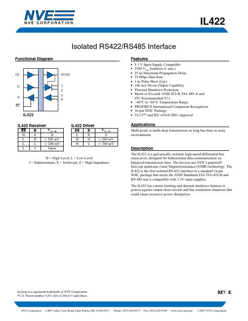
ITU Recommended V11 • −40°C to +85°C Temperature Range • PROFIBUS International Component Recognition • 16-pin SOIC Package • UL1577 and IEC 61010-2001 Approval
Parameters Maximum Data Rate Differential Output Prop Delay Pulse Skew(10) Differential Output Rise & Fall Time Output Enable Time to High Level Output Enable Time to Low Level Output Disable Time from High Level Output Disable Time from Low Level Skew Limit(3)
Model
Package
IL422
0.3" SOIC
Pollution Degree II
UL 1577
Component Recognition Pprogram File Number: E207481 Rated 2500VRMS for 1 minute (SOIC)
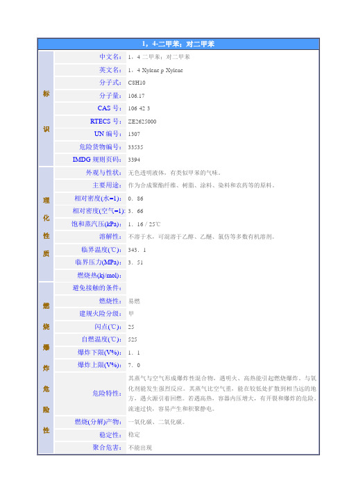
对二甲苯
识
中文名:
1,4-二甲苯;对二甲苯
英文名:
1,4-Xylene p-Xylene
分子式:
C8H10
分子量:
106.17
CAS号:
106-42-3
RTECS号:
ZE2625000
UN编号:
1307
危险货物编号:
33535
IMDG规则页码:
3394
理
化
性
质
外观与性状:
无色透明液体,有类似甲苯的气味。
主要用途:
作为合成聚酯纤维、树脂、涂料、染料和农药等的原料。
相对密度(水=1):
0.86
相对密度(空气=1):
3.66
饱和蒸汽压(kPa):
1.16/25℃
溶解性:
不溶于水,可混溶于乙醇、乙醚、氯仿等多数有机溶剂。
临界温度(℃):
343.1
临界压力(MPa):
3.51
燃烧热(kj/mol):
燃
烧
爆
炸
危
险
性
避免接触的条件:
呼吸系统防护:
空气中浓度超标时,佩带防毒面具。紧急事态抢救或逃生时,建议佩带自给式呼吸器。
眼睛防护:
高浓度蒸气接触可戴化学安全防护眼镜。
防护服:
穿相应的防护服。
手防护:
戴防化学品手套。也可使用皮肤防护膜。
其他:
工作现场禁止吸烟、进食和饮水。工作后,淋浴更衣。保持良好的卫生习惯。
泄漏处置:
疏散泄漏污染区人员至安全区,禁止无关人员进入污染区,切断火源。建议应急处理人员戴好防毒面具,穿一般消防防护服。在确保安全情况下堵漏。喷水雾会减少蒸发,但不能降低泄漏物在受限制空间内的易燃性。用活性炭或其它惰性材料吸收,然后使用无火花工具收集运至废物处理场所处置。也可以用不燃性分散剂制成的乳液刷洗,经稀释的洗水放入废水系统。如大量泄漏,利用围堤收容,然后收集、转移、回收或无害处理后废弃。
IL420中文资料
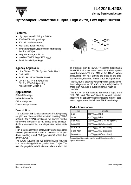
Document Number Optocoupler, Phototriac Output, High dV/dt, Low Input CurrentFeatures•High input sensitivity I FT = 2.0 mA •600/800 V blocking voltage •300 mA on-state current •High static dV/dt 10 kV/µs•Inverse parallel SCRs provide commutating dV/dt > 10 kV/µs•Very low leakage < 10 µA•Isolation Test Voltage 5300 V RMS •Small 6-pin DIP packageAgency Approvals•UL - File No. E52744 System Code H or J •CSA -93751•BABT/ BSI IEC60950 IEC60965 •DIN EN 60747-5-2(VDE0884)DIN EN 60747-5-5 pending Available with Option 1ApplicationsSolid-state relays Industrial controls Office equipmentConsumer appliances.DescriptionThe IL420/ IL4208 consists of a GaAs IRLED optically coupled to a photosensitive non-zero crossing TRIAC network. The TRIAC consists of two inverse parallel connected monolithic SCRs. These three semicon-ductors are assembled in a six pin dual in-line pack-age.High input sensitivity is achieved by using an emitter follower phototransistor and a cascaded SCR pre-driver resulting in an LED trigger current of less than 2.0 mA (DC)The IL420/ IL4208 used two discrete SCRs resulting in a commutating dV/dt of greater than 10 k/µs. The use of a proprietary dV/dt clam results in a static dV/dt of greater than 10 kV/µs. This clamp circuit has a MOSFET that is enhanced when high dV/dt spikes occur between MT1 and MT2 of the TRIAC. When conducting, the FET clamps the base of the pho-totransistors, disabling the firs stage SCR predriver The 600/800 V blocking voltage permits control of off-line voltages up to 240 VAC, with a safety factor of more than two, and is sufficient for as much as 380 VAC.The IL420/ IL4208 isolates low-voltage logic from 120, 240, and 380 VAC lines to control resistive,inductive, or capacitive loads including motors, sole-noids, high current thyristors or TRIAC and relays.Order InformationFor additional information on the available options refer to Option Information.PartRemarksIL420600 V V DRM , DIP-6IL4208800 V V DRM , DIP-6IL420-X006600 V V DRM , DIP-6 400 mil (option 6)IL420-X007600 V V DRM , SMD-6 (option 7)IL420-X009600 V V DRM , SMD-6 (option 9)IL4208-X007800 V V DRM , SMD-6 (option 7)IL4208-X009800 V V DRM , SMD-6 (option 9) Document Number 83629Absolute Maximum RatingsT amb = 25°C, unless otherwise specifiedStresses in excess of the absolute Maximum Ratings can cause permanent damage to the device. Functional operation of the device is not implied at these or any other conditions in excess of those given in the operational sections of this document. Exposure to absolute Maximum Rating for extended periods of the time can adversely affect reliability.InputOutputCoupler1)between emitter and detector, climate per DIN 50014, part 2, Nov. 742) index per DIN IEC 60112/VDE 0303 part 1, group IIIa per DIN VDE 6110ParameterTest conditionSymbol Value Unit Reverse voltage V R 6.0V Forward current I F 60mA Surge current I FSM 2.5A Power dissipation P diss100mW Derate from 25°C1.33mW/°CParameterTest conditionPart Symbol Value Unit Peak off-state voltage IL420V DRM 600V IL4208V DRM 800V RMS on-state current I TM 300mA Single cycle surge current I TSM 3.0A Power dissipation P diss500mW Derate from 25°C6.6mW/°CParameterTest conditionSymbol Value Unit Isolation test voltage 1)t = 1.0 sec.V ISO5300V RMSPollution degree (DIN VDE 0109)2Creepage distance ≥ 7.0mm Clearance≥ 7.0mm Comparative tracking 2)≥ 175Isolation resistanceV IO = 500 V , T amb = 25°C R IO ≥ 1012ΩV IO = 500 V , T amb = 100°CR IO ≥ 1011ΩStorage temperature range T stg - 55 to + 150°C Ambient temperature range T amb- 55 to + 100°C Soldering temperaturemax. ≤ 10 sec. dip soldering ≥ 0.5 mm from case bottomT sld260°CDocument Number Electrical CharacteristicsT amb = 25°C, unless otherwise specifiedMinimum and maximum values are testing requirements. Typical values are characteristics of the device and are the result of engineering evaluation. Typical values are for information only and are not part of the testing requirements.InputOutputCouplerParameterTest conditionSymbol MinTyp.Max Unit Forward voltage I F = 10 mA V F 1.16 1.35V Reverse current V R = 6.0 VI R 0.110µA Input capacitanceV F = 0 V , f = 1.0 MHzC IN 40pF Thermal resistance, junction to ambientR thja750°C/WParameterTest conditionPart Symbol Min Typ.MaxUnit Off-state voltageI D(RMS) = 70 µA IL420V D(RMS)424460V I D(RMS) = 70 µAIL4208V D(RMS) 565V Repetitive peak off-state voltage I DRM = 100 µs IL420V DRM 600V IL4208V DRM 800V Off-state current V D = V DRM,, T A = 100°C I BD 10100µA On-state voltage I T = 300 mAV TM 1.730V On-currentPF = 1.0, V T(RMS) = 1.7 VI TM 300mA Surge (Non-repetitive) on-state current f = 50 Hz I TSM 3.0A Holding current I H65500µA Latching current V T = 2.2 V I L 5.0mALED trigger current V AK = 5.0 VI FT 1.0 2.0Trigger current temperature gradient∆I FT /∆T j7.014µA/°C Critical state of rise off-state voltageV D = 0.67 V DRM , T J = 25°C dV/dt cr 1000V/µs V D = 0.67 V DRM , T J = 80°CdV/dt cr 5000V/µs Critical rate of rise of voltage at current commutation V D = 0.67 V DRM , dI/dt crq ≤ 15 A/ms , T J = 25°CdV/dt crq 10000V/µs V D = 0.67 V DRM ,dI/dt crq ≤ 15 A/ms , T J = 80°C dV/dt crq 5000V/µs Critical state of rise of on-state currentdI/dt cr 8.0A/µs Thermal resistance, junction to ambientR thja150°C/WParameterTest conditionSymbol MinTyp.MaxUnit Critical rate of rise of coupled input/output voltage I T = 0 A, V RM = V DM = V D(RMS)dV/dt 500V/µs Capacitance (input-output) f = 1.0 MHz, V IO = 0 V C IO 0.8pF Isolation resistanceV IO = 500, T A = 25°C R IO 1012ΩV IO = 500, T A = 100°CR IO1011Ω Document Number 83629Switching CharacteristicsTypical Characteristics (T amb = 25 °C unless otherwise specified)ParameterTest conditionSymbol MinT yp.MaxUnit Turn-on timeV RM = V DM = V D(RMS)t on 35µs PF = 1.0, I T = 300 mAt off50µsFig.1Forward Voltage vs. Forward Current Fig.2Peak LED Current vs. Duty Factor, Tau iil420_01100101.10.70.80.91.01.11.21.31.4IF -Forward Current -mAV F -F o r w a r d V o l t a g e -Viil420_02101010101010101010100100010000t -LED Pulse Duration -sI f (p k )-P e a k L E D C u r r e n t -m AFig.3Maximum LED Power DissipationFig.4Typical Output Characteristicsiil420_03100806040200-20-40-60050100150Ta -Ambient Temperature -°CL E D -L E D P o w e r -m Wiil420_04I T =f(V T ),parameter:T jDocument Number Fig.5Current Reduction Fig.6Current Reduction Fig.7Typical Trigger Delay Time iil420_05I TRMS =f(T A ),R thJA =150K/W Device switch soldered in pcb or base plate.iil420_06I TRMS =f(T PIN5),R thJ–PIN5=16.5K/W Thermocouple measurement must be performed potentially separated to A1and A2.Measuring junction as near as possible at the case.Fig.8Typical Off-State CurrentFig.9Power DissipationFig.10Pulse Trigger Currentiil420_09for 40to 60Hz line operation,P tot =f(I TRMS )Package Dimensions in Inches (mm) Document Number 83629Ozone Depleting Substances Policy StatementIt is the policy of Vishay Semiconductor GmbH to1.Meet all present and future national and international statutory requirements.2.Regularly and continuously improve the performance of our products, processes, distribution andoperatingsystems with respect to their impact on the health and safety of our employees and the public, as well as their impact on the environment.It is particular concern to control or eliminate releases of those substances into the atmosphere which are known as ozone depleting substances (ODSs).The Montreal Protocol (1987) and its London Amendments (1990) intend to severely restrict the use of ODSs and forbid their use within the next ten years. Various national and international initiatives are pressing for an earlier ban on these substances.Vishay Semiconductor GmbH has been able to use its policy of continuous improvements to eliminate the use of ODSs listed in the following documents.1.Annex A, B and list of transitional substances of the Montreal Protocol and the London Amendmentsrespectively2.Class I and II ozone depleting substances in the Clean Air Act Amendments of 1990 by the EnvironmentalProtection Agency (EPA) in the USA3.Council Decision 88/540/EEC and 91/690/EEC Annex A, B and C (transitional substances) respectively. Vishay Semiconductor GmbH can certify that our semiconductors are not manufactured with ozone depleting substances and do not contain such substances.We reserve the right to make changes to improve technical designand may do so without further notice.Parameters can vary in different applications. All operating parameters must be validated for each customer application by the customer. Should the buyer use Vishay Semiconductors products for any unintended or unauthorized application, the buyer shall indemnify Vishay Semiconductors against all claims, costs, damages, and expenses, arising out of, directly or indirectly, any claim of personal damage, injury or death associated with such unintended or unauthorized use.Vishay Semiconductor GmbH, P.O.B. 3535, D-74025 Heilbronn, GermanyTelephone: 49 (0)7131 67 2831, Fax number: 49 (0)7131 67 2423Document Number 。
ILE4264中文资料
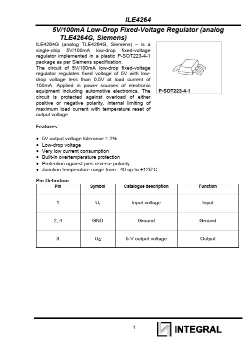
5V/100mA Low-Drop Fixed-Voltage Regulator (analog TLE4264G, Siemens)ILE4264G (analog TLE4264G, Siemens) – is asingle-chip 5V/100mA low-drop fixed-voltageregulator implemented in a plastic P-SOT223-4-1package as per Siemens specification.The circuit of 5V/100mA low-drop fixed-voltageregulator regulates fixed voltage of 5V with low-drop voltage less than 0.5V at load current of100mA. Applied in power sources of electronicequipment including automotive electronics. Thecircuit is protected against overload of eitherpositive or negative polarity, internal limiting ofmaximum load current with temperature reset ofoutput voltageFeatures:•5V output voltage tolerance ± 2%• Low-drop voltage•Very low current consumption•Built-in overtemperature protection•Protection against pins reverse polarity•Junction temperature range from - 40 up to +125°С.Pin DefinitionPin Symbol Catalogue description Function1 U I Input voltage Input2, 4 GND Ground Ground3 U Q5-V output voltage OutputABSOLUTE MAXIMUM RATINGSOperating valuesAbsolutemaximum valuesParameter Unit min max min maxJunction temperature, ТJ OC -40 125 -40 150Storage temperature, Тstg OC - - -50 150 Input voltage, U I V 5,5 45 -42 42 Input current, I I А - Limited internally - NotlimitedinternallyCurrent on “ground” (pin 2),I GND mA 15 - 50 - Output current (pin 3) А - Limited internally - NotlimitedinternallyResistance junction-case, R thJC °С/Wt - 25* - 25*Resistance junction-air, R thJA °С/Wt - 125* - 125* Notes:1 * - R th ja - thermal resistance “junction-air” (for IC without additional external heat sink), ОС/Wt. The same parameter in analog IC is R th ja = 125 ОС/Вт (by “Siemens” information data). Thermal resistance “junction-air” of this circuit is determined in the course of research & development work. For the circuit with additional external heat sink:R th ja = R th jc + R th ca , (1)Where R th jc – IC thermal resistance “junction-case”, ОС/Wt. . The same parameter in analog IC is R th jc = 25 ОС/Wt ((by “Siemens” information data). Thermal resistance “case-air” R th ca in the designed IC is determined by heat sink structure and specified by IC consumer.Heat sink, switching “on” mode (power consumed) and ambient temperature should ensure junction temperature not more than T J ≤ +125 ОС.2 Absolute maximum power P tot ,Wt, dissipated by the IC at the ambient temperature T A , is determined as:P tot = (125 - T A ) / R th ja , (2)where 125 – absolute maximum junction operation temperature, ОСTypical electrical parameters (V I =13,5 V, T J=25°С, unless specified otherwise)Parameter Symbol Test conditions Typ. ValueSupply voltage suppression, dB SVR f = 100 Hz, U R = 0.5U PP, 54Electrical parameters(V I=13.5V, -40 o C ≤ T J≤ 125 o C, unless specified otherwise)Standard ParameterSymbol Test conditionsmin max Output voltage, V U Q6V≤U I≤28V5mA≤I Q≤100mA4.95.1Output current, mA I Q120 Consumption current, mA,I q = I I - I QI q I Q=1 mA 0,4I Q=100 mA 15Drop voltage, V U Dr I Q=100 mA 0.5Output voltage versus load current, mV ∆U Q(I) 5mA≤ I O≤ 100mAV I = 6 V40Output voltage versus input voltage, mV ∆U Q(U) 6V≤ U I≤ 28VI Q=5mA30Notes:1 The electrical parameters are measured when input capacitor C I = 1000 mkF and output capacitor C Q = 10 mkF are connected. Application circuit is in attachment A. IC block diagram is in attachment B.2 The parameters indicated in table 1 are guaranteed at constant junction temperature Tj. The parameters should be measured using pulse equipment.TYPICAL APPLICATION CIRCUIT OF ILE4264GBlock diagram。
SLE4442中文资料
ICs for Chip CardsSLE 4432/42Intelligent 256-Byte EEPROMSLE 4440Intelligent 64-Byte EEPROMSLE 4441Intelligent 128-Byte EEPROMData Sheet 09.98ExtensionSLE 4432/40/41/42 Data Sheet ExtensionRevision History:Original Version 09.98Previous Releases:Page Subjects (changes since last revision)Important:For further information please contact:Siemens Semiconductor Group in Munich, Germany,Security & Chip Card ICs,Fax +49 89 636-22360The supply of this component does not include a license for its use in smartcard applications. This license is due to INNOVATRON Patents137 Boulevard de Sébastopol, 75002 Paris, France, Fax +33 1 4013 3909 Published by Siemens AG, Bereich Halbleiter, HL CC Applications Group Balanstr. 73, D-81541 München© Siemens AG 1998. All Rights Reserved.Attention please!As far as patents or other rights of third parties are concerned, liability is only assumed for components, not for applications, processes and circuits implemented within components or assemblies.The information describes the type of component and shall not be considered as assured characteristics.Terms of delivery and rights to change design reserved.For questions on technology, delivery, and prices please contact the Semiconductor Group Offices in Germany or the Siemens Companies and Representatives world-wide (see address list).Due to technical requirements components may contain dangerous substances. For information on the types in question please contact your nearest Siemens Office, Semiconductor Group.Siemens AG is an approved CECC manufacturer.PackingPlease use the recycling operators known to you. We can also help you – get in touch with your nearest sales office. By agreement we will take packing material back, if it is sorted. You must bear the costs of transport.For packing material that is returned to us unsorted or which we are not obliged to accept, we shall have to invoice you for any costs incurred.Components used in life-support devices or systems must be expressly authorized for such purpose!Critical components1) of the Semiconductor Group of Siemens AG, may only be used in life-support devices or systems2) with the express written approval of the Semiconductor Group of Siemens AG.1) A critical component is a component used in a life-support device or system whose failure can reasonably beexpected to cause the failure of that life-support device or system, or to affect its safety or effectiveness of that device or system.2)Life support devices or systems are intended (a) to be implanted in the human body, or (b) to support and/ormaintain and sustain human life. If they fail, it is reasonable to assume that the health of the user may beSLE 4441Intelligent 256-Byte EEPROM with Write Protect Function SLE 4432Intelligent 256-Byte EEPROM with Write Protect Function SLE 4442and Programmable Security Code (PSC)Features• 256 x 8-bit EEPROM organization • Byte-wise addressing• Irreversible byte-wise protection of lowest 32 addresses(Byte 0...31)• 32 x 1-bit organization of protection memory • Two-wire link protocol• End of processing indicated at data output • Ambient temperature T A -35... +80°C • Supply voltage 5 V −5 / +10 %• Supply current < 10 mA• EEPROM programming time 5 ms• ESD protection typical 4000 V• Endurance minimum 105 write/erase cycles / bit 1)•Data retention for minimum of 10 years 1)•Contact configuration and Answer-to-Reset (synchronous transmission) in accordanceto ISO standard 7816A dditional Feature of SLE 4442• Data can only be changed after entry of the correct 3-byte programmable security codeT ypeO rdering Code P ackageS LE 4432 M3o n request W ire-Bonded Module M3S LE 4432 Co n requestChipS LE 4442 M3o n request W ire-Bonded Module M3S LE 4442 Co n requestC hipSLE 4441I ntelligent 64-Byte EEPROM with Write Protect Function SLE 4440and Programmable Security Code (PSC)I ntelligent 128-Byte EEPROM with Write Protect Function SLE 4441and Programmable Security Code (PSC)• 64 x 8-bit EEPROM organization (SLE 4440)• 128 x 8-bit EEPROM organization (SLE 4441)• Byte-wise addressing• Irreversible byte-wise protection of lowest 32 addresses(Byte 0...31)• 32 x 1-bit organization of protection memory • Two-wire link protocol• End of processing indicated at data output • Ambient temperature T A -35... +80°C • Supply voltage 5 V −5 / +10 %• Supply current < 10 mA• EEPROM programming time 5 ms• ESD protection typical 4000 V• Endurance minimum 105 write/erase cycles / bit 1)• Data retention for minimum of 10 years 1)• Contact configuration and Answer-to-Reset (synchronous transmission) in accordance to ISO standard 7816• Data can only be changed after entry of the correct 3-byte programmable security codeT ype O rdering Code P ackageS LE 4440 M3o n request W ire-Bonded Module M3S LE 4440 Co n requestC hipS LE 4441 M3o n request W ire-Bonded Module M3S LE 4441 Co n requestC hipSLE 4441I ntroductionT his document describes changes and extensions of the Data Sheet 07.95 of SLE 4432 / SLE 4442. All information of the Data Sheet 07.95 are also valid for SLE 4440 and SLE 4441 (e.g. operational information) except the data mentioned in this document.I n detail the following items are added or changed•Memory size SLE 4440•Memory size SLE 4441•Ambient temperature T A –35°C…+80°C•ESD protection min. 1500 V, typical 4000 V•Endurance minimum 100000write/erase cycles / bit•Package: Module M3•Coding informationE specially the transmission protocol (2-wire) and commands are fully compatible for all chip types.1.Memory OverviewT he memory is organized in a Main Memory of•64 byte for SLE 4440•128 byte for SLE 4441•256 byte for SLE 4432 and SLE 4442E ach of the first 32 bytes of the Main Memory can be irreversibly protected against data change by writing the corresponding bit in the Protection Memory (32 bit). Dependent on the state of the protection bit the memory is read only (ROM) or may be erased and written again (EEPROM). Change of the manufacturer code is only possible by the chip manufacturer.C hange of data of the Main Memory and write a bit of the Protection Memory is only possible after a correct verification of the P rogrammable S ecurity C ode (PSC) for SLE 4440, SLE 4441 and SLE 4442.SLE 4441F igure 1Memory Overview SLE 4432SLE 4441F igure 3Memory Overview SLE 4440SLE 44412.CodingS LE 4432, SLE 4442, SLE 4440 and SLE 4441 are delivered with a customer related unique code in order to allow an unambiguous identification of the application. Thus a terminal can clearly accept or reject a card after reading the Answer-to-Reset and the identification data. The Answer-to-Reset (ATR) for synchronous IC cards according to ISO/IEC 7816 is a standardized procedure allowing to identify an IC card (ICC) supporting the synchronous Answer-to-Reset. The Answer-to-Reset data allow an interface device to select the appropriate chip type and operate the ICC according to the data sheet of the chip.T wo different coding schemes apply•Extended coding using encoded BER-TLV data objects according to ISO/IEC 7816-4•16-bit manufacturer code registered at Pro ElectronB oth schemes identify the application by the registered application provider identifier RID according to ISO/IEC 7816-52.1.Registered Application Provider Identifier RIDT he application is generally identified by the customer specific 5-byte registered application provider identifier RID according to ISO/IEC 7816-5 using the registration category values ‘A’ and ‘D’. The RID is a part of the AID. Thus the AID is constructed as following:A pplication identifier AIDR egistered application provider identifierRID (5 byte)P roprietary application provider identifier extension PIX (≤11 byte)•Registered application provider identifier RIDCustomer specific RID provided by the registration authority to the applicantR ID M eaning C omment‘A x xx xx xx xx’I nternational registration R ID is registered by Tele Denmark‘D c cc xx xx xx’N ational registration R ID is registered by a national authority ‘c cc’C ountry indicator C ountry code according to ISO 3166‘xx xx xx’A pplication provider sequence no.P rovided by national registration authority•Proprietary application provider identifier extension PIXExtension for the RID holder in order to diversify own applicationsA pplication forms for a RID are printed in the Annex A of ISO/IEC 7816-5.•For international registration one has to apply at the acting registration authority Tele Denmark for a RID indicated by ‘A’. The contact address is printed in ISO/IEC 7816-5•For national registration one has to apply at the relevant national standardization body or its acting registration authority for a RID indicated by ‘D’ followed by the country codeT he RID is provided by the customer to Siemens.SLE 44412.2.Extended Coding SchemeD ue to the available memory space the coding principle according to ISO/IEC 7816-4 applies for SLE 4432, SLE 4442, SLE 4440 and SLE 4441. Data are coded according to the ASN 1 data objects basic encoding rules using the structure Tag - Length - Value (BER TLV).F igure 5Structure of a Mono- Application Memory IC Card with a simple DIR-StructureT wo coding principles apply•Extended Coding Scheme (Compressed)H1H2H3H4T M L M I CM I CT T A L A R ID P IX•Extended Coding Scheme (according to German Health Insurance)H1H2H3H4T M L M I CM I CT…T T L T T A L A R ID P IXT he byte definition is explained in the following:A TR headerB yte H1:Protocol type = ‘A2’ indicating two-wire link protocolB yte H2:Protocol parameterB yte H3:Historical byte “Category Indicator” = ‘10’ indicating that the following byte H4 will be aDIR data referenceB yte H4:Historical byte “DIR data reference” = a pointer (byte address) to the first byte of thedirectory section (i.e. TA for Extended Coding Scheme - Compressed or TT forExtended Coding Scheme - according to German Health Insurance)SLE 4441A TR data sectionB yte TM:Tag manufacturing data object (‘pre-issuing data’) = ‘46’B yte LM:Length of manufacturing dataB yte ICM:IC manufacturer = ‘05’. For existing applications ICM = ’81’ is still availableB yte ICT:IC TypeD IR data sectionT he DIR data section contains according to ISO/IEC 7816-5 data objects for application selection. The following variants are possible:•The IC card is a mono application card and only the data object ‘application identifier’ (tag TA = ‘4F’) is present in the DIR data section. È Extended Coding Scheme (Compressed)•The IC card is a mono application card with the data object ‘application template’ (tag TT = ‘61’) in the DIR data section. The application template can contain along with the application identifier (tag TA = ‘4F’) further data objects (e.g. application label - tag ‘50’ or discretionary data - tag ’53’). È Extended Coding Scheme (according to German Health Insurance)N ote: Bytes H1, H2, H3, H4, ICM, ICT and the customer specific RID are programmed by Siemens and protected against further changes.2.3.16-bit Coding SchemeF or applications requiring only a unique coding the following construction applies2 byte1 byte5 byteM anufacturer Code M anufac-turer data R egistered application provideridentifier RID•Manufacturer Code registered at Pro Electron16-bit code provided by Siemens, fix for SLE 4432, SLE 4442, SLE 4440 and SLE 4441• Manufacturer dataDifferentiation of chip types SLE 4432, SLE 4442, SLE 4440 and SLE 4441•Registered application provider identifier RIDCustomer specific RID provided by the registration authority to the applicantNote: The above mentioned 8 bytes are programmed by Siemens and protected against further changes.SLE 44412.4.Codes OverviewSLE 4432, SLE 4442, SLE 4440 and SLE 4441 are available with the coding schemes.Please note that according to ISO/IEC 7816-6 Amendment 1 ICM = ‘05’ for new implementations. For existing applications ICM =’81’ is still available. It is recommended that terminals accept both IC manufacturer codes.Address012345678910…1415(dec)Address0123456789A…E F(hex)Meaning H1H2H3H4TM LM ICM ICT TA LA RID PIXData A2131088460205054F RID SLE 4432Data A2131088460205154F RID SLE 4442Data A2031088460205174F RID SLE 4440Data A20B1088460205164F RID SLE 4441 Figure 6Extended Coding Scheme (compressed)Address01234567…1718192021…2526(dec) Address01234567…1112131415…191A(hex) Meaning H1H2H3H4TM LM ICM ICT TT LT TA LA RID PIXData A21310910505RID SLE 4432 Data A21310910515RID SLE 4442 Data A20310910517RID SLE 4440 Data A20B10910516RID SLE 4441Figure 7Extended Coding Scheme (according to German Health Insurance)Address0123 (7)Meaning Manufacturer Code Manufac-turer data Registered application provideridentifier RIDData317401RID SLE 4432 Data317402RID SLE 4442 Data317404RID SLE 4440 Data317408RID SLE 4441Figure 816-bit Coding SchemeThe shaded bytes are programmed by Siemens and protected against further changes.SLE 4441 3.Operational Information3.1.Memory Map SLE 4440Main Memory Protection Memory Security MemoryAddress(decimal)64Data Byte 64 (D7 0::32Data Byte 32 (D7 031Data Byte 31 (D7...D0)Protection Bit 31 (D31):::4Data Byte 4 (D7...D0)Protection Bit 4 (D31)3Data Byte 3 (D7...D0)Protection Bit 3 (D3)Reference Data Byte 3 (D7 02Data Byte 2 (D7...D0)Protection Bit 2 (D2)Reference Data Byte 2 (D7 01Data Byte 1 (D7...D0)Protection Bit 1 (D1)Reference Data Byte 1 (D7 00Data Byte 0 (D7...D0)Protection Bit 0 (D0)Error CounterThe Data bytes 0 to 31 can be protected against further changes by programming the associated protection bit 0 to 31. The SLE 4440 allows data changing only after correct verification of the Reference Data bytes. Reading of the Data bytes and of the associated protection bits is always possible.3.2.Memory Map SLE 4441Main Memory Protection Memory Security MemoryAddress(decimal)128Data Byte 128 (D7 0::32Data Byte 32 (D7 031Data Byte 31 (D7...D0)Protection Bit 31 (D31):::4Data Byte 4 (D7...D0)Protection Bit 4 (D31)3Data Byte 3 (D7...D0)Protection Bit 3 (D3)Reference Data Byte 3 (D7 02Data Byte 2 (D7...D0)Protection Bit 2 (D2)Reference Data Byte 2 (D7 01Data Byte 1 (D7...D0)Protection Bit 1 (D1)Reference Data Byte 1 (D7 00Data Byte 0 (D7...D0)Protection Bit 0 (D0)Error CounterThe Data bytes 0 to 31 can be protected against further changes by programming the associated protection bit 0 to 31. The SLE 4441 allows data changing only after correct verification of the Reference Data bytes. Reading of the Data bytes and of the associated protection bits is always possible.SLE 44414.Electrical CharacteristicsThe listed characteristics are ensured over the operating range of the integrated circuit. Typical characteristics specify mean values expected over the production spread. If not otherwise specified, typical characteristics apply at T A = 25°C and the give supply voltage.4.1.Absolute Maximum RatingsStresses above those listed may cause permanent damage to the device. This is a stress rating only and functional operation of the device at these or any other conditions above those indicated in the operational sections of this data sheet is not implied. Exposure to absolute maximum rating conditions for extended periods may effect device reliability, including EEPROM data retention and write/erase endurance.Parameter Symbol Limit Values Unit Test Conditionmin.typ.max.ESD protection V S1*******V ISO/IEC 7816-1 Endurance 1)105—(write/erase cycles/bit)Data retention 1)10years—1)Values are temperature dependent, for further information please refer to your Siemens SalesOffice.4.2.Operation RangeParameter Symbol Limit Values Unit Test Conditionmin.typ.max.Ambient temperature T A-35+80°C—SLE 4441 5.PackageFigure 9Package Outlines Wire-Bonded Module M3。
ICS426中文资料
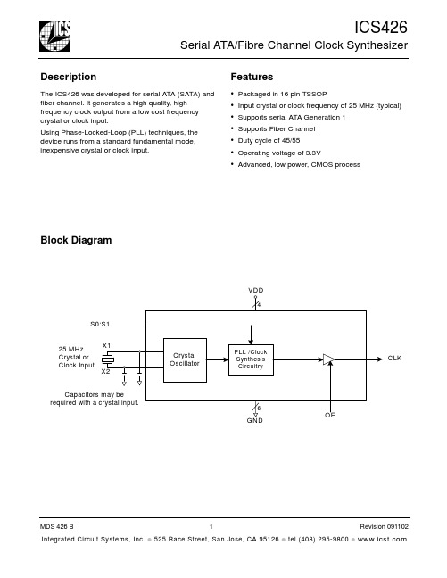
Pin Assignment
X1/ICLK VDD VDD GND GND S1 VDD CLK 1 2 3 4 5 6 7 8 16 15 14 13 12 11 10 9 X2 GND GND OE GND S0 VDD GND
Crystal Load Capacitors
The device crystal connections should include pads for small capacitors from X1 to ground and from X2 to ground. These capacitors are used to adjust the stray capacitance of the board to match the nominally required crystal load capacitance. Because load capacitance can only be increased in this trimming process, it is important to keep stray capacitance to a minimum by using very short PCB traces (and no vias) between the crystal and device. Crystal capacitors, if needed, must be connected from each of the pins X1 and X2 to ground.
6
GND
OE
MDS 426 B Integrated Circuit Systems, Inc.
TLE4264中文资料
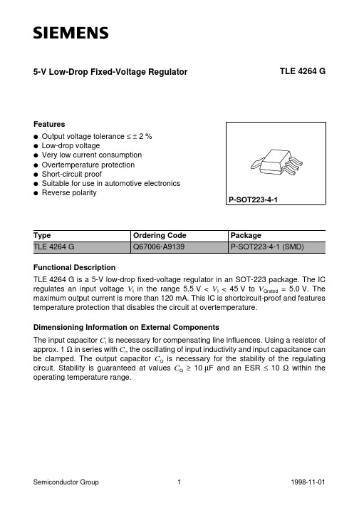
TLE 4264 G
Input 5.5 to 45 V
Ci
1
3
TLE 4264G
2,4
Output 10 µF
AES01528
Application Circuit
Semiconductor Group
6
1998-11-01
TLE 4264 G
Drop Voltage VDr versus Output Current IQ
Vr = 0.5 Vpp
1) Drop voltage = VI – VQ (measured where VQ has dropped 100 mV from the nominal value obtained at VI = 13.5 V)
Semiconductor Group
5
1998-11-01
5.00
AED01982
4.90
4.80
4.70
Output Current IQ versus Input Voltage Vi
200 Ι Q mA
AED01983
150 Tj = 25 C
100 Tj80 120 C 160 Tj
Output Voltage VQ versus Input Voltage Vi
min. max.
Input
Input voltage Input current
VI
– 42 45
V
II
–
–
–
Output
Output voltage Output current
VQ
–1
16
V
IQ
–
–
–
BTS442E2中文资料
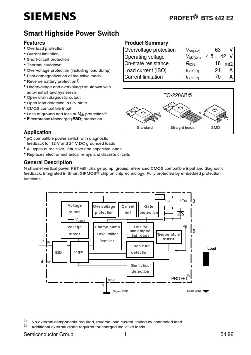
Semiconductor Group
3
元器件交易网
BTS 442 E2
Parameter and Conditions
at Tj = 25 °C, Vbb = 12 V unless otherwise specified
Vbb(over) Vbb(o rst) ∆Vbb(over) Vbb(AZ) Ibb(off) IL(off) IGND
5) 6) 7)
At supply voltage increase up to Vbb= 6.5 V typ without charge pump, VOUT ≈Vbb - 2 V see also VON(CL) in table of protection functions and circuit diagram page 7. Meassured without load. Add IST, if IST > 0, add IIN, if VIN>5.5 V
Semiconductor Group
2
元器件交易网
BTS 442 E2 Electrical Characteristics
Parameter and Conditions
at Tj = 25 °C, Vbb = 12 V unless otherwise specified
元器件交易网
PROFET® BTS 442 E2
Smart Highside Power Switch
Features
• Overload protection • Current limitation • Short-circuit protection • Thermal shutdown • Overvoltage protection (including load dump) • Fast demagnetization of inductive loads • Reverse battery protection1) • Undervoltage and overvoltage shutdown with auto-restart and hysteresis • Open drain diagnostic output • Open load detection in ON-state • CMOS compatible input • Loss of ground and loss of Vbb protection2) • Electrostatic discharge (ESD) protection
Agilent 4294A精确阻抗分析操作手册
安全总结 (7)1、安装 (9)1.1设置和替换保险丝 (9)1。
2电源要求 (9)1。
3电缆线 (9)1.4连接BNC适配器(仅选项1D5) (9)1.5使用局域网(LAN)端口 (9)1。
6连接提供的键盘 (9)1。
7使用支架式装配工具 (9)1.8环境要求 (9)1.9安装地点提供空旷地来散热 (9)1。
10清洁指南 (9)2、学习操作基础 (11)2。
1必需的仪器 (11)2.2测量的准备 (11)2.2.1连接 Agilent 16047 E 测试夹具 (11)2。
2。
2打开电源 (11)2.2。
3将适配器类型设定为“None” (12)2。
3叙述测量条件 (12)2。
3。
1初始化 Agilent 4294 A 到初始状态 (12)2。
3.2选择|Z|-θ作为测量叁数 (12)2。
3.3扫描参数选择频率 (12)2。
3。
4选择对数的扫描作为扫描类型 (12)2。
3。
5设置扫描开始频率为100HZ (12)2.3。
6设置扫描结束频率为100MHZ (13)2。
3。
7设定测量带宽值为 2 (13)2。
4夹具补偿 (13)2.4.1开路状态的夹具补偿 (13)2.4。
2短路状态的夹具补偿 (13)2。
5实行测量并且观察结果 (14)2.5。
1连接 DUT (14)2。
5。
2给纵轴|Z|应用对数的格式 (14)2.5.3给纵轴θ应用线性格式 (15)2。
5.4平行显示|Z|和θ的图 (15)2.5。
5设置|Z|迹为自动调整刻度 (16)2。
5.6设置θ迹为自动调整刻度 (16)2.6结果分析 (16)2.6。
1确定Self—resonance Frequency 和Resonant Impedance (16)3、前/后面板、LCD显示屏 (17)3.1前面板 (17)3。
1。
1Hardkeys (18)1。
设置当前激活的通道的键区 (18)2. 测量功能的键区 (18)3. 与激励有关的键区 (19)4. 数字输入键区 (19)5. 关于定位记号功能的键区 (19)6. 关于仪器状态的键区 (20)7。
NCV4264中文资料
40
50
CURRENT CONSUMPTION (mA)
Figure 6. Current Consumption vs. Input Voltage
450 400 350 300 250 200 150 100
50 0 0
125°C
25°C −40°C
5.0
10
15
20
OUTPUT LOAD (mA)
Features
• 5.0 V Fixed Output • "2.0% Output Accuracy, Over Full Temperature Range • Quiescent Current 400 mA at IOUT = 1.0 mA • 500 mV Maximum Dropout Voltage at 100 mA Load Current • Wide Input Voltage Operating Range of 5.5 V to 45 V • Internal Fault Protection
NCV4264
150 mA Low Dropout Linear Regulator
The NCV4264 is a wide input range, precision fixed output, low dropout integrated voltage regulator with a full load current rating of 150 mA.
5.0
+30
5.0
+40
275 500
83
400
1.5
15
67
−
− 9.0
Unit V
mV
ILQ2中文资料

FEATURES•Current Transfer Ratio at I F =10 mA ILD/Q1, 20% Min.ILD/Q2, 100% Min.ILD/Q5, 50% Min.•High Collector-Emitter Voltage ILD/Q1: BV CEO =50 VILD/Q2, ILD/Q5: BV CEO =70 V•Field-Effect Stable by TRansparent IOn Shield (TRIOS) Isolation Test Voltage, 5300 VAC RMS• Underwriters Lab File #E52744• VDE 0884 Available with Option 1Maximum Ratings (Each Channel)EmitterReverse Voltage ................................................6 V Forward Current ...........................................60 mA Surge Current................................................. 2.5 A Power Dissipation.......................................100 mW Derate Linearly from 25 ° C..................... 1.3 mW/ ° C DetectorCollector-Emitter Reverse VoltageILD/Q1........................................................... 50 V ILD/Q2, ILD/Q5...............................................70 V Collector Current.......................................... 50 mA Collector Current (t<1 ms)...........................400 mA Power Dissipation.......................................200 mW Derate Linearly from 25 ° C......................2.6 mW/ ° C PackageIsolation Test Voltage (between emitter and detector referred to standard climate 23 ° C/50%RH,DIN 50014)....................................5300 VAC RMS Creepage...............................................min. 7 mm Clearance...............................................min. 7 mm Isolation ResistanceV IO =500 V , T A =25 ° C .........................R IO =10 12 Ω V IO =500 V , T A =100 ° C .......................R IO =10 11 Ω Package Power Dissipation ...................... 250 mW Derate Linearly from 25 ° C..................... 3.3 mW/ ° C Storage Temperature................... –40 ° C to +150 ° C Operating Temperature................–40 ° C to +100 ° C Junction Temperature....................................100 ° C Soldering Temperature(2 mm from case bottom)..........................260 ° CV D E DESCRIPTIONThe ILD/Q1/2/5 are optically coupled isolated pairs employing GaAs infrared LEDs and silicon NPN phototransistor. Signal information, including a DC level, can be transmitted by the drive while maintaining a high degree of electrical isolation between input and output. The ILD/Q1/2/5 are especially designed for driving medium-speed logic and can be used to eliminate trou-blesome ground loop and noise problems. Also these couplers can be used to replace relays and transformers in many digital interface applica-tions such as CRT modulation. The ILD1/2/5 has two isolated channels in a single DIP package and the ILQ1/2/5 has four isolated channels per pack-age.See Appnote 45, “How to Use Optocoupler Normalized Curves.”Dimensions in inches (mm).268 (6.81).255 (6.48).790 (20.07).779 (19.77 ).045 (1.14).030 (.76).100 (2.54) Typ.3°–9°.305 Typ. (7.75) Typ..022 (.56).018 (.46).012 (.30).008 (.20).135 (3.43).115 (2.92)Pin One I.D.Pin One I.D..150 (3.81).130 (3.30).040 (1.02).030 (.76 ).268 (6.81).255 (6.48)3465.390 (9.91).379 (9.63).045 (1.14).030 (.76)4° Typ.4° Typ..100 (2.54) Typ.10° Typ.10° Typ.3°–9°.305 Typ.(7.75) Typ..022 (.56).018 (.46).012 (.30).008 (.20).135 (3.43).115 (2.92)1287.150 (3.81).130 (3.30).040 (1.02).030 (.76 )12348765Emitter Collector Collector EmitterAnode Cathode Cathode Anode 16151413121110 912345678Emitter Collector Collector Emitter Emitter Collector Collector EmitterAnode Cathode Cathode Anode Anode Cathode Cathode Anode Quad ChannelDual ChannelDUAL CHANNEL ILD1/2/5 QUAD CHANNEL ILQ1/2/5PHOTOTRANSISTOROPTOCOUPLER元器件交易网元器件交易网CharacteristicsSymbol Min.Typ.Max.Unit ConditionEmitterForward Voltage V F 1.25 1.65V I F=60 mAReverse Current I R0.0110µA V R=6 VCapacitance C025pF V R=0 V, f=1 MHzThermal Resistance, Junction to Lead R THJL750°C/WDetectorCapacitance C CE 6.8pF V CE=5 V, f=1 MHzLeakage Current, Collector-Emitter I CEO550nA V CE=10 VSaturation Voltage, Collector-Emitter V CESAT0.250.4I CE=1 mA, I B=20 µADC Forward Current Gain HFE2006501800V CE= 10 V, I B=20 µASaturated DC Forward Current Gain HFE SAT120400600V CE= 0.4 V, I B=20 µAThermal Resistance, Junction to Lead R THJL500°C/WPackage Transfer Characteristics (Each Channel)Symbol Min.Typ.Max.Unit Condition ILD/Q1Saturated Current Transfer Ratio (Collector-Emitter)CTR CESAT75%I F=10 mA, V CE=0.4 VCurrent Transfer Ratio (Collector-Emitter)CTR CE2090300%I F=10 mA, V CE=10 VILD/Q2Saturated Current Transfer Ratio (Collector-Emitter)CTR CESAT170%I F=10 mA, V CE=0.4 VCurrent Transfer Ratio (Collector-Emitter)CTR CE100200500%I F=10 mA, V CE=10 VILD/Q5Saturated Current Transfer Ratio (Collector-Emitter)CTR CESAT100%I F=10 mA, V CE=0.4 VCurrent Transfer Ratio (Collector-Emitter)CTR CE50130400%I F=10 mA, V CE =10 VIsolation and InsulationCommon Mode Rejection, Output High C MH5000V/µs V CM=50 V P-P, R L=1 kΩ, I F=0 mA Common Mode Rejection, Output Low C ML5000V/µs V CM=50 V P-P, R L=1 kΩ, I F=10 mA Common Mode Coupling Capacitance C CM0.01pFPackage Capacitance C IO0.8pF V IO=0 V, f=1 MHzTypical Switching TimesFigure 1. Non-saturated switching timingFigure 2. Non-saturated switching timingFigure 3. Saturated switching timingFigure 4. Saturated switching timingV O V CC =5 VR L =75 ΩF=10 KHz,DF=50%I F =10 mA I FV Ot Dt R50%PHL t PLHt St Ft V OV CC =5 V R L F=10 KHz,DF=50%I F =10 mAI FV Ot Dt RV TH =1.5 Vt PHLt PLHt St FFigure 5. Normalized non-saturated and saturated CTR at T A =25 ° C versus LED currentFigure 6. Normalized non-saturated and saturated CTR at T A =25 ° C versus LED currentCharacteristic ILD/Q1I F =20 mA ILD/Q2I F =5 mA ILD/Q5I F =10 mA Unit ConditionDelay, t D 0.8 1.7 1.7 µ s V CE =5 V R L =75 k Ω 50% of V PPRise time, t R 1.9 2.6 2.6 µ s Storage, t S 0.20.40.4 µ s Fall Time, t F1.42.2 2.2 µ s Propagation H-L, t PHL 0.7 1.2 1.1 µs Propagation L-H, t PLH1.42.32.5µsCharacteristicILD/Q1I F =20 mA ILD/Q2I F =5 mA ILD/Q5I F =10 mA Unit ConditionDelay, t D 0.81 1.7µs V CE =0.4 V R L =1 k ΩV CC =5 V V TH =1.5 VRise time, t R 1.227µs Storage, t S 7.4 5.4 4.6µs Fall Time, t F7.613.520µs Propagation H-L, t PHL 1.6 5.4 2.6µs Propagation L-H, t PLH8.67.47.2µs.11101000.70.80.91.01.11.21.31.4If - Forward Current - mAV f -F o r w a r d V o l t a g e - VTa = -55°CTa = 25°CTa = 100°C.11101000.00.51.01.5NCTR(SAT)NCTRIF - LED Current - mAC T R N F - N o r m a l i z e d C T R F a c t o rNormalized to:Vce = 10V, IF = 10mA Ta = 25°CCTRce(sat) Vce = 0.4V元器件交易网Figure 10. Collector-emitter current versus tempera-ture and LED currentFigure 11. Collector-emitter leakage current versus temperatureFigure 12. Propagation delay versus collector load resistor60504030201000510152025303550°C70°C85°CIF - LED Current - mAI c e - C o l l e c t o r C u r r e n t - m A25°C10080604020-2010-210-1100101102103104105Ta - Ambient Temperature - °CI c e o - C o l l e c t o r -E m i t t e r - n ATYPICALVce = 10V .11101001101001000 1.01.52.02.5RL - Collector Load Resistor - K Ωt P L H - P r o p a g a t i o n L o w -H i g h - µst P H L - P r o p a g a t i o n H i g h -L o w - µstPLHtPHLTa = 25°C, IF = 10mA Vcc = 5V, Vth = 1.5V Figure 7. Normalized non-saturated and saturated CTR at T A =50°C versus LED currentFigure 8. Normalized non-saturated and saturated CTR at T A =70°C versus LED currentFigure 9. Normalized non-saturated and saturated CTR at T A =85°C versus LED current.11101000.00.51.01.5NCTR(SAT)NCTRIF - LED Current - mAC T R N F - N o r m a l i z e d C T R F a c t o rNormalized to:Vce = 10V, IF = 10mA, Ta = 25°C Ta = 50°CCTRce(sat) Vce = 0.4V.11101000.00.51.01.5NCTR(SAT)NCTRIF - LED Current - mAC T R - N o r m a l i z e d C T R F a c t o rNormalized to:Vce = 10V, IF = 10mA Ta = 25°CTa = 70°CCTRce(sat) Vce = 0.4V100101.10.00.51.01.5NCTR(SAT)NCTRNormalized to:Vce = 10V, IF = 10mA, Ta = 25°C Ta = 85°C CTRce(sat) Vce = 0.4VIF - LED Current - mAN C T R - N o r m a l i z e d C T R元器件交易网。
X4说明书
Impulse X4 系列便携式复合气体检测仪操作说明书!重要提示:!在首次使用仪器以前请认真阅读本手册,您将会掌握仪器正确的使用方法和了解仪器的功能,包括操作,维护,功能设置等内容。
!为了使操作者更安全,请按照手册中的要求,定期对仪器进行标定。
!如果在使用过程中,遇到的故障或问题在本手册中没有提到,请直接联系制造商Zellweger Analytics,或联系当地的代理商/服务商。
!警告和注意:·更换任何元器件都有可能损坏仪器的本质安全结构。
·如果需要使用存储卡,请选用Zellweger Analytics 提供的存储卡(订货号2566-0435),使用其它的存储卡有可能损坏仪器的本质安全结构。
·在允许的储存期之后激活检测器,有可能影响仪器的使用性能和保质期。
·应使用许可的5号干电池,如劲量电池,不要使用质量低下的干电池,以免影响仪器的本质安全性能。
·在更换电池时,应同时更换2节型号相同的新电池。
·在电池欠压提示后,应尽快更换新电池,以免旧电池漏液损坏仪器。
·在低温环境下,电池的寿命会缩短。
·更换电池时,应该在安全环境下进行。
·当更换任何一个传感器的情况下,都需要对仪器进行标定。
·在每天使用以前,应完成仪器的自检过程。
·定期的对仪器用标气进行测试,检查声、光、振动报警是否正常。
·标定时应选用厂家或国家认证合格企业提供的标准气体。
·标定时应在良好通风的环境下进行,以避免污染。
·不要在仪器电量不足的情况下标定。
·不要在富氧的环境下使用本仪器。
·可燃气体传感器的灵敏度会受到高浓度硫化物,卤素化合物,含硅化合物,以及含铅气体或蒸汽的影响,也叫“中毒”,应避免在以上的环境中使用仪器,如果必须使用,则使用完后应对仪器进行检测和标定,以免影响以后的使用。
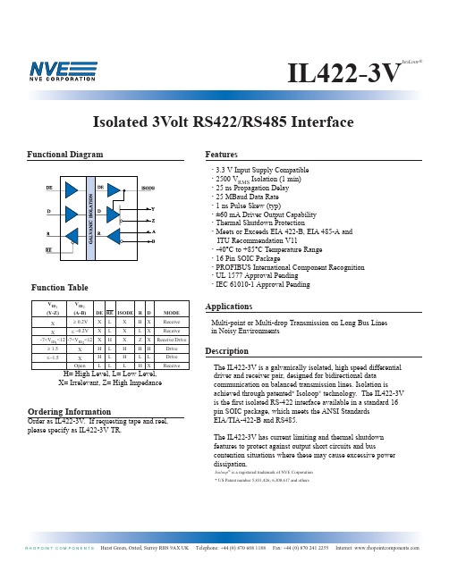
IL422-3V中文资料
Isolated 3Volt RS422/RS485 InterfaceIL422-3VI SO L OOP ®Absolute Maximum RatingsParametersSymbol Min.Max.Units Storage TemperatureT S -65150o CAmbient Operating Temperature T A -4085oCV oltage Range at A or B Bus Pins -712V Supply V oltage (1)V DD 1,V DD 2-0.57V Digital Input V oltage -0.5 5.5V Digital Output V oltage-0.5V DD + 0.1V Continuous Total Power Dissipation 725mW (25°C)377mW (85°C)Maximum Output Current I O95mALead Solder Temperature (10s)260°CESD2kV Human Body ModelInsulation SpecificationsParameterCondition Min.Typ.Max.Units Creepage Distance (External)8.077mm Barrier Impedance >1014 ||7Ω || pF Leakage Current240 V RMS 0.2µA60HzModel Pollution Material Max Working P ackage TypeDegree Group Voltage 16–SOIC (0.3'')IL422II III 400 V RMS9IEC61010-1TUV Certificate Numbers: Pending Classification as Table 1.UL 1577Component Recognition program. File # Pending Rated 2500Vrms for 1min.2IL422-3VI SO L OOP ®Recommended Operating ConditionsParameters Symbol Min.Max.Units Supply V oltageV DD 1 3.0 5.5V V DD 2 4.55.5Input V oltage at any bus terminal V I 12V(separately or common mode)V IC -7High-Level Digital Input V oltage (VDD1=3.3V)V IH 2.4V (VDD1=5.0V)3.0Low-Level Digital Input V oltage V IL 0.8V Differential Input V oltage (2)V ID ±12V High-Level Output Current (Driver)I OH -60mA High-Level Digital Output Current (Receiver)I OH 8mA Low-Level Output Current (Driver)I OL 60mA Low-Level Digital Output Current (Receiver)I OL 8mA Operating Free Air Temperature T A -4085°CDigital Input Signal Rise and Fall Timest IR ,t IFDC StableIL422-3V I SO L OOP®Driver SectionAll Specifications are T min to T max unless otherwise stated.Parameter Symbol Min.Typ.(5)Max.Units Test ConditionsInput Clamp V oltage V IK-1.5V I L=-18mAOutput Voltage V O06V I O=0Differential Output V oltage|V OD1| 1.56V I O=0Differential Output V oltage(6)|V OD2| 1.5 2.55V R L=54ΩDifferential Output V oltage V OD3 1.55V V test=-7 to 12VChange in Magnitude of (7)∆|V OD|±0.2V R L=54or100ΩDifferential Output V oltageCommon Mode Output V oltage V OC3V R L=54or100Ω-1Change in Magnitude of (7)∆|V OC|±0.2V R L=54or100ΩCommon Mode Output V oltageOutput Current(4)I O1mA Output Disabled V O=12-0.8mA V O=-7High Level Input Current I IH10µA V1=3.5 VLow Level Input Current I IL-10µA V1=0.4 VShort-Circuit Output Current I OS-250mA V O= -6-150V O= 0250V O= 8Supply Current (V DD2= +5V)I DD22734(V DD1= +5V)I DD1510mANo Load (Outputs Enabled)(V DD1= +3.3V)I DD1 3.27Switching CharacteristicsParameter Symbol Min.Typ.(5)Max.Units Test ConditionsMaximum Data Rate35Mbd R L=54Ω, C L=50pFDifferential Output Delay Time t D(OD)1625ns R L=54Ω, C L=50pFPulse Skew(10)t SK(P)16ns R L=54Ω, C L=50pFDifferential Output Transition Time t T(OD)810ns R L=54Ω, C L=50pFOutput Enable Time To High Level t PZH3165ns R L=54Ω, C L=50pFOutput Enable Time To Low Level t PZL2235ns R L=54Ω, C L=50pFOutput Disable Time From High Level t PHZ2850ns R L=54Ω, C L=50pFOutput Disable Time From Low Level t PLZ1632ns R L=54Ω, C L=50pFSkew Limit(3)t SK(LIM)28ns R L=54Ω, C L=50pF3Electrostatic Discharge SensitivityThis product has been tested for electrostatic sensitivity to the limits stated in the specifications. However, NVE recommends that all integrated circuits be handled with appropriate care to avoid damage. Damage caused by inappropriate handling or storage could range from performance degradation to complete failure.4IL422-3VI SO L OOP ®Receiver SectionAll Specifications are T min to T max unless otherwise stated.ParameterSymbol Min.Typ.(5)Max.Units Test Conditions Positive-going Input Threshold V oltage V IT +0.2V V O = 2.7V , I o = - 0.4mA Negative-going Input Threshold V oltage V IT -–0.2V V O = 0.5V , I o = 8mAHysteresis V oltage (V IT +- V IT -)V hys 60mV High Level Digital Output V oltage V OH V DD – 0.2V V ID = 200mV , I OH = -20µA Low Level Digital Output V oltage V OL 0.2V V ID = -200mV , I OL = 20µA High-impedance-state output current I OZ ±10µA V O = 0.4 to (V DD 2- 0.5) V Line Input Current (8)I I 1mAOther Input (11) = 0V V I =12V-0.8V I = –7VInput Resistance r I 50k ΩSupply Current(V DD 2= +5V)I DD 22734No Load (Outputs Enabled)(V DD 1= +5V)I DD 1510mA(V DD 1= +3.3V)I DD 1 3.27Switching Characteristics @ 5V ParameterSymbol Min.Typ.(5)Max.Units Test Conditions Maximum Data Rate 25Mbd R L =54Ω, C L =50pF Propagation Time (9)t PD 2432ns V O =-1.5 to 1.5V , C L =15pF Pulse Skew (10)t SK (P )16ns V O =-1.5 to 1.5V , C L =15pFSkew Limit(3)t SK (lim)28ns R L =54Ω, C L =50pFOutput Enable Time To High Level t PZH 1724ns C L =15pF Output Enable Time To Low Level t PZL 3045ns C L =15pF Output Disable Time From High Level t PHZ 3045ns C L =15pF Output Disable Time From Low Level t PLZ1827nsC L =15pFSwitching Characteristics @ 3.3V ParameterSymbol Min.Typ.(5)Max.Units Test Conditions Maximum Data Rate 25Mbd R L =54Ω, C L =50pF Propagation Time (9)t PD 2732ns V O =-1.5 to 1.5V , C L =15pF Pulse Skew(10)t SK (P )26ns V O =-1.5 to 1.5V , C L =15pFSkew Limit (3)t SK (lim)48ns R L =54Ω, C L =50pFOutput Enable Time To High Level t PZH 2024ns C L =15pF Output Enable Time To Low Level t PZL 3345ns C L =15pF Output Disable Time From High Level t PHZ 3345ns C L =15pF Output Disable Time From Low Levelt PLZ2027nsC L =15pFIL422-3V I SO L OOP®5IL422-3V I SO L OOP®Pin Configuration7IL422-3VI SO L OOP ®Recommended profile shown. Maximum temperature allowed on any profile is 260° C.。
SLE4442通信协议
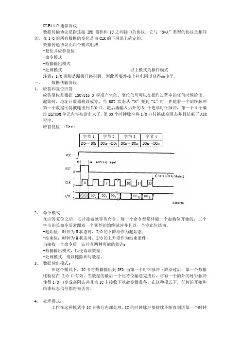
SLE4442通信协议:数据传输协议是指连接IFD器件和IC之间接口的协议。
它与“S=A”类型的协议是相同的。
在I/O的所有数据的变化是由CLK的下降沿上确定的。
数据传递协议由四个模式组成:-复位并应答复位-命令模式-数据输出模式-处理模式以上模式为操作模式注意:I/O引脚是漏极开路引脚,因此需要外接上拉电阻以获得高电平。
一、数据传输协议:1、应答和复位应答应答复位是根据ISO7816-3标准产生的。
复位信号可以在操作过程中的任何时候给出。
起始时,地址计数器被设成零,当RST状态从“H”变到“L”时,伴随着一个始终脉冲第一个数据比特被输出到I/O口。
随后再输入另外的31个连续时钟脉冲,第一个4个编址EEPROM单元内容被读出来了。
第33个时钟脉冲将I/O口转换成高阻态并且结束了ATR 程序。
应答复位:(Hex):字节1字节2字节3字节4DO7…DO0DO15…DO8DO23…DO16DO31…DO242、命令模式在应答复位之后,芯片接着就等待命令。
每一个命令都是伴随一个起始位开始的,三个字节的长命令后紧跟着一个额外的始终脉冲并且以一个停止位结束。
-起始位:时钟为H状态时,I/O的下降沿作为起始态;-结束位:时钟为H状态时,I/O的上升沿作为结束条件。
当接收一个命令后,芯片有两种可能的状态:-数据输出模式,以便读取数据;-处理模式,用以檫除和写数据。
3、数据输出模式:在这个模式下,IC卡将数据输出到IFD.当第一个时钟脉冲下降沿过后,第一个数据比特位在I/O口有效。
当数据的最后一个比特位输送完成后,将有一个额外的时钟脉冲使得I/O口变成高阻态并且为IC卡接收下以命令做准备。
在这种模式下,任何的开始和结束标志信号都将被丢弃。
4、处理模式:工作在这种模式中IC卡执行内部处理。
IC的时钟脉冲要持续不断直到因第一个时钟下降沿而变成L态的I/O口状态变回高阻态。
在此状态下任何形式的开始和结束标志均视为无效。
L426资料
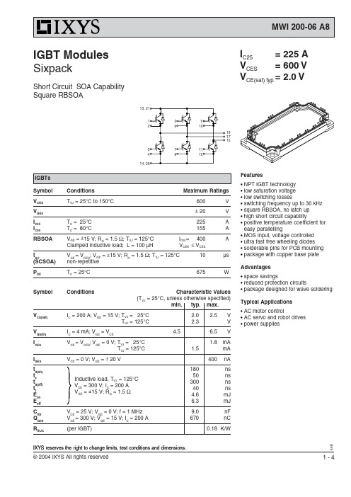
48IXYS reserves the right to change limits, test conditions and dimensions.Features•NPT IGBT technology •low saturation voltage •low switching losses•switching frequency up to 30 kHz •square RBSOA, no latch up •high short circuit capability•positive temperature coefficient for easy parallelling•MOS input, voltage controlled •ultra fast free wheeling diodes •solderable pins for PCB mounting •package with copper base plate Advantages•space savings•reduced protection circuits•package designed for wave soldering Typical Applications •AC motor control•AC servo and robot drives •power suppliesSymbol Conditions Maximum RatingsV CES T VJ = 25°C to 150°C600V V GES ± 20V I C25T C = 25°C 225A I C80T C = 80°C155A RBSOA V GE = ±15 V; R G = 1.5 Ω; T VJ = 125°C I CM = 400A Clamped inductive load; L = 100 µH V CEK ≤ V CESt SCV CE = V CES ; V GE = ±15 V; R G = 1.5 Ω; T VJ = 125°C 10µs (SCSOA)non-repetitive P totT C = 25°C675WSymbol ConditionsCharacteristic Values(T= 25°C, unless otherwise specified)I C25= 225 AV CES= 600 V V CE(sat) typ.= 2.0 VIGBT Modules SixpackShort Circuit SOA CapabilitySquare RBSOA17191548Symbol Conditions Maximum Ratings T VJ operating-40...+125°C T JM +150°C T stg -40...+125°C V ISOL I ISOL ≤ 1 mA; 50/60 Hz 2500V~M dMounting torque (M5) 3 - 6NmSymbol ConditionsCharacteristic Values min.typ.max.R pin-chip 1.8m Ωd S Creepage distance on surface 10mmd A Strike distance in air 10mmR thCH with heatsink compound0.01K/W Weight300gSymbol Conditions Maximum RatingsI F25T C = 25°C 260A I F80T C = 80°C165ASymbol ConditionsCharacteristic ValuesEquivalent Circuits for SimulationConductionIGBT (typ. at V GE = 15 V; T J = 125°C)V 0 = 1.1 V; R 0 = 6 m ΩFree wheeling Diode (typ. at T J = 125°C)V 0 = 1.1 V; R 0 = 2 m ΩThermal ResponseIGBT (typ.)C th1 = 0.397 J/K; R th1 = 0.131 K/W C th2 = 2.243 J/K; R th2 = 0.049 K/W Free wheeling Diode (typ.)C th1 = 0.281 J/K; R th1 = 0.236 K/W C th2 = 1.945 J/K; R th2 = 0.064 K/W48012340123450100150200250300V CEV V CEA V Q G-di/dt67891011120100200300400V V GEA I C0120100200300400500600VV FI F A Fig. 1Typ. output characteristics Fig. 2Typ. output characteristicsFig. 3Typ. transfer characteristics Fig. 4Typ. forward characteristics of free wheeling diodeFig. 5Typ. turn on gate charge Fig. 6Typ. turn off characteristics offree wheeling diode448Fig. 11Reverse biased safe operating area RBSOA Fig. 12Typ. transient thermal impedanceFig. 8Typ. turn off energyversus collector currentFig.10Typ. turn off energyversus gate resistor01002003004004812160.00010.0010.010.11100.0010.010.110481216202468100200300400500600700I CA R GΩV CEts mJ VmJ。
ILE4267G中文资料
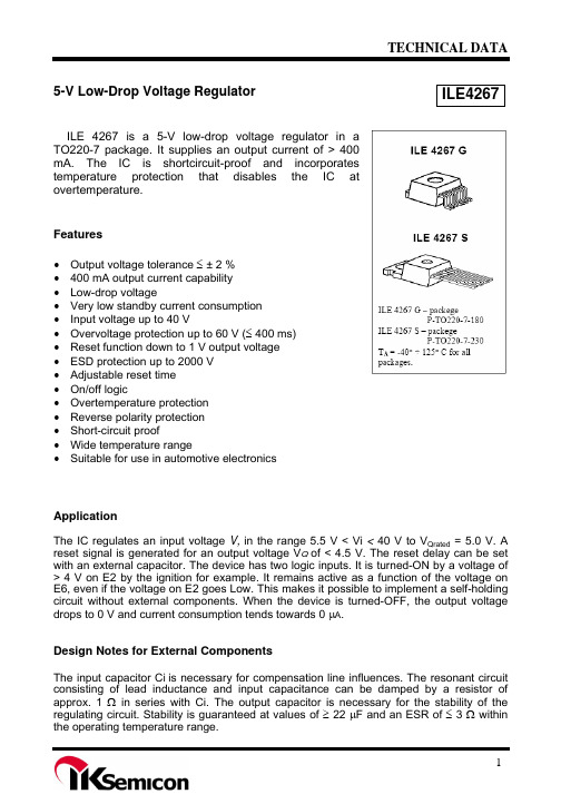
Parameter Output voltage
Symbol
Limit Values min. typ. max.
Features
• Output voltage tolerance ≤ ± 2 % • 400 mA output current capability • Low-drop voltage • Very low standby current consumption • Input voltage up to 40 V • Overvoltage protection up to 60 V (≤ 400 ms) • Reset function down to 1 V output voltage • ESD protection up to 2000 V • Adjustable reset time • On/off logic • Overtemperature protection • Reverse polarity protection • Short-circuit proof • Wide temperature range • Suitable for use in automotive electronics
4
GND Ground; connected to rear of chip
5
D
Reset Delay; connect with capacitor to GND for setting delay
6
E6
Hold; see truth table above for function; this input is connected to output voltage across puliup resistor of 50 kΩ
四正柏生物 小鼠IL-4 ELISA试剂盒说明书

REV20190712仅供研究,不用于临床诊断。
客服热线: 400-7060-959﹡技术支持邮箱: **************公司官网: 目录简介 ........................................................................................................................................................... - 3 -检测原理 ................................................................................................................................................... - 3 -试剂盒组分 ............................................................................................................................................... - 4 -储存条件 ................................................................................................................................................... - 5 -其他实验材料(不提供,但可协助购买) : ............................................................................................. - 5 -注意事项 ................................................................................................................................................... - 5 -样本收集处理及保存方法 ....................................................................................................................... - 6 -试剂准备 ................................................................................................................................................... - 6 -操作步骤 ................................................................................................................................................... - 8 -操作流程图 ............................................................................................................................................... - 8 -操作要点提示 ........................................................................................................................................... - 9 -结果判断 ................................................................................................................................................... - 9 -结果重复性 ............................................................................................................................................. - 10 -灵敏度 ..................................................................................................................................................... - 10 -特异性 ..................................................................................................................................................... - 10 -参考文献 ................................................................................................................................................. - 11 -该产品由北京四正柏生物科技有限公司研制。
4-4'-二羧基联苯砜-安全技术说明书MSDS
第一部分化学品及企业标识化学品中文名:4,4’-二羧基联苯砜化学品英文名:4,4'-Dicarboxydiphenyl Sulfone4,4'-Sulfonyldibenzoic acidCAS No.:2449-35-6分子式:C14H10O6S产品推荐及限制用途:工业及科研用途。
第二部分危险性概述紧急情况概述造成严重眼刺激。
可引起呼吸道刺激。
GHS危险性类别严重眼损伤 / 眼刺激类别 2特异性靶器官毒性一次接触类别 3标签要素:象形图:警示词:警告危险性说明:H319 造成严重眼刺激H335 可引起呼吸道刺激●预防措施:—— P264 作业后彻底清洗。
—— P280 戴防护手套/穿防护服/戴防护眼罩/戴防护面具。
—— P261 避免吸入粉尘/烟/气体/烟雾/蒸气/喷雾。
—— P271 只能在室外或通风良好处使用。
●事故响应:—— P305+P351+P338 如进入眼睛:用水小心冲洗几分钟。
如戴隐形眼镜并可方便地取出,取出隐形眼镜。
继续冲洗。
—— P337+P313 如仍觉眼刺激:求医/就诊。
—— P304+P340 如误吸入:将人转移到空气新鲜处,保持呼吸舒适体位。
—— P312 如感觉不适,呼叫解毒中心/医生●安全储存:—— P403+P233 存放在通风良好的地方。
保持容器密闭。
—— P405 存放处须加锁。
●废弃处置:—— P501 按当地法规处置内装物/容器。
物理和化学危险:无资料。
健康危害:造成严重眼刺激。
可引起呼吸道刺激。
环境危害:无资料。
第三部分成分/组成信息√物质混合物第四部分急救措施急救:吸入:如果吸入,请将患者移到新鲜空气处。
皮肤接触:脱去污染的衣着,用肥皂水和清水彻底冲洗皮肤。
如有不适感,就医。
眼晴接触:分开眼睑,用流动清水或生理盐水冲洗。
如有不适感,就医。
食入:饮水,禁止催吐。
如有不适感,就医。
对保护施救者的忠告:将患者转移到安全的场所。
咨询医生。
出示此化学品安全技术说明书给到现场的医生看。
- 1、下载文档前请自行甄别文档内容的完整性,平台不提供额外的编辑、内容补充、找答案等附加服务。
- 2、"仅部分预览"的文档,不可在线预览部分如存在完整性等问题,可反馈申请退款(可完整预览的文档不适用该条件!)。
- 3、如文档侵犯您的权益,请联系客服反馈,我们会尽快为您处理(人工客服工作时间:9:00-18:30)。
TECHNICAL DATA
ILE4264-2
5-V/100M A L OW P OWER L OW -D ROP F IXED -V OLTAGE R EGULATOR WITH LOW CURRENT CONSUMPTION
ILE 4264-2 P-SOT223-4-1
The ILE 4264-2 is a monolithic integrated Low power low-drop fixed voltage regulator 5-V/100mA with low current consumption. The ILE 4264-2 is specially
designed to create power source with 5V output voltage, loads up to 100 mA and drop voltage less than 0,5V. The regulator is designed to supply electronic device in automotive applications and some another applications. The ILE 4264-2 is equipped with additional protection against overvoltage of both polarities, load current limitation, short-circuit and over temperature shutdown of
output voltage. The IC is supplied in chip (unpackaged) form.
Features
• Output voltage tolerance 5±3% (±2% up to 50 mA) • Low-drop voltage
• Current capability up to150 mA • Very low current consumption • Over temperature protection
• Reverse polarity proof Short-circuit proof • Junction temperature -40 t о +150°С
• Suitable for use in automotive electronics • Short-circuit proof
Block Diagram
Pin description (for P-SOT223-4 package)
Pin Symbol Function 01 I Input voltage; block to ground directly with a ceramic capacitor 03 Q 5-V output voltage; block to ground with a capacitor 02, 04 GND Ground
Typical electric parameters
(U I =13,5 V, -40 o C ≤ T J ≤ 125 o C, unless specified otherwise)
Parameter, unit of measurement Symbol Mode of measurement Typical value
Power Supply Ripple Rejection, dB
PSRR
f r = 100 Hz,
U r = 3 V (peek-to-peek)
68
Absolute Maximum Ratings
Maximum Ratings
Absolute Maximum
Ratings
Parameter, symbol
Unit Min Max Min Max
Junction temperature, ТJ o
C -40* 125 -40* 150 Storage temperature, Тstg o
C - - -50 150 Input voltage, U I V 6 28 -42 45
Input current, I I
mA - Internally limited - Internally
limited
Ground pin current, I GND mA - - 50*** - Output voltage, U Q
V 4,9 5,1 -0,3*** 32*** Output current (pin 3), I Q
mA - Internally limited - Internally
limited
Thermal Resistances
Junction-case , R th jc , for conventional case P-SOT223-4-1
o
C/W - 25** - 25**
Thermal Resistances
Junction-ambient, R th ja , for conventional case P-SOT223-4-1, - without heat sink
o
C/W
-
220** -
220**
* Ambient temperature
** R th ja - Thermal Resistances Junction-ambient *** - Voltage is not applied to pin I
Thermal resistance junction ambient for IC with heat dissipater is calculated by formula:
R th ja = R th jc + R th ca , (1)
Rth jc - thermal resistance junction case, oC /W.
Application circuit and heat dissipater have to provide T J ≤ 125 o С.
Maximum power Ptot,Вт, dissipated by IC for TA , is calculated by formula:
P tot = (125 - T A ) / R th ja , (2)
125 – maximum permitable operating junction temperature, ОС
Electric parameters (U I =13,5 V, -40 o C ≤ T J ≤ 125 o C, unless specified otherwise)
Typical value
Parameter, unit of measurement
Symbol Mode of measurement Min Max
Note
9 V ≤ U I ≤ 16 V 5 mA ≤ I Q ≤ 50 mA 4,9 5,1 Output voltage, V
U Q
6 V ≤ U I ≤ 21 V 5 mA ≤ I Q ≤ 100 mA 4,85 5,15 Maximum output current, mA I Qmax 4,8 V ≤ U Q ≤ 5,2 V 150 500 I Q =0,1 mA, (T J ≤ 85o C)
- 0,06 I Q = 0,1 mA - 0,07 Consumption current, mA, I q = I I - I Q
I q I Q = 50 mA - 4 Drop-out voltage, V U Dr I Q = 100 mA - 0,5 1
Load regulation, mV ΔU Q(I) 1 mA ≤ I Q ≤ 100 mA
U I = 13,5 V - 90 Line regulation, mV
ΔU Q(U)
6 V ≤ U I ≤ 28V I Q = 1 mA
- 30
Notes
1 Drop voltage U Dr = U I - U Q (measured when the output voltage V Q has dropped 100 mV from the nominal value obtained at V I = 13.5 V).
ILE4264-2 Application Circuit
Typical Performance Characteristics
Package Dimensions P-SOT 223-4-1。
