M2安装手册
Oracle Sun Storage 2500-M2 数组安装说明说明书

This document provides an overview of the installation procedure for Oracle’s Sun Storage 2500-M2Arrays,including:■Sun Storage 2540-M2array (controller tray with Fibre Channel host connectivity)■Sun Storage 2530-M2array (controller tray with SAS-2host connectivity)■Sun Storage 2501-M2array (expansion tray)For detailed information,have the Sun Storage 2500-M2Arrays Hardware Installation Guide available as you go through the steps in this document.Additional documentation is listed in the section “Documentation for This Product”and available at the Oracle documentation web site:/technetwork/documentation/oracle-unified-ss-193371.htmlSun Storage Common Array ManagerOracle’s Sun Storage Common Array Manager (CAM)software is a key component for the initial configuration and operation of Sun Storage 2500-M2Arrays hardware.It is installed on a management host cabled to the array via out-of-band Ethernet (cables for this connection are provided).Note :In-band management is also supported.To download and get started with CAM,review the latest Sun Storage Common Array Manager Quick Start Guide .CAM documentation can be found here:/technetwork/documentation/disk-device-194280.htmlNote –It is recommended to begin the download process now so that the software is ready for installation whenhardware installation is complete.Before You BeginReview the following documents before starting the installation:•Important Safety Information for Sun Hardware Systems •Sun Storage 2500-M2Arrays Hardware Release Notes •Sun Storage 2500-M2Arrays Safety and Compliance Manual•Sun Storage 2500-M2Arrays Site Preparation GuideSun Storage 2500-M2 ArraysGetting Started GuideReview Contents of the Ship KitFIGURE 1shows the components of the controller tray ship kit for the Sun Storage 2540-M2array,Sun Storage 2530-M2array,and Sun Storage 2501-M2array expansion tray.Note the following:■AC or DC power cables are included in the ship kit,depending on the configuration ordered.■Small form-factor pluggables (SFPs)are included only with the Sun Storage 2540-M2array.■Cables for connecting the controller tray to the data host (SAS or Fibre Channel)are not included and may be ordered separately.SAS cables for intertray cabling are included with the Sun Storage 2501-M2array expansion tray ship kit.Note :The maximum cable length for 6Gb/sec SAS-2is 10meters.FIGURE 1Controller Tray Ship Kit ContentsInstall the Cabinet and Rail KitBefore installing the rail kit,install and stabilize the cabinet as described in the cabinet installation instructions.Make sure the cabinet’s casters (if any)are locked to prevent the cabinet from rolling,and remove or open the front panel and vented back panel.Then,follow the rail kit installation instructions found in the Installing Adjustable Support Rails document.Note –Each tray requires two standard mounting rack units (2U)of vertical space in the cabinet.Callout Description Callout Description1Documentation6RJ-45-DB9adapter with null modem 2Fibre Channel SFPs (2540-M2only)7Bezel end caps3RJ-45-RJ-45Ethernet cables (one per controller module)8Power cables *-AC cables included for AC configurations -DC cables included for DC configurations *AC power cables shown.4RJ-45-mini-DIN cable 9Controller tray5RJ-45-DB9adapterInstall the Tray in the Cabinet and Connect Power CablesThe following procedure provides an overview of installing a controller tray or expansion tray into the cabinet.Consult the Hardware Installation Guide for further details.Note –Airflow through the tray is front-to-back.For proper ventilation,allow 30in (76cm)clearance in front ofthe cabinet and 24in (61cm)clearance behind the cabinet.Note –When installing tray hardware,load the cabinet so as not to make it top-heavy.One approach is to placethe controller tray in the middle portion of the cabinet while allowing room for expansion trays to be placed above and below the controller tray.FIGURE 2Installing the TrayReview Front PanelFIGURE 3Controller Tray and Expansion Tray Front PanelStep Tasking two people,carefully lift and rest the tray on the bottom ledge of the left and right rails.Caution :Tray equipment can weight up to 60lb (27kg).2.Carefully slide the tray into the cabinet until the front mounting flanges on the tray touch the vertical face of the cabinet and the rear edges of the tray fit into the clips on the support rails.3.Secure the front of the tray by inserting a screw through the center hole in each front mounting flange.(Note :Washers may be required.)Tighten the screws.4.Secure the rear of the tray by inserting a screw through the hole in each rear mounting flange and into each support rail.(Note :Washers may be required.)Tighten the screws.5.Replace the end caps (bezels)that cover the mounting flanges on the front of the array tray.6.Verify that the tray power switches and cabinet circuit breakers are turned off.7.Connect each tray power supply to a separate power source in the cabinet.Callout Description1Left end cap with front panel LEDs 2Disk drives 3Right endcapReview Rear PanelNote:AC power connectors and switches shown.DC configuration is available.See Hardware Installation Guide for more information.FIGURE4Controller Tray Rear ViewFIGURE5Expansion Tray Rear View Callout Description:2540-M2and2530-M2 1Controller module A2Serial port3Ethernet ports4SAS host ports(Not used on2540-M2)5Seven-segment display6Fibre Channel host ports(2540-M2only)7Expansion port8Power-fan module9Controller module LEDs10Power-fan module LEDs11Power connector12Power switch13Controller module BCallout Description:2501-M21Input/output module(IOM)A2IOM LEDs3SAS host ports4Seven-segment display5Serial port6Ethernet port7Expansion port8Power-fan module9Power-fan module LEDs10Power connector11Power switch12IOMBConnect Controller and Expansion TraysFIGURE6shows recommended expansion cabling for one,two,and three expansion trays.See the Hardware Installation Guide for more information.FIGURE6Expansion Tray Cabling ConfigurationsConnect Data HostsFIGURE7shows sample host connection configurations for one host in a direct topology,two hosts in a direct topology,and two hosts in a Fibre Channel switch topology.For Fibre Channel connections(Sun Storage2540-M2only),plug an SFP into a controller host port before cabling.For more information,see the Hardware Installation Guide.Note–The SAS host interface does not support a switch topology.FIGURE7Sample Controller-to-Data Host ConnectionsConnect Management HostConnect an Ethernet cable from the management host port (Ethernet Port 1)of each controller to the LAN of the management host.Note :Ethernet Port 2is reserved for access by Support personnel.Turn on Power and Install Management Host SoftwareTo power on the array,follow the procedure in the Installation Guide .Then,install Sun Storage Common Array Manager on the management host.If you did not previously begin the download process,see the “Sun Storage Common Array Manager”section.During initial array registration,you are prompted to register with the Auto Service Request (ASR)service.It is highly recommended that you register with ASR so that Support can respond appropriately to your needs.Documentation for This ProductAdditional documentation for Sun Storage 2500-M2Arrays is available at:/technetwork/documentation/oracle-unified-ss-193371.htmlOracle Contact InformationReview safety informationSun Storage 2500-M2Arrays Safety and Compliance Manual Important Safety Information for Sun Hardware SystemsReview known issues and workaroundsSun Storage 2500-M2Arrays Hardware Release Notes Sun Storage Common Array Manager Release NotesPrepare the site Sun Storage 2500-M2Arrays Site Preparation Guide Install the arraySun Storage 2500-M2Arrays Hardware Installation Guide Get started with the management software Sun Storage Common Array Manager Quick Start GuideInstall the management software Sun Storage Common Array Manager Installation and Setup Guide Manage the arraySun Storage Common Array Manager Array Administration Guide Sun Storage Common Array Manager CLI GuideDocumentation /technetwork/indexes/documentation/index.html Support https:// Traininghttps://Copyright ©2011,Oracle and/or its affiliates.All rights reserved.Copyright ©2011,Oracle et/ou ses affiliés.Tous droits réservés.Part No.: E20738-01Mfg No.: 7010621June 2011。
霍尼韦尔净水器m2安装教程

霍尼韦尔净水器m2安装教程
霍尼韦尔净水器M2是一种家用净水设备,它可以帮助过滤水中的杂质和污染物,提供安全和清洁的饮用水。
下面是M2净水器的安装教程:
1. 准备工作:
a. 确保你已经购买了霍尼韦尔净水器M2,并检查包装中是否包含所有必要的部件和配件。
b. 确保你已经准备好要安装净水器的位置,并且该位置附近有水源和电源。
2. 安装水龙头接头:
a. 将水龙头接头连接到水龙头上。
确保接头与水龙头紧密连接,并且没有漏水。
3. 安装净水器:
a. 将净水器底部的支架固定在你选择的安装位置上,例如墙壁或柜子侧面。
使用螺丝和螺母来固定支架。
b. 将净水器的主体部分安装在支架上,确保它稳固地固定在支架上。
4. 连接水源:
a. 使用提供的连接管将净水器的进水口连接到水龙头接头上。
确保连接紧密,并没有漏水。
b. 将净水器的出水口连接到你想要获得净水的水龙头或水龙头接口上。
确保连接紧密,并没有漏水。
5. 连接电源:
a. 将净水器的电源插头插入电源插座。
确保净水器的电源线没有破损或受损。
6. 启动净水器:
a. 打开水龙头,让水流经净水器。
这将启动净水器的过滤和净化过程。
b. 等待一段时间,直到净水器完成过滤和净化过程。
此时,你可以关闭水龙头,并开始使用已经过滤和净化的水。
请注意,以上是一般的安装步骤,具体的步骤可能会因净水器型号或其他因素而有所不同。
因此,在安装之前,请务必参考相关的霍尼韦尔净水器M2的安装手册和说明书,以确保正确安装和操作净水器。
睿奥M2安装配置及操作指南

睿奥M2云智能信息化管理平台的安装、配置及常见问题
解决操作指南
一、M2系统的安装
在安装M2软件之前,用户必须要先安装好Microsoft SQL server数据库,下面主要分两部分介绍:
1.1 Microsoft SQL server数据库安装
M2软件支持MS-SQL2000、2005、2008各个版本数据库,如果是XP操作系统,建议安装MS SQL2000,WIN7及以上系统(32位或64位都可以),建议安装MS-SQL2008。
双击下载好的安装文件setup.exe,(注意:安装之前请确认是否有安装SQL Server 2008 R2需要的.NET Framework 3.5 SP1,)弹出sql server安装中心界面,点击左侧栏目“安装”,点击右边栏目的“全新安装或向现有安装添加功能”。
选择输入产品密钥,并输入密钥,并接受许可条款,并点击下一步,选择安装,
选中默认:sql server 功能安装,并点击下一步
功能选择:点击全选按钮,(共享功能目录看个人意愿是否需要修改到其他盘)并点击下一步。
officecorem2使用方法

officecorem2使用方法摘要:1.Office Core M2 简介2.Office Core M2 安装步骤3.Office Core M2 功能介绍4.Office Core M2 实用技巧5.总结与建议正文:随着科技的不断发展,办公软件也在不断更新换代。
今天,我们将为大家介绍一款全新的办公软件——Office Core M2,并详细讲解其使用方法。
希望通过本文,大家能够更好地掌握Office Core M2 的使用技巧,提高工作效率。
1.Office Core M2 简介Office Core M2 是微软公司推出的一款集成办公套件,包括Word、Excel、PowerPoint 等常用办公软件。
相较于之前的Office 版本,Core M2 在界面设计、功能性能等方面都有了很大的提升,更加贴合用户需求。
2.Office Core M2 安装步骤在安装Office Core M2 之前,请确保您的电脑满足系统要求。
具体安装步骤如下:(1)下载Office Core M2 安装包;(2)找到下载好的安装包,双击运行;(3)按照安装向导的提示,完成安装过程。
3.Office Core M2 功能介绍Office Core M2 提供了丰富的功能,帮助用户轻松完成各种办公任务。
以下是部分功能介绍:(1)Word:强大的文字处理软件,支持多种文本格式和排版设置;(2)Excel:专业的电子表格软件,实现数据整理、计算和分析;(3)PowerPoint:便捷的演示文稿制作工具,助力职场汇报和演讲;(4)Outlook:集成邮件、日历、联系人管理等功能的邮件客户端;(5)OneNote:便捷的笔记工具,实现跨平台数据同步。
4.Office Core M2 实用技巧在使用Office Core M2 时,掌握一些实用技巧可以提高办公效率。
以下是一些实用技巧分享:(1)快捷键操作:熟悉并善用快捷键,例如复制、粘贴、格式刷等;(2)模板应用:利用内置模板,快速创建美观专业的文档;(3)云存储:利用OneDrive 等云存储服务,实现文件跨设备同步。
浪潮存储系统AS500N2-M2用户手册 V1.0

M2 用户手册说明书
M2文件编号:RGB-RD-UM-M2C003版本:V1.3用户手册目录目录 (1)声明 (3)声明/担保与赔偿 (3)安全操作概要 (3)安装安全概要 (4)第1章产品简介 (1)1.1随附配件 (1)1.2产品概述 (2)1.2.1后面板 (3)1.2.2前面板 (5)1.2.3外形尺寸图 (11)第2章产品安装 (12)2.1插入信号源 (12)2.2插入电源 (12)2.3设备上电 (12)第3章产品使用 (13)3.1使用菜单键 (13)3.2菜单结构 (14)3.3使用菜单 (15)3.3.1默认菜单 (15)3.3.2主菜单 (15)3.3.3输入 (16)3.3.4输出 (17)3.3.5背景 (18)3.3.6高级 (18)3.3.7Language/语言 (21)3.3.8系统设置 (21)3.3.9出厂复位 (22)3.4PST预编辑 (23)3.4.1信号源选择 (23)3.4.2开关或更换图层 (23)3.4.3冻结图层 (23)3.4.4多画面编辑 (24)3.4.5位置设置 (24)3.4.6缩放及裁剪设置 (25)3.4.7图文叠加设置 (25)3.4.8羽化设置 (27)3.4.9特效图形设置 (28)3.4.10特效模式切换 (30)3.4.11SDI、VGA、CVBS、USB输入画质调节 (31)3.5系统模式 (32)3.5.1普通模式 (32)3.5.24K1K (33)3.5.34K2K (36)3.5.4矩阵模式 (37)3.5.5演示模式 (38)3.6画面切换 (40)3.7背景图片 (42)3.7.1输入信号 (42)3.7.2抓取背景图片 (42)3.7.3从U盘加载图片 (43)3.8输出分辨率设置 (46)3.8.1选择输出分辨率 (46)3.8.2自定义输出分辨率 (46)3.9使用黑场 (48)3.10保存 (49)3.11调保存 (50)第4章订购编码 (51)4.1产品 (51)4.2选配模块 (51)4.2.1输入模块 (51)4.2.2配件 (51)第5章技术支持 (52)5.1联系我们 (52)第6章附录 (53)6.1规格 (53)6.2软件升级 (58)6.3XTOOL的其他使用 (65)6.3.1自定义OSD (65)6.3.2自定义EFFECT转换 (67)6.3.3自定义LOGO (69)6.3.4自定义台标 (71)6.4术语和定义 (74)6.5修订记录 (77)首先感谢您选购我们的产品!为了让您迅速掌握如何使用这款视频处理器,我们为您送上详细的产品使用手册。
M2-200s操作说明
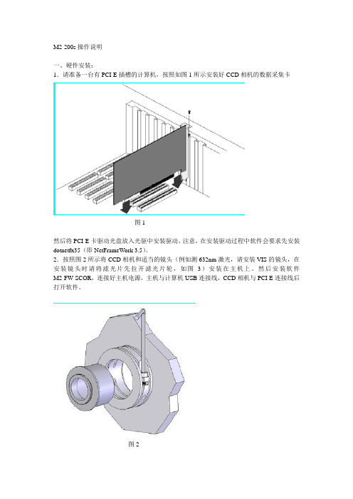
图3
二、软件配置:
软件打开后有如图4所示的菜单选项。“File”菜单主要功能是存储读取文件。“Option”菜单有camera,capture,M2 setup三个选项。其中camera是CCD相机的配置选项,如图5,在camera右边的下拉菜单中选择当前使用相机的序列号,其余不需要修改,但后点击ok完成相机配置;capture选项如图6,可以选择CCD工作模式是连续或者外触发模式,通常选择连续模式,即CW。M2 setup选项如图7,这个选项是测试M2最主要的参数界面,请先输入Wavelength(波长),根据所使用的透镜输入Focal Length,此数值根据使用不同的透镜(UV、VIS、NIR)有不同,如果输入错误将不能正确得到结果,然后输入Z start(开始位置),Z stop(结束位置),和Z Step(步长)的值。Z start最小由仪器本身决定,如果输入过小软件会提示,Z stop则不能超过主机箱体上提示的Z Fixture的值。图7中Capture设置如图8。图7中computations可以选择光斑的计算方法,通常选择4 sgma。“Start!”为开始测试。
图4
图5
图6
图7
图8
三、光路调节:
按照如图9方式摆放光路,并且在图9光路中放置如同10中的合适的衰减片,然后点击软件中如图4中的LIVE按钮,则可以看到软件中的激光光斑,如图11,点击-Z,+Z移动箱体内平移台,可以看到光斑会移动,调整两个反射镜,使光斑在箱体内平移台移动过程中始终在CCD相机的芯片内,即不会移出窗口。如果要想得到最好的测试结果,则需要光斑尽可能只在很小的范围内移动。完成调节后则可以开始测试激光器的M2了。
M2-200s操作说明
一、硬件安装:
X3650M2的Windows系统安装完全手册
X3650M2的Windows系统安装完全手册前言 (1)W INDOWS2003系统在X3650M2的安装方法 (1)X3650M2硬盘里没有数据的情况 (1)X3650M2硬盘里有数据的情况 (2)W INDOWS2008系统在X3650M2的安装方法 (2)X3650M2硬盘里没有数据的情况 (2)X3650M2硬盘里有数据的情况 (3)附录 (3)前言到目前为止,IBM官方对X3650M2只有Windows 2003和Windows 2008兼容性测试,对其它Windows系统没做过兼容性测试,所以本文只适用Widows 2003和Windows 2008,不适用其它Windows系统,对没做过兼容性测试的系统,官方不建议安装。
Windows2003系统在X3650M2的安装方法X3650M2硬盘里没有数据的情况1 准备工作准备Windows 2003 SP2版本的光盘(不要用Windows 2003 标准版和SP1版本的Windows 2003),准备一张最新的Server Guide引导光盘。
(标配不带引导盘,可以去官方网站免费下载,下载地址参考附录)。
2 做阵列(Raid)3650M2通常情况下标配两种Raid卡,Server Raid BR10i卡和Server Raid MR10i卡,对于Server Raid BR10i卡而言,可以不用做阵列。
如果要做的话,开机自检会有Ctrl+C的提示,通过按Ctrl+C键来进入Raid卡BIOS界面来做Raid。
如果没有提示或者按Ctrl+C无效,可通过F1进入UEFI来选择相关的选项,进入Raid卡的BIOS界面来做Raid。
对于Server Raid MR10i卡而言,必须做Raid。
开机自检会有Ctrl+H的提示,通过按Ctrl+H 键来进入Raid卡BIOS界面来做Raid。
如果没有提示或者按Ctrl+H无效,可通过F1进入UEFI 来选择相关的选项,再进入Raid卡的BIOS界面来做Raid。
m2固态硬盘安装教程

m2固态硬盘安装教程固态硬盘(SSD)在近年来逐渐成为主流存储设备,它以其快速的读写速度和可靠的性能备受用户喜爱。
下面将介绍安装固态硬盘的步骤和注意事项。
首先,确保你已经备份了原有的数据。
安装固态硬盘可能需要格式化和重新安装操作系统,这将导致数据丢失。
所以,在操作之前一定要注意备份重要的数据。
其次,准备工具。
你需要一个可用的SATA数据线和一个适配器。
这些工具一般都可以在购买固态硬盘时一起提供,或者你可以另外购买。
然后,关闭电脑并拔掉电源线,以确保安全。
打开电脑主机箱,找到原有硬盘所连接的SATA接口和电源线,将其拔掉。
然后,找到一个空闲的SATA接口和电源线,将其连接好。
接下来,将固态硬盘插入固态硬盘槽或者任意可用位置。
插入时要确保固态硬盘与槽位或位置完全对齐,不要使硬盘过于用力或者倾斜插入。
然后,用螺丝固定固态硬盘。
在一些主机箱中,可能需要用螺丝固定固态硬盘,以防止其松动或掉落。
务必使用正确的螺丝和螺丝刀,以不损坏硬盘。
安装完成后,重新启动电脑。
进入BIOS设置界面,检查固态硬盘是否被正确识别。
如果没有被识别,你可能需要重新连接数据线和电源线,或者检查连接的接口是否有松动。
最后,重新安装操作系统和软件。
如果你曾经备份了数据,现在可以将其恢复到固态硬盘中。
重新安装操作系统时,选择固态硬盘为默认安装位置,以获得更好的性能。
在整个过程中,务必小心操作,以免损坏硬件。
安装固态硬盘能够提升计算机的性能和响应速度,但需要谨慎操作,以确保安装的成功和可靠性。
总结起来,安装固态硬盘需要备份数据、准备工具、拆卸原有硬盘、插入并固定固态硬盘、检查识别情况、重新安装操作系统和软件。
希望这篇教程能为您提供帮助。
x3850 M2_安装手册
在x3850 M2 上安装RHAS4U4 x86_64使用机型: x3850 M2(71413RU)磁盘接口: SASRAID 卡:On-Board LSI 1078 SAS Controller(Support RAID0,1)使用硬盘:73.4GB × 2处理器:Intel E7330, 2.4GHz , L2 Cache6MB内存:8 GB使用网卡: On-Board Broadcom NetXtreme Gigabit Ethernet一.安装前的准备:1.安装前需要准备什么:检查并升级主板BIOS到最新版本需要5张有许可证的RHAS4U5_x86_64 光盘可支持的硬盘驱动器(请访问/us/compat,查看支持的选件及其部件号)装有LSI 1078 RHAS4 驱动程序的软盘。
2.从哪里获得设备驱动和文件:x3850 M2系列服务器驱动程序下载一览表:/jct01004c/systems/support/supportsite.wss/docdisplay?lndo cid=MIGR-5073148&brandind=5000008二.操作系统安装1 启动服务器,在RAID控制器提示时进入LSI 1078 设置程序,在里面按需要和提示设定好硬盘和RAID(如果需要的话),设定好后退出。
2 BIOS中设置机器先从CD ROM引导系统。
将第一张RHAS4 光盘装入光盘驱动器中,引导RHAS4到如下图所示情况后,将LSI RAID 驱动程序软盘插入外置软驱(驱动及软盘制作见驱动程序下载一栏表),在“Boot:”后键入linux dd 回车,加载驱动。
RAID控制器驱动加载完成后进入安装界面。
安装进入基本设置,设置“语言”为中文,美式键盘。
如遇已经安装某一版本RedHat,要求选择升级或完全安装,选择安装Red Hat ENTERPRISE Linux AS硬盘分区。
要求创建根分区和交换分区,根分区不小于256M,建议创建交换分区,可为2G。
IBM X3650M2 安装指南
ServerGuide 引导安装指南适用于当前IBM System X部分机型设置和配置概述:使用ServerGuide 设置和安装CD 时,您不需要安装软盘。
可以使用CD 配置任何支持的IBM 服务器型号。
安装程序提供了安装服务器型号所需要的任务列表。
在装有ServeRAID 适配器或具有RAID 能力的集成SAS 控制器的服务器上,您可以在配置阵列的阶段来创建逻辑驱动器。
注意:1、使用ServerGuide光盘安装会清除硬盘上的分区和数据,如果还有要保留的数据请先备份或选择其他安装方式, 2、ServerGuide光盘并不包含操作系统程序,请客户自己准备一张正版Windows操作系统光盘。
下面以通过ServerGuide引导安装光盘安装Microsoft Windows Server 2003 Enterprise R2版本操作系统为例:1、用ServerGuide CD启动服务器,会有几分钟的引导过程,请等待。
选择使用本引导盘的语言(注意:此时语言为ServerGuide引导程序语言,与所要安装操作系统无关),出现如下画面,选择“English”2、选择键盘布局的画面,在这里选择“United States”,然后点击”NEXT”:3、出现许可协议界面,阅读许可协议内容,点击“I accept”继续即可:中文用户可以在Language选项中选择Chinese 阅读中文协议.4、查看概述以了解ServerGuide 功能,请在使用前仔细查看相关使用说明,点击“NEXT”继续:5、在这里可以选择您要安装的操作系统,选择后点击“NEXT”:6、设置正确的日期和时间后点击“NEXT”:(1)、如果是没有配置过阵列的服务器则如下图所示:列卡支持及硬盘数量足够的情况下,在Select RAID Level的选项下会有一些可以配置的阵列级别可选。
如果不需要配置阵列,可以选择上图中间的“Bypass RAID Configuration”选项,然后点击“NEXT”继续。
Eclipse3.6与m2eclipse插件的安装与使用
版本描述:Eclipse 3.6(eclipse-jee-helios-win32)Maven 2.0.7安装Eclipse的Maven插件M2EclipseEclipse3.6与m2eclipse插件的安装与使用下载安装eclipse,Maven 2.0.7过程不做描述了。
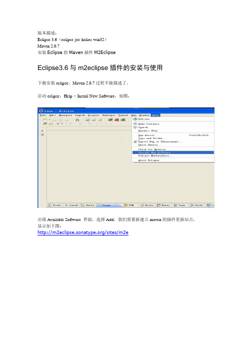
启动eclipse,Help-> Install New Software,如图:出现Available Software 界面,选择Add,我们需要新建立maven的插件更新站点,显示如下图:/sites/m2e选中需要更新的站点,点击Finish,出现如下图:Eclipse会查询到更新的插件,上边是maven插件的更新。
eclipse开始安装插件,安装完成后,需要重新启动eclipse点击Window->Preferences,如下图:可以看到maven安装成功,如下图:首次点击maven时,eclipse会根据配置的M2_HOME寻找本地资源库位置,若setting.xml 文件内本地资源库位置做了修改,eclipse会使用修改过的路径,若没做修改,会使用默认的路径,即.m2目录下的repository启动eclipse,会弹出警告框,如下图:需要修改eclipse.ini文件,加入-vm指向JDK的路径。
************************************************************************* 使用M2Eclipse插件点开src>main>webapp>手动创建一个WEB-INF的文件夹,里面创建一个web.xml 文件。
M2eclipse不会自动创建这个。
手动添加依赖如要调试运行debug要手动定位一下文件位置!下边截图是运用m2e c l i p s e插件下载依赖ja r包的源码的用法。
1.创建maven web项目并导入到eclipse中。
M2 LED Troffer安装说明书
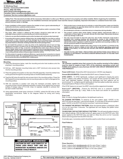
Mountinging the dimensions below,mark the mounting and wire hole locations onto the proposed mounting surface.2.Drill two,.250"diameter mounting holes and a .625"(minimum)wire access hole into the mounting surface.3.Place the gasket into position on the rear of the M2assembly.Insert the slotted hole screw grommet through the mounting holes on the M2/Gasket assembly.4.Feed the M2wires through the wire access hole in the mounting surface.Press the M2/Gasket/Grommet assembly onto its mounting location so that it is flat against the mounting surface.5.With the assembly in position and using the hardware provided,tighten the mounting screws until the lighthead assembly is drawn firmly against the mounting surface.A torque value of 12in-lb.(max.)is typically required to achieve this.DO NOT OVER TIGHTEN!ing appropriately sized wires (minimum 18AWG),extend the M2wires to their designated connections.Refer to the diagram below for wiring and fusing information.©2011 Whelen Engineering Company Inc.Form No. 14474A (121817)M2 Series LED Lighthead (24-Volt)For warranty information regarding this product, visit /warrantyWiringAll customer supplied wires that connect to the positive terminal of the battery must be sized to supply at least 125%of the maximum operating current and FUSED at the battery to carry that load.DO NOT USE CIRCUIT BREAKERS WITH THIS PRODUCT!Power (LED Color)-Extend the LED Colored wire to +24VDC (see diagram).Ground (BLACK/WHITE)-Extend the BLK/WHT wire to Chassis Ground.SYNC (GREY)-To SYNC lightheads,configure each lighthead to display the same Phase 1pattern (see pattern list below).Turn power off and connect the GREY wire from each lighthead together.Activate the lightheads and their patterns will be synchronized.To configure specific lightheads so that their patterns alternate,advance those lightheads to Phase 2of the current pattern.If the SYNC feature is not used,the GREY wire should be capped and insulated.Scan-Lock™(WHT/VIO)-Extend the WHT/VIO wire to a customer supplied momentary switch (fuse @1amp).Refer to the Scan-Lock section for operational information.Scan-LockNote:In order to change flash patterns,the lighthead must be on.TO CHANGE PATTERNS:To advance to the next pattern apply +24VDC to the WHT/VIO wire for less than 1second and release.To cycle back to the previous pattern apply +24VDC to the WHT/VIO wire for more than 1second and release.TO CHANGE THE DEFAULT PATTERN:When the desired pattern is displayed,allow it to run for more than 5seconds.The lighthead will now display this pattern when initially activated.TO RESTORE THE FACTORY DEFAULT PATTERN:This will reset all patterns back to their default settings.With the light turned off,apply power to the WHT/VIO wire.With power applied to the WHT/VIO wire,turn light on.Allow the unit to run for 3seconds before removing power from the WHT/VIO wire.Anormally open,momentary switch should be used to control Scan-Lock operation.Flash Patterns -SYNC Patterns1.SignalAlert™75Phase 12.SignalAlert 75Phase 2etFlash®75Phase 1etFlash 75Phase 25.DoubleFlash 75Phase 16.DoubleFlash 75Phase 27.SingleFlash 75Phase 18.SingleFlash 75Phase 2Alert™Phase Alert Phase 211.LongBurst™Phase 112.LongBurst Phase 213.PingPong™Phase 114.PingPongPhase 2Non-SYNC Patterns15.SingleFlash 6016.SingleFlash 9017.SingleFlash 12018.SingleFlash 30019.DoubleFlash Alert 15021.ActionFlash™122.ActionFlash 223.ModuFlash™24.ActionScan™25.SteadyPhase Operation -Phase 1 patterns flash with the same Phase 1 pattern.simultaneously Phase 2 patterns flash with the same Phase 2 pattern.simultaneously Phase 1 patterns will with Phase 2 of the same pattern.alternateSafety First: This document provides all the necessary information to allow your Whelen product to be properly and safely installed. Before beginning the installation and/or operation of your new product, the installation technician and operator must read this manual completely. Important information is contained herein that could prevent serious injury or damage.•Proper installation of this product requires the installer to have a good understanding of automotive electronics,systems and procedures.•Whelen Engineering requires the use of waterproof butt splices and/or connectors if that connector could be exposed to moisture.•Any holes,either created or utilized by this product,should be made both air-and watertight using a sealant recommended by your vehicle manufacturer.•Failure to use specified installation parts and/or hardware will void the product warranty!•If mounting this product requires drilling holes,the installer MUST be sure that no vehicle components or other vital parts could be damaged by the drilling process.Check both sides of the mounting surface before drilling begins.Also de-burr any holes and remove any metal shards or remnants.Install grommets into all wire passage holes.•Do not install this product or route any wires in the deployment area of your air bag.Equipment mounted or located in the air bag deployment area will damage or reduce the effectiveness of the air bag,or become a projectile that could cause serious personal injury or death.Refer to your vehicle owner's manual for the air bag deployment area.The User/Installer assumes full responsibility to determine proper mounting location,based on providing ultimate safety to all passengers inside the vehicle.•For this product to operate at optimum efficiency,a good electrical connection to chassis ground must be made.The recommended procedure requires the product ground wire to be connected directly to the NEGATIVE (-)battery post.•If this product uses a remote device to activate or control this product,make sure that this control is located in an area that allows both the vehicle and the control to be operated safely in any driving condition.•Do not attempt to activate or control this device in a hazardous driving situation.•This product contains either strobe light(s),halogen light(s),high-intensity LEDs or a combination of these lights.Do not stare directly into these lights.Momentary blindness and/or eye damage could result.•Use only soap and water to clean the outer e of other chemicals could result in premature lens cracking (crazing)and discoloration.Lenses in this condition have significantly reduced effectiveness and should be replaced immediately.Inspect and operate this product regularly to confirm its proper operation and mounting condition.Do not use a pressure washer to clean this product.•WARNING!All customer supplied wires that connect to the positive (+)terminal of the battery must be sized to supply at least 125%of the maximum operating current and FUSED “at the battery”to carry that load.DO NOT USE CIRCUIT BREAKERS WITH THIS PRODUCT!•FAILURE TO FOLLOW THESE PRECAUTIONS AND INSTRUCTIONS COULD RESULT IN DAMAGE TO THE PRODUCT OR VEHICLE AND/OR SERIOUS INJURY TO YOU AND YOUR PASSENGERS!®ENGINEERING COMPANY INC.51 Winthrop RoadChester, Connecticut 06412-0684Phone: (860) 526-9504SalesEmail:*******************CanadianSales:************************CustomerService:*******************www..comWarnings to InstallersWhelen’s emergency vehicle warning devices must be properly mounted and wired in order to be effective and safe. Read and follow all of Whelen’s written instructions when installing or using this device. Emergency vehicles are often operated under high speed stressful conditions which must be accounted for when installing all emergency warning devices. Controls should be placed within convenient reach of the operator so that he can operate the system without taking his eyes off the roadway. Emergency warning devices can require high electrical voltages and/or currents. Properly protect and use caution around live electrical connections.Grounding or shorting of electrical connections can cause high current arcing, which can cause personal injury and/or vehicle damage, including fire. Many electronic devices used in emergency vehicles can create or be affected by electromagnetic interference.Therefore, after installation of any electronic device it is necessary to test all electronic equipment simultaneously to insure that they operate free of interference from other components within the vehicle. Never power emergency warning equipment from the same circuit or share the same grounding circuit with radio communication equipment.All devices should be mounted in accordance with the manufacturer’s instructions and securely fastened to vehicle elements of sufficient strength to withstand the forces applied to the device. Driver and/or passenger air bags (SRS) will affect the way equipment should be mounted.This device should be mounted by permanent installation and within the zones specified by the vehicle manufacturer, if any.Any device mounted in the deployment area of an air bag will damage or reduce the effectiveness of the air bag and may damage or dislodge the device. Installer must be sure that this device, its mounting hardware and electrical supply wiring does not interfere with the air bag or the SRS wiring or sensors. Mounting the unit inside the vehicle by a method other than permanent installation is not recommended as unit may become dislodged during swerving; sudden braking or collision. Failure to follow instructions can result in personal injury. Whelen assumes no liability for any loss resulting from the use of this warning device. PROPER INSTALLATION COMBINED WITH OPERATOR TRAINING IN THE PROPER USE OF EMERGENCY WARNING DEVICES IS ESSENTIAL TO INSURE THE SAFETY OF EMERGENCY PERSONNEL AND THE PUBLIC.Warnings to UsersWhelen’s emergency vehicle warning devices are intended to alert other operators and pedestrians to the presence and operation of emergency vehicles and personnel. However, the use of this or any other Whelen emergency warning device does not guarantee that you will have the right-of-way or that other drivers and pedestrians will properly heed an emergency warning signal. Never assume you have the right-of-way. It is your responsibility to proceed safely before entering an intersection, driving against traffic, responding at a high rate of speed, or walking on or around traffic lanes. Emergency vehicle warning devices should be tested on a daily basis to ensure that they operate properly. When in actual use, the operator must ensure that both visual and audible warnings are not blocked by vehicle components (i.e.: open trunks or compartment doors), people, vehicles, or other obstructions. It is the user’s responsibility to understand and obey all laws regarding emergency warning devices.The user should be familiar with all applicable laws and regulations prior to the use of any emergency vehicle warning device. Whelen’s audible warning devices are designed to project sound in a forward direction away from the vehicle occupants. However, because sustained periodic exposure to loud sounds can cause hearing loss, all audible warning devices should be installed and operated in accordance with the standards established by the National Fire Protection Association.。
ZHIYUN CRANE-M2 说明书
此PDF电子文档支持以下功能**需阅读软件支持,以AdobeReader为例。
CRANE-M2说明书Z H I Y U N -C N -v 1 . 3 0Contents■产品清单产品清单 (1)■认识CRANE-M2认识CRANE-M2 (2)■电池及充电说明电池及充电说明 (3)■安装及调平安装三脚架 (4)安装相机 (4)安装GoPro相机 (5)安装手机 (5)平衡调节 (6)■稳定器的使用控制按键说明 (8)显示屏界面说明 (9)菜单选项说明 (10)电机力度参数调节 (10)工作模式说明 (11)手调定位 (13)Micro USB电源输出接口的使用 (13)■APP的使用下载APP (14)如何连接 (14)后续连接时 (16)APP主要功能介绍 (16)■校准与固件升级哪种情况下需要校准 (17)初始化方法 (17)六面校准方法 (17)电机微调 (19)稳定器固件升级 (19)■参数说明■免责声明与警告■保修卡■联络卡产品清单产品清单使用本产品前,请仔细检查产品包装内是否包含以下所有物品,若有缺失,请联系客服或您的代理商。
认识CRANE-M2认识CRANE-M21. 俯仰轴锁紧螺钉2. 快装板锁紧螺钉3. 航向轴锁定开关4. 扳机键5. 收纳锁定针6. 横滚轴定位螺钉7. 快装板8. 1/4相机固定螺钉9. 航向轴锁紧螺钉10. 1/4拓展接口11. 充电/固件升级接口12. 变焦控制杆13. 挂绳口14. M icro USB电源输出接口15. 横滚轴锁紧螺钉16. 横滚轴电机17. 航向轴电机18. 显示屏19. 云台摇杆20. 拍照/录像键21. 俯仰轴电机22. 安全锁23. 电源键24. 菜单键25. 模式键26. 三脚架电池及充电说明CRANE-M2使用内置电池,首次使用前,请先给CRANE-M2充满电以激活电池,保证产品顺利使用。
充电方法:使用包装内提供的Type-C USB 数据线连接电源适配器(自备)与稳定器手柄接口即可。
睿奥M2安装配置及操作指南

睿奥M2 云智能信息化管理平台的安装、配置及常见问题
解决操作指南
一、M2 系统的安装
在安装M2 软件之前,用户必须要先安装好Microsoft SQL server 数据库,下面主要分两
部分介绍:
1.1 Microsoft SQL server 数据库安装
M2 软件支持MS-SQL2000、2005 、2008 各个版本数据库,如果是XP 操作系统,建议安
装MS SQL2000,WIN7 及以上系统(32 位或64 位都可以),建议安装MS-SQL2008。
双击下载好的安装文件setup.exe,(注意:安装之前请确认是否有安装SQL Server 2008 R2 需要的.NET Framework 3.5 SP1 ,)弹出sql server 安装中心界面,点击左侧栏目“安装”,点击右边栏目的“全新安装或向现有安装添加功能”。
选择输入产品密钥,并输入密钥,并接受许可条款,并点击下一步,选择安装,
选中默认:sql server 功能安装,并点击下一步
功能选择:点击全选按钮,(共享功能目录看个人意愿是否需要修改到其他盘)并点击下一步
实例配置,如果目录需要修改可以更改为其他路径,然后点击下一步如图修改下账户名,然后点击下一步
账户设置:选择混合模式,输入密码和确认密码;
点击下方:添加当前用户
数据目录,默认保存在 c 盘,建议修改保存目标路径,点击下一步选择安装本机模式默认配置
下一步,直到此界面,选择安装即可。
经过一段时间后,SQL2008 数据库安装完成,打开数据库管理工具就可以使用了。
Sun Fire X2200 M2服务器安装指南说明书
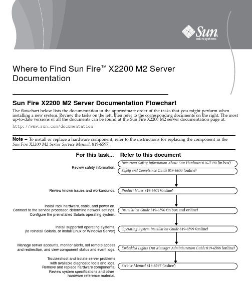
Sun Fire X2200M2Server Documentation FlowchartThe flowchart below lists the documentation in the approximate order of the tasks that you might perform when installing a new system.Review the tasks on the left,then refer to the corresponding documents on the right.The most up-to-date versions of all the documents can be found at the Sun Fire X2200M2server documentation page at:/documentationNote –To install or replace a hardware component,refer to the instructions for replacing the component in the Sun Fire X2200M2Server Service Manual ,819-6597.Review safety information.Install rack hardware, cable, and power on.Connect to the service processor, determine network settings.Configure the preinstalled Solaris operating system.Install supported operating systems.(to reinstall Solaris, or install Linux or Windows Server)Review known issues and workarounds.Manage server accounts, monitor alerts, set remote accessand redirection, and view component status and event logs.Troubleshoot and isolate server problemswith available diagnostic tools and logs.Remove and replace hardware components.Review system specifications and otherhardware reference material.Important Safety Information About Sun Hardware 816-7190 (in box)For this task...Safety and Compliance Guide 819-6600(online)Refer to this document Product Notes 819-6601(online)Installation Guide 819-6596 (in box and online)Operating System Installation Guide 819-6599 (online)Embedded Lights Out Manager Administration Guide 819-6588 (online)Service Manual 819-6597 (online)Where to Find Sun Fire ™X2200M2ServerDocumentationPart No. 819-6598-10, Rev. A July 2006Sun Microsystems, Copyright 2006Sun Microsystems,Inc.All rights e is subject to license terms.Third-party software,including font technology,is copyrighted and licensed from Sun suppliers.Portions may be derived from Berkeley BSD systems,licensed from U.of CA.Sun,Sun Microsystems,the Sun logo,Sun Fire,and Solaris are trademarks or registered trademarks of Sun Microsystems,Inc.in the U.S.and in other countries.All SPARC trademarks are used under license and are trademarks or registered trademarks of SPARC International,Inc.in the U.S.and in other ernment Rights—Commercial ernment users are subject to the Sun Microsystems,Inc.standard license agreement and applicable provisions of the FAR and its supplements.Copyright 2006Sun Microsystems,Inc.Tous droits réservés.Distribuépar des licences qui en restreignent l’utilisation.Le logiciel détenu par des tiers,et qui comprend la technologie relative aux polices de caractères,est protégépar un copyright et licenciépar des fournisseurs de Sun.Des parties de ce produit pourront être dérivées des systèmes Berkeley BSD licenciés par l’Universitéde Californie.Sun,Sun Microsystems,le logo Sun,Sun Fire,et Solaris sont des marques de fabrique ou des marques déposées de Sun Microsystems,Inc.aux Etats-Unis et dans d’autres pays.Toutes les marques SPARC sont utilisées sous licence et sont des marques de fabrique ou des marques déposées de SPARC International,Inc.aux Etats-Unis et dans d’autres pays.Downloading Sun Fire X2200M2Server Product UpdatesFor product updates,go to the following URL and navigate to the page for this product:/servers/index.jspContacting Sun Technical SupportIf you have technical questions about this product that are not answered in this document,go to:/service/contacting。
Moen M22020 安装说明书-(9-23)
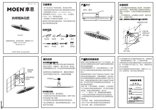
产品售后保修条款摩恩产品是在高质量标准及生产工艺下制造的,摩恩承诺为消费者购买的洁具产品提供有期限免费保修及终身维修服务。
花洒免费保修期为1年,均自消费者购买日(以摩恩产品分销商开具的发票或收据上载明日期为准)起计。
免费保修范围为产品及产品配件由于材质及工艺原因而造成的故障或损坏。
免费保修期内,我们将无偿为您提供修理服务及更换发生故障的产品或产品配件。
摩恩的售后服务责任仅限于对故障产品的修理,而不延及您因产品故障而发生的其他损失,法律另有规定的除外。
您需了解:产品外观碰伤、刻划痕迹,以及滥用及不正当保养所导致的故障或损坏,均不属于免费保修范围。
即使在免费保修期内,属下列(1)-(5)情况之一的,需酌情收取修理费用:1.不能出示相符的保修卡和有效购买凭证情况的,2.未按使用说明书告知的使用方法和注意事项造成的故障,平网垫片清洗说明当感觉淋浴出水量明显减少时,请取出花洒进水口处的平网垫片冲洗干净,以避免杂质堵塞。
如何清洁花洒:• 为保持花洒洁净,请定期清洁。
• 先用清水或中性的液体清洁剂清洗,再用干净的软布彻底擦干整个表面。
如何清除出水口水垢:出水孔在使用一段时间后可能会堆积杂质或结垢,导致水流变形、流量减小。
请打开水源,用力按压和摩擦橡胶出水孔, 可以轻松将杂质或结垢清除。
MOEN LIMITED WARRANTYWe offer limited warranty and lifetime maintenance for Moen products, which are all manufactured with high standards of workmanship.The period of warranty shall start from the date of purchase of the product (according to the invoice or receipt issued by Moen distributors) and shall cover a period of the following: the warranty period for shower is 1 year.This warranty is your coverage against material and workmanship malfunction or defects in Moen products or components. During the warranty period, we offer free main tenance and changing of malfunctioned products or product components. Moen’s after sales service liability is limited to the maintenance of faulty items and does not cover your other losses caused by product malfunction, except for other wise stipulated by law.Cosmetic damages (scratches, dents, etc.) andmalfunction or defects caused by abuse or improper maintenance is not covered by this warranty. Although the warranty period remains valid, in case of the following conditions (1) - (5), the maintenance cost (material cost and labor cost) shall still be charged as the case may be:1.Corresponding warranty card and valid invoice cannot Screen WasherWhen you find that the amount of water is reduced significantly, please take out the flat ScreenWasher and rinse it to avoid clogging by impurities.How to Clean the Nozzles:Any debris or mineral build-up may cause theflow stream to become distorted or reduce the flowrate. To remove the debris or mineral build-up, please turn on the water source and press and rub the rubber water outlet firmly.How to Clean the Shower Body:• Keep the product clean with clean water or mild liquiddet ergent regularly.• Rinse it with clean water or mild liquid, and then Cleaning Instructions。
车厘子m2行车记录仪安装教程

车厘子m2行车记录仪安装教程一、确定安装的位置行车记录仪安装的位置,越靠近车内后视镜越好——一来居中拍摄的角度更大,二来安装在内后视镜附近对前挡视线的影响是最小的。
把行车记录仪安装在内后视镜与前挡玻璃之间,属于最居中的位置。
安装在这个位置时要注意,如果记录仪与内后视镜挨得太近,可能会影响内后视镜的调整角度。
二、需要用到的工具:一般用不到工具,空手就能搞定。
部分车型可能会用到十字或一字改锥。
三、具体的安装走线方法:1、确定行车记录仪的最佳安装位置,建议安装在车内后视镜的右侧,尽量靠中间一些,这样拍摄的角度才会比较正,同时也更具有参考价值。
2、根据电源线的长度来确定最佳布线方案,建议先模拟走一遍线,以确定电源线是否足够长。
3、在确定行车记录仪的安装位置及走线方案后,第一步就是将记录仪的电源线塞进车顶棚的缝隙内。
4、将车顶的线塞进去之后,就需要把门框密封条拽下来,之后双手用力扒开A柱饰板,大部分车A柱饰板是用卡扣固定的。
5、拆A柱饰板的目的并不是为了把线放在A柱内,因为不少车型带有侧气帘,怕影响安全,只是为了能让电源线顺利通过,之后将线塞入门框密封条内,将A柱卡扣对准,用拳头轻轻将A柱饰板敲进去。
6、从A柱上端顺着门框向下,一边装密封条,一把将电源线塞入密封条内,直到仪表台最底端将线甩出来。
7、将电源线穿过手套箱后边,可以根据不同车型的实际情况,把线固定在手套箱背后,或者藏在防火墙或地胶底下,这一步虽然麻烦一些,但视觉效果会最好。
8、为了让点烟器附近看不出有太多的明线,需要把中控台下边的饰板螺丝拧松,扒开一点小缝隙,把线塞入缝隙内再将螺丝拧紧即可,不过车型众多需要自己灵活多变。
9、将点烟器电源插上,确认行车记录仪能通电并能正常启动后,安装布线大功告成。
M2 NMI Extension 2023 安装指南说明书

NMI PAYMENT GATEWAY FOR MAGENTO 2INSTALLATION GUIDE•Insert the Access Keys of Magento Marketplace into the auth.json file of your Magento website. Below are steps of how to get Access Keys.•Log in to your Magento Marketplacehttps:/// (Only log in to the account fromwhere you purchased our extension)•Navigate to My Profile -> Access Keys•Paste the access keys in your auth.json file inside your project.(auth.json file is located in your website root directory where theapp, vendor, var, pub, lib etc. folders are located)•Run the composer command to install the module. Below are steps on how to run the composer command.•Connect to SSH of your website.•Navigate to Magento root directory where the app, vendor, var, pub, lib etc. folders are located.•Now you have to run the composer command as shown below.Systax: composer require <module_name>:<version>Where,<module_name> = The name of the module you purchase.<version> = The version of the module which you wanted to install.You can get the module composer name and version fromMagento Marketplace -> My Profile -> My PurchasesActual Command to Install NMI Extension:composer require:rootways/module-nmi:2.0.0NOTE: Please check the latest version of the extension and replaceit with 2.0.0 before running the above command.•Known issues: Package not found.When you run the composer command to install the module, the mostknown issue is that the package is not found. This is because you are using the wrong access key (public and private keys) of your Magentomarketplace account.Please double-check the public and private key added to auth.json file of your website is taken from the Magento account from where youpurchased this extension. If the keys do not match, then you can notinstall the module and it will show the package not found error.•Run the below command to activate the module.php bin/magento module:enable Rootways_Nmiphp bin/magento setup:upgradeOnly run the below command if your Magento mode is in productionphp bin/magento setup:static-content:deployEXTENSION LICENSE KEY•Please email us at *****************along with your order number, production domain and development/staging domain, and our team will share the license key to activate the module on your domains.*NOTE: If you are having any issues or have questions about our extension, please feel free to email us at *****************with all your questions and we will be more than happy to assist you.。
- 1、下载文档前请自行甄别文档内容的完整性,平台不提供额外的编辑、内容补充、找答案等附加服务。
- 2、"仅部分预览"的文档,不可在线预览部分如存在完整性等问题,可反馈申请退款(可完整预览的文档不适用该条件!)。
- 3、如文档侵犯您的权益,请联系客服反馈,我们会尽快为您处理(人工客服工作时间:9:00-18:30)。
GE Energy ServicesHYDRAN®M2Fault Gas and Moisture MonitorHYDRAN®M2故障气体及微水监测仪Installation Guide中文说明书前 言本手册是HYDRAN®M2的安装概述。
有关安装过程的详细解释请参考HYDRAN®M2指导手册第三章。
本手册的使用人员包括:• 安装人员• 电气工程师警告:应该严格遵守本手册的所有程序。
任何与程序不符的行为可能会导致所监测变压器或HYDRAN®M2不可逆转的损坏。
一旦发现运输包装箱有任何外观损坏,请立即与中能公司联系。
请妥善保存所有的文档(产品系列号,手册等),便于参考和质保。
为便于阅读,手册前面部分列出了目录和所有的图表。
目 录前言 . . . . . . . . . . . . . . . . . . . . . . . . . . . . . . . . . . . . .1 目录 . . . . . . . . . . . . . . . . . . . . . . . . . . . . . .2 图表列表 . . . . . . . . . . . . . . . . . . . . . . . . . . 3第一章 常规警告第二章 安装2.1 概述. . . . . . . . . . . . . . . . . . . . . . . . . . . .10 2.2 将HYDRAN®M2安装至阀门. . . . . . . . . . .. . .. . . . .15 2.3 安装电缆 . . .. . . . . . . . . . . . . . . . . . . . . .22第三章 软件配置3.1 设置日期和时间 . . . . . . . . . . . . . . . . . . . . . 29 3.2 测试传感器 . . . . .. . . . . . . . . . . . . . . . . . .30 3.3 设置气体含量报警参数. . . . . . . . . . . . . . . . . . . 31 3.4 设置水分含量报警参数. . . . . . . . . . . . . . . . . . . 33 3.5 设置网络通信参数 . . . . . . . . . . . . . . . . . . . . 34 3.6 固定外壳 . . . . . . . . . . . . . . . . . . . . . . . . 36 3.7 试运行. . . . . . . . . . . . . . . . . . . . . . . . . . . . .37附录A 通信和网络2图 表 列 表图1-1 传感器安装在阀门上前不要拆除塑料盖. . .. . . . .. . . . 5 图1-2 禁止用手指或其它物体触摸传感器膜. .. . . .. . . . . . . 5 图1-3 禁止堵塞传感器的通气孔或刺穿通气孔薄膜. . . . . . . . . 6 图1-4 禁止垂直安装HYDRAN®M2. . . . . . . . . . . . . . . ... .6 图1-5 禁止在弯管或配件盒处安装HYDRAN®M2. . . . . . . . . . . 7 图1-6 禁止将HYDRAN®M2置于真空,禁止在冷却泵入口侧安装HYDRAN®M2. . . . . . . ... . . . 7 图1-7 关闭阀门后应该立即移去放油螺钉. . . . . . .. . . . . . . .8 图1-8 禁止高压水流接触HYDRAN®M2或其传感器. . . . . . . . . . .8 图1-9 禁止粉刷传感器或使用溶剂清洗传感器. . . . . . . . . . .9 图2-1 M2的典型安装. . . . . . . . . . . . . .. . . . . . . . .10 图2-2 HYDRAN®M2在变压器上的安装位置. . . . . . . . . . . . . 11 图2-3 HYDRAN®M2安装在正常位置时的顶部与底部的间隙尺寸. . . 13 图2-4 HYDRAN®M2安装在倒置的位置时顶部与底部的间隙尺寸 . . 13 图2-5 安装所需的工具. . . . . . . . . . . . . . . . . . . . 14 图2-6 将传感器从HYDRAN®M2上分离开来 . . . . . . . . . . . 15 图2-7 将传感器的电缆断开. . . . . . . . . . . . . . . . . . 16 图2-8 通常将传感器的螺口绕上Teflon的胶带 . . . . . . . . .. . 16 图2-9 将传感器安装到阀门上并用猴形钳拧紧. . . . . . . . (17)图2-10 放油螺孔必须位于上方12点钟的位置 . . . . . . .. . . 17 图2-11 打开阀门将传感器中的空气排出. . . . . . . . . . . .. . 18 图2-12 将HYDRAN®M2 固定到传感器上- 闸式阀门的安装. . . . .. 19 图2-13 将HYDRAN®M2 固定到传感器上- 球形阀门的安装. . . . ..20 图2-14 将HYDRAN®M2 固定到传感器上(第二部分) . . . . . . . .21 图2-15 将HYDRAN®M2 外壳接地. . . . . . . . . . . . . . . . . . ..21 图2-16 除去HYDRAN®M2外壳 . . . . . . . . . . . . . . .. . . . . .22 图2-17 安装电缆导管. . . . . . . . . . . . . . . . . . . .. 22 图2-18 在右侧安装电缆- 可选的TDM 信号. . . . . . . . . . .. 233图2-19 在右侧安装电缆- 可选的RS-485 网络联接. . . . . . . ..23 图2-20 HYDRAN®M2用485网络连接时的接线. . . . . . . . . . . ..24 图2-21 在右侧安装电缆--可选的模拟输入. .. . . . . . . . . (24)图2-22 自供电、可选的模拟输入的接线. . . . . . . . . . . .. 25 图2-23 双线式、环形供电、可选的模拟输入的接线 . . . . . . . ..25 图2-24 三线式、环形供电、可选的模拟输入的接线. . . . . . . . . ..26 图2-25可选的模拟输出终端模块的接线. . . . . . . . . . . . . . .26 图2-26在左侧安装电缆--可选的报警继电器 . . . . . . . . . . . ..27 图2-27在左侧安装电缆---交流电源供应 . . . . . . . . . .. . . .27 图3-1 用户界面简图 . . . . . . . . . . . . . . . . . . .. . . . . ..28 图3-2 显示界面 . . . . . . . . . . . . . . . . . . . . . . . . ..28 图3-3 设置正确的日期与时间 . . . . . . . . . . . . . . . . . ..29图3-4 测试传感器 . . . . . . . . . . .. . . . . . . . . . . .30 图3-5 设置气体报警参数 (第一部分) . . .. . . . . . .. . . . (31)图3-6 设置气体报警参数 (第二部分). . . .. . . . . . . . . . 32 图3-7 设置水分报警参数 . .. . . . . . . .. . . . . . . . ... . .33 图3-8 设置网络通讯参数(第一部分) . . . . . . . . . . . . . . ..34 图3-9 设置网络通讯参数(第二部分) . . . . . . . . . . . . .. 35 图3-10 安装外壳 . . . . . . . . . . . . . . . . . . . .. 36 图3-11 等待2小时 . . . . . . . . . . . . .. . . . . . . . . ..37 图3-12 将气体读数与最近的DGA数据或HYDRAN®103B读数进行比较. .37 图A-1 网络简图(设备串接) . . . . . . . . . . .. . . . . . . . .38 图A-2 与计算机进行本地通讯 . . . . . . . . . . . . . . . .38 图A-3 与主机进行远程通讯. . . . . . . . . . . . . . . . . .38 图A-4 HYDRAN®M2和HYDRAN®201C i 控制器连接的详细接线图. . . . .394第一章 常规警告警告:错误操作HYDRAN®M2传感器(刺穿薄膜,将传感器放置于真空,粉刷传感器,使用溶剂清洗传感器)将不能得到质保。
警告:推荐在安装前阅读HYDRAN®M2指导手册的所有警告和注意事项。
图1-1 传感器安装在阀门上前不要拆除塑料盖图1-2 禁止用手指或其它物体触摸传感器膜图1-3 - 禁止堵塞传感器的通气孔或刺穿通气孔薄膜5图1-4 禁止垂直安装HYDRAN® M2图1-5 禁止在弯管或配件盒处安装HYDRAN® M2图1-6 禁止将HYDRAN® M2置于真空;禁止在冷却泵入口侧安装HYDRAN® M26图1-7 关闭阀门后应该立即移去放油螺钉图1-8 禁止高压水流接触HYDRAN®M2或其传感器图1-9 禁止粉刷传感器或使用溶剂清洗传感器78第二章 安装2.1 概述图2-1 M2的典型安装对于一个典型的变压器而言,有四个最普通的位置用于安装HYDRAN M2,见图2。
具体内容可参考表2-1。
☆☆☆ 推荐位置 ☆☆ 很好的替换位置 ☆ 好的替换位置注意:一定要保证有足够的空间来 安装或拆除HYDRAN M2的外壳图2-2 HYDRAN M2 在变压器上的安装位置注意: 如果上述这些不可利用,请联系中能公司工程部以帮助你决定选择一个可替代的位置。
