SFF1006G中文资料
丹福斯高标准钢管适配器产品简介说明书

Welcome to the higher standard for steel adapters BrochureWelcome to the higher standard for steel adaptersHigher pressure.Higher performance.Beyond SAE certified.Danfoss expands your possibilities.With more than 3000 steel adapter part numbers globally, Danfoss has a wide variation of configurations with large portfolio of ORFS, JIC, BSPP , NPTF, and manyother terminal ends.Expand the equation.Same exceptional Danfoss adapters —now with outstanding corrosion resistance.Achieve operating pressures up to 125% more than SAE.Dura-Kote plating technology.Danfoss Competitor B Competitor Pan assembly that can perform up to 125% greater operating pressureCarbon steel corrosion protection This is a comparison of current carbon steel adaptersafter 650-hours of exposure to salt spray testing which far exceeds the SAE standard of 72-hours. Carbon steelfluid conveyance products protected with Danfoss’Dura-Kote plating technology resist rust longer than other carbon steel products available today.Discover the additional value of using a Danfoss system of products designed to work together to achieve even higher operating pressures. When Danfoss hoses are combined with Danfoss 1A or 4S/6S fittings and Danfoss adapters, assemblies can perform up to 125% higher pressures than the SAE rating.Danfoss adapters now come with Dura-Kote ® plating, which gives you up to 1,000 hours of corrosion resistance. Dura-Kote is an innovative plating technology for steel adapters, offering more corrosive protection for longer life, lower replacement costs, and improved appearance. This corrosion protection decreases the likelihood of leaking, meaning less equipment downtime and greater productivity. Plus, there are no compatibility issues with Dura-Kote plating. The Danfoss adapters you rely on today will look, feel, and perform exactly the same.Many companies offer extra plating services and special requests to enhance corrosion resistance. Requesting extra services can delay your order, complicate delivery, and add significantly to your costs. That is why Danfoss has responded to the needs of the market and simplified the entire process. With Dura-Kote plating now standard on Danfoss adapters, you’ll get products that look better, last longer, and cost less to maintain, which gives you and your customers one less thing to worry about. ++=Same form and functional capabilities Same torque values and pressure ratings Same silver appearance Same procedures for assemblyFor over 90 years, Danfoss has continued to manufacture and supply the highest performing quick disconnect couplings for customers globally. Danfoss’ quality and performance are never compromised when it comes to engineering and manufacturing its full line of quick disconnect couplings. From traditional industry standards to custom couplings for the next generation of emerging markets and new advanced technologies, Danfoss continues to provide quick disconnect coupling solutions to meet your demands. Quick Disconnect Coupling applications:• Hydraulic applications in construction, agriculture, etc. • Fluid transfer • Liquid cooling • Pneumatic • Chemical • Oil and Gas • Aerospace • Medical • Food and Beverage • Law enforcement/rescueCheck out our complete portfolio of Quick Disconnect Couplings found in our catalog at .Literature number: AF435258198969en-000101Patented STC Snap-To-Connect products are threadless connectors that keep equipment up and running longer with simple, leak-free connections.Danfoss has the broadest range of threadless connectors in the industry. Our patented STC technology excels in rigorous mobile application in agriculture, construction, forestry, transportation, utility, and lawn and turf. Because of their easy installation — even in confined spaces — and virtually zero-leak performance (per SAE J1176), more than 25 million STC connections are currently in use worldwide.STC benefits:• Fast reliable one-hand connections requiring no assembly tools • Eliminates cross-threading, over or undertorquing, and hose twisting • Virtually zero leak performance • Direct porting eliminates adapters to maximize cost savings • Resists external contamination • Allows easy disconnection with release toolA full list of available STC products can be found in our catalog at .Literature number: AF444058468933en-000101Making the right connections is easy with Danfoss’ Waltech metric tube fittings. A variety of available sizes and configurations make Danfoss’ metric tube fittings a simple, flexible and cost-effective solution for many applications. With three unique systems — including Walpro ®, WalringPlus ®, and Walform ® — each tube fitting is manufacturered to meet DIN 2353 and ISO 8434-1 standards and withstand pressure and corrosion with best-in-class performance. Metric tube fitting applications:• Harvester/balers • Machine tool • Hydraulic presses • Excavators • Loaders • Mining equipment • Mining equipment • Concrete pumpers • Off-shore equipmentLearn more about Danfoss’ entire line of metric tube fittings by reviewing our Waltech Metric Tube Fittings catalog at .Literature number: AF403661682130en-000201Regardless of the job, Danfoss has the right products to meet the challenge every time.Additional products available from Danfoss.Danfoss Quick Disconnect CouplingsWaltech Metric Tube FittingsDanfoss STC Snap-To-ConnectWalpro WalformWalringPlusAD440177948096en-000101© Danfoss | Power Solutions | April 2023Any information, including, but not limited to information on selection of product, its application or use, product design, weight, dimensions, capacity or any other technical data in product manuals, catalogues descriptions, advertisements, etc. and whether made available in writing, orally, electronically, online or via download, shall be considered informative, and is only binding if and to the extent, explicit reference is made in a quotation or order confirmation. Danfoss cannot accept any responsibility for possible errors in catalogues, brochures, videos and other material. Danfoss reserves the right to alter its products without notice. This also applies to products ordered but not delivered provided that such alterations can be made without changes to form, fit or function of the product. All trademarks in this material are property of Danfoss A/S or Danfoss group companies. Danfoss and the Danfoss logo are trademarks of Danfoss A/S. All rights reserved.Danfoss Power Solutions, Nordborgvej 81, 6430 Nordborg, Denmark, Tel. +45 74 88 22 22, Fax +45 74 65 25 80,E-mail:****************。
Nff 00608 套管

NF F 00-608标记热缩套管(manchon)和热缩套管(gaine)1适用范围本文定义了,铁路设备中使用的-标记用的热缩套管(manchon)-用于机械和电气保护的无粘合剂的热缩套管(gaine)的特性,认证条件,试验,条件和运输它被NF F 61-010标准《一般布线规则》所推荐。
23定义本文所需的定义如下:膨胀状态:产品送货时的状态自由热缩状态:在不用导线或者其他物品的情况下,产品最大热缩4命名法一个本文所讨论的标记热缩套管的命名包括:-字母GT表示热缩套管,字母MRT表示标记热缩套管-接着一个字母表示其使用功能- A表示不耐在可燃性液体- H表示耐在可燃性液体-内径,单位mm,在膨胀状态时-壁厚,单位mm,在自由缩进状态时-缩进系数:2/1,3/1,4/1等等-本文参考例子1:GT.A.7.5-0.3-3/1-NF F 00-608热缩套管(gaine),不耐可燃性液体,膨胀状态时内径7.5mm,自由缩进状态时壁厚0.3mm,缩进系数3/1,符合NF F 00-608标准例子2:MRT.H.9.5-0.75-2/1-NF F 00-608标记热缩套管(manchon),耐可燃性液体,膨胀状态时内径9.5mm,自由缩进状态时壁厚0.75mm,缩进系数2/1,符合NF F 00-608标准标记套管5特性5.1组成材料热缩套管(gaine)和标记热缩套管(manchon)使用基于弹性体或塑性体或两者混合物的材料。
5.2表面热缩套管(gaine)和标记热缩套管(manchon)表面不应该粗糙。
A和H型热缩套管(gaine)应该是黑色,如果订单中制定了另外的颜色,那他应该符合CEI 304公布文件中所定义的,不包括:土耳其色,紫色,粉红色和橙色。
A型标记热缩套管(manchon)是白色的,H型标记热缩套管(manchon)是黄色的。
表面检查指导见11.1章节。
5.3几何特性5.3.1尺寸膨胀状态时的内径,不能低于供应商确定的值。
SF605中文资料
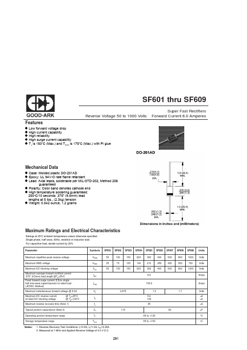
Maximum Ratings and Electrical Characteristics
Ratings at 25oC ambient temperature unless otherwise specified. Single phase, half wave, 60Hz, resistive or inductive load. For capacitive load, derate current by 20%
C C
o
Notes:
1. Reverse Recovery Test Conditions: IF=0.5A, IR=1.0A, IRR=0.25A 2. Measured at 1 MHz and Applied Reverse Voltage of 4.0 V D.C.
291
元器件交易网
150.0 1.3 1.7
Amps Volts uA uA nS F
o
Maximum reverse recovery time (Note 1) Typical junction capacitance (Note 2) Operating junction temperature range Storage temperature range
Parameter Maximum repetitive peak reverse voltage Maximum RMS voltage Maximum DC blocking voltage Maximum average forward rectified current .375" (9.5mm) lead length @TA=55oC Peak forward surge current, 8.3ms single half sine-wave superimposed on rated load (JEDEC Method) Maximum instantaneous forward voltage @ 6.0A Maximum DC reverse current at rated DC blocking voltage @ TA=25oC @ TA=100oC Symbols VRRM VRMS V DC I(AV) IFSM VF IR trr CJ TJ TSTG 115 -55 to +125 -55 to +150 0.975 5.0 100 35 60 SF601 50 35 50 SF602 100 70 100 SF603 150 105 150 SF604 200 140 200 SF605 300 210 300 6.0 SF606 400 280 400 SF607 600 420 600 SF608 800 560 800 SF609 1000 700 1000 Units Volts Volts Volts Amps
FortiGate 100F系列产品说明书

FortiGate ® 100F SeriesFG-100F and FG-101FThe FortiGate 100F series provides an application-centric, scalable, and secure SD-WAN solution with Next Generation Firewall (NGFW) capabilities for mid-sized to large enterprises deployed at the campus or branch level. Protects against cyber threats with system-on-a-chip acceleration and industry-leading secure SD-WAN in a simple, affordable, and easy to deploy solution. Fortinet’s Security-Driven Networking approach provides tight integration of the network to the new generation of security.NGFW Threat ProtectionInterfaces20 Gbps 2.6 Gbps 1.6 Gbps 1 GbpsMultiple GE RJ45, GE SFP and 10 GE SFP+ slotsRefer to specification table for detailsSecurity n Identifies thousands of applications inside network traffic for deep inspection and granular policy enforcementn Protects against malware, exploits, and maliciouswebsites in both encrypted and non-encrypted traffic n Prevent and detect against known and unknown attacksusing continuous threat intelligence from AI-powered FortiGuard Labs security servicesPerformancen Delivers industry’s best threat protection performance and ultra-low latency using purpose-built security processor (SPU) technologyn Provides industry-leading performance and protection forSSL encrypted trafficCertificationn Independently tested and validated best security effectiveness and performancen Received unparalleled third-party certifications from NSSLabsNetworkingn Delivers advanced networking capabilities that seamlessly integrate with advanced layer 7 security and virtual domains (VDOMs) to offer extensive deployment flexibility, multi-tenancy and effective utilization of resourcesn Delivers high-density, flexible combination of varioushigh-speed interfaces to enable best TCO for customersfor data center and WAN deploymentsManagement n Includes a management console that is effective, simple to use, and provides comprehensive network automation and visibility.n Provides Zero Touch Integration with Security Fabric’sSingle Pane of Glass Managementn Predefined compliance checklist analyzes the deploymentand highlights best practices to improve overall securitypostureSecurity Fabric n Enables Fortinet and Fabric-ready partners’ products to provide broader visibility, integrated end-to-end detection, threat intelligence sharing, and automated remediationNext Generation Firewall Secure SD-WANSecure Web GatewayDATA SHEETDATA SHEET | FortiGate® 100F SeriesDEPLOYMENTN ext Generation Firewall (NGFW)§Reduce the complexity and maximize your ROI by integrating threatprotection security capabilities into a single high-performance network security appliance, powered by Fortinet’s Security Processing Unit (SPU) §Full visibility into users, devices, and applications across the entire attack surface, and consistent security policy enforcement irrespective of asset location §Protect against network exploitable vulnerabilities with industry-validated IPS that offers low latency and optimized network performance §Automatically block threats ondecrypted traffic using the industry’s highest SSL inspection performance, including the latest TLS 1.3standard with mandated ciphers §Secure Web Gateway (SWG)§Secure web access from both internal and external risks, even for encrypted traffic at high performance §Enhanced user experience with dynamic web and video caching §Block and control web access based on user or user groups across URLs and domains §Prevent data loss and discover user activity to known and unknown cloud applications §Block DNS requests against malicious domains §Multi-layered advanced protection against zero-day malware threats delivered over the webSecure SD-WAN§Consistent business application performance with accurate detection, dynamic WAN path steering on any best-performing WAN transport §Accelerated multi-cloud access for faster SaaS adoption with cloud-on-ramp §Self-healing networks with WAN edge high availability, sub-second traffic switchover-based and real-time bandwidth compute-based traffic steering §Automated overlay tunnels provide encryption and abstracts physical hybrid WAN making it simple to manage §Simplified and intuitive workflow with SD-WAN orchestrator for management and zero touch deployment ENTERPRISE Secure Access SwitchEnterprise Branch Deployment (Secure SD-WAN)DATA SHEET | FortiGate® 100F Series FORTINET SECURITY FABRICFortiOS™Operating SystemFortiOS, Fortinet’s leading operating system enable the convergence of high performing networking and security across the Fortinet Security Fabric delivering consistent and context-aware security posture across network endpoint, and clouds. The organically built best of breed capabilities and unified approach allows organizations to run their businesses without compromising performance or protection, supports seamless scalability, and simplifies innovation consumption.The release of FortiOS 7 dramatically expands the Fortinet Security Fabric’s ability to deliver consistent security across hybrid deployment models of Hardware, Software, and Software As-a-Service with SASE and ZTNA, among others.Security FabricThe industry’s highest-performing cybersecurity platform,powered by FortiOS, with a rich ecosystem designed to span the extended digital attack surface, delivering fully automated, self-healing network security.§Broad: Coordinated detection and enforcement across the entire digital attack surface and lifecycle with converged networking and security across edges, clouds, endpoints, and users§Integrated: Integrated and unified security, operation, and performance across different technologies, location, deployment options, and the richest ecosystem§Automated: Context aware, self-healing network and security posture leveraging cloud-scale and advanced AI to automatically deliver near-real-time, user-to-application coordinated protection across the FabricThe Fabric empowers organizations of any size to secure and simplify their hybrid infrastructure on the journey to digital innovation.SERVICESFortiGuard™Security ServicesFortiGuard Labs offer real-time intelligence on the threat landscape, delivering comprehensive security updates across the full range of Fortinet’s solutions. Comprised of security threat researchers, engineers, and forensic specialists, the team collaborates with the world’s leading threat monitoring organizations and other network and security vendors, as well as law enforcement agencies.FortiCare™ServicesFortinet is dedicated to helping our customers succeed, and every year FortiCare services help thousands of organizations get the most from their Fortinet Security Fabric solution. We have more than 1,000 experts to help accelerate technology implementation, provide reliable assistance through advanced support, and offer proactive care to maximize security and performance of Fortinet deployments.DATA SHEET | FortiGate® 100F Series SPECIFICATIONSFORTIGATE 100F FORTIGATE 101F Interfaces and ModulesHardware Accelerated GE RJ45 Ports12Hardware Accelerated GE RJ45Management/ HA/ DMZ Ports1 /2 / 1Hardware Accelerated GE SFP Slots4Hardware Accelerated 10 GE SFP+FortiLink Slots (default)2GE RJ45 WAN Ports2GE RJ45or SFP Shared Ports *4USB Port1Console Port1Onboard Storage01x 480 GB SSD Included Transceivers0System Performance — Enterprise Traffic MixIPS Throughput 2 2.6 GbpsNGFW Throughput 2, 4 1.6 GbpsThreat Protection Throughput 2, 5 1 GbpsSystem Performance and CapacityIPv4 Firewall Throughput(1518 / 512 / 64 byte, UDP)20 / 18 / 10 GbpsFirewall Latency (64 byte, UDP) 4.97 μsFirewall Throughput (Packet per Second)15 MppsConcurrent Sessions (TCP) 1.5 MillionNew Sessions/Second (TCP)56,000Firewall Policies10,000IPsec VPN Throughput (512 byte) 111.5 GbpsGateway-to-Gateway IPsec VPN Tunnels 2,000Client-to-Gateway IPsec VPN Tunnels16,000SSL-VPN Throughput 1 GbpsConcurrent SSL-VPN Users(Recommended Maximum, Tunnel Mode)500SSL Inspection Throughput(IPS, avg. HTTPS) 31 GbpsSSL Inspection CPS (IPS, avg. HTTPS) 31,800SSL Inspection Concurrent Session(IPS, avg. HTTPS) 3135,000Application Control Throughput(HTTP 64K) 22.2 GbpsCAPWAP Throughput (HTTP 64K)15 GbpsVirtual Domains (Default / Maximum)10 / 10Maximum Number of FortiSwitchesSupported32Maximum Number of FortiAPs(Total / Tunnel)128 / 64Maximum Number of FortiTokens5,000High Availability Configurations Active / Active, Active / Passive, ClusteringFORTIGATE 100F FORTIGATE 101F Dimensions and PowerHeight x Width x Length (inches) 1.73 x 17 x 10Height x Width x Length (mm)44 x 432 x 254Weight7.25 lbs (3.29 kg)7.56 lbs (3.43 kg) Form Factor(supports EIA/non-EIA standards)Rack Mount, 1 RUAC Power Supply100–240V AC, 50/60 Hz Power Consumption(Average / Maximum)35.1 W / 38.7 W35.3 W / 39.1 W Current (Maximum)100V / 1A, 240V / 0.5AHeat Dissipation119.77 BTU/h121.13 BTU/h Redundant Power Supplies YesOperating Environment and CertificationsOperating Temperature32–104°F (0–40°C) Storage Temperature-31–158°F (-35–70°C) Humidity10–90% non-condensing Noise Level40.4 dBAForced Airflow Side to Back Operating Altitude Up to 7,400 ft (2,250 m) Compliance FCC Part 15B, Class A, CE, RCM, VCCI,UL/cUL, CB, BSMI Certifications ICSA Labs: Firewall, IPsec, IPS, Antivirus,SSL-VPN; IPv6Note: All performance values are “up to” and vary depending on system configuration.1. IPsec VPN performance test uses AES256-SHA256.2. IPS (Enterprise Mix), Application Control, NGFW and Threat Protection are measured withLogging enabled.3. SSL Inspection performance values use an average of HTTPS sessions of different ciphersuites.4. NGFW performance is measured with Firewall, IPS and Application Control enabled.5. Threat Protection performance is measured with Firewall, IPS, Application Control andMalware Protection enabled.DATA SHEET | FortiGate® 100F SeriesCopyright © 2021 Fortinet, Inc. All rights reserved. Fortinet , FortiGate , FortiCare and FortiGuard , and certain other marks are registered trademarks of Fortinet, Inc., and other Fortinet names herein may also be registered and/or common law trademarks of Fortinet. All other productor company names may be trademarks of their respective owners. Performance and other metrics contained herein were attained in internal lab tests under ideal conditions, and actual performance and other results may vary. Network variables, different network environments and other conditions may affect performance results. Nothing herein represents any binding commitment by Fortinet, and Fortinet disclaims all warranties, whether express or implied, except to the extent Fortinet enters a binding written contract, signed by Fortinet’s General Counsel, with a purchaser that expressly warrants that the identified product will perform according to certain expressly-identified performance metrics and, in such event, only the specific performance metrics expressly identified in such binding written contract shall be binding on Fortinet. For absolute clarity, any such warranty will be limited to performance in the same ideal conditions as in Fortinet’s internal lab tests. Fortinet disclaims in full any covenants, representations, and guarantees pursuant hereto, whether express or implied. Fortinet reserves the right to change, modify, transfer, or otherwise revise this publication without notice, and the most current version of the publication shall be applicable.1 GE SFP SX Transceiver Module FN-TRAN-SX 1 GE SFP SX transceiver module for all systems with SFP and SFP/SFP+ slots.1 GE SFP LX Transceiver Module FN-TRAN-LX 1 GE SFP LX transceiver module for all systems with SFP and SFP/SFP+ slots.10 GE SFP+ RJ45 Transceiver Module FN-TRAN-SFP+GC 10 GE SFP+ RJ45 transceiver module for systems with SFP+ slots.10 GE SFP+ Transceiver Module, Short Range FN-TRAN-SFP+SR 10 GE SFP+ transceiver module, short range for all systems with SFP+ and SFP/SFP+ slots.10 GE SFP+ Transceiver Module, Long Range FN-TRAN-SFP+LR 10 GE SFP+ transceiver module, long range for all systems with SFP+ and SFP/SFP+ slots.10 GE SFP+ Transceivers, Extended RangeFN-TRAN-SFP+ER10 GE SFP+ transceiver module, extended range for all systems with SFP+ and SFP/SFP+ slots.ORDERING INFORMATIONBUNDLESFortiGuard BundleFortiGuard Labs delivers a number of security intelligence services to augment the FortiGate firewall platform. You can easily optimize the protection capabilities of your FortiGate with one of these FortiGuard Bundles.Bundles 360 Protection Enterprise Protection Unified Threat ProtectionAdvanced ThreatProtectionFortiCareASE 124x724x724x7FortiGuard App Control Service ••••FortiGuard IPS Service••••FortiGuard Advanced Malware Protection (AMP) — Antivirus, Mobile Malware, Botnet, CDR, Virus Outbreak Protection and FortiSandbox Cloud Service••••FortiGuard Web and Video 2 Filtering Service •••FortiGuard Antispam Service •••FortiGuard Security Rating Service ••FortiGuard IoT Detection Service ••FortiGuard Industrial Service ••FortiConverter Service••SD-WAN Orchestrator Entitlement •SD-WAN Cloud Assisted Monitoring •SD-WAN Overlay Controller VPN Service • Fortinet SOCaaS •FortiAnalyzer Cloud •FortiManager Cloud•1. 24x7 plus Advanced Services Ticket Handling2. Available when running FortiOS 7.0。
SFF1005G中文资料

. 6 06 (1 5. 5) . 5 83 (1 4. 8)
. 11 0 (2 .8 ) .09 8 ( 2 . 5 )
. 5 43 (1 3. 8) . 5 12 (1 3. 2)
PIN 1 PIN 3 PIN 2 Positive CT
Dimensions in inches and (millimeters)
- 274 -
元器件交易网
RATINGS AND CHARACTERISTIC CURVES (SFF1001G THRU SFF1008G)
FIG.1- REVERSE RECOVERY TIME CHARACTERISTIC AND TEST CIRCUIT DIAGRAM
SF
1 2
1.2
1.4
1.6
1.8
5
10
20
50
100
200
500
1000
REVERSE VOLTAGE. (V)
FORWARD VOLTAGE. (V)
- 275 -
元器件交易网
SFF1001G THRU SFF1008G
Isolation 10.0 AMPS. Glass Passivated Super Fast Rectifiers
Voltage Range 50 to 600 Volts Current 10.0 Amperes
Maximum Ratings and Electrical Characteristics
Rating at 25℃ambient temperature unless otherwise specified. Single phase, half wave, 60 Hz, resistive or inductive load. For capacitive load, derate current by 20% Symbol SFF SFF SFF SFF Type Number
LUPOY EF1006F 产品安全数据表说明书

MCDI002141S MCI001141S MCI002141S MCT001141S MCT002141S MCT005141S MCDI001141S MCDI0021141S MCI003141S MCT003141SMaterial Safety Data Sheet1. Company and Chemical Product InformationManufacturer : P remier Farnell150 Armley RoadLeeds LS12 2QQTel. : +44 (0) 870 129 8608Emergency Contacts : +44 (0) 870 202530Product Name : LUPOY EF1006FProduct Type : PC CompoundExt. Appearance : Pellet type plastic solidPurpose / Use : M ay be used to produce molded or extruded particles or as a component of otherindustrial products.2. Composition / Information On IngredientsChemical Name Common Name CAS Number Constant (%)Polycarbonate PC103598-77-280~100Others Additives-0~53. Hazards IdentificationNFPA Ratings (Scale 0-4) : HEALTH = 1, FIRE = 1, REACTIVITY = 0EC Classification (Calculated) : No classification assigned.Emergency Overviews:Solid pellets with slight or no odour. Spilled pellets create slipping hazard. Can burn in a fire creating dense toxic smoke. Molten plastic can cause severe thermal burns. Fumes produced during melt processing may cause eye, skin and respiratory tract irritation. Secondary operations, such as grinding, sanding or sawing, can produces dust which may present an explosion or respiratory hazard.Potential Health Effects:Eye : Product may cause irritation or injury due to mechanical action.Skin : Pellets not likely to cause skin irritation.Ingestion : Not acutely toxic.Inhalation : Pellet inhalation unlikely due to physical form.Chronic / Carcinogenicity:NTP : Not Tested, OSHA : Not Regulated, IARC : Not ListedAntimony and its compounds were reported as potential carcinogenic substance.4. First Aid MeasuresMedical Restrictions:Eye : R emove contact lenses at once. Immediately flush eyes well with copious quantities of wateror normal saline for at least 15-20 minutes. If irritation persists, seek medical attention.Skin : Seek medical attention if rash or burn occurs.Ingestion : Not probable. If a large amount is swallowed, seek medical attention.Inhalation : Not Likely to be inhaled due to physical form.Material Safety Data SheetMelt Processing:For molten plastic skin contact, cool rapidly flush water and immediately seek medical attention. Do not attempt removal of plastic without medical assistance. Do not use solvent for removal. For processing fume inhalation irritation, leave contami-nated area and breathe fresh air. If coughing, difficult breathing or any other symptoms develop seek medical attention at once, even if symptoms develop at a later time.For skin contact with fume, immediately flush thoroughly with soap and water. If irritation develops seek medical attention.5. Fire Fighting MeasuresFire Fighting:Approved pressure demand breathing apparatus and protective clothing should be used for all fires. Water spray is the preferred extinguishing medium. This product will melt but will not be carried on the surface for water.Extinguishing Media:Water spray and foam, Water is the best extinguishing medium. Carbon dioxide and dry chemical are not generally recommended because their lack of cooling capacity may permit re-ignition.Hazardous Combustion Products:Hazardous combustion products may include intense heat, dense black smoke, carbon monoxide, carbon dioxide, oxides of phosphorus, hydrogen cyanide, hydrocarbon fragments, hydrogen fluoride, carbonyl fluoride and fluorocarbon fragments. Flash Point : Not ApplicableLower Flammable Limit : Not EstablishedUpper Flammable Limit : Not EstablishedAutoignition : Not EstablishedConditions of Flammability : Requires a continuous flame source to ignite and sustain combustion.Explosion Data :Impact Sensitivity : Not sensitive to mechanical impact.Static Discharge : Not sensitive to static discharge.6. Accidental Release MeasuresGeneral:Sweep or gather up material and place in proper container for disposal or recovery.7. Handling and StorageHandling:Follow recommendations on label and in processing guide. Prevent contact with skin and eyes. Use good industrial hygiene practices. Provide adequate ventilation. Secondary operations such as grinding, sanding or sawing may produce a dust explosion hazard. Use aggressive housekeeping activities to prevent dust accumulation; employ bonding, grounding, venting and explosion relief provisions in accordance with accepted engineering practices.Storage:Store in a dry place away from moisture, excessive heat and sources of ignition.Material Safety Data Sheet8. Exposure Controls / Personal ProtectionEngineering Controls:A continuous supply of fresh air to the workplace together with removal of processing fumes through exhaust systems is rec-ommended. Processing fume condensate may be a fire hazard and toxic; remove periodically from exhaust hoods, duct work and other surfaces using appropriate personal protection. For powders and residual dusts refer to Section 7.Personal Protection:Eye/Face : W ear safety glasses with side shields or chemical goggles. In addition, use full face shield when cleaning processing fume condensates from hoods, ducts and other surfaces.Respiratory : W hen handling fumes are not adequately controlled, use respirator approved for protection from organic vapours and acid gases. When dust or powder from secondary operations, such as grinding, sanding orsawing, are not adequately controlled use respirator approved for protection from dust.9. Physical and Chemical PropertiesPhysical State : SolidColour and Appearance : Plastic pellet with slight odorBoiling Point : Not ApplicableMelting Point (°C) : 260 ~ 290Vapour Pressure (mmHg) : NegligibleVapour Density (Air = 1) : Not ApplicableSpecific Gravity : 1.20 ~ 1.30 (water = 1)Water Solubility : InsolubleSolvent Solubility : Slightly soluble in strong polar solvent or chlorinated solvents% Volatilise : NegligiblepH : Not ApplicableOdor Threshold : Not EstablishedEvaporation Rate : NegligibleCoefficient Water / Oil Distribution : Not EstablishedComment : T his product does not exhibit a sharp melting point, but softens gradually over a widetemperature range.10. Stability and ReactivityStability : Stable under recommended conditions of Section 7Reactivity : Not reactive under recommended conditions of handling, storage, processing and use.Conditions To Avoid:Do not exceed melt temperature recommendations in product literature. In order to avoid autolgnition / hazardous decomposition of hot thick messes of plastic, purging should be collected in small, flat shapes or thin strands to allow for rapid cooling and quenching in water. Do not allow product to remain in barrel at elevated temperatures for extended periods of time; purge with a general purpose resin. (See Section 8 for respiratory protection advice)Hazardous Decomposition:Major decomposition gases are oxidized hydrocarbons (probably carbon monoxide) and steam.Minor components in decomposition gas may be phenolic compounds, hydrogen bromide, THF, etc.Material Safety Data Sheet11. Toxicological InformationNot Available12. Ecological InformationNot expected to present any significant ecological problems.13. Disposal ConsiderationsRCRA Hazardous Waste:Products is not a RCRA hazardous waste.Waste Disposal:Recycling is encouraged. Landfill or incinerate in accordance with federal, state and local requirements. Collected processing fume condensates and incinerator ash should be tested to determine waste classification.14. Transport InformationDot Hazard Class : Not RegulatedProper Shipping Name : Not RegulatedIdentification Number : Not ListedTDGA : Not Listed15. Regulatory InformationListed below are chemical substances subject to supplier notification requirements.U.S. Regulations:TSCA Inventory Status : T his product complies with the Chemical Substance Inventory requirements ofthe US EPA TSCA.CERCLA Section 103 (40CFR3024) : Not ListedSARA Section 313 (40CFR372.65): Not ListedSARA Hazard Categories, Sara Sections 311/312 (40CFR370.21)Acute : Not ListedChronic : Not ListedFire : Not ListedReactive : Not ListedSudden Release: Not ListedState Regulations:California Proposition 65 : Not ListedEuropean Regulations:EC Number : Not assignedMaterial Safety Data Sheet16. Other InformationThe information submitted in this MSDS is based on our current knowledge and experience. Because it is not possible to anticipate all conditions of use additional safety precautions may be required, we make no warranty. Abbreviations:ACGIH : American Conference of Governmental Industrial HygienistDOT : Department of TransportationEC : European CommunitiesEPA : Environmental Protection AgencyIARC : International Agency for Research on CancerNOISH : National Institute for Occupational Safety and HealthNTP : National Toxicology ProgramOSHA : Occupational Safety and Health AdministrationRTECS : Registry of Toxic Effects of Chemical SubstancesCAS # : Chemical Abstracts Service NumberRCRA : Resource Conservation and Recovery ActPart NumberMCDI001141SMCDI0021141SMCDI002141SMCI001141SMCI002141SMCI003141SMCI004141SMCI005141SMCT001141SMCT0021141SMCT002141SMCT003141SMCT004141SMCT005141SMCI004141S MCI005141S MCT0021141S MCT004141SMCDI002141S MCI001141S MCI002141S MCT001141S MCT002141S MCT005141S MCDI001141S MCDI0021141S MCI003141S MCT003141S。
SAF1006中文资料
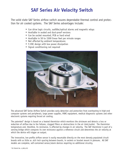
SAF Series Air Velocity SwitchThe solid state SAF Series airflow switch assures dependable thermal control and protec-tion for air cooled systems. The SAF Series advantages include:Can drive logic circuits, audible/optical alarms and magnetic relaysAvailable in sealed and dust-proof versionsCan be socket mounted, PCB or hard wiredAvailable in 50 to 1500 linear feet per minute rangesNot affected by ambient temperatures5 VDC design with low power dissipationSignal conditioning not requiredThe advanced SAF Series Airflow Switch provides early detection and protection from overheating in high-end computer systems and peripherals, large power supplies, HVAC equipment, medical diagnostic systems and other electronic systems requiring forced air cooling.The patented* design is based on a heated thermistor which monitors the airstream and detects a loss or reduction of airflow due to fan failures, clogged filters or obstructions in the air inlet/outlet. The thermistor temperature and, therefore, its resistance, is affected by changes in air velocity. The SAF thermistor is part of a sensing bridge which compares its own resistance against a reference circuit and determines the air velocity at which the device will trigger an output.The innovative, low profile airflow sensor is easily mountable directly on the most densely populated circuit boards with as little as .625 inch spacing between boards, in sockets or bracket mount in plenums. All SAF models are complete, self-contained sensor/alarm devices requiring no additional circuitry.*US Patent No. 4,686,450All SAF Series Sensors are designed to be used in conjunction with typical logic circuitry. Theyoperate on a +5 VDC supply and their output provides an open collector NPN transistor with itsemitter connected to ground (0v). This type of versatile output allows driving logic circuits, indicat-ing incandescent or LED lights or even magnetic relays, from DC sources from 5V to 30V.Mounting Accessories♦Military Socket Assembly with leads, nomounting bracket - P/N 4-1-261♦Bracket only, with leads attached to SAFSensor - P/N 4-1-270♦Socket Assembly with mounting bracketand leads - P/N 4-1-260SPECIFICATIONSInput Voltage: +5 VDC (±5%)Power Dissipation: ½w max Output: open collector, solid state, able to sink up to 100 MA to ground, from DC sources up to 30VSensing range: 50 to 1500 F.P.M.Sensing Tolerance: +10°C to +60°C see ambient temperature compensation curveSensitivity: ±25 F.P.M. from actual settingHysteresis: Series SAF1005 (Stan-dard Model) is typically 10% of the settingIMPROVED AMBIENT TEMPERATURECOMPENSATIONWarren G-V design criteria for the SAF Solid-State Airflow Sensor incorporates ambient temperature compensationtechniques which provide close operating point tolerances over the ambient range of +10° to +60°C. The typical operating point versus ambient temperature curve for 250 FPM is illustrated. Curves for other settings are available.THE SAF SERIESThe Standard Series/SAF1005 - indicates an “alarm condi-tion” on low or no airflow by turning output transistor “on”;output is similar to a closed mechanical contact between output and ground when in alarm condition. A round ver-sion, SAF1006 without a flange is available for less board space utilization.The Fail Safe Series/SAF1025 - an alternative to above-described series, a device failure indicates an “alarm condi-tion” by turning the output “off”; similar to open contacts in alarm condition. It will operate with a wider hysteresis.The Hermetically Sealed Series - withstands all boardwashing methods; more suitable for applications with hostile environments. Sealed versions of all the above units are available.。
FREDFET Power MOS 7 低损耗高电压N型增强模电源MOSFET数据手册说明书

050-7040 R e v D 4-2006MAXIMUM RATINGSAll Ratings: TC = 25°C unless otherwise specified.APT10078BFLL APT10078SFLL1000V14A0.780ΩPower MOS 7®is a new generation of low loss, high voltage, N-Channel enhancement mode power MOSFETS. Both conduction and switchinglosses are addressed with Power MOS 7®by significantly lowering R DS(ON)and Qg . Power MOS 7®combines lower conduction and switching losses along with exceptionally fast switching speeds inherent with APT's patented metal gate structure.Characteristic / Test ConditionsDrain-Source Breakdown Voltage (V GS = 0V, I D = 250µA)Drain-Source On-State Resistance 2 (V GS = 10V, I D = 7A)Zero Gate Voltage Drain Current (V DS = 1000V, V GS = 0V)Zero Gate Voltage Drain Current (V DS = 800V, V GS = 0V, T C = 125°C)Gate-Source Leakage Current (V GS = ±30V, V DS = 0V)Gate Threshold Voltage (V DS = V GS , I D = 1mA)Symbol V DSS I D I DM V GS V GSM P D T J ,T STG T L I AR E AR E ASParameterDrain-Source VoltageContinuous Drain Current @ T C= 25°C Pulsed Drain Current1Gate-Source Voltage Continuous Gate-Source Voltage Transient Total Power Dissipation @ T C = 25°C Linear Derating FactorOperating and Storage Junction Temperature Range Lead Temperature: 0.063" from Case for 10 Sec.Avalanche Current 1 (Repetitive and Non-Repetitive)Repetitive Avalanche Energy 1Single Pulse Avalanche Energy4UNIT Volts AmpsVolts Watts W/°C °C Amps mJSTATIC ELECTRICAL CHARACTERISTICSSymbol BV DSS R DS(on)I DSS I GSS V GS(th)UNIT VoltsOhms µA nA VoltsMINTYPMAX10000.7802501000±10035APT10078BFLL_SFLL10001456±30±404033.23-55 to 15030014301300CAUTION: These Devices are Sensitive to Electrostatic Discharge. Proper Handling Procedures Should Be Followed.APT Website - •Lower Input Capacitance •Increased Power Dissipation •Lower Miller Capacitance •Easier To Drive•Lower Gate Charge, Qg3050-7040 R e v D 4-2006DYNAMIC CHARACTERISTICSAPT10078BFLL_SFLLSOURCE-DRAIN DIODE RATINGS AND CHARACTERISTICSTHERMAL CHARACTERISTICSCharacteristic / Test Conditions Continuous Source Current (Body Diode)Pulsed Source Current 1 (Body Diode)Diode Forward Voltage 2 (V GS = 0V, I S = I D -14A)Peak Diode Recovery dv /dt 5Reverse Recovery Time (I S = I D -14A, di /dt = 100A/µs)Reverse Recovery Charge (I S = I D -14A, di /dt = 100A/µs)Peak Recovery Current (I S = I D -14A, di /dt = 100A/µs)Symbol I S I SM V SDdv /dtt rr Q rr I RRMUNIT Amps Volts V/ns ns µC AmpsMINTYPMAX14561.318T j = 25°C 210T j = 125°C 710T j = 25°C 1.0T j = 125°C 3.6T j = 25°C 9.8T j = 125°C14Symbol R θJC R θJAMINTYPMAX0.3140UNIT °C/WCharacteristic Junction to Case Junction to AmbientSymbol C iss C oss C rss Q g Q gs Q gd t d(on)t r td(off)t f E on E off E on E off Characteristic Input Capacitance Output CapacitanceReverse Transfer Capacitance Total Gate Charge 3Gate-Source Charge Gate-Drain ("Miller") Charge Turn-on Delay Time Rise TimeTurn-off Delay Time Fall TimeTurn-on Switching Energy 6Turn-off Switching Energy Turn-on Switching Energy 6Turn-off Switching Energy Test ConditionsV GS = 0VV DS = 25V f = 1 MHz V GS = 10VV DD = 500VI D = 14A @ 25°C RESISTIVE SWITCHINGV GS = 15VV DD = 500V I D = 14A @ 25°CR G = 1.6ΩINDUCTIVE SWITCHING @ 25°CV DD = 667V V GS = 15V I D = 14A, R G = 3ΩINDUCTIVE SWITCHING @ 125°CV DD = 667V V GS = 15V I D = 14A, R G = 3ΩMIN TYP MAX 252543075951260983093557574095UNIT pFnCnsµJ1Repetitive Rating: Pulse width limited by maximum junction temperature2Pulse Test: Pulse width < 380 µs, Duty Cycle < 2%3See MIL-STD-750 Method 34714Starting T j = +25°C, L = 13.27mH, R G = 25Ω, Peak I L = 14A5dv /dt numbers reflect the limitations of the test circuit rather than the device itself. I S ≤ I D -14A di /dt ≤ 700A/µsV R ≤ 1000T J ≤ 150°C 6 Eon includes diode reverse recovery. See figures 18, 20.APT Reserves the right to change, without notice, the specifications and inforation contained herein.Z θJ C , T H E R M A L I M P E D A N C E (°C /W )RECTANGULAR PULSE DURATION (SECONDS)FIGURE 1, MAXIMUM EFFECTIVE TRANSIENT THERMAL IMPEDANCE, JUNCTION-TO-CASE vs PULSE DURATION0.350.300.250.200.150.100.050050-7040 R e v D 4-2006APT10078BFLL_SFLLTypical Performance CurvesR D S (O N ), D R A I N -T O -S O U R C E O N R E S I S T A N C E I D , D R A I N C U R R E N T (A M P E R E S )I D , D R A I N C U R R E N T (A M P E R E S )(N O R M A L I Z E D )V G S (T H ), T H R E S H O L D V O L T A G E B V D S S , D R A I N -T O -S O U R C E B R E A K D O W N R D S (O N ), D R A I N -T O -S O U R C E O N R E S I S T A N C EI D , D R A I N C U R R E N T (A M P E R E S )(N O R M A L I Z E D )V O L T A G E (N O R M A L I Z E D )V DS , DRAIN-TO-SOURCE VOLTAGE (VOLTS)FIGURE 2, TRANSIENT THERMAL IMPEDANCE MODELFIGURE 3, LOW VOLTAGE OUTPUT CHARACTERISTICS V GS , GATE-TO-SOURCE VOLTAGE (VOLTS)I D , DRAIN CURRENT (AMPERES)FIGURE 4, TRANSFER CHARACTERISTICSFIGURE 5, R DS (ON) vs DRAIN CURRENTT C , CASE TEMPERATURE (°C)T J , JUNCTION TEMPERATURE (°C)FIGURE 6, MAXIMUM DRAIN CURRENT vs CASE TEMPERATURE FIGURE 7, BREAKDOWN VOLTAGE vs TEMPERATURE T J , JUNCTION TEMPERATURE (°C)T C , CASE TEMPERATURE (°C)FIGURE 8, ON-RESISTANCE vs. TEMPERATURE FIGURE 9, THRESHOLD VOLTAGE vs TEMPERATURE0.00295F0.0114F0.174FJunction temp. (°C)RC MODELCase temperature. (°050-7040 R e v D 4-2006V DS , DRAIN-TO-SOURCE VOLTAGE (VOLTS)V DS , DRAIN-TO-SOURCE VOLTAGE (VOLTS)FIGURE 10, MAXIMUM SAFE OPERATING AREAFIGURE 11, CAPACITANCE vs DRAIN-TO-SOURCE VOLTAGEQ g , TOTAL GATE CHARGE (nC)V SD , SOURCE-TO-DRAIN VOLTAGE (VOLTS)FIGURE 12, GATE CHARGES vs GATE-TO-SOURCE VOLTAGEFIGURE 13, SOURCE-DRAIN DIODE FORWARD VOLTAGEV G S , G A T E-T O -S O U R C E V O L T A G E (V O L T S )I D, D R A I N C U R R E N T (A M P E R E S )I D R , R E V E R S E D R A I N C U R R E N T(A M P E R E S )C , C A P A C I T A N C E (p F )I D (A)I D (A)FIGURE 14, DELAY TIMES vs CURRENTFIGURE 15, RISE AND FALL TIMES vs CURRENT I D (A)R G , GATE RESISTANCE (Ohms)FIGURE 16, SWITCHING ENERGY vs CURRENTFIGURE 17, SWITCHING ENERGY VS. GATE RESISTANCES W I T C H I N G E N E R G Y (µJ )t d (o n ) a n d t d (o f f ) (n s )S W I T C H I N G E N E R G Y (µJ )t r a n d t f (n s )050-7040 R e v D 4-2006APT10078BFLL_SFLLAPT’s products are covered by one or more of U.S.patents 4,895,810 5,045,903 5,089,434 5,182,234 5,019,5225,262,336 6,503,786 5,256,583 4,748,103 5,283,202 5,231,474 5,434,095 5,528,058 and foreign patents. US and Foreign patents pending. All Rights Reserved.Dimensions in Millimeters and (Inches)TO -247 Package OutlineDimensions in Millimeters (Inches)and Leads are PlatedD 3PAK Package OutlineFigure 18, Turn-on Switching Waveforms and Definitions Figure 19, Turn-off Switching Waveforms and DefinitionsI C APT15DF100V CEV DD GSwitching EnergyDrain CurrentDrain VoltageGate VoltageT J125°C 10%0t d(off)90%t f90%Drain CurrentDrain VoltageGate VoltageT J 125°CSwitching Energy10%t d(on)90%5%t r5%10%。
双金属自润滑轴承资料
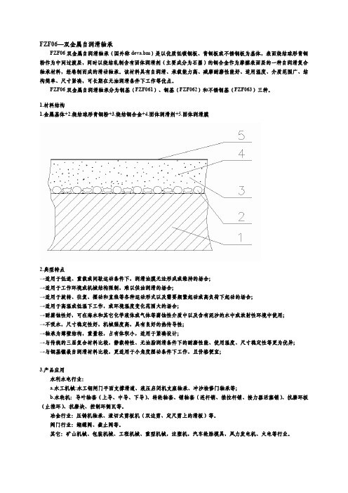
28+0.056 +0.035
1.5-0.010 -0.035
0.5
1.0
0.8
26
29
29+00.021
26-0.065 -0.086
26-0.040 -0.061
29+0.049 +0.028
29+0.056 +0.035
1.5-0.010 -0.035
0.5
1.0
0.8
28
31
31+00.025
数值 280~320* 110~150* 0.3~1.0* 1.0~1.3* +280~350*
-150 0.10~0.18* 0.10~0.14 0.08~0.11
>40 17.5 13
数值 Ra0.8~1.6
≤ Ra3.2 ≥220 ≥180 r7 s7
H8 或 H9 d7 e7 H7
FZF06 直形轴套尺寸表
1.5-0.010 -0.035
0.5
1.0
0.8
32
36
36+00.025
32-0.080 -0.105
32-0.050 -0.075
36+0.059 +0.034
36+0.068 +0.043
2-0.01 -0.04
0.75 1.5
0.8
34
38
38+00.025
34-0.080 -0.105
34-0.050 -0.075
45-0.050 -0.075
49+0.059 +0.034
49+0.068 +0.043
半柔线材知识基础
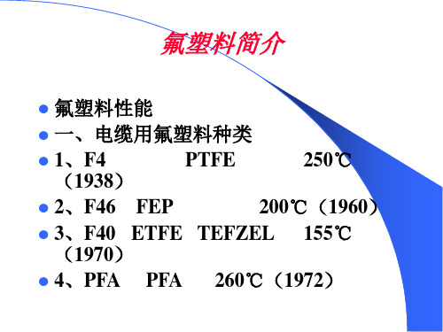
聚四氟乙烯绝缘同轴射频电缆(柔软) 聚四氟乙烯绝缘同轴射频电缆(柔软) SFF系列电缆结构: 系列电缆结构: 系列电缆结构
FEP护套
镀银铜 实芯PTFE绝缘 线编织
内导体
聚四氟乙烯绝缘同轴射频电缆(柔软) 聚四氟乙烯绝缘同轴射频电缆(柔软)
型号
SFF
标准
SJ1563 SJ1563
规格范围
5050SFF 50-1 ~50-9
PTFE糊状挤出关键工序的控制 糊状挤出关键工序的控制
②预成型:保证材料不受损伤
①混料:严格的环境控制和科学 工艺配方
④干燥和烧结 干燥温度: 烧结温度: ③挤出成型: 精确的温度控制 世界一留的设备
熔融氟树脂电线成形
真空泵
计米器 放线机 预热器 张力控制台 挤出机 收卷机
设置在张力控制台后,是绕卷 制出的包覆电线的装置。 必须使用在高速成形中可以自 动交替切换的2连式绕卷装置。
内导体
相应国外产品SM86、SM141 、 相应国外产品
工装设备
产品
产品性能
阻抗
衰减、驻 衰减、驻波比
PTFE成型特点和电线 PTFE成型特点和电线
压延 糊状挤出
延伸
绕包
热压着
烧结
Байду номын сангаас
绕包
烧结
烧结
种类 要求特性 低介电常数 低介电损耗 低比重
绕包电线 带子有强度 烧结时无开裂
扁平线 烧成性 透明性 收缩均匀 电气性能良好 多用于计算机 领域 异物管理困难
SFT系列电缆结构: 系列电缆结构: 系列电缆结构
T — 50 —
— 1
铜管外导体
实芯PTFE绝缘
绝缘外径 特性阻抗 内导体
Sfere100说明书中文
模块化多功能电力仪表用户手册本手册适用于以下型号的产品S fere100江 苏 斯 菲 尔 电 气 股 份 有 限 公 司JIANGSU SFERE ELECTRIC CO.,LTD感谢您选择江苏斯菲尔电气股份有限公司研发的模块化多功能电力仪表Sfere100,为了方便您选购和安全、正确、高效的使用本仪表,请仔细阅读本说明书并在使用时务必注意以下几点。
注意CAUTION:该装置必须有专业人员进行安装与检修在对该装置进行任何内部或外部操作前必须切断输入信号和电源始终使用合适的电压检测装置来确定仪表各部位无电压提供给该装置的电参数需在额定范围内下述情况会导致装置损坏或装置工作的异常:辅助电源电压超范围配电系统频率超范围电流或电压输入极性不正确带电拔插通信插头未按要求连接端子连线本手册可以在本公司的主页上下载到最新版本,同时也提供一些相应的测试软件下载。
如果您需要纸质用户手册可以向本公司的技术服务部门申请。
目 录一、产品简介 (1)1.1符合标准 (1)1.2 产品概述 (1)二、技术参数 (1)三、安装与接线 (5)3.1 尺寸图 (5)3.2安装方式 (5)3.3 典型信号接线图 (5)3.4典型功能接线示意图 (7)四、菜单显示与编程 (8)4.1面板说明与使用 (8)4.2菜单介绍与操作 (8)4.3编程操作方法 (23)5.1通讯 (28)5.2电能脉冲输出 (34)5.3开关量输入 (35)5.4继电器输出 (35)5.5模拟量输出 (39)六、常见问题及解决办法 (42)6.1关于通讯 (42)6.2关于电流U I P 等测量不准确 (43)6.3关于电能走字不准确 (43)6.4仪表不亮 (43)6.5仪表不响应任何操作 (43)6.6其它异常情况 (43)一、产品简介1.1符合标准IEC 61557-12:2007 交流1000V和直流1500V以下低压配电系统电气安全防护措施的实验、测量或监控设备第12部分性能测量和监控装置(PMD)IEC 62053-22:2003 电量测量设备(交流)-特殊要求-第22部分:静态电度表(0.5S)IEC 62053-23:2003 电量测量设备(交流)-特殊要求-第23部分:静态无功表(2级)IEC 61010-1:2001 测量、控制以及实验室用电气设备的安全要求-第1部分:一般要求IEC 61000-4-2 电磁兼容性静电放电抗扰度试验IEC 61000-4-3 电磁兼容性射频电磁场辐射抗扰度试验IEC 61000-4-4 电磁兼容性电快速瞬变脉冲群抗扰度试验IEC 61000-4-5 电磁兼容性浪涌(冲击)抗扰度试验IEC 61000-4-6 电磁兼容性射频场感应的传导骚扰抗扰度试验IEC 61000-4-8 电磁兼容性工频磁场抗扰度试验IEC 61000-4-11 电磁兼容性电压暂降、短时中断和电压变化的抗扰度试验IEC 61000-2-6 电磁兼容性无线电干扰IEC 60068-2-30 环境测试工业环境抗扰度1.2 产品概述模块化多功能电力仪表Sfere100可测量各种常用电力参数、有功电能、无功电能、总谐波含量,并具有数字通讯、越限报警、监测开关状态、电能脉冲输出和模拟量输出等功能。
技术说明书 茎流传感器 - SF100,SF200,SF300
技术说明书 茎流传感器 - SF100,SF200,SF300产品介绍由格林斯潘和澳大利亚英联邦科学与工业研究组织(CSIRO),联合研制开发的SF 系列茎流传感器,采用先进的热脉冲技术,可以精确、可靠的监测树木水分利用状况,为农业研究人员、园艺和林业管理人员提供简单、低价位的树木水分自动监测系统。
传感器包括以下型号:SF-100,SF-200,SF-300主要特点SF 系列传感器采用先进的热脉冲监测技术来测定树木茎流。
实践证明,采用热脉冲技术监测树枝和树干的茎流比其它系统采用的热平衡方式更加可靠和精确。
系统小巧、轻便,便于携带和安装,可以在一棵树上安装多个传感器。
有多种微型的或标准的传感器供选择。
智能化的数据采集器接口软件(SAPCOM),提供实时的、完整的茎流输出和数据采集参数控制。
可视化的系统设置图形曲线监测模式。
系统具有自校定功能,确保使用的简单性;在特定的恶劣的工作环境下提供精确、可重复的茎流记录。
在最恶劣的环境下,系统可以长期可靠的使用,并将维护工作降到最低。
基于WINDOWS 操作系统的SAPCAL 软件,提供完备的数据分析和处理功能。
技术原理越来越多的植物学家认识到利用传统的叶片换算法很难解决有关树木和树冠水分利用状况的问题。
尤其是以树为单位监测水分利用状况的全过程。
格林斯潘茎流传感器利用先进的热脉冲技术可以精确、可靠的监测树木的水分利用情况,而且结构坚固、便于携带。
热脉冲或者叫补偿方法被誉为“最准确的流速监测技术”(Zimmerman 1983)在1928年被Rein 用来监测动物体内血液的流速,后来在1932年被Huber 用来监测树木木质部分的水流速度。
木质部分茎流速度的测定,通过向树木导管注入一个小的热脉冲源,然后测量这个脉冲源沿树木导管上升的比率来获得植物木质部分的茎流速率(也称为茎流密度),茎流量等于茎流速率乘以树木导管的截面积。
在确定一棵典型的监测树木后,要确定树心和形成层的边界,探针要保证插入足够的深度,确保热敏电阻位于茎流截面内。
宝诚空气源热泵主要部件及规格

22A
额定水温
55℃
最高水温
70℃
额定电压/频率
380V3N/50Hz
主机质量
300KG
外型尺寸
长
1445mm
宽
710mm
高
1140mm
主机接管尺寸
DN40
自来水压力
≤0.6MPa
接地要求
≤0.1Ω
环境温度
-5~45℃
噪声
≤60dB(A)
以上表格中所列数据是在干球温度20℃,湿球温度15℃,出水温度55℃的环境条件下测得.因科技进步,本公司产品将不断改良、更新,以上参数如有更改,恕不另行通知,数据以产品铭牌为准
宝诚空气源热泵主要部件及规格
A、热水机组
1、压缩机:美国谷轮热泵专用压缩机
2、电子膨胀阀:日本鹭宫
B、空诚空气源热水机组参数
产品名称
商用热泵热水器BCR-10P
所属类别
商用系列
商用型热泵热水器机组技术性能参数
特点说明
产品型号
BCR-10P
额定制热水量Biblioteka 850L/H额定输入功率
9.0KW
额定输入电流
11A
SF1004G中文资料

80
0.3 0.1
70 60 50
.03 .01 .4 20 50 100 200 500
SF
SF
10
01
06
G
4G 00 F1 ~S 8G G 00 01 F1 10 ~S SF 5G 00
1 SF
Tj=25oC Pulse Width=300 s 1% Duty Cycle
.6
.8
Байду номын сангаас1.0
1.2
1.4
元器件交易网
SF1001G THRU SF1008G
10.0 AMPS. Glass Passivated Super Fast Rectifiers
Voltage Range 50 to 600 Volts Current 10.0 Amperes
Features
Low forward voltage drop High current capability High reliability High surge current capability
~S
1
2
5
10
20
50
100
F1
00
30 10
G
4G
10
NUMBER OF CYCLES AT 60Hz
FIG.5- TYPICAL JUNCTION CAPACITANCE PER LEG
M-FAST SFP-SM LC 100Mbps 单模光纤传输器说明书

MTBF (Telecordia SR-332 Issue 3) @ 25°C: 652 Years
Operating temperature:
0-+60 °C
Storage/transport temperature:
-40-+85 °C
Relative humidity (non-condensing):
Operating Voltage: Power consumption:
power supply via the switch 1W
Software
Diagnostics:
Optical input and output power, transceiver temperature
Ambient conditions
Technical Specifications
Product description
Type: Description: Part Number: Port type and quantity:
M-FAST SFP-SM/LC SFP Fiberoptic Fast-Ethernet Transceiver SM 9nector
Scope of delivery:
SFP module
Variants
Item #
Type
943866001 M-FAST SFP-SM/LC
Update and Revision:
Revision Number: 0.55 Revision Date: 08-07-2020
© 2020 Belden, Inc
Network size - length of cable
SFGP 系列轨装式隔离器、配电器 说明书
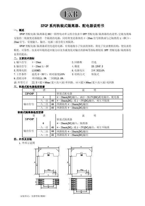
SFGP 系列轨装式隔离器、配电器说明书一、概述SFGP 型配电器/隔离器是DDZ—Ⅲ型电动单元组合仪表中DFP 型配电器/隔离器的改进型,它能为现场安装的二线制变送器提供一个隔离的电源,同时将变送器来的4~20mA 信号转换成与之隔离的1~5V/4~20mA 信号,实现输入、输出、电源三部分的互相隔离。
SFGP 型配电器/隔离器采用先进的电路,有效地缩小了仪表的体积,简化了仪表整机结构,使仪表的精度、可靠性、仪表对环境的适应能力以及负载变化对输出的影响等指标都较原DFP 型配电器/隔离器有显著的提高。
二、主要技术指标 1.输入信号 4~20mA2.回路数任选3.输出信号 4~20mA/1~5V4.精度±0.25%F.S5.绝缘电阻 ≥100M Ω6.电源电压24V.DC ±10% 7.工作条件 温度0~50℃;相对湿度≤85% 8.结构方式 轨装式9.消耗功率 单回路≤1.5W;二回路≤3.0W; 10.外型尺寸 22.5×82×99mm(宽×高×深)单回路、44×82×99mm(宽×高×深)双回路三、轨装式配电器选型型谱型 谱 说 明SFGP 轨装式配电器 44~20mA(DC)输入,18.5~28.5V(DC)配电输出,配电器 一入一出60 4~20mA(DC) 或1~5V(DC)输出,相互不隔离 一入二出66 两路隔离4~20mA(DC)输出 输出信号 二入二出 68 两路隔离4~20mA(DC)输出轨装式隔离器选型型谱型 谱 说 明SFGP 轨装式隔离器64~20mA(DC)输入,隔离器一入一出60 4~20mA(DC) 或1~5V(DC)输出,相互不隔离 一入二出 66 两路隔离4~20mA(DC)输出 输出信号二入二出68 两路隔离4~20mA(DC)输出四、外形及安装 1. 外形示意图安装形式:支撑型轨TS35五、SFGP轨装式配电器/隔离器接线图:SFGP466配电器一入二出SFGP468配电器二入二出SFGP666隔离器一入二出SFGP668隔离器二入二出SFGP660隔离器一入一出(只需要电压输出时,将电流输出端子短路;电压电流同时输出时接线如图)六、接线方法1. 接250Ω的负载时,下面短路的地方不要短路,接500欧的负载时,下面短路的地方要短路。
FL11006环保冷却器数据表说明书

FL11006 Recirculating CoolerRecirculating Cooler/Chiller for environmentally friendly coolingThe FL series offers a new generation of chillers for routine coolingapplications within the laboratory and industry. The temperature stability ofthe PID control is ±0.5°C. All units can easily be cleaned and are providedwith a splash water proof keypad with LED temperature indication. On thefront of the units there is an RS232 interface as well as an alarm shutdown.The filling port is easily accessible placed on the top under a lift-up cover.Another hinged tray serves as a file for the operating manual or otherdocuments concerning the installation. The removable venting grid allows aneasy cleaning of the condenser, the drain tap is easily accessible behind thegrid. All models include an easily visible level indication. Another advantageis the venting slots are on the front and rear and therefore the units can beplaced directly one beside the other (space saving).Your advantagesErgonomic design and easy operationSplash-proof keypadLarge, bright LED displayReliable Microprocessor PID temperature controlFilling level indicatorPowerful immersion pumps, suitable for continuous operationPermissible temperature in return line +80°CEasy filling from the top with hinged protective lidLow liquid level protection with optical and audible alarm signalIntegrated stainless steel bath tanksRemovable venting grid for cleaning of the condenserFront drainNo side ventsRS232 interface for PC-connectionIP class according to IEC 60529: 21Alarm output, potential-free change-over contact (max. 30 VA)Pressure IndicatorBy-pass valve to adjust pump pressureTechnical DataOrder No.9666110Model series FL SeriesCategory Recirculating Coolers Working temperature range (°C)-20 ... +40Temperature stability (°C)±0.5Setting / display resolution0.1 °CTemperature Display LEDCooling capacity (Medium Ethanol)°C200-10-20kW117.553 Pump capacity flow rate (l/min)60Pump capacity flow pressure (psi)7.25...87.02Pump connectionsG1 1/4"Barbed fittings diameter (inner dia. / mm)1"Filling volume liters 39 ... 47Refrigerant stage 1R452A Filling volume refrigerant stage 1 (g)3100Global Warming Potential for 2140Carbon dioxide equivalent stage 1 (t) 6.634Digital interface RS232Optional: Profibus Ambient temperature 5...40 °CDimensions W x L x H (inch)30.7 x 33.5 x 58.3Weight (LBS)547Sound pressure level (distance 1 m) max. (dBA)74Included with each unit 2 barbed fittings for tubing1" l.W. (pump connections with G1 1/4" male)Cooling of compressor AirPower requirement V / Hz / A 3x 230/60/27Available voltage versions400 V / 3 Ph. / 50 Hz 230 V / 3 Ph. / 60 HzSuitable fluids: water, water-glycol mixture, JULABO Thermal bath fluids.Kältemittelangaben gelten für die 50 Hz-Version.CharacteristicsDisplayEasy to readLarge LED temperature display for actual value and setpoint (resolution 0.1 °C)OperationSimple and fastConvenient 3-key setpoint adjustment (FL models)Temperature ControlPrecisePID Temperature control with set control parameters,temperature stability ±0.02...±0.2 °CRefrigeration TechnologyConsistent cooling capacity Easily removable venting grid for quick and easy cleaningTechnical FeaturesSerial connection RS232 interface for PC connection, e.g. for datacommunication and recording of measured valuesRefer to for more information regarding the entire JULABO product portfolio.Technical changes without prior notification. Images may deviate from the original.。
astm f 1960加固环尺寸 -回复

astm f 1960加固环尺寸-回复ASTM F1960加固环尺寸,对于管道连接和加固非常重要。
在本文中,我们将一步一步回答有关ASTM F1960加固环尺寸的问题,以帮助读者更好地了解这项技术。
第一步:什么是ASTM F1960加固环?ASTM F1960加固环是一种用于连接管道的密封材料。
它由聚苯乙烯(PEX)材料制成,具有优异的耐化学品和耐冲击性能。
加固环通常用于冷热水管道系统、供暖系统以及一些特殊需求的管道连接。
第二步:ASTM F1960加固环的尺寸有哪些?ASTM F1960加固环有不同的尺寸,以适应不同直径的管道。
一般来说,其尺寸范围从3/8英寸到3/4英寸不等,具体可根据需要进行选择。
下面是ASTM F1960加固环常见的尺寸:1. 3/8英寸加固环:适用于3/8英寸直径的管道连接。
2. 1/2英寸加固环:适用于1/2英寸直径的管道连接。
3. 5/8英寸加固环:适用于5/8英寸直径的管道连接。
4. 3/4英寸加固环:适用于3/4英寸直径的管道连接。
需要注意的是,这些尺寸只是常见的规格,实际上还有其他尺寸可供选择。
在选择加固环尺寸时,需要根据实际需求和管道直径来确定。
第三步:如何选择适合的ASTM F1960加固环尺寸?选择适合的ASTM F1960加固环尺寸时,需要考虑以下几个因素:1. 管道直径:首先需要确定管道的直径,然后选择与之匹配的加固环尺寸。
加固环应能完全覆盖管道的连接点,确保连接的密封性能。
2. 管道材质:管道的材质也是选择加固环尺寸的重要因素。
不同的管道材质可能有不同的直径标准,因此需要根据管道材质来选择合适的加固环尺寸。
3. 工程要求:还需要考虑工程要求和环境条件。
如果需要耐高温或耐腐蚀性能,可能需要选择特殊材质或特殊规格的加固环尺寸。
在选择加固环尺寸时,建议咨询专业工程师或供应商的意见,以确保选择合适的尺寸来满足实际需求。
第四步:ASTM F1960加固环的安装方法?安装ASTM F1960加固环的方法如下:1. 准备工作:首先需要准备好所需的工具和材料,包括管道切割工具、加固环、加固环安装工具、加固环套管等。
- 1、下载文档前请自行甄别文档内容的完整性,平台不提供额外的编辑、内容补充、找答案等附加服务。
- 2、"仅部分预览"的文档,不可在线预览部分如存在完整性等问题,可反馈申请退款(可完整预览的文档不适用该条件!)。
- 3、如文档侵犯您的权益,请联系客服反馈,我们会尽快为您处理(人工客服工作时间:9:00-18:30)。
- 274 -
元器件交易网
RATINGS AND CHARACTERISTIC CURVES (SFF1001G THRU SFF1008G)
FIG.1- REVERSE RECOVERY TIME CHARACTERISTIC AND TEST CIRCUIT DIAGRAM
NUMBER OF CYCLES AT 60Hz
10
01 SF F1 0
~S FF 10 G
FF 5G ~S SF F1 00 10
0 1
30பைடு நூலகம்
04 G
2
5
10
20
50
100
FIG.5- TYPICAL JUNCTION CAPACITANCE PER LEG
100
Tj=25 0C
3 1
90
G 08 10 FF ~S 7G 00 F1 SF
. 2 72 ( 6 .9 ) . 2 48 ( 6 .3 )
Mechanical Data
Case: ITO-220AB molded plastic Epoxy: UL 94V-O rate flame retardant Terminals: Leads solderable per MIL-STD202, Method 208 guaranteed Polarity: As marked High temperature soldering guaranteed: 260oC/10 seconds.16”,(4.06mm) from case. Weight: 2.24 grams Mounting torque: 5 in – 1bs. max.
. 6 06 (1 5. 5) . 5 83 (1 4. 8)
. 11 0 (2 .8 ) .09 8 ( 2 . 5 )
. 5 43 (1 3. 8) . 5 12 (1 3. 2)
PIN 1 PIN 3 PIN 2 Positive CT
Dimensions in inches and (millimeters)
200 140 200
300 210 300
400 280 400
500 350 500
600 420 600
10.0 125 0.975 10.0 400 35 70 50 1.3 1.7
V uA uA nS pF ℃/W ℃ ℃
2.0 Operating Temperature Range -65 to +150 Storage Temperature Range TSTG -65 to +150 Notes: 1. Reverse Recovery Test Conditions: IF=0.5A, IR=1.0A, IRR=0.25A 2. Measured at 1 MHz and Applied Reverse Voltage of 4.0 V D.C. 3. Mounted on Heatsink Size of 2 in x 3 in x 0.25 in Al-plate.
Maximum Recurrent Peak Reverse Voltage Maximum RMS Voltage Maximum DC Blocking Voltage Maximum Average Forward Rectified Current .375 (9.5mm) Lead Length @TC = 100℃ Peak Forward Surge Current, 8.3 ms Single Half Sine-wave Superimposed on Rated Load (JEDEC method ) Maximum Instantaneous Forward Voltage @ 5.0A Maximum DC Reverse Current @ TA=25℃ at Rated DC Blocking Voltage @ TA=100℃ Maximum Reverse Recovery Time (Note 1) Typical Junction Capacitance (Note 2) Typical Thermal Resistance (Note 3)
SF
1 2
1.2
1.4
1.6
1.8
5
10
20
50
100
200
500
1000
REVERSE VOLTAGE. (V)
FORWARD VOLTAGE. (V)
- 275 -
SFF SFF SFF SFF 1001G 1002G 1003G 1004G 1005G 1006G 1007G 1008G
Units V V V A A
VRRM VRMS VDC I(AV) IFSM VF IR Trr Cj RθJC TJ
50 35 50
100 70 100
150 105 150
Maximum Ratings and Electrical Characteristics
Rating at 25℃ambient temperature unless otherwise specified. Single phase, half wave, 60 Hz, resistive or inductive load. For capacitive load, derate current by 20% Symbol SFF SFF SFF SFF Type Number
NOTES: 1. Rise Time=7ns max. Input Impedance= 1 megohm 22pf 2. Rise Time=10ns max. Sourse Impedance= 50 ohms
-1.0A 1cm SET TIME BASE FOR 5/ 10ns/ cm
FIG.2- MAXIMUM FORWARD CURRENT DERATING CURVE
1
TJ=25 0C
0.1
0
20
40
60
80
100
120
140
90 60 30
PERCENT OF RATED PEAK REVERSE VOLTAGE. (%)
FIG.6- TYPICAL FORWARD CHARACTERISTICS PER LEG
100
INSTANTANEOUS FORWARD CURRENT. (A)
AVERAGE FORWARD CURRENT. (A)
20 16 12 8 4 0
FIG.3- TYPICAL REVERSE CHARACTERISTICS
1000
INSTANTANEOUS REVERSE CURRENT. ( A)
100
TJ=100 0C
10
TJ=75 0C
0
50 CASE TEMPERATURE. ( C)
Features
Low forward voltage drop High current capability High reliability High surge current capability
ITO-220AB
.1 34 (3 .4) D IA .11 3 ( 3 .0 )D I A
.112 (2 .85 ) .10 0 ( 2 .5 5)
50W NONINDUCTIVE 10W NONINDUCTIVE +0.5A (-) DUT (+) 50Vdc (approx) (-) PULSE GENERATOR (NOTE 2) 1W NON INDUCTIVE OSCILLOSCOPE (NOTE 1) (+) 0 -0.25A trr
CAPACITANCE.(pF)
80
0.3 0.1
70 60 50 40
0.03 0.01 0.4 0.6 0.8 1.0
06
Tj=25oC Pulse Width=300 s 1% Duty Cycle
G
G 04 10 FF ~S G 1G 08 00 10 F1 FF SF ~S 5G 00 F1
元器件交易网
SFF1001G THRU SFF1008G
Isolation 10.0 AMPS. Glass Passivated Super Fast Rectifiers
Voltage Range 50 to 600 Volts Current 10.0 Amperes
o
100
150
PEAK FORWARD SURGE CURRENT. (A)
150 120
FIG.4- MAXIMUM NON-REPETITIVE FORWARD SURGE CURRENT PER LEG
TJ=125 0C
8.3ms Single Half Sine Wave JEDEC Method
