梅卡洛说明书
CAMOZZI 2系列手动操作微型阀门说明书
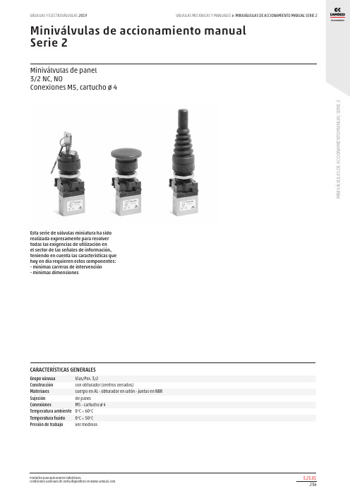
CARACTERÍSTICAS GENERALES
Grupo válvula
Vías/Pos. 3/2
Construcción
con obturador (centros cerrados)
Materiales
cuerpo en AL - obturador en latón - juntas en NBR
Sujeción
de panel
Conexiones
M5 - cartucho ø 4
Temperatura ambiente 0°C ÷ 60°C
Temperatura fluido 0°C ÷ 50°C
Presión de trabajo
ver modelos
Productos para aplicaciones industriales. Condiciones Generales de Venta disponibles en .
C (Suministro/puerto) Ø4/2 M5 Ø4/2 M5
Símbolos VN02 VN02 VN31 VN31
Productos para aplicaciones industriales. Condiciones Generales de Venta disponibles en .
MINIVÁLVULAS DE ACCIONAMIENTO MANUAL SERIE 2
Mod. 234-975 235-975 244-975 245-975
Presión de trabajo (bar) 2÷8 2÷8 2÷8 2÷8
Caudal (Nl/min) 60 60 60 60
Fuerza de accionamiento 7 7 7 7
GIV21AD30 商品说明书

Serie | 6, Congelatore da incasso, 87.4 x 55.8 cmGIV21AD30Accessori specialiKFZ20AX0 :Congelatore con 3 cassetti trasparenti: vioffre molto spazio e una chiara visione -molto economico.SuperCongelamento automatico: Protegge gli alimentisurgelati dallo scongelamento.BigBox cassetto: molto spazio per le confezioni grandi dialimenti congelati.LowFrost per una formazione ridotta di brinaFreshSense: la temperatura perfetta di conservazione.Dati tecniciDisplay temperatura del congelatore : nessunoIlluminazione : noCategoria prodotto : congelatoreDa incasso / a libera installazione : Da incassoPorta pannellabile : ImpossibileSistema No Frost : NoAltezza del prodotto : 874Larghezza del prodotto : 558Profondità del prodotto : 545Dimensioni del prodotto imballato (mm) : 950 x 640 x 620Peso netto (kg) : 40.328Peso lordo (kg) : 43.1Dati nominali collegamento elettrico (W) : 90Corrente (A) : 10Frequenza (Hz) : 50Certificati di omologazione : CE, VDELunghezza del cavo di alimentazione elettrica (cm) : 230Cerniera porta : Reversibile a destraDurata di conservazione in caso di interruzione dell'energiaelettrica (h) : 22Azione di sbrinamento : manualeSegnalazione guasti / Malfunzionamenti : visual and audibleBloccaggio porte : noNumero di cassetti/cestelli : 3Vani congelatore con sportello : 0Codice EAN : 4242002920184Marca : BoschNome prodotto / codice commerciale : GIV21AD30Categoria prodotto : congelatoreConsumo di energia annuale (kWh/annum) - nuovo (2010/30/EC) : 157.00Capacità netta del congelatore (l) - nuovo (2010/30/EC) : 97Capacità di congelamento (kg/24h) - nuovo (2010/30/EC) : 8Classe climatica : SN-TRumorosità (dB(A) re 1 pW) : 36Installazione : Totalmente integrato'!2E20A C-j c a b i e!1/3Serie | 6, Congelatore da incasso, 87.4 x 55.8cmGIV21AD30Congelatore con 3 cassetti trasparenti: vioffre molto spazio e una chiara visione -molto economico.Prestazioni e consumo-Classe di efficienza energetica: A++-Consumo energetico¹ : 157 kWh/anno-Contenuto utile totale: 97 l-Livello sonoro: 36 db(A) re 1 pW-Classe climatica SN-TComfort e sicurezza-FreshSense - con sensori per il controllo delle temperature-Regolazione elettronica della temperatura, leggibile attraversoLED-Allarme acustico, Allarme ottico per aumento dellatemperatura-Interruttore superfreezer: Manual/automatic activiation-Cerniera professionale con SoftCloseVano Congelatore-Capienza netta congelatore **** : 97 l-Capacità di congelamento: 8 kg in 24 ore-Conservazione senza energia elettrica: 22 ore-3 cassetti trasparenti, di cui 1 Big Box-LowFrost - meno ghiaccio e veloce sbrinamentoAccessori-1 x Accumulatore di freddo, Vaschetta per il ghiaccioInformazioni tecniche-Integrabile cerniere piatte-Cerniere a destra, invertibili-Cerniere a destra-Altezza della nicchia (H x B x T): 88.0 cm x 56.0 cm x 55.0 cm-¹In base ai risultati della prova standard di 24 ore,concernante il consumo effettivo dipendente dell'utilizzazione / posizione del dispositivo.2/3Serie | 6, Congelatore da incasso, 87.4 x 55.8cmGIV21AD303/3。
梅卡曼德产品手册说明书

性价比高 I 开放性强 I 部署迅速梅卡曼德产品手册智能程度高 I 稳定性好 I 案例丰富将智能赋予工业机器人视觉引导拆码垛 I 货品拣选 I 快递供包 I 工件上料 I 涂胶 I 定位 I 装配工业级3D 相机Mech-Eye图形化机器视觉软件Mech-Vision 机器人智能编程环境Mech-Viz采用深度学习、3D 视觉、智能路径规划等技术,梅卡曼德为生产制造、物流、电商零售等行业用户,提供从3D 传感器到机器人适配及部署的一整套智能工业机器人解决方案。
可用于搬运(拆码垛)、上料、拣选、分类、定位、涂胶、装配、拧螺丝等场景。
具有性价比高、稳定可靠等特点。
1.智能程度高:基于强大的算法,我们的方案可处理不同物体,亦可应对多种复杂情况。
2.稳定性强:Mech-Eye 工业级3D 相机已通过超10000小时连续运行测试,稳定性好;智能规划路径,避免碰撞等问题。
3.应用案例丰富:方案已部署在十余个国家的数百个客户场景中,其中包括汽车、家电、钢铁、食品等行业的领军企业。
4.性价比高:价格仅为国外典型同类产品二分之一到三分之一。
5.开放性强:产品可适配各种主流品牌的机器人,支持对接各种系统和软件二次开发。
6.部署简单高效:即插即用的解决方案,节省大量部署时间。
完全可视化、无代码的编程界面,大大降低使用难度和部署成本。
方案优势完成复杂条件下的识别、定位、测量等视觉功能获取物体高精度的 3D 信息控制机器人应对复杂的应用全力协助业务伙伴提升竞争力,把握智能机器人时代的先机支持和服务梅卡曼德团队超过300人,可为机器人集成商提供交付支持、人员培训、参考方案设计、展会支持、重难点项目攻关等支持和服务。
Mech-Eye 工业级 3D 相机高性能工业级3D 相机,可对众多类型的物体输出高质量的3D 数据;多种相机型号,满足不同场景中抗环境光、高精度、高速度、小体积等多样化需求。
Mech-Vision图形化机器视觉软件新一代机器视觉软件,完全图形化的界面,无需编写代码即可完成拆垛、无序工件上料、免注册货品抓取、涂胶/喷胶、精确定位、缺陷检测、尺寸测量等先进机器视觉应用;内置3D 视觉、深度学习等前沿算法模块,可满足复杂、多样的实际需求。
Media Matic 磨损机器人 spare parts catalogue说明书
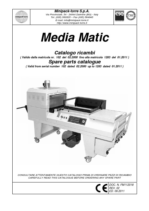
Minipack-torre S.p.A.Via Provinciale, 54 - 24044 Dalmine (BG) - ItalyTel. (035) 563525 – Fax (035) 564945E-mail:**********************http://www.minipack-torre.itMedia MaticCatalogo ricambi( Valido dalla matricola nr. 102 del 02.2000 fino alla matricola 1283 del 01.2011 )Spare parts catalogue( Valid from serial number 102 dated 02.2000 up to 1283 dated 01.2011 )CONSULTARE ATTENTAMENTE QUESTO CATALOGO PRIMA DI ORDINARE PEZZI DI RICAMBIOCAREFULLY READ THIS CATALOGUE BEFORE ORDERING ANY SPARE PARTDOC. N. FM112018 REV. 02 ED. 09.2011INDICE GRUPPI DI RICAMBIO / INDEX OF SPARE PARTS GROUPSTAVOLA SCHEME DESCRIZIONEDESCRIPTIONPAGINAPAGE1 GRUPPO LAMA SALDANTESEALING BLADE GROUP22 GRUPPO TAGLIERINACUTTER GROUP33 GRUPPO SUPPORTO BOBINAFILM ROLL SUPPORT GROUP44 GRUPPO AUTOMAZIONE TAGLIERINACUTTER AUTOMATION GROUP55 GRUPPO NASTRO TRASPORTATORETRANSPORT BELT GROUP66 GRUPPO RAFFREDDAMENTOCOOLING GROUP77 GRUPPO AVVOLGITORE FILMFILM WINDER GROUP88 GRUPPO CARENATURABODYWORK GROUP99 GRUPPO NASTRO TRASPORTATORE TUNNEL (ingresso)CONVEYOR BELT TUNNEL GROUP (inlet side)109.1 GRUPPO NASTRO TRASPORTATORE TUNNEL (uscita)CONVEYOR BELT TUNNEL GROUP (outlet side)119.2 GRUPPO NASTRO TRASPORTATORE TUNNEL (catena)CONVEYOR BELT TUNNEL GROUP (chain)1210 GRUPPO MOTORE + RESISTORIMOTOR + HEATERS GROUP1311 GRUPPO ELETTRICO (pannello comandi)WIRING GROUP (control panel)1411.1 GRUPPO ELETTRICO (cassetto)WIRING GROUP (box)1412 SCHEMA ELETTRICOWIRING DIAGRAM15-1612.1 LEGENDA SCHEMA ELETTRICOWIRING DIAGRAM DESCRIPTION17GRUPPO LAMA SALDANTE SEALING BLADE GROUP TAVOLA 1 SCHEME 1GRUPPO TAGLIERINA CUTTER GROUP TAVOLA 2 SCHEME 2GRUPPO SUPPORTO BOBINA FILM ROLL SUPPORT GROUP TAVOLA 3 SCHEME 3GRUPPO AUTOMAZIONE TAGLIERINA CUTTER AUTOMATION GROUP TAVOLA 4 SCHEME 4GRUPPO NASTRO TRASPORTATORE TRANSPORT BELT GROUP TAVOLA 5 SCHEME 5GRUPPO RAFFREDDAMENTO COOLING GROUP TAVOLA 6 SCHEME 6GRUPPO AVVOLGITORE FILM FILM WINDER GROUP TAVOLA 7 SCHEME 7GRUPPO CARENATURA BODYWORK GROUP TAVOLA 8 SCHEME 8CONVEYOR BELT TUNNEL GROUP (chain) SCHEME 9.2GRUPPO MOTORE + RESISTORI MOTOR + HEATERS GROUP TAVOLA 10 SCHEME 10Valido dalla matr. 200 del 04.2001 e per le matr. 188, 189, 190, 195.Valid from serial number 200 dated 04.2001 and the same for 188, 189, 190, 195.GRUPPO ELETTRICO (pannello comandi)WIRING GROUP (control panel)TAVOLA 11 SCHEME 11POS. POS.CODICI PARTICOLARI ITEMS CODE DENOMINAZIONI PARTICOLARIITEMS DESCRIPTIONQ.tà Q.ty1 S0190056 Pannello + scheda elettronica / Panel + electronic board 1 1.1 FE120363 Scheda elettronica / Electronic board 12 FE080001 Commutatore / Switch1 3 FE340005 Pulsante di emergenza / Emergency pushbutton 1 4 FE340001 Pulsante di marcia / Start button 1 5 FE085004Selettore manuale / Manual selector1GRUPPO ELETTRICO (cassetto)WIRING GROUP (box)TAVOLA 11.1SCHEME 11.1POS. POS. CODICI PARTICOLARI ITEMS CODE DENOMINAZIONI PARTICOLARIITEMS DESCRIPTIONQ.tàQ.tyF1 FE290405 FE290407 FE290408 Fusibile 10.3X38 AM 10A (380/415V) / Fuse 10.3X38 AM 10A (380/415V)Fusibile 10.3X38 AM 16A (230V) / Fuse 10.3X38 AM 16A (230V) Fusibile 10.3X38 AM 20A (200/208V) / Fuse 10.3X38 AM 20A (200/208V)3 F2 FE290401 Fusibile 10.3X38 AM 2A / Fuse 10.3X38 AM 2A 3 F3 FE290401 Fusibile 10.3X38 AM 2A / Fuse 10.3X38 AM 2A 1 F4 FE290121 Fusibile 5X20 T 2A / Fuse 5X20 T 2A 1 KM1 FE110615 Contattore LC1-D18B7 / Contactor LC1-D18B7 1 KM2 FE110602 FE110615 Contattore LC1-D09B7 (380/415V) / Contactor LC1-D09B7 (380/415V)Contattore LC1-D18B7 (200/208/230V) / Contactor LC1-D18B7 (200/208/230V)1 KM3 FE110602 Contattore LC1-D09B7 / Contactor LC1-D09B7 1 KM4 FE110602 Contattore LC1-D09B7 / Contactor LC1-D09B7 1 KM5 FE110602 Contattore LC1-D09B7 / Contactor LC1-D09B7 1 KM6 FE110602 Contattore LC1-D09B7 / Contactor LC1-D09B7 1 KM7 FE370006 Relè 24VAC / Relay 24VAC 1 K1 FE120353 Modulo di potenza / Electronic control board 1 TS1 KR170001 Inverter / Inverter 1 T1 FE440613 FE440612 Trasformatore 2400VA (380/415V) / Transformer 2400VA (380/415V)Trasformatore 2400VA (200/208/230V) / Transformer 2400VA (200/208/230V)1 T2 FE440026 FE440025 Trasformatore 400VA (380/415V) / Transformer 400VA (380/415V)Trasformatore 400VA (200/208/230V) / Transformer 400VA (200/208/230V) 1LEGENDA SCHEMA ELETTRICO WIRING DIAGRAM DESCRIPTION TAVOLA 12.1 SCHEME 12.1Q1 Interruttoregenerale Q1MainswitchF1 Fusibili lama saldante / resistori 10.3X38 F1 Sealing blade / heaters fuse 10.3X38F2 Fusibili motore ventola / nastro / telaio 10.3X38 F2 Fan / belt / frame motor fuse 10.3X38F3 Fusibile trasformatore ausiliario 10.3X38 F3 Auxiliary transformer fuse 10.3X38F4 Fusibile motori ventilatore / pompa 5X20 F4 Ventilator / pump motor fuse 5X20FU Fusibile scheda 5X20 FU Board fuse 5X20EH1 Resistenza di taglio EH1 Cutting resistanceEH2 Resistori forno EH2 HeaterEH3 Resistori forno EH3 HeaterEH4 Resistori forno EH4 HeaterM1 Motore ventola M1 Fan motorM2 Motore nastro saldatura M2 Belt motorM3 Motore automazione telaio M3 Frame drive motorM4 Motore nastro forno M4 Belt oven motorM5 Motoreventilatore M5Ventilatormotor M6 Motore pompa M6 Pump motorM7 Motore avvolgitore M7 Winder motorT1 Trasformatore di taglio T1 Cut transformerT2 Trasformatoreausiliario T2 AuxiliarytransformerSQ Finecorsaavvolgitore SQ Winder limit switchSQ1 Finecorsa discesa telaio SQ1 Frame lowering limit switchSQ2 Finecorsa salita telaio SQ2 Frame lifting limit switchSQ3 Finecorsa esclusione sicurezza SQ3 Safety device cutting out limit switchSQ5 Finecorsa sicurezza SQ5 Safety limit switchKM1 Contattore taglio KM1 Cutting contactorKM2 Contattore resistori forno KM2HeaterscontactorKM3 Contattore ventola forno KM3 Fan contactorKM4 Contattore nastro KM4 Sealing belt contactorKM5 Contattore salita telaio KM5 Frame descent contactorKM6 Contattore discesa telaio KM6 Frame rise contactorKM7 Contattore accessori KM7 Accessories contactorSB0 Pulsante di emergenza SB0 Emergency pushbuttonSB1 Pulsante di marcia SB1 Start buttonSA1 Selettore manuale SA1 Manual selectorYA Elettromagnete saldatura YA Sealing magnetSP Pedale (optional) SP Foot pedalBT1 Termocoppia BT1 ThermocoupleK1 Modulo di potenza K1 Electronic control boardSK1 Scheda comando SK1 Control boardTS1 Inverter TS1 InverterVia Provinciale, 54 - 24044 DALMINE (BG) - ITALY Tel. (035) 563525 – Fax (035) 564945E-mail:**********************http://www.minipack-torre.it。
SIMODRAW中文 操作说明书
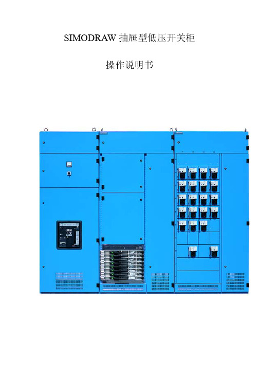
SIMODRAW抽屉型低压开关柜操作说明书注意!对开关柜的任何操作都应预先阅读本说明书。
开关柜的安装和使用必须遵守标准和规范中对于电气产品的柜定,必须遵守本说明书的要求。
开关柜必须安装在适合的室内环境中。
对开关柜的任何操作和维护都应由经过预先培训的专业电气人员进行。
禁止把开关柜置于超出其额定负载的情况下运行。
必须注意开关柜上的任何带电危险标记。
对开关柜的任何违规操作均可能损坏设备,甚至引起严重事故。
应把本手册放在可以方便拿到的地方。
应由专业人员负载电气设备的安全管理。
目录1 总则1.1概述1.2标准和规范1.3使用条件2 开关柜的运行2.1起动前的准备工作2.2起动2.3 开关柜的操作2.3.1 PC柜(框架式断路器)的操作2.3.1.1 框架断路器的移动2.3.1.2 框架式断路器的分合2.3.2 抽屉式开关柜的操作2.3.2.1 A ,B模数抽屉单元的操作2.3.2.2 1~4模数抽屉单元的操作3 维护3.1检查3.2保养1.总则1.1概述本技术条件适用于,SIMODRAW抽屉式低压电气柜装置用于三相交流50/60HZ额定电压至690V的电力系统中作为户内配电、动力集中控制和传动之用。
1.2标准与规范国际电工委员会标准:•IEC60439(1992)《低压成套开关设备和控制设备》中国国家标准:•GB9466-88 《低压成套开关设备基本试验方法》•GB2681-81 《电工成套装置中的导线颜色》•GB2682-81 《电工成套装置中的指示灯和按钮的颜色》•GB4942-2-93 《低压电器外壳防护等级》•JB3084-82 《电力传动控制站的产品包装与运输规程》1.3使用条件•周围空气温度不高于40℃,并且在24小时内平均温度不高于+35℃周围空气温度的下限为-5℃。
•大气条件:空气清洁,相对湿度在最高温度为40℃时不超过50%,在较低温度时允许有较高的相对湿度。
例如+20℃时为90%,但应考虑到由于温度的变化,有可能会偶然地产生适度的凝露。
Omega OS562 红外温度计说明书
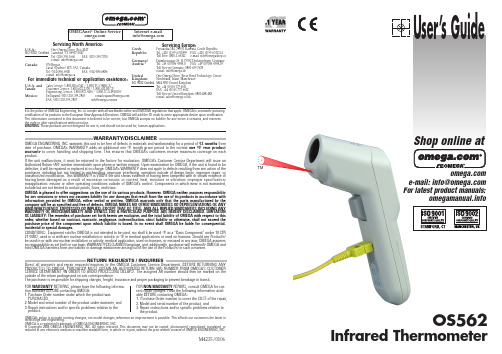
e-mail:**************For latest product manuals:User’s GuideOS562Infrared ThermometerShop online atIt is the policy of OMEGA Engineering, Inc. to comply with all worldwide safety and EMC/EMI regulations that apply. OMEGA is constantly pursuingcertification of its products to the European New Approach Directives. OMEGA will add the CE mark to every appropriate device upon certification.The information contained in this document is believed to be correct, but OMEGA accepts no liability for any errors it contains, and reserves the right to alter specifications without notice.WARNING: These products are not designed for use in, and should not be used for, human applications.WARRANTY/DISCLAIMEROMEGA ENGINEERING, INC. warrants this unit to be free of defects in materials and workmanship for a period of 13 months from date of purchase. OMEGA’s WARRANT Y adds an additional one (1) month grace period to the normal one (1) year product warranty to cover handling and shipping time. T his ensures that OMEGA’s customers receive maximum coverage on each product.If the unit malfunctions, it must be returned to the factory for evaluation. OMEGA’s Customer Service Department will issue an Authorized Return (AR) number immediately upon phone or written request. Upon examination by OMEGA, if the unit is found to be defective, it will be repaired or replaced at no charge. OMEGA’s WARRANTY does not apply to defects resulting from any action of the purchaser, including but not limited to mishandling, improper interfacing, operation outside of design limits, improper repair, or unauthorized modification. This WARRANTY is VOID if the unit shows evidence of having been tampered with or shows evidence of having been damaged as a result of excessive corrosion; or current, heat, moisture or vibration; improper specification;misapplication; misuse or other operating conditions outside of OMEGA’s control. Components in which wear is not warranted,include but are not limited to contact points, fuses, and triacs.OMEGA is pleased to offer suggestions on the use of its various products. However, OMEGA neither assumes responsibility for any omissions or errors nor assumes liability for any damages that result from the use of its products in accordance with information provided by OMEGA, either verbal or written. OMEGA warrants only that the parts manufactured by the company will be as specified and free of defects. OMEGA MAKES NO OTHER WARRANTIES OR REPRESENTATIONS OF ANY KIND WHATSOEVER, EXPRESSED OR IMPLIED, EXCEPT THAT OF TITLE, AND ALL IMPLIED WARRANTIES INCLUDING ANY WARRANTY OF MERCHANTABILITY AND FITNESS FOR A PARTICULAR PURPOSE ARE HEREBY DISCLAIMED. LIMITATION OF LIABILITY : The remedies of purchaser set forth herein are exclusive, and the total liability of OMEGA with respect to this order, whether based on contract, warranty, negligence, indemnification, strict liability or otherwise, shall not exceed the purchase price of the component upon which liability is based. In no event shall OMEGA be liable for consequential,incidental or special damages.CONDITIONS: Equipment sold by OMEGA is not intended to be used, nor shall it be used: (1) as a “Basic Component” under 10 CFR 21 (NRC), used in or with any nuclear installation or activity; or (2) in medical applications or used on humans. Should any Product(s)be used in or with any nuclear installation or activity, medical application, used on humans, or misused in any way, OMEGA assumes no responsibility as set forth in our basic WARRANTY/DISCLAIMER language, and, additionally, purchaser will indemnify OMEGA and hold OMEGA harmless from any liability or damage whatsoever arising out of the use of the Product(s) in such a manner.RETURN REQUESTS /INQUIRIESDirect all warranty and repair requests/inquiries to the OMEGA Customer Service Department. BEFORE RET URNING ANY PRODUCT (S) T O OMEGA, PURCHASER MUST OBTAIN AN AUT HORIZED RET URN (AR) NUMBER FROM OMEGA’S CUST OMER SERVICE DEPART MENT (IN ORDER T O AVOID PROCESSING DELAYS). T he assigned AR number should then be marked on the outside of the return package and on any correspondence.The purchaser is responsible for shipping charges, freight, insurance and proper packaging to prevent breakage in transit. FOR WARRANTY RETURNS, please have the following informa-tion available BEFORE contacting OMEGA:1.Purchase Order number under which the product was PURCHASED,2.Model and serial number of the product under warranty, and3.Repair instructions and/or specific problems relative to the product.FOR NON-WARRANTY REPAIRS,consult OMEGA for cur-rent repair charges. Have the following information avail-able BEFORE contacting OMEGA:1. Purchase Order number to cover the COST of the repair,2.Model and serial number of the product, and3.Repair instructions and/or specific problems relative to the product.OMEGA’s policy is to make running changes, not model changes, whenever an improvement is possible. This affords our customers the latest in technology and engineering.OMEGA is a registered trademark of OMEGA ENGINEERING, INC.© Copyright 2005 OMEGA ENGINEERING, INC. All rights reserved. T his document may not be copied, photocopied, reproduced, translated, or reduced to any electronic medium or machine-readable form, in whole or in part, without the prior written consent of OMEGA ENGINEERING, INC.Servicing North America:U.S.A.:One Omega Drive, Box 4047ISO 9001 Certified Stamford, CT 06907-0047Tel: (203) 359-1660FAX: (203) 359-7700e-mail:**************Canada:976 BergarLaval (Quebec) H7L 5A1, Canada Tel: (514) 856-6928FAX: (514) 856-6886e-mail:*************For immediate technical or application assistance:U.S.A. and Sales Service: 1-800-826-6342 / 1-800-TC-OMEGA Canada:Customer Service: 1-800-622-2378 / 1-800-622-BEST Engineering Service: 1-800-872-9436 / 1-800-USA-WHENMexico:En Espan ˜ol: (001) 203-359-7803e-mail:*****************FAX: (001) 203-359-7807**************.mxServicing Europe:Czech Frystatska 184, 733 01 Karviná, Czech Republic Republic:Tel: +420 (0)59 6311899FAX: +420 (0)59 6311114TollFree:0800-1-66342e-mail:*****************Germany/Daimlerstrasse 26, D-75392 Deckenpfronn, Germany Austria:Tel: +49 (0)7056 9398-0 FAX: +49 (0)7056 9398-29TollFreeinGermany************e-mail:*************United One Omega Drive, River Bend Technology Centre Kingdom:Northbank, Irlam, Manchester ISO 9002 Certified M44 5BD United KingdomTel: +44 (0)161 777 6611FAX: +44 (0)161 777 6622Toll Free in United Kingdom: 0800-488-488e-mail:**************.ukM4235/0106PATENT NOTICE: U.S. P A T . B1 5,368,392; 5,524,984; 5,727,880; 5,823,678; 5,823,679; 6,123,453; 6,267,500 B1; 6,341,891 B1; 6,377,400 B1; 6,540,398 B2; 6,614,830 B1; 6,633,434 B2; 6,659,639; 6,901,089 B1 / Canada 2,114,806; 2,317,734 / France2 756 920; 2 767 921; 2 773 213; 2 773 214 / Germany G 94 22 197.9; G 94 22 203.7 / Holland 1007752 / U.K. Registered 2,237,493;2,320,324; 9726133.3 / EPO 0 644,408 B2; EPO 1085 307 A1. Other U.S. and Foreign Patents Pending.OS562 Thermometer Operating Instructionsne e r c S t l u af e Dwith Lens 79 to display NO I T C N U F y e k y t i v i s s Emissivity key is inset.Need blunt pointed object to use.i m E s s e r P 1.y t i v i s s i m e e h t g n i t t e s r o f y e k y t i v i s s i m E s s e r P 1 y e k p U s s e r p n e h t ,4 y e k n w o D r o 2o t y t i v i s s i m e e h t t e s s s e r p n e h t , y e k e d o M 5.)E 001( 1 o t )E 01( 01.0 m o r f d e g n a h c e b n a c y t i v i s s i m e e h T .t i m r i f n o c o t y e k e d o M s s e r P 5.s w o l l o f s a ns o i t c n u f y a l p s i d e r o m g n i l l o r c s r o f The emissivity data will show here. (The default emissivity is 0.95.)y e k e d o M s s e r P 5e h t r o f d n a X A M n e e w t e b ce n e r e f f i D ,)N I M ( m u m i n i M ,)X A M ( m u m i x a M l l i w g n i d a e r s e d o m l a i c e p s e h t ,t n e m e r u s a e m e h t g n i r u D .s e d o m )G V A ( e g a r e v A d n a )F I D ( N I M .n o c i e d o m e h t e d i s e b d e y a l p s i d e b y e k p U s s e r P 4 y e k n w o D r o 2e h t e g n a h c o t )L A H ( m r a l A h g i H r o )L A L ( m r a l A o L ne h t , y e k .s a e M s s e r p 9 When the reading is 27°C with an LAL of 27.1°C, the :e l p m a x e r o F .t i m r i f n o c o tLow icon will flash and you will hear a beep.t e k c o s e l p u o c o m r e h T h t i w e l p u o c o m r e h t e h t t c e n n o C 01e b o r p e h t t u p d n a y n a your needing to press t u o h t i w y,l l a c i t a m o t u a e r u t a r e p m e t e h t y a l p s i d l l i w r e t e m o m r e h t Thet.e g r a t e h t n o /n i p U e h t n w o d d l o h ,t n e m e r u s a e m e b o r p e h t g n i r u d a t a d m u m i x a m r o m u m i n i m e h t e e s o T .n o t t u b y e k 4y e k n w o D r o 2.After measuring high temps, the probe may remain HOT for while.t i ,e d o m B R P n I ( .e d o m B R P n i s s e l n u ,c e s 06 n a h t e r o m r o f e l d i t f e l f i f f o t u h s y l l a c i t a m o t u a l l i w r e t e m o m r e h t e h T ).s e t u n i m 21 n a h t e r o m r o f e l d i t f e l f i f f o t u h s l l i w This thermometer is a non-contact infrared thermometer. There are many mathematical modes for the infraredfunction. Please remember to keep away from children and don’t use it for safety-related applications.EU L A V D D A y e k p U s s e r P 4 r o f e d o m K C O L .F F O /N O r o f l u f e s u y l r a l u c i t r a p s i e d o m k c o l e h T .s e t u n i m 06 o t p u r o f s e r u t a r e p m e t f o g n i r o t i n o m s u o u n i t n o c ,F I D ,N I M ,X A M n I :e d o m G V Ay e k n w o D s s e r P 29r o f o C r o oswitching.F y e k p U s s e r p d n a 4 r o f n o i t c n u f t h g i l k c a b .F F O /N O t s r i F :s e d o m l l a n I .s a e M e h t down d l o h key y e k n w o D s s e r p d n a 2r o f n o i t c n u f r e s a l .F F O /N O NO I T U A C .1 R E S A L E H T O T N I Y L T C E R I D K O O L T O N O D ,E S U N I S I E C I V E D N E H W BEAM – PERMANENT EYE DAMAGE MAY RESULT..2.R E S A L E H T G N I T A R E P O N E H W N O I T U A C E M E R T X E E S U .3.S E Y E S ʼE N O Y N A D R A W O T E C I V E D E H T T N I O P R E V E N .4.N E R D L I H C L L A F O H C A E R F O T U O P E E K G N I N A E L C & E G A R O T S The thermometer should be stored at room temperature between -20 and 65°C (-4 and 149°F).eb d l u o h s e r a C .s e m i t l l a t a n a e lc t p e k e bd l u o h s s ne l e h T .r e t e m o m r e h t e h tf o t r a p e t a c i l e d t s o m e h t s i s n e l r o s n e s e h T s; use only a soft cloth or cotton swab moistened with water or medical alcohol. Allow then e l e h t g n i n a e l c n e h w n e k a t .r e t e m o m r e h t e h t f o t r a p y n a e g r e m b u s t o n o D .r e t e m o m r e h t e h t g n i s u e r o f e b y r d lens to fully SE G A S S E M R O R R E D C L :s w o l l o f s a s e g a s s e m c i t s o n g a i d l a u s i v s e t a r o p r o c n i r e t e m o m r e h t e h T ʻHiʼ or ʻLoʼ is displayed when the temperature being measured is outside of the settings of HAL and LAL.ʻEr2ʼ is displayed when the thermometer is exposed to rapid changes in the ambient temperature. ʻEr3ʼ is displayed when the ambient temperature exceeds 0°C (32°F) or 50°C (122°F). The thermometer should be allowed plenty of time (minimum 30 minutes)to stablize to the working/room temperature.For all other error messages, it is necessary to reset the thermometer. To reset it, turn the instrument off, remove the batteries and wait for a minimum of one minute, reinsert the batteries and turn the instrument on. If the error message remains, please contact the Customer Service department for further assistance: 1-800-622-2378 or 203-359-1660. We can also be reached on the Internet at and by e-mail:**************SE I R E T T A B :s w o l l o f s a n o i t a c i d n i y r e t t a b w o l l a u s i v s e t a r o p r o c n i r e t e m o m r e h t e h T s t n e m e r u s a e m :ʼK O y r e t t a B ʻel b i s s o p e r a eb o t s d e e n ies need to ber e t t a b :ʼw o L y r e t t a B ʻe l b i s s o p l l i t s e r a s t n e m e r u s a e m ;d e c a l p e r s t n e m e r u s a e m :ʼd e t s u a h x E y r e t t a B ʻe l b i s s o p t o n e r a batteries are low, the batteries should be replaced immediately with AAA, e h t s e t a c i d n i n o c i ʼy r e t t a B w o L ʻ e h t n e h W batteries; otherwise the e h t g n i c a l p e r e r o f e b f f o t n e m u r t s n i e h t n r u t o t t n a t r o p m i s i t I :e t o n e s a e l P .s e i r e t t a b V 5.1.n o i t c n u f l a m y a m r e t e m o m r e h t batteries promptly and keep away from children.d e s u f o e s o p s i D NSO I T A C I F I C E P S n o i t c n u f n a c S d e r a r f n I t c a t n o c -n o N Thermocouple probe Scan function (K type probe not included)me t I e g n a R t n e m e r u s a e M )F °9991 o t 2.38-( C °0041 -64 to )F °221 o t 23( C °05 o t 0-60 to 760°C (-76 to 1400°F)2% reading or 2°C (4°F)at 20 to 26°C (68 to 78°F) ambient±1.0°C (1.8°F)±2% of reading or 2°C (4°F), whichever is greatere g n a R g n i t a r e p O yc a r u c c A )C °52=b m a T ,C °53~51=j b o T (y c a r u c c A ,C °005~33-=j b o T ()C °3±32=b m a T n o i t u l o s e R )C °9.991~9.9-( F °1.0/C °1.0e m i T e s n o p s e R Built-in laser Non-contact temperature measurement with laser circle sighting.)%09( ce s 112:1:t o p S :e c n a t s i D klight.)c a B d n a r e s a L t u o h t i w ,e n i l a k l A ( e s u s u o u n i t n o c 14 hours 18 min. .p y T e f i L y r e t t a B mm (6.9 x 1.53 x 2.8 in)9.17 x 0.93 x 2.571s n o i s n e m i D )s c p 2A A A ( s e i r e t t a b g n i d u l c n i s (6.3 oz)m a r g 971th g i e W 01 s i r o r r e m u m i x a m e h t ,z H M 006 o t 002 m o r f m /V 3 f o d l e i f c i t e n g a m o r t c e l e an r e d n U :e t o N o81( C o.)F Caution: The measure range is for thermometer only. User should choose proper probre types for different kinds of applications. Please make sure the target to be measured will not exceed the temperature range of the probe to avoid permanent damage of the thermocouple probe. IF R /C M E f o h t g n e r t s d l e i f c i t e n g a m o r t c e l e y c n e u q e r f o i d a r n i h t i w d e t a r e p o s i t i n u e h t f i d e t c e f f a e b y a m s g n i d a e R .d e t c e f f a y l t n e n a m r e p e b t o n l l i w t n e m u r t s n i e h t f o e c n a m r o f r e p e h t t u b ,r e t e m r e p s t l o v 3 y l e t a m i x o r p p a ____。
Sigma Aldrich mPAGE Gel Caster用户指南说明书

User Guide mPAGE® Gel Caster GCR2MGCK-75MMGCK-10MMGCK-15MWhat’s inside:Introduction . . . . . . . . . . . . . . . . . . . . . .2 Specifications . . . . . . . . . . . . . . . . . . . . .2 Maintenance ofmPAGE® Glass Plates and Combs . . . . . .3 mPAGE® Gel Caster . . . . . . . . . . . . . . . . .3 ComponentsAssemblyRecommended Volumes Troubleshooting . . . . . . . . . . . . . . . . . .5 Product Ordering . . . . . . . . . . . . . . . . . .6 Gel Caster and KitsGel Caster Additional PartsGel Casting ReagentsSDS-PAGE and Transfer SystemsSDS-PAGE and Transfer ReagentsImmunodetection DevicesPower SuppliesStaining ReagentsTransfer Membranes and Blotting PaperWestern Blotting Detection ReagentsBlocking, Enhancing and StrippingReagentsNotice . . . . . . . . . . . . . . . . . . . . . . . . . . .8 Contact InformationTechnical AssistanceStandard Warranty IntroductionThe mPAGE® Gel Caster is used for hand casting of gels with a 0.75, 1.0, or 1.5 mm thickness. The system allows for the casting of two gels at the same time. The gels prepared with the mPAGE® Gel Caster are compatible with the mPAGE® Mini Gel Tank or any electrophoresis tanks that can accommodate10.1 cm x 8.3 cm glass gel cassettes.The mPAGE® Gel Caster has been designed to simplify gel hand casting and to eliminate leakage during the casting process.mPAGE® Gel Caster, 2pk GCR2 Contains:• mPAGE® Gel Caster Base• mPAGE® Gel Caster Frame• mPAGE® Gel Caster Sealing Gaskets• mPAGE® Gel Releasers2225(Does not include plates or combs)The mPAGE® Gel Casting Kits include the mPAGE Gel Caster, glass plates with permanently bonded spacers, short plates, and combs.mPAGE® Gel Casting Kit 0.75 mm1.0 mmKit Contains: 1.5 mmMGCK-75MMGCK-10MMGCK-15M • mPAGE® Gel Caster, 2pk• mPAGE® Combs 10 wells• mPAGE® Combs 15 wells• mPAGE® Mini Spacer Plates• mPAGE® Mini Short Plates155510To achieve the best performance, operate the system strictly according to this user guide.SpecificationsConstruction MaterialGel caster frame PolycarbonateGel caster base PolycarbonateGel caster sealing gasket Silicone elastomer Combs PolycarbonatePlates GlassDimensions Width x Height Short PlateSpacer Plate10.1 cm x 7.3 cm10.1 cm x 8.3 cm Maximum Gel Cassette Size10.1 cm x 8.3 cm Maximum gel size 8.3 cm x 7.3 cmGel caster frame 14.8 cm x 5.6 cmmPAGE ® Gel CasterComponents®®®mPAGE ® Gel ReleaserUsed for opening gel cassette. (not shown)Tension ClipSpacer PlateCaster BaseCaster FrameFill line for 5 mm stackerTroubleshootingProblem Cause(s)Solution(s)Leaking during hand casting Chipped or incompatibleglass platesInspect plates prior to use to ensurethey are free of flawsEnsure dimensions of glass platesare compatible with mPAGE®gel casterSpacer plate and short platenot levelCheck alignment of plates prior toinstalling casting frame into baseSealing gasket is missing, dirty,flawed, or worn outInspect gasket prior to each use- ensure gasket is clean; replacegasket if defective or worn outTension clip worn out, misaligned,or not engagedEnsure tension clip is properlyengaged prior to gel castingThe side clamps on the casting frame are difficult to close or make noise when moving Residue has built up at the pivotpoint of the pressure camsRinse or wipe off residue aftereach use. Do not allow residueto dryRecommended VolumesGel Casting Volumes0 .75 mm 1 .0 mm 1 .5 mm Resolving Solution 3.5 mL 4.8 mL7.5 mLStacking Solution 1.0 mL 1.4 mL 2.0 mL Maximum Sample Volumes per well0 .75 mm 1 .0 mm 1 .5 mm10 well33 µL43 µL62 µL15 well20 µL26 µL39 µL0.75 mm, 10 wells5C75M10W0.75 mm, 15 wells5C75M15W1.0 mm, 10 wells5C1M10W1.0 mm, 15 wells5C1M15W1.5 mm, 10 wells5C15M10W1.5 mm, 15 wells5C15M15W mPAGE® Mini Spacer Plates0.75 mm5MSPA751.0 mm5MSPA101.5 mm5MSPA15 mPAGE® Mini Short Plates10MSHRT mPAGE® Gel Caster Base1GCBASE mPAGE® Gel Caster Frame1GCFRM mPAGE® Gel CasterSealing Gaskets5GCSEAL mPAGE® Gel Releasers5GREL5 mPAGE® Casting Plate Rack1CPS1Gel Casting ReagentsTurboMix® Bis-Tris PolyacrylamideGel Casting Kit1 KIT TMKIT-60 TurboMix® Resolving Solution216 mL TMRES-216ML TurboMix® Stacking Solution120 mL TMSTK-120ML Ammonium persulfate, formolecular biology, suitable forelectrophoresis, ≥98%25 G100 GA3678A3678N,N,N′,N′-Tetramethylethylenediamine(TEMED)25 mL50 mL100 mLT9281T9281T9281 SDS-PAGE and Transfer SystemsmPAGE® Mini Gel Tank, 2 gel1MGT-2 mPAGE® Mini Gel Tank, 4 gel1MGT-4 mPAGE® Mini Wet Transfer System1MWTSSDS-PAGE and Transfer ReagentsmPAGE® Color Protein Standard500 µL MPSTD4 mPAGE® UnstainedProtein Standard500 µL MPSTD3 mPAGE® Western Protein Standard 250 µL MPSTD2 MES SDS running buffer powderfor mPAGE® Bis-Tris gels, eachpacket makes 1L5 pk MPMESMOPS SDS Running Buffer Powderfor mPAGE® Bis-Tris gels, eachpacket makes 1 L5 pk MPM0PSmPAGE® Transfer Buffer Powder,each packet makes 1 L10MPTRB Immunodetection DevicesSNAP id® 2 .0 SystemsMini, 7.5 cm x 8.4 cm2SNAP2MINIMultiBlot, 4.5 cm x 8.4 cm2SNAP2MB3Mini, 7.5 cm x 8.4 cm andMultiBlot, 4.5 cm x 8.4 cm1 pk SNAP2MB1Product OrderingOrder online at .(w/v) in 5% acetic acid1 L P7170 Coomassie® Brilliant Blue GSolution, concentrate1 L B8522Coomassie® Brilliant Blue R, pure 10 G50 GB7920-10GB7920Fast Green FCF, die content ≥ 85%5 G25 G100 GF7252F7252F7252FluorescentEZFluor™ 1-step FluorescentProtein Gel StainSCT145 EZFluor™ UV 1-step FluorescentProtein Gel StainSCT147 SYPRO® Orange Protein Gel Stain S5692 SYPRO® Ruby Protein Gel StainS4942Transfer Membranes and Blotting Paper Immobilon® Blotting Filter Papersheet, 7 cm x 8.4 cm100IBFP0785C Immobilon®-E Blotting Sandwichsheet, 7 cm x 8.4 cm20IESN07852 Immobilon®-E PVDF Membraneroll, 26.5 cm x 1.875 m1IEVH00005roll, 8.5 cm x 10 m1IEVH85Rsheet, 7 cm x 8.4 cm50IEVH07850 Immobilon®-FL PVDF Membraneroll, 26.5 cm x 1.875 m1IPFL00005roll, 26.5 cm x 3.75 m1IPFL00010roll, 8.5 cm x 10 m1IPFL85Rsheet, 7 cm x 8.4 cm10IPFL07810 Immobilon®-P Blotting Sandwichsheet, 7 cm x 8.4 cm20IPSN07852 Immobilon®-P PVDF Membraneroll, 26.5 cm x 1.875 m1IPVH00005roll, 26.5 cm x 3.75 m1IPVH00010roll, 8.5 cm x 10 m 1IPVH85Rsheet, 7 cm x 8.4 cm20IPSN07852sheet, 7 cm x 8.4 cm50IPVH07850 Immobilon®-PSQ PVDF Membraneroll, 26.5 cm x 1.875 m1ISEQ00005roll, 26.5 cm x 3.75 m1ISEQ00010roll, 8.5 cm x 10 m 1ISEQ85Rsheet, 7 cm x 8.4 cm50ISEQ07850 Immobilon®-NC Transfer Membraneroll, 33 cm x 3 m1HATF00010Roll, 8.5 cm x 10 m1HATF85Rsheets, 7 cm x 8.4 cm50HATF07850 Immobilon® NOW Dispenser1IMDISPWestern Blotting Detection Reagents Immobilon® UltraPlus WesternHRP Substrate20 mL100 mLWBULP-20MLWBULP-100ML Immobilon® ECL Ultra WesternHRP substrate20 mL100 mLWBULS0100-20MLWBULS0100 Immobilon® WesternChemiluminescent HRP substrate2x 50 mL2x 250 mLWBKLS0100WBKLS0500 Immobilon® Forte WesternHRP substrate100 mL500 mLWBLUF0100WBLUF0500 Immobilon® Crescendo WesternHRP substrate100 mL500 mLWBLUR0100WBLUR0500 Immobilon® Classico WesternHRP substrate100 mL500 mLWBLUC0100WBLUC0500The life science business of Merck operates as MilliporeSigma in the U.S. and Canada.Millipore, mPAGE, Immobilon, TurboMix, ReadyBlue, EZBlue, EZFluor , ProteoSilver , ChemiBLOCKER, Western Blocker , SNAP id, Re-Blot and Sigma-Aldrich are trademarks of Merck KGaA, Darmstadt, Germany or its affiliates. All other trademarks are the property of their respective owners. Detailed information on trademarks is available via publicly accessible resources.© 2022 Merck KGaA, Darmstadt, Germany and/or its affiliates. All Rights Reserved.Blocking, Enhancing and Stripping ReagentsImmunoblot Blocking Reagent 20 G 20-200ChemiBLOCKER™, 500 mL 2 21705% Alkali-soluble Casein 225 mL 70955Tris Buffered Saline1 L T5912TWEEN ® 20, for molecular biology, viscous liquid50 mL 100 mL P9416P9416Immobilon ® Block-PO Reagent, Phosphoprotein Detection100 mL 500 mL WBAVDP001-100ML WBAVDP001Immobilon ® Block-FL Reagent, Fluorescent Detection100 mL 500 mL WBAVDFL01-100ML WBAVDFL01Immobilon ® Block-CH Reagent, Chemiluminescent Detection 100 mL 500 mL WBAVDCH01-100ML WBAVDCH01Western Blocker™ Solution 400 mLW0138Immobilon ® Signal Enhancer for Immunodetection 100 mL 500 mL WBSH0500-100ML WBSH0500Blot Restore Membrane Rejuvenation Kit, 10x • Solution A, 50 mL • Solution B, 50 mL 12520-MRe-Blot™ Plus Mild Antibody Stripping Solution12502Re-Blot™ Plus Strong Antibody Stripping solution, 10X, 25 mL 22504Western-Re-Probe Reagent100 mLWB59NoticeWe provide information and advice to our customers on application technologies and regulatory matters to the best of our knowledge and ability, but without obligation or liability. Existing laws and regulations are to beobserved in all cases by our customers. This also applies in respect to any rights of third parties. Our information and advice do not relieve our customers of their own responsibility for checking the suitability of our products for the envisaged purpose.The information in this document is subject to change without notice and should not be construed as acommitment by the manufacturing or selling entity, or an affiliate. We assume no responsibility for any errors that may appear in this document.Contact InformationFor the location of the office nearest you, go to /Offices .Technical AssistanceVisit the tech service page on our web site at /TechService .Standard WarrantyThe applicable warranty for the products listed in this publication may be found at /Terms .。
SIMRAD RI35 Mk2 舵角指示器使用说明书
MANUALSIMRAD RI35 Mk2 Rudder Angle Indicator20220919Db EnglishInstruction manual 20220919Db 3Instruction Manual This manual is intended as a reference guide for operating and correctly installing the RI35 Mk2 Rudder Angle Indicator. Please take time to read the manual to get a thorough understanding of the indicator system and its relationship to a complete autopilot system. Other documentation material that is provided with your system includes a warranty card. This must be filled out by the authorized dealer that performed the installation and mailed in to activate the warranty. Document revisionsRev Date Written by Checked by Approved by A 101100 NG IK TR B 210601 NG IK TR C 040702 NG IK ThH D 130603 NG GK VP Db 230106 Document history Rev. A Original Issue Rev. B RI35 Mk2 Limiter not used with newer revisions of J3XX.Rev. C Connection to J50 Junction Unit included. Part no. for RI35 Mk2 included in the Spare Parts List. Rev. D Default setting of S1 plug-in strap on the RF45X PCB changed from AP45 to J3XX. Modified figure 3-3, 3-4 and 3-6. Rev. Db Modification on RF45 PCB. S1 plug-in strap removed on figure 3-7.Simrad RI35 Mk2 Rudder Angle Indicator4 20220919DbContents1. INTRODUCTION (5)2. TECHNICAL SPECIFICATIONS (5)3. INSTALLATION (6)3.1 Connections (7)Stand alone rudder angle indicator(s) (7)Connection to autopilot J3XX Junction units (8)Connection to older revision J3XX Junction units (10)Connection to J45A/J45S Junction Units (11)Connection to J101A/J200S Junction Units (12)3.2 Use of NMEA (13)3.3 Panel mounting (13)3.4 Bracket mounting (14)3.5 Illumination (14)3.6 Zero adjust (15)Autopilots with no rudder zero adjust (15)Autopilots with rudder zero adjust (15)Autopilots with “Rudder feedback calibration” (15)3.7 Reversed deflection (15)4. MAINTENANCE (16)5. TEST MODE (16)6. SPARE PARTS (17)Instruction manual 1.INTRODUCTIONThe RI35 Mk2 is manufactured in non-corrosive aluminum with anon-reflective black finish.It is designed to operate from frequency or current signals generatedby a Simrad autopilot feedback unit.It will also accept a NMEA 0183 rudder angle (RSA) signal.The indicator is made in standard modular size (132x108 mm) tomatch the Simrad AP35 autopilot.A separate PCB is mounted inside the instrument to convert the inputsignals and drive the indicator.The instrument gives a continuous reading of the rudder position up to45 degrees on either side of the midship’s position. With no signalinput the pointer moves out of scale to port.A front panel key is used for illumination and setup adjustments.The splash proof construction allows panel, bulkhead or bracketmounting in exposed locations, such as bridge wings as well as wheelhouse and engine room.2.TECHNICAL SPECIFICATIONSDimensions:.................................................................................................See Figure 2-1 Weight:......................................................................................................................1.0 kg Material:.......................................................................................Epoxy coated aluminum Supply voltage:.........................................12/24V DC –10%/+30%, polarity independent Power consumption:.............................................................................................Max 3 W Environmental protection:...........................................................................................IP56 Safe distance to magnetic compass:.................................................................0.3 m (1 ft) Wheelmarked according to:Council Directive 96/98/EC of 20 December 1996 on Marine Equipmentas amended by directive 2001/53/EC Temperature range:Operating: ..............................................–25 to +55°C (–13 to +130°F)Storage: .................................................–30 to +70°C (–22 to +158°F) 20220919Db 5Simrad RI35 Mk2 Rudder Angle Indicator6 20220919DbInput signal:........................................................Frequency 3400 Hz (midship reference),±20Hz/degree, polarity independent.Current: 0.1 - 1.1mA (midship 0,6mA), polarity independentNMEA 0183 RSA (min. 10 Hz): $--RSA,x.x,A,x.x,A*hh<cr><lf>Output signal:.............................NMEA 0183 RSA 20Hz: $--RSA,xx.x,A,,*hh<cr><lf>Accuracy:........................................................................................±0.5° (Indicator alone)Cable:................................................................20 m, single twisted pair (not connected).Rudder Feedback Units:...........................................................RF300 (frequency signal),RF45X (current or frequency signal),RF100 (current signal).Figure 2-1 RI35 Mk2 Dimensions3. INSTALLATIONThe RI35 Mk2 is designed for flush, bulkhead or bracket mounting,and should be positioned in a location in clear view of the helmsman.When the mounting location is determined, the cables should beconnected to RI35 Mk2 before the unit is mounted. Cables may betaken out underneath, or in the back of the RI35 Mk2.Instruction manual 3.1ConnectionsStand alone rudder angle indicator(s)RF45X Rudder Feedback Unit (Current signal)Figure 3-1 RI35 Mk2 - RF45X Stand alone wiring diagram Note ! If more than one indicator is needed, the other indicators must beconnected via the NMEA ports. Max. 5 indicators (1+4).RF300 Rudder Feedback Unit* Non polarized (colour independant)Figure 3-2 RI35 Mk2 – RF300 Stand alone wiring diagramMore indicators (max. 5) are connected in parallel.20220919Db 7Simrad RI35 Mk2 Rudder Angle Indicator8 20220919DbConnection to J3XX and J50 Junction unitsFigure 3-3 and Figure 3-4 is valid for J50 Junction Unit, ACXXAutopilot Computer and for J3XX Junction Units that have Main PCBrev. E onwards. For older J3XX versions see page 10.The interconnection cables are screened, and the screen should begrounded in the autopilot junction unit. See Figure 3-3 through Figure3-9 for connections to the different autopilot junction units.Figure 3-3 RI35 Mk2 – J50/J3XX, Wiring diagramdependent of autopilot functionInstruction manual20220919Db9 Figure 3-4 RI35 Mk2-J50/J3XX, independent function ofautopilotThis connection gives you a full functioning indicator also with the autopilot switched off.Simrad RI35 Mk2 Rudder Angle Indicator10 20220919Db Connection to older revision J3XX Junction units Figure 3-5 and Figure 3-6 is only valid for J3XX Junction units that contains Main PCB revision D or older (A, B, C). The interconnection cables are screened, and the screen should be grounded in the autopilot junction unit. Note !If the J3XX junction unit has 24V supply (Vbat), the RI35 Mk2 Limiter (part no. 22084990) must be connected to RF+ as shown in Figure 3-5.Figure 3-5 RI35 Mk2 - J3XX (old) Wiring diagramFigure 3-6 RI35 Mk2-J3XX (old), independent function of autopilot Note ! In order to use the indicator when the autopilot is switched off, the RI35 Mk2 Limiter must be connected as shown.Connection to J45A/J45S Junction unitsFigure 3-7 RI35 Mk2 - J45A Wiring diagramNote ! Autopilot supply and Indicator supply must have common GND.Figure 3-8 RI35 Mk2 - J45S Wiring diagram Note ! Autopilot supply and Indicator supply must have common GND.Connection to J101A/J200S Junction UnitsRF100RUDDER FEEDBACK UNITFigure 3-9 RI35 Mk2 - J101A/J200S Wiring diagram If more than two indicators are needed, use the NMEA port as perFigure 3-10.Note ! Autopilot supply and Indicator supply must have common GND.3.2Use of NMEAThe NMEA port on the RI35 Mk2 is unidirectional, i.e. it isautomatically configured for input (listening) or output (talking). Thelistener port is also non-polarized.For best performance, if the RI35 Mk2 is to be used with a non-Simrad rudder feedback outputting NMEA data (RSA), 20Hz isrecommended. Max. 5 indicators (1+4).Figure 3-10 RI35 Mk2 – NMEA connection3.3Panel mountingFigure 3-11 RI35 Mk2 Panel mounting3.4Bracket mounting•Mount two of the bracket halves to the RI35 Mk2.•Temporarily bolt together the other two halves of the bracket to the first two halves.•Hold the RI35 Mk2 in place by hand and mark the 4 holes for thefixing screws on the mounting surface.•Remove the RI35 Mk2, drill the 4 mounting holes in the mounting surface.•Unbolt the temporarily fitted bracket halves and secure them to the mounting surface using the self-tapping screws.•Assemble the complete bracket again and adjust the RI35 Mk2 tobest viewing angle and tighten up the mounting bracket bolts.Figure 3-12 RI35 Mk2 Bracket mounting3.5IlluminationInternal LED’s illuminates the scale. The illumination is turned on andadjusted in three steps by the front panel keypad.3.6Zero adjustNote ! Prior to making a zero adjustment on the indicator, make sure the feedback unit is installed and aligned according to it’s mountinginstruction.Autopilots with no rudder zero adjustWith the rudder amidships, the indicator should read zero. If not,adjust the pointer to zero reading by pressing and holding theillumination key for 5 (five) seconds. The pointer will now adjustitself to zero confirmed by a 1-second beep.Autopilots with rudder zero adjustFollow the instructions on the autopilot manual to zero adjust therudder feedback.Note ! There may be a difference in the RI35 Mk2 and the autopilot reading.This is normal because the autopilot zero adjust compensates for dragcaused by the hull, flaps etc. If you prefer the readings to be aligned,then put the rudder amidships using the RI35 Mk2 as reference, andthen zero adjust the autopilot.Autopilots with “Rudder feedback calibration”If the RI35 Mk2 has a different deflection compared to the readout onthe autopilot (i.e. hard over stbd. shows 40° on the autopilot, but only30° on RI35 Mk2) it is most probably caused by the “Feedbackcalibration” adjustment made in the autopilot.To make them read the same; Make a new “Feedback calibration” andset the port and stbd h.o. angle to the same angle as RI35 Mk2 isshowing.Note ! The RI35 Mk2 has been designed to be a “true” reading instrument, and therefore has no deflection adjustment.3.7Reversed deflectionOn installations where the rudder feedback unit is mounted upsidedown, the deflection of the pointer will be reversed. To make itcorrect, move the rudder to approximately 10° either way then pressand hold the illumination key for 10 (ten) seconds. The pointer willthen first travel to zero then continues to the opposite side of the scaleconfirmed by a 2-second beep.Note !If you let go of key before conformation of reversed deflection has been given, the RI35 Mk2 will think you meant to do a zero adjust and leave the pointer at zero. Then simply repeat section 3.6.4. MAINTENANCESimrad rudder angle indicator equipment will need no special maintenance. It is, however, essential that the mechanical linkage Rudder stock - Rudder Feedback Unit is regularly checked and maintained in good condition to avoid misalignment.5. TEST MODEIn the incident of an error, the RI35 Mk2 has a built in self-test mode for easier trouble finding. Holding down the illumination key during power-up accesses the automatic self-test. A short beep after the long start-up beep indicates that you have entered self-test mode successfully.The self-test will now run the pointer to 45 deg port and 45 deg starboard, then 20 deg port, 20 deg starboard.In 1-second intervals the self-test will set all 3-illumination levels. When self-test is finished the RI35 Mk2 will run pointer to 0 deg and stay there until power is recycled.During self-test operation the NMEA port first transmits the message (PRTNV), and then after 200 ms the message (PRTNR) as per below. Each of the messages will be sent every 400 ms.Note !With no signal input the pointer moves out of scale to port (after 5 seconds).$PRTNV,RI35MK2,HW:x,SW:x.xx,Date:xxxx/xx/xx*hh<cr><lf>Hardware releaseSoftware releaseyear/month/daySelftest countEEPROM error $PRTNR,xxx,xxx,x*hh<cr><lf>1: EEPROM contains default i0: EEPROM not in default6.SPARE PARTSArt. no. Description22084024 RI35 Mk2 Rudder Angle Indicator22082929 InstallationaccessoriesCable22083265 RI3522083943 RI35 Mk2 Board assy (PCB)22083968 RI35 Mk2 Front Panel22084016 RI35 Mk2 Front Housing22083992 RI35 Mk2 Back Coverplug44164135 Blindgland44140796 Cable(o-ring)44141174 Seal44140812 Screw, 3x7 mmM4x1244148898 Screw,22083307 Spacer44163699 Plug-in terminal, 2 pole44119154 Diode LED Green HLMP 154044138725 Dimmer Switch B3F22084990 RI35 Mk2 Limiter (for 24VDC and separate supplywith old J3XX junction unit)。
MAKhellfire 商品说明书

MOUNTS • OPTICS • ELECTRONICSMAKhellfire Owner’s Manualwww.mak.agParts of MAKhellfire1Rear actively lit up aiming marks 2Dovetail rail (steel)3Two tactile Push-Buttons 4High intensity Micro projector 5Front aiming mark, illuminated 6Battery CR163223431365Please Read This Entire Handbook Before Attaching Your MAKhellfireAlways check and be certain that the firearm is unloaded before undertaking any work upon it.If a bore sighting collimator or any other bore obstructing device was used, it must be removed before proceeding. An obstruction can cause serious damage to the gun and possible injury to yourself and others near by.1. Remove your pistols front sight with the remover tool.2. Place your MAKhellfire front sight in the front notch and firmly tighten the screw (or fit it in the front notch) until the system is locked and secure.3. Remove the stock rear sight with a remover tool.4. Install your MAKhellfire rear sight onto pistol slide and firmly tighten the screws (or fit it in the rear notch)5. Make sure every part of MAKhellfire is tight and secure.How to Attach Your MAKhellfireYour MAKhellfire sight is custom-designed forspecific gun types as specified on the uniqueserial number sticker on the packaging. In casethe packaging is not in hand, you may contact MAK Customer Service with the serial number marked on the product to receive information on the matching gun types: ************Features of MAKhellfireBefore attaching to weapons, check the regionallegal regulations in the area of application.The attachment to a weapon is always the soleresponsibility of the userSelect color:Push both buttons simultaneously 3 times to change between Red and Green colorAdjust illumination: Push up/down buttons to select one of 7 intensity levels.MAKhellfire’s rear sight can be mounted before orafter assembly of your pistolMake sure that no section of MAKhellfire blocks the operation of the action. Avoid over-tightening the screws. This can damage the MAKhellfire, affecting performance or rendering it inoperable.In Auto-Mode, MAKhellfire falls asleep after 2 minutes if no motion is detected In Manual-Mode MAKhellfire switches off after 20 minutes if no motion is detected.• Press any button to turn your MAKhellfire ON • Press any button 3 seconds to turn your MAKhellfire OFF • Press left (up) button to INCREASE INTENSITY • Press right (down) button to DECREASE INTENSITYManual-Mode (default after battery change)Your MAKhellfire comes in Manual-mode as factory preset.MOUNTS • OPTICS • ELECTRONICSAuto-Mode (needs activation)• Auto-Mode can be activated by holding both buttons until LED indicators are starting toblink.• Blinking 5 times indicates that the system is on Auto-Mode.• Blinking 2 times indicates that the system is on Manual-Mode.• In Auto-Mode, the system falls asleep after 2 minutes and wakes up by movement.• While asleep, the system does not draw energy from the battery (Zero-Energyconsumption technology) Emergency-OFF mode• Press and hold one button, and press the other button at the same time toforce-switch OFF the illumination when inAuto-Mode.• Press any button to switch your MAKhellfire back ON in Auto-Mode.CONTACT OUR CUSTOMER SERVICE DEPARTMENT:Tel.: +49 9723 93805-0 Fax: +49 9723 93805-129CONTACT OUR CUSTOMER SERVICE DEPARTMENT VIA THE INTERNET:************https://www.mak.agMOUNTS • OPTICS • ELECTRONICSCustomer Satisfaction SurveyYour opinion matters for us.Environmental notice The symbol represents the need of separate disposal of the product and accessories. They should not be dumped with regular household waste but must be returned to a recycling collection point for electrical devices. Recycling helps reduce the consumption of raw materials. All parts labelled with symbol are valuable for recovery. For more information regarding this matter, contact our company or nearest recycling center. Please also dispose packaging with regarding to your area’shttps://www.surveymonkey.de/r/VF38TB9Warranty FormIf you experience any problems with our products return it with this document enclose an explanation of the problemItem Number:______________________________________________Product name:_____________________________________________Purchased Date:____________________________________________Dealer/Distributor:__________________________________________Your Name:________________________________________________Your Adress:_______________________________________________City:______________________________________________________Phone:____________________________________________________E-mail:____________________________________________________Brief Remark/Description of problem: ________________________________________________________________________________________________________________________________________________________________________________________________________MOUNTS • OPTICS • ELECTRONICSAdditional Notes:MOUNTS • OPTICS • ELECTRONICS。
GEA Houle 3-点挂接可arto化泵系列产品说明书
Table of contents..........................................................................................................................................Drive Shaft....................................................................................................................................................3-Point Hitch Articulated Pump (010304050607080910111213141516)Drive Shaft - Old models...............................................................................................................................Gear Box #300 - 3-Point Hitch articulated Agi-pompe...................................................................................Bearing Housing - 3-Point Hitch articulated Super Pump..............................................................................Propeller, Impeller, Housing & Bottom Plate - 26" - Agi-pompe....................................................................Impeller, Housing & Bottom Plate - Super Pump..........................................................................................6" Directional Valve & Agitation Nozzle.........................................................................................................6" Directional Valve & Agitation Nozzle - Old Model......................................................................................8" Directional Valve & Agitation Nozzle..........................................................................................................3-Point Hitch articulated 32' Super Pump......................................................................................................Drive Shaft - 3-Point Hitch articulated 32' Super Pump.................................................................................Impeller, Housing & Bottom Plate - 3-Point Hitch articulated 32' Super Pump..............................................3-Point Hitch articulated 32' Super Pump......................................................................................................19202122232425Option Wheels and Tow Bar Kit....................................................................................................................Jacks.............................................................................................................................................................Hydraulic Control and Solenoid Valves..........................................................................................................Remotes........................................................................................................................................................Gear Box #350..............................................................................................................................................Timing Belt Speed Reducer..........................................................................................................................B A Hydraulic motor..............................................................................................................................................Lubrication Oil Tank.......................................................................................................................................Oil cooling (17)18CRemotes before february 2017......................................................................................................................Articulated agi pompe.................................................................................................................................Articulated housing........................................................................................................................................Hardware IdentificationTypeDesignationHexagonal bolt -Carriage bolt CB Square head bolt SB Socket head cap screw SCS Socket head set screw SSS Flat head cap screw FCS Hexagon nut-Hexagon nylon lock nut N Hexagon oval lock nut OVL Hexagon tri-lock nutTRI Castle nut CSL Flange nut FLN Wing nut WNG Flat washer -Lock washer L SAE washerSAE Large ext. dia. washer LD Small ext. dia. washer SD Stainless steel bolts partsSSCRIMPED COUPLING (FACTORY MOUNTED)REPLACES OLD MODEL (SEE APPENDICE A)**S ER I E #4413/4"-201 3/4"-22"S ERI E #441 1/4" GR.8OLD MODEL BEFORE JANUARY 20002010-7602-990 (17' - 21' - 24')2010-7622-240 (18'-4")2015-3200-5702010-1920-1102010-7600-630 (21')2010-7622-250 (24')SEE HARDWARE & ACCESSORIES FOR DRIVE SHAFT SPARE PARTSDRIVE SHAFT2010-7500-970 (2")SEE HARDWARE & ACCESSORIES FOR DRIVE SHAFT SPARE PARTSDRIVE SHAFT - Old modelGEAR BOX #300 - Articulated Agi-PompeMODEL BEFORE APRIL 200513/8"-613/4"-213/4"-213/8"-613/8"-62 15/16''1 5/8'' OD2 15/16''1 15/16'' OD4 3/8''1 15/16'' OD2010-2000-0702010-3900-7102014-7500-5202010-0275-0201 3/8" - 62010-0275-0601 3/4" - 206-BLADE IMPELLER2010-0275-0101 3/8" - 62010-0275-0501 3/4" - 204-BLADE IMPELLER2010-2300-700 2010-2300-4202015-3800-9702010-3200-8002010-3200-0802010-3200-8002010-3200-0802010-3210-1702010-3210-1302010-7502-7302010-2446-140L 1/2"1/2" - 13NC2010-2300-4202014-7703-5202010-7502-7302010-4700-7602010-3200-2002010-3200-2102015-3800-970COMPLETE BEARING HOUSING2010-7606-7801 3/4" - 202010-7606-8201 3/8" - 64-BLADE IMPELLER2010-7606-7901 3/4" - 202010-7606-7701 3/8" - 66-BLADE IMPELLER2010-7606-6501 3/8"-6OLD MODELBEARING HOUSING - 3-point Hitch Articulated Super Pump BEFORE APRIL 1992PROPELLER, IMPELLER, HOUSING & BOTTOM PLATE - 26" - Agi-pompeCRIMPED COUPLING (FACTORY MOUNTED)3 1/4" GR.5 BEFORE JUNE 2001SCEW-ON COUPLINGCRIMPED COUPLING (FACTORY MOUNTED)IMPELLER, HOUSING & BOTTOM PLATE - Super Pump6" DIRECTIONAL VALVE & AGITATION NOZZLESCEW-ON COUPLINGCRIMPED COUPLING (FACTORY MOUNTED)6" DIRECTIONAL VALVE & AGITATION NOZZLE - Old ModelSCEW-ON COUPLINGCRIMPED COUPLING (FACTORY MOUNTED)8" DIRECTIONAL VALVE & AGITATION NOZZLEREPLACES OLD MODEL (see page 22)REUSABLE SCREW-ON COUPLINGCRIMPED COUPLING (FACTORY MOUNTED)SEE HARDWARE & ACCESSORIES PAGE 1 FOR DRIVE SHAFT SPARE PARTSWITH OIL BATHWITHOUT OIL BATH DRIVE SHAFT - 8" articulated Super pump for lagoonIMPELLER, HOUSING & BOTTOM PLATE - 8" articulted super pump for lagoonSCEW-ON COUPLINGCRIMPED COUPLING (FACTORY MOUNTED)8" DIRECTIONNAL VALVE & AGITATION NOZZLE 8" ARTICULATED SUPER PUMP FOR LAGOONSCEW-ON COUPLINGCRIMPED COUPLING (FACTORY MOUNTED)OPTION WHEELS AND TOW BAR KITJACKSMODEL SUPPLIED BEFORE AUGUST 2001HYDRAULIC CONTROL AND SOLENOID VALVES1 SOLENOID VALVE KIT 2010-7633-820N1/4"-20NC2010-3401-5502018-3400-9601/4"-20NC X 2" GR.52013-3401-2002010-3303-5302010-3300-0902 SOLENOID VALVE 2010-7620-790Remotes2010-2900-9302010-2900-7502019-2901-1002010-3300-8602019-2901-0901 FUNCTIONS2 FUNCTIONS* Before August 2012** Since August 2012Gearbox # 350Timing belt speed reducerOil Cooling2011-3600-5902007-2300-5002010-2300-8002010-3800-3902010-3400-6802007-2300-5002010-2300-8002010-3400-1802010-3400-680- This lubrication oil tank has been installed on all 3-point hitch articulated pumps prior to june 2004.- If the part you need is not available, refer to the last updated version of the Parts Manual to replace the complete assembly by the new model.LUBRICATION OIL TANKNEW MOTOR AND NEW HOSESPUMP MANUFACTURED AFTER JUNE, 2014***OLD MOTOR AND OLD HOSEREPLACEMENT WITH NEW MOTOR ON OLD HOSESPUMP MANUFACTURED BEFORE JUNE, 2014******REUSABLE SCREW-ON COUPLINGCRIMPED COUPLING (FACTORY MOUNTED)FOR REPAIR KIT, SEE HARDWARE AND ACCESSORIESHYDRAULIC MOTOR******PUMPS ARTICULATED REMOTES BEFORE FEBRUARY 20172010-3300-8602010-3300-8502010-3300-8402010-3300-8602010-3300-8502010-3300-8802010-3300-8602010-3300-8502010-3300-9002010-3300-8602010-3300-8502010-3300-9204-Function Remote5-Function Remote6-Function Remote8-Function Remote。
Festo MSB6-1 2 C3J1M1-WP 手动切断阀门与过滤器与调节器组合单元说明书
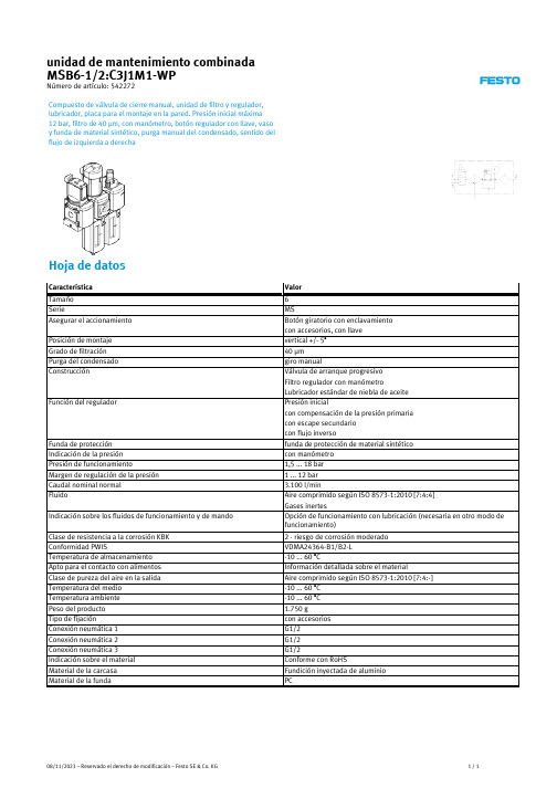
08/11/2023 – Reservado el derecho de modificación – Festo SE & Co. KG
1/1
Hoja de datos
Característica Tamaño Serie Asegurar el accionamiento
Posición de montaje Grado de filtración Purga del condensado Construcción
Función del regulador
Valor
6 MS Botón giratorio con enclavamiento con accesorios, con llave vertical +/- 5° 40 µm giro manual Válvula de arranque progresivo Filtro regulador con manómetro Lubricador estándar de niebla de aceite Presión inicial con compensación de la presión primaria con escape secundario con flujo inverso funda de protección de material sintético con manómetro 1,5 ... 18 bar 1 ... 12 bar 3.100 l/min Aire comprimido según ISO 8573-1:2010 [7:4:4] Gases inertes OpcБайду номын сангаасón de funcionamiento con lubricación (necesaria en otro modo de funcionamiento)
Eaton Moeller MSC-D DOL启动器商品说明书
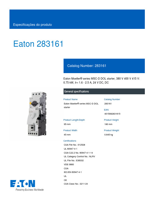
Eaton 283161Eaton Moeller® series MSC-D DOL starter, 380 V 400 V 415 V: 0.75 kW, Ir= 1.6 - 2.5 A, 24 V DC, DCGeneral specificationsEaton Moeller® series MSC-D DOL starter283161401508283161595 mm 180 mm 45 mm 0.645 kgCSA File No.: 012528 UL 60947-4-1CSA-C22.2 No. 60947-4-1-14 UL Category Control No.: NLRV UL File No.: E36332 VDE 0660 CSAIEC/EN 60947-4-1 UL CECSA Class No.: 3211-24Product NameCatalog Number EANProduct Length/Depth Product Height Product Width Product Weight CertificationsShort-circuit releaseTemperature compensated overload protection CLASS 10 AScrew terminalsNo2IP20NEMA OtherDirect starterDIN rail11.6 A2.5 AIII36000 V ACAlso motors with efficiency class IE3 Starter with Bi-Metal releaseDCFitted with: Functions ClassConnectionConnection to SmartWire-DTCoordination typeDegree of protectionModelMounting methodNumber of auxiliary contacts (normally closed contacts) Number of auxiliary contacts (normally open contacts) Overload release current setting - minOverload release current setting - maxOvervoltage categoryPollution degreeRated impulse withstand voltage (Uimp)Suitable forTypeVoltage typeMax. 2000 m -25 °C55 °C 1.9 A2.5 A0.37 kW0.75 kW230 - 415 V AC15 A, 600 V AC, (UL/CSA)1 A, 250 V DC, (UL/CSA)A600, AC operated (UL/CSA) P300, DC operated (UL/CSA)50000 A 38.8 A 2.6 W 0 V0 V0 V0 V 24 V 24 VAltitudeAmbient operating temperature - min Ambient operating temperature - max Rated operational current (Ie)Rated operational current (Ie) at AC-3, 380 V, 400 V, 415 V Rated operational power at AC-3, 220/230 V, 50 HzRated operational power at AC-3, 380/400 V, 50 HzRated operational voltageSwitching capacity (auxiliary contacts, general use) Switching capacity (auxiliary contacts, pilot duty)Rated conditional short-circuit current (Iq), type 2, 380 V, 400 V, 415 VShort-circuit release (Irm) - max Power consumption (sealing) at DCRated control supply voltage (Us) at AC, 50 Hz - min Rated control supply voltage (Us) at AC, 50 Hz - max Rated control supply voltage (Us) at AC, 60 Hz - min Rated control supply voltage (Us) at AC, 60 Hz - max Rated control supply voltage (Us) at DC - minRated control supply voltage (Us) at DC - max5.7 W0 W1.9 W2.5 A2.6 WMeets the product standard's requirements.Meets the product standard's requirements.Meets the product standard's requirements.Meets the product standard's requirements.Meets the product standard's requirements.Does not apply, since the entire switchgear needs to be evaluated.Does not apply, since the entire switchgear needs to be evaluated.Meets the product standard's requirements.Does not apply, since the entire switchgear needs to be evaluated.Meets the product standard's requirements.Does not apply, since the entire switchgear needs to be evaluated.DA-DC-00004910.pdfDA-DC-00004878.pdfeaton-manual-motor-starters-motorstarter-msc-d-dol-starter-dimensions.epseaton-manual-motor-starters-mounting-msc-d-dol-starter-3d-drawing.eps DA-CE-ETN.MSC-D-2,5-M7(24VDC)eaton-manual-motor-starters-device-msc-d-dol-starter-wiring-diagram.epsSimple, flexible and safe! Distribution system for motor-starter combinationsIL034014ZUIL034038ZUDA-CS-msc_d_bg1DA-CD-msc_d_bg1Equipment heat dissipation, current-dependent PvidHeat dissipation capacity PdissHeat dissipation per pole, current-dependent PvidRated operational current for specified heat dissipation (In) Static heat dissipation, non-current-dependent Pvs10.2.2 Corrosion resistance10.2.3.1 Verification of thermal stability of enclosures10.2.3.2 Verification of resistance of insulating materials to normal heat10.2.3.3 Resist. of insul. mat. to abnormal heat/fire by internal elect. effects10.2.4 Resistance to ultra-violet (UV) radiation10.2.5 Lifting10.2.6 Mechanical impact10.2.7 Inscriptions10.3 Degree of protection of assemblies10.4 Clearances and creepage distances10.5 Protection against electric shock10.6 Incorporation of switching devices and components Declarations of conformity DesenhoseCAD modelEsquemasFolhetosInstruções de instalação mCAD modelEaton Corporation plc Eaton House30 Pembroke Road Dublin 4, Ireland © 2023 Eaton. Todos os direitos reservados. Eaton is a registered trademark.All other trademarks areproperty of their respectiveowners./socialmediaDoes not apply, since the entire switchgear needs to be evaluated.Is the panel builder's responsibility.Is the panel builder's responsibility.Is the panel builder's responsibility.Is the panel builder's responsibility.Is the panel builder's responsibility.The panel builder is responsible for the temperature rise calculation. Eaton will provide heat dissipation data for the devices.Is the panel builder's responsibility. The specifications for the switchgear must be observed.Is the panel builder's responsibility. The specifications for the switchgear must be observed.The device meets the requirements, provided the information in the instruction leaflet (IL) is observed.10.7 Internal electrical circuits and connections 10.8 Connections for external conductors 10.9.2 Power-frequency electric strength 10.9.3 Impulse withstand voltage 10.9.4 Testing of enclosures made of insulating material 10.10 Temperature rise10.11 Short-circuit rating10.12 Electromagnetic compatibility10.13 Mechanical function。
IMI Cornelius JT-30 冷饮饮料机用户手册说明书
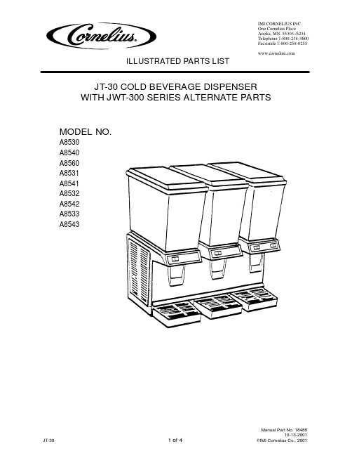
ILLUSTRATED PARTS LISTJT-30COLD BEVERAGE DISPENSER WITH JWT-300SERIES ALTERNATE PARTSMODEL NO.A8530A8540A8560A8531A8541A8532A8542A8533A8543 ILLUSTRATED PARTS LISTJT-30COLD BEVERAGE DISPENSERWITH JWT-300SERIES ALTERNATE PARTSFIGURE1.GENERAL ASSEMBLYILLUSTRATED PARTSLISTJT-30COLD BEVERAGE DISPENSER WITH JWT-300SERIES ALTERNATE PARTSItem No.Part No.Name1S6670Tube Spray2S6677Housing Pump Asy120V 60HZ S7046Pump Asy 220/240V 50HZ 3A3058Impeller and Support Pin 120V 60HZA3192Impeller and Support Pin 220/240V 50HZ 4A2549Pin Support Impeller 5S6676Cover Bowl 5Gallon A2162Cover Bowl 3Gallon 6S6562Bowl 5Gallon A0791Bowl 3Gallon7S6737Impeller Circ Asy (Replace of Pump Housing Ass’y No.S6677for Certain Drinks)8A1620Impeller Circ Asy A3036Lock DeviseA3791Kit Extension Leg 9S4206Tube Pinch10S6901Gasket Bowl Spout 11S6600Gasket Bowl12S4381Handle Push Asy137********Label Oper Push Handle 14S4363Tube Pinch Spring15S4576Rivet Spr Ret (Pack of 6)16Item Not used 17Item Not used1818546Capac 208/230V 60HZ 19S6657Thermostat 120V 60HZ A2739Thrmst Asy 220/240V 50HZ 2018334Switch On-Off21A1753Motor Asy Spray Drive 120V 60HZA2072Spray Drive Asy 220/240V 50HZ 2218874Magnet Asy23A8364Kit Comp 1/3HP 120V 60HZ A8365Kit Comp 1/3HP 230V 50HZ A8366Kit Comp 1/3HP 230V 50/60HZ 24A1839Motor Asy Fan 8”Dia Fan Blade 120V 60HZA4493Motor Asy Fan 83/4”Dia Fan Blade 120V 60HZA2148Motor Asy Fan 8”Dia Fan Blade 220/240V 50HZ (No Longer Available)A4446Motor Fan 9W 120V 60HZ A4451Blade Fan 17898Cond 18449DryerItem No.Part No.Name14512Fan Ass’y,83/4”Dia Fan Blade,220/240V 50HZ (No Longer Available)A4448Motor Fan 9W 230V 50HZ 3714Brkt Fan25S3194Motor Fan 5W 120V 60HZ A4446Motor Fan 9W 120V 60HZ S3195Motor Fan 6W 230V 50HZ A4448Motor Fan 9W 230V 50HZ 26S1249Cord Serv 120V 60HZ 7215130Cord,Asy 230V 50HZ 2712086Relay Start 120V 60HZ 12576Relay Start 230V 50HZ 18545Relay 208/230V 60HZ 2818369Overld,120V 60HZ 350106Overld 230V 50HZ 18547Overld 208/230V 60HZ 2918334Switch On-Off 30Item Not used31A7319Panel Back Asy Vnt Cvr 32A7316Panel Back Asy Wht 33S3159Leg Set Replacement 34Item Not used35S7683Switch and Cover PlateS9281Plate Switch Cover (No Longer Available)36S9267Panel Fnt(Serial No.below 315270)18720Panel Fnt(Serial No.315270and above)37S9266Panel Side Asy A2011Filter Side Panel 38A7310Drip Tray Asy(Serial No.below 315270)18747Drip Tray Asy(Serial No.315270and above)39A7296Drip Tray Asy(Serial No.below 315270)18747001Drip Tray(Serial No.315270and above)4018747002Cup Rest41S4554Screw Panel (Pack of 12)42A3060Screw Side Clip (Pack of 4)43S7289Drain Asy Condensate 44A2081Spacer Cover Mntg Hdwr 45A7317Panel Back with Filter A2013Filter46A7305Frame SideILLUSTRATED PARTSLISTJT-30COLD BEVERAGE DISPENSER WITH JWT-300SERIES ALTERNATEPARTSFIGURE 2.JWT ALTERNATE PARTSItem No.Part No.Name1A2746Housing Whipper2A2566Magnet Whipper Impeller 3A0116Pin Whipper Impeller 4A0938Union Whipper Outlet 5S7395Outlet Tube6A2569Chamber Whipper 7A0423Clip Impeller Support 8S7394Tube Vent Asy 5-Gallon A2791Tube Vent Asy 3-Gallon 9A2256Motor Whipper 120V 60HZ S7512Motor Whipper 230V 50HZ 10A2567Motor Asy Whipper 120V 60HZ A2645Motor Whp Asy 230V 50HZ (No Longer Available)11A2410Magnet Asy DoubleItem No.Part No.Name12S8465Switch Motor White A2754Switch Motor Black13S8469Kit Screen and Washr (Pack of 4)8468Washer Star No.108469Screw No.10-32x 1/41413927Plate Cover SwitchS9412Plate Cover Switch (No Longer Available)15A2269Cover Switch Asy White (No Longer Available)A4509Cover Switch Asy Black (No Longer Available)16S8467Switch Support Asy White (No Longer Available)A4434Switch Support Plate Black (No Longer Available)17S9570Cover Plate Switch Non Whipper (No Longer Available)。
Olympia Vulcanika Series产品说明书

Series PORCELAINGLAZED PORCELAINAll items shown in this document are part of Olympia’s stocking program. For special orders, please contact yourOlympia Tile Sales Representative.30 x 60 cm (12” x 24”)Matte RZ.VK.WHT.1224.MT 30 x 60 cm (12” x 24”)Matte RZ.VK.GRY.1224.MTWHITE LAVIKAGREY LAVIKAAll items shown in this document are part of Olympia’s stocking program. For special orders, please contact your Olympia Tile Sales Representative.30 x 60 cm (12” x 24”)Matte RZ.VK.BLK.1224.MTBLACK LAVIKAAll items shown in this document are part of Olympia’s stocking program. For special orders, please contact yourOlympia Tile Sales Representative.30 x 60 cm (12” x 24”)Semi- Polished RZ.VK.BIA.1224.SP 30 x 60 cm (12” x 24”)Semi- Polished RZ.VK.VRD.1224.SPBIANCO (White) RAKUVERDE (Green) RAKUAll items shown in this document are part of Olympia’s stocking program. For special orders, please contact yourOlympia Tile Sales Representative.30 x 60 cm (12” x 24”)Semi- Polished RZ.VK.BLU.1224.SPBLU RAKU30 x 60 cm (12” x 24”)Semi- Polished RZ.VK.NRO.1224.SPNERO (Black) RAKUVulcanika Series - Glazed Porcelain(Rectified)30 x 30 cm (12” x 12”)Semi- Polished RZ.VK.BIA.1212.DC30 x 30 cm (12” x 12”)Semi- Polished RZ.VK.BLU.1212.DC30 x 30 cm (12” x 12”)Semi- Polished RZ.VK.VRD.1212.DC BIANCO (White) RAKUKarato DecorBLU RAKUKarato DecorVERDE (Green) RAKUKarato Decor30 x 30 cm (12” x 12”)Semi- Polished RZ.VK.NRO.1212.DCNERO (Black) RAKUKarato DecorAll items shown in this document are part of Olympia’s stocking program. For special orders, please contact your Olympia Tile Sales Representative.Water AbsorptionASTM C373< 0.5%ConformsColour VariationMemberMember of Canada Green BuildingCouncilMember of U.S. Green BuildingCouncilFor information concerning LEED, please contact our Sales Representative12” x 24” Lavika Matte 611.6253.824012” x 24” Raku Semi-Polished 611.6252.884012” x 12” Raku Karato Decor SP1211.6252.3240Packing DetailsExamples of Recommended ApplicationsResidentialCommercialIndoorOutdoorWallFloorTechnical data is supplied by the manufacturer and is subject to change at any time. Olympia does not provide warranties as to the specifications of any product.Distributors of America (CTDA)The Terrazzo, Tile, and Marble Association ofCanadaMarble Institute of AmericaTaskGrout Sealing MORE™ Grout, Ceramic &Porcelain Sealer Ready to use Commercial: 1-3 Years Residential: 5-8 YearsDaily Maintenance MORE™ Stone and TileCleaner 1 : 128 Ratio Daily Deep Cleaning MORE™ Alkaline Cleaner 1 : 4 Ratio As Needed Grout Haze- CementitiousMORE™ Acidic Cleaner 1 : 4 Ratio As Needed Grout Haze - Epoxy / UrethaneMORE™ Coating Stripper*Ready to useAs Needed* Always test in an inconspicuous area to make sure the product is achieving the desired results and is not damaging the finish of the surface.SURFACE PREPARATION (If Required)• Floor levelling: 59 Flex Flo / 5900 Flex Flo Plus Self Levelling Underlayment • Waterproofing: WP900 Waterproof Membrane• Crack Isolation/Uncoupling: Flexilastic 1000 Crack Isolation Membrane / FlexMat Uncoupling Membrane* For a complete listing of FLEXTILE products and accessories including Sound Control, In‐Floor Heating, and further setting options, please visit BLU RAKU KARATO DECOR (Semi-Polished)It is Olympia Tile’s policy to stock all items for sale. Should you require additional sizes, finishes or colours, Olympia has a Special Order Department to help find exactly what you are looking for. Please contact your Olympia Tile Sales Representative for more details. Note that minimum order quantities and longer lead times apply to all special order items.Colour may vary slightly from images shown. It is highly recommended to view physical samples of tile prior to purchase. Note that shade variations between tiles is characteristic and adds to the inherent beauty of the product. Please visit a showroom near you or request a sample from your Olympia Tile Sales Representative.Vulcanika Series: Board MEF-116 / Folder FL-715CORPORATE OFFICE 701 Berkshire Lane North Minneapolis (Plymouth) Minnesota 55441 T: 763 545 5455 F: 763 542 9830 FLORIDAALPHA TILE & STONE 2443 East Meadow Blvd.Tampa , Florida 33619T: 813 620 9000TollFree:180****9000F: 813 621 0606 10898-A Metro Parkway Fort Myers , Florida 33966T: 239 275 8288TollFree:180****8288F: 239 275 01162603 Ace RoadOrlando , Florida 32804T: 407 293 3993TollFree:180****3993F: 407 293 17791808 Whitfield Ave.Sarasota , Florida 34243T: 941 727 7433TollFree:180****3484F: 941 727 7381IOWAKATE-LO TILE & STONE 4251 N.W. Urbandale Dr. Des Moines (Urbandale)Iowa 50322T: 515 270 4920TollFree:180****1387F: 515 270 7035NORTH DAKOTAKATE-LO TILE & STONE Resource Centre300 Northern Pacific Ave.Suite 106Fargo , North Dakota 58102T: 701 478 8087F: 701 478 8084MICHIGANBEAVER TILE & STONE 24700 Drake Rd.Detroit West(Farmington Hills)Michigan 48335T: 248 476 2333TollFree:180****0551F: 248 476 46361700 Stutz Dr., Suite 101Detroit North (Troy)Michigan 48084T: 248 649 5552F: 248 649 07412780 Enterprise Ct.Saginaw , Michigan 48603T: 989 790 5851TollFree:180****0897F: 989 790 031113085 23 Mile Rd.Detroit East(Shelby Township)Michigan 48315T: 586 991 0780TollFree:180****5395F: 586 991 07841694 Gezon ParkwayGrand Rapids, (Wyoming)Michigan 49509T: 616 534 2883TollFree:180****0727F: 616 534 4784MINNESOTAKATE-LO TILE & STONE 701 Berkshire Lane North Minneapolis (Plymouth)Minnesota 55441T: 763 545 5455TollFree:180****3026F: 763 542 9830NEBRASKAKATE-LO TILE & STONE 13211 Chandler Road Suite 400Omaha (La Vista)Nebraska 68138-3703T: 402 614 9010TollFree:187****6636F: 402 614 0989NEW JERSEYNEW JERSEY TILE & STONE70 Newfield Avenue Raritan Center, EdisonNew Jersey 08837T: 732 512 1818TollFree:180****8453F: 732 512 1881NEW YORKDOBKIN TILE & STONE 51 Benbro DriveBuffalo (Cheektowaga)New York 14225T: 716 684 1200TollFree:180****1414F: 716 684 129448 Railroad Avenue Albany (Colonie)New York 12205T: 518 489 6803TollFree:180****5769F: 518 489 6806OREGONTHOMPSON TILE & STONE 4472 NW Yeon Avenue PortlandOregon 97210T: 503 225 1273TollFree:180****4092F: 503 222 0731WISCONSINLEXCO TILE & STONE 1616 S. 108th Street MilwaukeeWisconsin 53214T: 414 771 2900Toll Free: 1 800-242-2249F: 414 771 9153WASHINGTONTHOMPSON TILE & STONE 3900 East Alki SpokaneWashington 99208T: 509 535 2925TollFree:180****2555F: 509 534 5218711 S. Fidalgo Street SeattleWashington 98108T: 206 900 7331TollFree:180****4093F: 206 294 5933575 Strander Blvd.TukwilaWashington 98188T: 206 575 7976F: 206 575 7484OL YMPIA TILE + STONE INTERNATIONAL INC.OL YMPIA TILE (USA), INC.TORONTO121 30th Street l Toronto l Ontario l M8W 3C1T: 416 255-1111 l Toll Free: 1 800 699 3623 l F: 416 255-1729VANCOUVER2969 Lake City Way l Burnaby l British Columbia l V5A 2Z6 T: 604 420-4914 l Toll Free: 1 888 236 4486 l F: 604 420-0936FLEXTILE LTD.MANUFACTURING PLANTS CORPORATE OFFICE AND SHOWROOM TORONTO1000 Lawrence Ave. West Ontario M6A 1C6T: 416 785 6666TollFree:180****1613F: 416 785 9682VAUGHAN100A Royal Group CrescentOntario L4H 1X9T: 905 266 0420F: 905 266 0423VANCOUVER2350 Willingdon Ave.BurnabyBritish Columbia V5C 5J6T: 604 294 2244TollFree:180****9441F: 604 294 0528CALGARY3308 - 11th Street S.E.Alberta T2G 3G8T: 403 287 1070TollFree:180****8182F: 403 243 1888EDMONTON11540 - 163rd Street Alberta T5M 3T3T: 780 452 5050TollFree:180****4438F: 780 451 4391WINNIPEG560 Sheppard Street Manitoba R2X 2P8T: 204 633 5736TollFree:180****8017F: 204 632 4644WINDSOR4145 7th Concession Rd Ontario N9A 6J3T: 519 966 2500TollFree:187****5953F: 519 969 2407LONDON234 Exeter Road Ontario N6L 1A3T: 519 652 5011TollFree:180****4690F: 519 652 5021HAMILTON 75 Milburn Road Ontario L8E 3A3T: 905 560 5520TollFree:180****1370F: 905 578 3593OTTAWA2480 Don Reid Drive Ontario K1H 1E1T: 613 736 9570TollFree:180****1864F: 613 736 9563MONTREAL 555 rue Locke Ville St-Laurent, Quebec H4T 1X7T: 514 345 8666TollFree:180****1954F: 514 345 8825QUEBEC2405 rue Watt Quebec G1P 3X2T: 418 657 5557TollFree:180****5516F: 418 657 6708HALIFAX55 Akerley Boulevard Dartmouth, Nova Scotia B3B 1M3T: 902 468 9260TollFree:180****7790F: 902 468 0011TORONTO 22 Dufflaw RoadToronto, Ontario M6A 2W1 T: 416 785 9555 ext 320F: 416 781 4521VAUGHAN100A Royal Group Crescent Vaughan, Ontario L4H 1X9 T: 905 266 0420F: 905 266 0423SLAB DIVISION。
手套箱Mikrouna使用说明书
目录一、常用操作 (2)1、开机 (2)2、关机 (2)3、物品放入手套箱 (2)4、物品拿出手套箱 (3)5、清洗 (3)6、再生 (3)7、水探头清洗(仅限于可清洗的探头) (4)二、日常维护 (4)三、常见故障及解决办法 (5)一、常用操作1、开机1)打开主电源开关(红色)2)打开工作气减压阀(主阀门开到最大、副阀门开到0.4~0.6Mpa)3)启动循环(循环为24小时开启)。
4)启动分析仪(氧指标在水指标降到200ppm以下时开始显示)5)启动冷却水循环机(如果有的话)6)将箱体压力设置为:+1~+6mbar2、关机1)关闭水氧分析仪2)关闭循环3)关闭真空泵4)关闭冷却水循环机5)关闭工作气减压阀主阀6)关闭主电源开关3、物品放入手套箱1)给过渡舱补气、补气结束后关闭2)打开外舱门3)把物品放入舱内4)关闭外舱门5)抽气、补气各三次(液晶屏、密闭瓶子等不能抽太大负压的,可酌情减少抽气时间,增加抽气次数)6)打开内舱门7)取出物品8)关闭内舱门并随手抽一点负压PS:禁止将吸水性的物品如抹布、纸巾等直接放入,放入前先烘干!禁止在负压下试图打开内外舱门!禁止操作手套时手上带有戒指、手表等可破坏手套的物件。
(最好手套内外再各加一副手套,总三副手套)!4、物品拿出手套箱1)给过渡舱补气、补气结束后关闭2)打开内舱门(注意:打开前先确保舱内气氛为纯净,无法确定,需先抽气、补齐三次,使其纯净)3)把物品放入舱内4)关闭内舱门5)打开外舱门6)取出物品7)关闭外舱门并随手抽一点负压5、清洗1)定义:用工作气体置换箱内的气体,箱内气体从手套箱顶上的清洗阀排出2)步骤:①确保工作气充足;②关闭循环;③开启真空泵④开启清洗3)使用:①首次调试;②长时间未启用;③误操作,使得空气进入④清除箱内有机溶剂、酸碱溶剂等对手套箱有害的物质(有机溶剂等含量过高会影响氧探头和循环系统正常工作)6、再生1)再生气:氢气和惰性气体的混合气(氢气占5%-10%)2)再生气压力:0.06Mpa~0.08Mpa,小于0.1Mpa3)数量:40L的气瓶不小于10Mpa4)过程:3小时加热+3小时通气+18小时冷却及抽真空5)步骤:①连接再生气(连接后检查管路是否漏气:连接好后把减压阀主阀开到最大,把副表开到0.1Mpa,关掉主阀,等待15分钟,如果副表压力保持0.1Mpa不变,说明没有漏气)②将减压阀副表压力设置为0.1Mpa(通气时压力约为0.06-0.08MPa)③关闭循环和分析仪④打开真空泵⑤启动再生⑥24小时后再生自动结束6)注意:再生过程(尤其前6个小时)切勿断电断气!有些减压阀不准,需适当调节压力以保证3小时持续通气!7、水探头清洗(仅限于可清洗的探头)1)若水探头长时间不清洗,表面会附着一些脏东西,影响探测2)步骤:①关闭循环和分析仪②将工作压力设置为+5至+8mbar③拆下水探头,迅速用盲板盲住出气口④拧下探头前端的金属保护罩,用去离子水清洗,再用无尘纸擦干,再滴3~5滴清洗液清洗,再用无尘纸擦干⑤装回原处,打开循环,3分钟后打开分析仪,待半小时后可恢复正常水平二、日常维护1)操作手套箱后及时填写使用记录,包括“使用人、水氧值、做何操作”。
罗红霉素胶囊说明介绍模板之欧阳计创编
罗红霉素胶囊说明书【药品名称】通用名:罗红霉素胶囊英文名:Roxithromycin Dispersible Capsules汉语拼音:Luohongmeisu Jiaonang本品主要成分为罗红霉素,化学名为9—[O—[(2-甲氧基乙氧基)-甲基]肟]红霉素。
分子式:C41H76N2O15分子量:837.03【性状】本品为胶囊剂。
【药理毒理】本品为半合成的14元环大环内酯类抗生素。
抗菌谱与抗菌作用基本上与红霉素相仿,对革兰阳性菌的作用较红霉素略差,对嗜肺军团菌的作用较红霉素强。
对肺炎衣原体、肺炎支原体、溶脲脲原体的抗微生物作用与红霉素相仿或略强。
本品可透过细菌细胞膜,在接近供体(“P”位)与细菌核糖体的50S亚基成可逆性结合,阻断了转移核糖核酸(t-RNA)结合至“P”位上,同时也阻断了多肽链自受位(“A”位)至“P”位的转移,因而细菌蛋白质合成受到抑制。
【药代动力学】口服吸收好,血药峰浓度(Cmax)高,单剂量口服罗红霉素150 mg后约2小时达血药峰浓度(Cmax)6.6~7.9 mg/L,进食可使生物利用度下降约一半。
分布广,扁桃体、鼻窦、中耳、肺、痰、前列腺及其他泌尿生殖道组织中的药物浓度均可达有效治疗水平。
其蛋白结合率在血浓度2.5 mg/L时为96%。
以原形及5个代谢物从体内排出,7.4%自尿液排出。
血消除半衰期(t1/2?)为8.4~15.5小时。
【适应症】本品适用于化脓性链球菌引起的咽炎及扁桃体炎,敏感菌所致的鼻窦炎、中耳炎、急性支气管炎、慢性支气管炎急性发作,肺炎支原体或肺炎衣原体所致的肺炎;沙眼衣原体引起的尿道炎和宫颈炎;敏感细菌引起的皮肤软组织感染。
【用法用量】空腹口服,一般疗程为5~12日。
成人一次150mg,一日2次;也可一次300mg,一日1次。
儿童一次按体重2.5~5mg/kg,一日2次。
【不良反应】主要不良反应为腹痛、腹泻、恶心、呕吐等胃肠道反应,但发生率明显低于红霉素。
Merrithew Corporation 药球杠架说明书
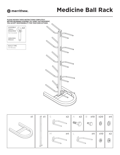
Medicine Ball RackPLEASE REVIEW THESE INSTRUCTIONS COMPLETEL YBEFORE BEGINNING ASSEMBL Y. BY USING THIS EQUIPMENT,BUILD TIME30 MinutesSTEP 1STEP 2IMPORTANTThis manual contains important assembly, safety and warranty information. Read the manual carefully before using your new Medicine Ball Rack and keep the manual on hand for future reference.UNSAFE OR IMPROPER USE OF THIS MEDICINE BALL RACK BY FAILING TO READ AND COMPL Y WITH ALL REQUIREMENTS AND WARNINGS COULD RESULT IN SERIOUS INJURY.It is impossible to predict every situation and condition that can occur while using this Medicine Ball Rack. Merrithew™ makes no representation about the safe use of any Medicine Ball Rack that cannot be predictedor avoided.PLEASE READ THESE INSTRUCTIONS COMPLETEL Y BEFORE BEGINNING ASSEMBL Y. BY USING THIS EQUIPMENT, YOU ACCEPT RESPONSIBILITY FOR YOUR OWN ACTIONS.SAFETY AND USAGE• Use only for intended purposes• Intended for Medicine Balls, maximum of 10 per rack• T o prevent tipping, fill rack from bottom up• Can safely hold Medicine Balls that are up to 22 lbs/10 kg• Maximum total weight capacity 220 lbs/100 kg• Do not hang from the rack or allow children to hang from the rack• Select a level area of the room to keep the Medicine Ball Rack andtake caution when storing in high-tra c areasCARE AND CLEANINGWipe surfaces using warm water with mild soap and clear water rinsesfor day-to-day cleaning. Ensure soap does not leave an oily residue or make surfaces slippery. CAUTION: We do not recommend usingchemical-based products. The warranty does not cover this damage.ASSEMBLY TOOLS REQUIREDAdjustable wrench (x2) needed for assembly.WARRANTYMerrithew warrants that all new equipment is free of manufacturing defects in workmanship and materials, subject to the terms below. This warranty becomes e ective at the invoice date of the original purchase. Parts repaired or replaced under the terms of this warranty will be warranted for the remainder of the original warranty period.It is the purchaser’s responsibility to notify the Company of any changeof contact information. This ensures, that in the unlikely event of a replacement or safety notice, we are able to contact you immediately. This warranty applies to equipment only:• While it remains in the possession of the original purchaser andproof of purchase is demonstrated• If claims are made within the part-specific warranty period• If upgrades are made as required by MerrithewThis warranty shall be null and void if:• Equipment failure is a result of improper assembly, installation or maintenance• The equipment is used for any other purpose other than as intended, or is stored or used outdoors, or in environments without adequate climate/humidity controls• Equipment has been subjected to accident, misuse, abuse, improper service, or any modification not authorized by MerrithewThis warranty does not cover damage to the finish of any equipment nor shipping charges, customs clearance fees (if applicable), or any costs incurred in installing repaired or replacement parts shipped under the provisions of this warranty.Thirty (30) Day Limited WarrantyThirty (30) Day Limited Warranty Merrithew will, at its option, repair, replace or credit the Medicine Ball Rack if it fails for any reason, provided such failure is reported to Merrithew within a period of thirty (30) days from the-invoice date of the original-purchase.Disclaimer of Implied Warranties and Limitation of RemediesRepair or replacement of defective parts is your exclusive remedy under the terms of this limited warranty. In the event of parts availability issues, Merrithew will not be responsible for any consequential or incidental damages arising from the breach of either this limited warranty or any applicable implied warranty, or for failure or damage resulting from acts of nature, improper care and maintenance, accident, alteration, replacement of parts by anyone other than Merrithew, misuse, transportation, abuse, hostile environments (inclement weather, acts of nature), improper installation or installation not in accordance with local codes or printed instructions.This limited warranty is the sole express warranty given by Merrithew. No product performance, specification or description wherever appearing is warranted by Merrithew except to the extent set forth in this limited warranty. Any implied warranty protection arising under the laws of any state, province or territory including implied warranty of merchantability or fitness for a particular purpose, or use, is hereby limited in duration to the duration of this limited warranty.Neither distributors, dealers, web resellers, nor the retailers selling this product have any authority to make any additional warranties or to promise remedies in addition to, or inconsistent with those stated above. Merrithew’s maximum liability, in any event, shall not exceed the purchase price of the product paid by the original purchaser.2200 Yonge Street, Suite 500, T oronto, Ontario, Canada M4S 2C6 416.482.4050 | 1.800.910.0001 | 0800.328.5676 UK | ext. 0907**************************|**************************PM-0006A-1 NOV18 ™/® Trademark or registered trademark of Merrithew Corporation, used under license. All rights reserved.。
Atlas Copco LMS 影响螺纹扳手系列产品说明书

IMPACT WRENCHESIntroduction – Impact WrenchesPower you can depend onAtlas Copco´s powerful, high-speed im-pact wrenches are designed to cut pro-duction times by providing rapid run-down and fast tightening. Impact wrenches build up torque in joints through a series of rotary impacts, where air pressure and tightening time affect the torque obtained. As a general rule, if a wrench impacts longer than 5 seconds on a fastener, a larger wrench should be used in order to achieve better durability.The LMS models are non shut-off, which means they will shut off once the operator releases the trigger.LMSThe LMS is a non shut-off impact wrench with extraordinary power to weight quali-ties and virtually no reaction force during tightening. The torque is applied to the joint, not to your wrist.These tools are typically used where fast tightening or disassembly is needed and the range covers recommended torque levels between 7-5500 Nm.LMS 8-SERIESThe new LMS 8-series impact wrenches delivers true raw power and enables ex-tremely fast tightening and loosening.The innovative and unique Grease Re-taining System ensures maximum tool performance with long service intervals.MINIMUM WEAR AND LOW VIBRATIONSEach part of the durable LMS8-Series im-pact mechanism is produ c ed with a very precise accuracy. This allows the maxi-mum amount of energy to be generated in each impact. It also minimizes wear, vibration and strain on the operator.Atlas Copco impact wrenches are designed to provide dependability and a long, trouble-free service life in the toughest conditions. Few other tools can match the Atlas Copco impact wrench when it comes to flexibility, capacity-to-weight ratio and simplicity in use and maintenance.= =Selection GuideHEAVY DUTYEXTRA HEAVY DUTYThe torque figures are normal tightening torque for untreated oil-smeared and rust-protected bolts and nutsin the most common strength grades. The torque figures correspond to approximately 63% of tensile stress.LMS58 HR25LMS18 HR13LMS68 HR S522-30 1 5/8 600-1800 442-1400 4450 3282 780 5000 9.8 21.5 252 55 28 58.9 16 1/2 8434 1680 03Non Shut-offPistol Grip Modelsa Female hex. quick change chuck.bSpline drive No. 5.cPin retainer dThrough hole eFriction ringLMS MODELSlRecommended operating range 7-1800 Nm.l Fast tightening and disassembly.l Negligible reaction force.l Low weight.lHigh power-to-weight ratio.l Tightening time should not exceed 5 seconds, to avoid excess wear on the tool.l Soft-start throttle.l Long service intervals.l Durable high performance with Grease Retaining System.LMS08 SR10LMS88 GIR38LMS68 GIR25d b d b a Female hex. quick change chuck. bSpline drive No. 5.cPin retainer dThrough holeGOR = Outside trigger.GIR = Inside trigger.LMS MODELSlRecommended operating range 7-5500 Nm.l Fast tightening and disassembly.l Negligible reaction force.l Low weight.lHigh power-to-weight ratio.l Soft-start throttle.l Tightening time should not exceed 5 seconds, to avoid excess wear on the tool.l Long service intervals.l Durable high performance with grease retaining system.Non Shut-offStraight ModelsOptional AccessoriesAccessoriesWhip hoseMULTIFLEX SWIVELWHIP HOSEProductivity KitsThe spare parts included in the servicekits cover a normal overhaul of your tool.Always have them available for a fastand economical repair.Main parts included:l Gaskets l O-ringsl Circlips l Pins etc.Service KitsMultiFlex SwivelSuspension yoke included LMS08-58。
- 1、下载文档前请自行甄别文档内容的完整性,平台不提供额外的编辑、内容补充、找答案等附加服务。
- 2、"仅部分预览"的文档,不可在线预览部分如存在完整性等问题,可反馈申请退款(可完整预览的文档不适用该条件!)。
- 3、如文档侵犯您的权益,请联系客服反馈,我们会尽快为您处理(人工客服工作时间:9:00-18:30)。
【药品名称】
通用名称:骨化三醇胶丸
商品名称:骨化三醇胶丸(海卡洛)
拼音全码:GuHuaSanChunJiaoWan(HaiKaLuo)
【主要成份】本产品主要成分是骨化三醇。
【性状】本品为胶丸,内含黄色或淡黄色油状液体。
【适应症/功能主治】1.绝经后骨质疏松;2.慢性肾功能低下;3.术后甲状腺功能低下;4.特发性甲状旁腺功能低下;5.假性甲状腺功能低下;6.维生素D依赖性佝偻病;7.低血磷性维生素D抵抗型佝偻病等。
【规格型号】0.25μg*10s
【用法用量】应根据每个病人血钙水平小心制定本品的每日最佳剂量。
开始以本品治疗时,应尽可能使用最小剂量,并且不能在没有监测血钙水平的情况下增加用量。
【不良反应】由于骨化三醇能产生维生素D的作用,所以可能发生的不良反应与维生素D过量相似。
如高血钙综合症或钙中毒(取决于高钙的严重程度及持续时间)。
偶见的急性症状包括食欲减退、头痛、呕吐和便秘。
慢性症状包括营养不良、感觉障碍,拌有口渴的发热、尿多、脱水、情感谈漠,发育停止及泌尿道感染。
长达15年临床使用本品治疗所有适应症。
结果显示不良反应发生率很低,包括高钙血症在内的发生率为0.111%或更低。
并发高钙和高磷血症的病人(浓度大于6mg/100mmol/l)可能发生软组织钙化,这些表现可通过放射学检查而观察到。
肾功能正常的病人,慢性高钙血症也许与血肌酐增高有关。
由于骨化三醇的生物半衰期较短,其药代动力学研究表明,停药或减量数天后升高的血钙即回复正常范围,这一过程要比维生素D3快许多。
对敏感体质的病人可能会发生过敏反应。
【禁忌】本品禁用有维生素D中毒迹象的病人。
【注意事项】
1.高血钙同本品的治疗密切相关。
对尿毒症骨营养不良病人的研究表明,高达40%使用骨化三醇治疗的病人中发现高血症。
饮食改变(例如:增加奶制品的摄入)以至钙摄入量迅速增加或不加控制的服用钙制剂均可导致高血钙。
应告知病人及其家属,必须严格遵守处方饮食,并教会他们如何识别高钙血症的症状。
一旦血钙浓度比正常值(9~11mg/100ml,或2250~2750ugmol/l)高出1ml/100ml,或血肌酐升高到大于120umol/ml,应立即停止服用本品直至血钙正常。
(祥见“用法用量”)肾功能正常的患者,慢性高血钙可能与血酐增加有关。
卧床病人,如术后卧床病人发生高钙血机会更大些。
2.骨化三醇能增加血无机磷水平,这时低磷血症的病人是有益的,但对肾功能衰竭的病人来说则要小心不正常的钙沉淀所造成的危险,在这种情况下,要通过口服适量的磷结合剂或减少磷质摄入量将血磷保持在正常水平(2~5mg/100ml或0.65~1.62mmol/l)。
患维生素D抵抗性佝偻病人(家族性低磷血症),以本品治疗时应继续口服磷制剂。
但必须考虑本品可能促进肠道对磷的吸收,这种作用可能使磷的摄入需要
量减少。
因此需要定期进行稳定期,每周至少测定血钙两次。
(详见“用法用量”)
3.由于骨化三醇是现有的最有效的维生素D代谢产物,故不需要其他维生素D制剂与其合用,从而避免高维生素D血症。
如果病人由服用维生素D3改服用骨化三醇时,则可能需要数月时间使血中维生素D3恢复至基础水平。
(详见“用法用量”)
4.肾功能正常的患者服用本品时必须避免脱水,故应保持适当的水摄入量。
5.对驾驶车辆和操作机器的影响。
基于所报道的不良反应的药效学特性,推测本品对驾驶车辆及操作机器是安全的或者说影响很小。
【儿童用药】尚不明确。
【老年患者用药】尚不明确。
【孕妇及哺乳期妇女用药】尚不明确。
【药物相互作用】勿与含镁的抗酸剂合用。
【药物过量】尚不明确。
【药理毒理】本药是一种人工制造的钙化三醇,制成无菌等渗澄清之水溶液用于静脉注射,除活性成分外,本药还含有聚氧乙烯山梨醇脂肪酸脂20.4 mg ;氯化钠1.5 mg ;抗坏血酸钠10 mg ;无水磷酸二氢钠7.6 mg ;一水磷酸一氢钠1.8 mg ;依地酸二钠加至1.1 mg,酸碱度接近pH 7.2 (6.5-8.0),钙化三醇是一种无色结晶的化合物,自然存在于人体之内,它溶于有机溶剂,但不太溶于水,其化学名为9,10开环胆固醇--5,7,10⒆-三烯-1-α-3-β25三酮,常用名为1-α-25-二羟胆钙化醇或1-α-25-二羟维生素D3,钙化三醇是维生素D3(胆钙化醇)衍生的具有药理活性的物质,维生素D由自然或内生供给,人类主要依靠紫外光照射,皮肤把7-脱氢胆固醇转化为维生素D3,维生素D3在其靶组织进行完全作用之前,必须在肝脏和肾脏发生代谢作用,首次转化需要存在于肝脏的维生素D325羟化酶催化,生成25-羟-D3,下一羟化作用在肾组织的线粒体中进行,通过肾的25羟维生素D31-α-羟化酶的激活,反应生成1,25-二羟D3,这是维生素D3的有效作用形式,钙化三醇的作用部位是小肠,骨,肾和甲状旁腺,可刺激小肠转运钙的作用,促进小肠吸收钙,并能与甲状旁腺激素协同促进对钙的回吸收,不增加肾小管重吸收钙,钙化三醇还可直接抑制甲状旁腺激素的合成和分泌,尿毒症病人会发生抗维生素D,这是因为肾衰竭时,无法把钙化三醇的前体转化为活性化合物钙化三醇。
【药代动力学】尚不明确。
【贮藏】遮光密闭,置阴凉处。
【包装】0.25ug*10粒/盒。
【有效期】36 月
【批准文号】HC20100032
【生产企业】CHIN TENG PHARMACEUTICAL INDUSTRIAL CO., LTD。
