HF2100-1C09DXXX中文资料
FSFR2100XS;FSFR2100XSL;中文规格书,Datasheet资料

FSFR-XS Series — Fairchild Power Switch (FPS ™) for Half-Bridge Resonant ConverterFeatures Variable Frequency Control with 50% Duty Cycle for Half-Bridge Resonant Converter TopologyHigh Efficiency through Zero Voltage Switching (ZVS) Internal UniFET™ with Fast-Recovery Body Diode Fixed Dead Time (350ns) Optimized for MOSFETs Up to 300kHz Operating FrequencyAuto-Restart Operation for All Protections with External LV CCProtection Functions: Over-Voltage Protection (OVP), Over-Current Protection (OCP), Abnormal Over-Current Protection (AOCP), Internal Thermal Shutdown (TSD)Applications PDP and LCD TVsDesktop PCs and Servers AdaptersTelecom Power SuppliesDescriptionThe FSFR-XS series includes highly integrated power switches designed for high-efficiency half-bridge resonant converters. Offering everything necessary to build a reliable and robust resonant converter, the FSFR-XS series simplifies designs while improving productivity and performance. The FSFR-XS series combines power MOSFETs with fast-recovery type body diodes, a high-side gate-drive circuit, an accurate current controlled oscillator, frequency limit circuit, soft-start, and built-in protection functions. The high-side gate-drive circuit has common-mode noise cancellation capability, which guarantees stable operation with excellent noise immunity. The fast-recovery body diode of the MOSFETs improves reliability against abnormal operation conditions, while minimizing the effect of reverse recovery. Using the zero-voltage-switching (ZVS) technique dramatically reduces the switching losses and significantly improves efficiency. The ZVS also reduces the switching noise noticeably, which allows a small-sized Electromagnetic Interference (EMI) filter.The FSFR-XS series can be applied to resonant converter topologies such as series resonant, parallel resonant, and LLC resonant converters.Related ResourcesAN4151 — Half-bridge LLC Resonant Converter DesignUsing FSFR-Series Fairchild Power Switch (FPS TM)Ordering InformationPart Number PackageOperating Junction TemperatureR DS(ON_MAX) Maximum Output Powerwithout Heatsink(V IN =350~400V)(1,2)Maximum Output Power with Heatsink(V IN =350~400V)(1,2)FSFR2100XS 9-SIP-40 to +130°C0.51Ω 180W 400W FSFR1800XS 0.95Ω 120W 260W FSFR1700XS 1.25Ω 100W 200W FSFR1600XS 1.55Ω 80W 160W FSFR2100XSL 0.51Ω 180W 400WFigure 2. Internal Block Diagram9 HV CC This is the supply voltage of the high-side gate-drive circuit IC.10 V CTR This is the drain of the low-side MOSFET. Typically, a transformer is connected to this pin.FSFR1700XS/L T C=25°C 6.0T C=100°C 3.9FSFR1600XS/L T C=25°C 4.5T C=100°C 2.7I LK Offset Supply Leakage Current HV CC=V CTR=500V 50μAI Q HV CC QuiescentHV CC Supply Current (HV CC UV+) - 0.1V 50 120 μAI Q LV CC QuiescentLV CC Supply Current (LV CC UV+) - 0.1V 100 200 μAI O HV CC Operating HV CC Supply Current(RMS Value) f OSC=100KHz69mADead-Time Control SectionTime(7)350nsD T DeadNotes:6. This parameter, although guaranteed, is not tested in production.7. These parameters, although guaranteed, are tested only in EDS (wafer test) process.11.05d a t 25O C11.05e d a t 25O C1m a l i z e d a t 25O Cgain is inversely proportional to the switching frequency in the ZVS region. The output voltage can be regulated by modulating the switching frequency. Figure 18 shows the typical circuit configuration for the R T pin, where the opto-coupler transistor is connected to the R T pin to modulate the switching frequency. of the resonant converter progressively. Since the voltage gain of the resonant converter is inversely proportional to the switching frequency, the soft-start is implemented by sweeping down the switching frequency from an initial high frequency (f I S S) until the output voltage is established. The soft-start circuit is made byTpin, as shown in Figure 18. FSFR-XS series also has a 3ms internalFigure 19. Frequency Sweeping of Soft-Start4. Self Auto-Restart: The FSFR-XS series can restart automatically even though any built-in protections are triggered with external supply voltage. As can be seen in Figure 20 and Figure 21, once any protections are triggered, the M1 switch turns on and the V-I converter is disabled. C SS starts to discharge until V Css across C SS drops to V CssL. Then, all protections are reset, M1 turns off, and the V-I converter resumes at the same time. The FSFR-XS starts switching again with soft-start. If the protections occur while V Css is under V CssL and V CssH level, the switching is terminated immediately, V Css continues to increase until reaching V CssH, then C SS is discharged by M1.Figure 20. Internal Block of AR PinAfter protections trigger, FSFR-XS is disabled during theI Crt stop t S/S(a)P ro te ction s a re trigge re d,(b)F SF R-U S restartsFigure 21. Self Auto-Restart Operation5. Protection Circuits: The FSFR-XS series has several self-protective functions, such as Over-Current Protection (OCP), Abnormal Over-Current Protection (AOCP), Over-Voltage Protection (OVP), and Thermal Shutdown (TSD). These protections are auto-restart mode protections, as shown in Figure 22.Once a fault condition is detected, switching is terminated and the MOSFETs remain off. When LV CC falls to the LV CC stop voltage of 10V or AR signal is HIGH, the protection is reset. The FSFR-XS resumes normal operation when LV CC reaches the start voltage of 12.5V.Figure 22. Protection Blocks5.1 Over-Current Protection (OCP): When the sensing pin voltage drops below -0.58V, OCP is triggered and the MOSFETs remain off. This protection has a shutdown time delay of 1.5µs to prevent分销商库存信息:FAIRCHILDFSFR2100XS FSFR2100XSL。
FBM-100A中文操作手册(氟离子侦测器)
DKK-TOA氟離子分析儀MODEL FBM-100A 中文操作手冊幸瑋企業有限公司HSING-WUEI ENTERPRISE CO., LTD.一、主要部分名稱與操作說明操作鍵功能說明測定、維修模式切換鍵●長按4秒以上作測定以及維修模式之切換。
於維修模式時“ST –BY”標示出現。
●於清洗模式(副顯示”WASH”閃爍)下按一秒以上,可終止清洗模式並回到維修模式校正鍵●在測定模式下按此鍵可看校正液濃度設定值,再按一次即可回到測定初始畫面。
●在維修模式初始畫面下按此鍵4秒以上,可出現標準液校正的輔助清單。
●在維修模式初始畫面下按此鍵,可執行校正功能。
輸入鍵●在維修模式與傳送調整模式下按此鍵可切換畫面。
●當確認數字或符號時按此鍵輸入並切換到下一個畫面。
顯示鍵●於測定功能時按此鍵可切換測值、mV、溫度等畫面。
●在維修模式下按4秒以上可進入設定濃度、溫度設定值等表單畫面。
警報鍵●於測定畫面下按警報鍵可切換警報系列的表單,當重複按下時,最後會停止在測定值畫面下。
●於維修畫面下按警報鍵4秒以上可設定警報系列的表單。
輸出鍵●於測定畫面下按輸出鍵可切換輸出系列的表單,當重複按下時,最後會停止在測定值畫面下。
●於測定畫面下按輸出鍵4秒以上會進入傳輸調整模式,再按4秒以上會回到測定模式。
●於維修畫面下按輸出鍵4秒會進入設定測定範圍系列表單。
清洗鍵●於測定畫面下按清洗鍵可切換清洗功能的表單,當重複按下時,最後會停止在測定值畫面下。
●於維修畫面下按清洗鍵4秒以上可設定清洗功能的表單。
●當電極與清洗功能結合時(選配),需要給予設定。
上鍵●於設定模式或傳輸設定模式下按此鍵可增加數字或更改選擇的項目。
●當在標準液校正模式下按此鍵可切換氟離子濃度、mV與溫度顯示。
●於測定模式的校正紀錄資料顯示下按此鍵可切換觀看校正紀錄。
下鍵●於設定模式或傳輸設定模式下按此鍵可減少數字或更改選擇的項目。
●當在標準液校正模式下按此鍵可切換氟離子濃度、mV與溫度顯示。
FSFR2100

FeaturesVariable Frequency Control with 50% Duty Cycle for Half-bridge Resonant Converter TopologyHigh Efficiency through Zero Voltage Switching (ZVS) Internal SuperFET™s with Fast-Recovery Type Body Diode (t rr=120ns)Fixed Dead Time (350ns) Optimized for MOSFETs Up to 300kHz Operating FrequencyPulse Skipping for Frequency Limit (Programmable) at Light-Load ConditionRemote On/Off Control Using Control PinProtection Functions: Over-Voltage Protection (OVP), Over-Load Protection (OLP), Over-CurrentProtection (OCP), Abnormal Over-Current Protection (AOCP), Internal Thermal Shutdown (TSD) ApplicationsPDP and LCD TVsDesktop PCs and ServersAdaptersTelecom Power SuppliesAudio Power Supplies DescriptionThe FSFR2100 is a highly integrated power switch designed for high-efficiency half-bridge resonant converters. Offering everything necessary to build a reliable and robust resonant converter, the FSFR2100 simplifies designs and improves productivity, while improving performance. The FSFR2100 combines power MOSFETs with fast-recovery type body diodes, a high-side gate-drive circuit, an accurate current controlled oscillator, frequency limit circuit, soft-start, and built-in protection functions. The high-side gate-drive circuit hasa common-mode noise cancellation capability, which guarantees stable operation with excellent noise immunity. The fast-recovery body diode of the MOSFETs improves reliability against abnormal operation conditions, while minimizing the effect of the reverse recovery. Using the zero-voltage-switching (ZVS) technique dramatically reduces the switching losses and efficiency is significantly improved. The ZVS also reduces the switching noise noticeably, which allows a small-sized Electromagnetic Interference (EMI) filter.The FSFR2100 can be applied to various resonant converter topologies, such as: series resonant, parallel resonant, and LLC resonant converters.Related ResourcesAN-4151 — Half-Bridge LLC Resonant Converter Design Using FSFR2100 Fairchild Power Switch (FPS™)Ordering InformationPart Number PackageOperatingJunctionTemperatureRDS(ON_MAX)Maximum Output Powerwithout Heatsink(V IN=350~400V)(1,2)Maximum OutputPower with Heatsink(V IN=350~400V)(1,2)FSFR2100 9-SIP -40to+130°C 0.38Ω200W 450W Notes:1. The junction temperature can limit the maximum output power.2. Maximum practical continuous power in an open-frame design at 50°C ambient.FSFR2100 — Fairchild Power Switch (FPS™) for Half-Bridge Resonant Converters1.5sμFigure2. Internal Block Diagram9 HV CC This is the supply voltage of the high-side gate-drive circuit IC.10 V CTR This is the drain of the low-side MOSFET. Typically, a transformer is connected to this pin.Thermal ImpedanceT A=25°C unless otherwise specified.Unit Symbol Parameter Value θJunction-to-Case Center Thermal Impedance (Both MOSFETs Conducting) 10.44 ºC/WV RT V-I Converter Threshold VoltageR T=5.2KΩ1.5 2.0 2.5 Vf OSC Output Oscillation Frequency 94 100 106 KHzDC Output Duty Cycle 48 50 52 %f SS Internal Soft-Start Initial Frequency f SS=f OSC+40kHz, R T=5.2KΩ 140 KHz t SS Internal Soft-Start Time 2 3 4ms11.051.1d a t 25O C11.051.1d a t 25O C11.051.1d a t 25O C11.051.1d a t 25O CFigure 17. Current Controlled Oscillator3. Frequency SettingFigure 18 shows a typical voltage gain curve of a resonant converter, where the gain is inverselymin100()f kHzR=×(1)Assuming the saturation voltage of opto-coupler transistor is 0.2V, the maximum switching frequency is determined as:max5.2 4.68()100()k kf kHzR RΩΩ=+×(2)It is typical to set the initial frequency of soft-start two ~three times the resonant frequency (f O ) of the resonant network.The soft-start time is three to four times of the RC time constant. The RC time constant is as follows:SS SS SS T R C =⋅(4)f stimeControl loop take over40kHzf ISSFigure 20. Frequency Sweeping of Soft-start 4. Control PinThe FSFR2100 has a control pin for protection, cycle skipping, and remote on/off. Figure 21 shows the internal block diagram for control pin.Figure 21. Internal Block of Control PinProtection : When the control pin voltage exceeds 5V, protection is triggered. Detailed applications are described in the protection section.: FSFR2100 stops switching when the control pin voltage drops below 0.4V and resumesFigure 22. Control Pin Configuration for PulseSkippingRemote On / Off : When an auxiliary power supply is used for standby, the main power stage using FSFR2100 can be shut down by pulling down the control pin voltage, as shown in Figure 23. R1 and C1 are used to ensure soft-start when switching resumes.Figure 23. Remote On / Off CircuitFigure 24. Half-Wave SensingFigure 25. Full-Wave SensingCurrent Sensing Using Resonant Capacitor Voltage: For high-power applications, current sensing using a resistor may not be available due to the severe power dissipation in the resistor. In that case, indirect current sensing using the resonant capacitor voltage can be a good alternative because the amplitude of the resonantcapacitor voltage (V cr p-p) is proportional to the resonantcurrent in the primary side (I p p-p) as: 300I pV CrV senseV Cr p-pV sense pkdelay d dT R C =pk sense Bp p Cr sense BV C V C C −=+2pksense CONV V =V CONV sense pkFigure 26. Current Sensing Using ResonantCapacitor Voltage6. Protection CircuitsThe FSFR2100 has several self-protective functions, such as Overload Protection (OLP), Over-Current Protection (OCP), Abnormal Over-Current Protection (AOCP), Over-Voltage Protection (OVP), and Thermal Shutdown (TSD). OLP, OCP, and OVP are auto-restart mode protections; while AOCP and TSD are latch-mode protections, as shown in Figure 27.6.1 Auto-restart Mode Protection: Once a fault condition is detected, switching is terminated and the MOSFETs remain off. When LV CC falls to the LV CC stop voltage of 11.3V, the protection is reset. The FPS Control ICCSSGPGNsNp NsR senseIdsI dsV CSV CSControl ICCSSGPGR senseIdsV CSI dsV CSNsNpNsCrFigure 27. Protection Blocks6.3 Over-Current Protection (OCP): When the sensing pin voltage drops below -0.58V, OCP is triggered and the MOSFETs remain off. This protection has a shutdown time delay of 1.5µs to prevent premature shutdown during startup.6.4 Abnormal Over-Current Protection (AOCP): If the secondary rectifier diodes are shorted, large current with extremely high di/dt can flow through the MOSFET before OCP or OLP is triggered. AOCP is triggered without shutdown delay when the sensing pin voltage drops below -0.9V. This protection is latch mode and reset when LV CC is pulled down below 5V. 6.5 Overload Protection (OLP): Overload is defined as the load current exceeding its normal level due to an unexpected abnormal event. In this situation, the protection circuit should trigger to protect the power supply. However, even when the power supply is in the normal condition, the overload situation can occur during the load transition. To avoid premature triggering of protection, the overload protection circuit should be designed to trigger only after a specified time to determine whether it is a transient situation or a true overload situation. Figure 26 shows a typical overload protection circuit. By sensing the resonant capacitor voltage on the control pin, the overload protection can beimplemented. Using RC time constant, shutdown delaycan be also introduced. The voltage obtained on thecontrol pin is given as:p p BC −control IC to detect the abnormal over-temperature of the MOSFETs. If the temperature exceeds approximately 130°C, the thermal shutdown triggers.7.PCB Layout GuidelinesDuty unbalance problems may occur due to the radiated noise from main transformer, the inequality of the secondary side leakage inductances of main transformer, and so on. Among them, it is one of the dominant reasons that the control components in the vicinity of R pin are enclosed by the primary current flow pattern on PCB layout. The direction of the magnetic field on the components caused by the primary current flow is changed when the high and low side MOSFET turns on by turns. The magnetic fields with opposite direction from each other induce a current through, into, or out of the R pin, which makes the turn-on duration of each MOSFET different. It is highly recommended to separate the control components in the vicinity of R T pin from the primary current flow pattern on PCB layout. Figure 28 shows an example for the duty balanced case.Figure 28. Example for Duty BalancingFor more detailed information regarding the transformer, visit /documents.html or contact sales@ or +1-408-734-1878 (Sunnyvale, California USA).SIPMODAA09RevAFigure 31. 9-SIP PackagePackage drawings are provided as a service to customers considering Fairchild components. Drawings may change in any manner without notice. Please note the revision and/or date on the drawing and contact a Fairchild Semiconductor representative to verify or obtain the most recent revision. Package specifications do not expand the terms of Fairchild’s worldwide terms and conditions, specifically the warranty therein, which covers Fairchild products.FSFR2100 — Fairchild Power Switch (FPS™) for Half-Bridge Resonant Converters。
MX2100气体检测仪中文说明书

的人员仔细阅读。 * 仅当该仪器由奥德姆(OLDHAM)公司相关人员或者奥德姆(OLDHAM) 公司授权的人员来进行使用、维护、和修理,其性能水平才可能与说明书相一 致。
法国奥德姆公司(北京) www.oldham.fr
形式显示在显示屏上,并分成四个独立的区域,每一区域对
应相应的测量通道。
氧气或 CO2 或 COV 等通道
可燃气通道 的资料
-- 同时最多显示四种气体的测量值 每种情形包括:
测量值,测量的单位和气体名称 时钟也同时显示在显示屏上
注意:显示屏能被手动设置成从前部或从顶部反向两个方向查阅, 根据使用者携带仪器的方式进行(在带夹上,在衣袋里等) -- 这项操作是通过按压“确认报警键”3 秒钟转换 -- 如果有五个通道,测量结果在最后位置交替显示 -- 如果没有毒气传感器,氧气和可燃气测量值显示在仪器显示屏的 上部
为了使测量的结果准确,MX2100 的传感器必须不能被覆盖。如果不 这样,测量的气体浓度可能会低,这对使用者来说是致命的危险。
7.2 仪器检测时
MX2100 必须垂直安放 根据检测或可能出现气体的类型,仪器放置的位置:
l 地上:为检测重的气体(如 H2S) l 中间高度(大约离地 1 米)或通风口:综合检测气体浓度的最
所有权条款 * 插图、技术图纸、说明书和数据包括保密信息均归奥德姆(OLDHAM)公司
所有 * 未经奥德姆(OLDHAM)公司批准,上述信息不可全部或包括物理的、电气
的或者任意部分以任意形式用于再生产、拷贝、泄密、转化以用于制造或出售 奥德姆(OLDHAM)公司的设备或交由其他任何个人使用。
PROfLINE 2100 谐振与闪烁测试系统用户手册说明书

PROfLINE 2100HArMonICS & FLICKEr, CondUCTEd IMMUnITy TEST SySTEMS1981HArMonICS & FLICKEr, CondUCTEd IMMUnITy TEST SySTEMS3PROfLINE 2100 OvERvIEwThe ProfLine 2100 system is a complete and cost effective harmonics and flicker measurement test system to the latest IEC/EN standards. The programmable power generation capability of up to 45 kVA (90 kVA and 145 kVA sources comprise multiple 45 kVA units) provides more than ample power to cater for a wide range of Equipment Under Test (EUT). In addition to harmonics and flicker testing capability the AC/DC power source used in the system is capable of testing to a wide range of power quality immunity tests. In short, this system is a one stop power quality testing station that will help you meet your EMC responsibilities for compliance testing.Harmonics standard:IEC 61000-3-2 < 16 A per phaseIEC 61000-3-12 > 16 to 75 A per phaseFlicker standard:IEC 61000-3-3 < 16 A per phaseIEC 61000-3-11 < 75 A per phaseVoltage dip, interruption & variation:IEC 61000-4-11 < 16 A per phaseIEC 61000-4-34 > 16 A per phaseother immunity tests:IEC 61000-4-8 Power line magnetic fieldIEC 61000-4-13 Immunity to harmonics & inter-harmonicsIEC 61000-4-14 Repetitive voltage variationsIEC 61000-4-17 Ripple on DC input power portsIEC 61000-4-27 Voltage & Phase unbalance immunityIEC 61000-4-28 Frequency variationsIEC 61000-4-29 DC dips, variation and short interruptionALL ThE POwER LEvELS YOU NEED designed and widely used for compliance testing of equipment up to 45 kVA (90kVA and 145 kVA sources comprise multiple 45 kVA units), Teseq’s ProfLine 2100system is ideal for:Test houses requiring high precision tools for compliance and pre-compliance testing Manufacturers requiring AC & DC test tools for both in-house/self certification and product developmentRental companies requiring precise, reliable, portable harmonics & flicker systems for on-site customer testingProfLine 2100: highly modular compliance test power capability Programmable IEC compliant AC power sources accommodate wide range of 1- and 3-phase power levelsUltra-fast digital power analyzer provides high resolution acquisition for accuratemeasurementIEC 60725-compliant reference impedance ensures accurate flicker measurementAll electrical data is stored for complete evaluation and test replay analysisWindows-based operation speeds set-up, analysis, display and reportingContinuous pass/fail status monitoring4The high repetitive peak current. AC power source is designed for demanding non-linear load applications such as white goods, air-conditioners and other products with inductive or capacitive loads. The 45 kVA (90 kVA and 145 kVA sources comprise multiple 45 kVA units) source is specially designed with regenerative load withstand capability. It can handle power generated back to the source which is common in AC motor and motor control applications.3 kVA test system. Ideal for manufacturer not requiring the full 16 amps of the standard require-ments.5 kVA to 15 kVA test systems. Cater for manufacturers, test houses and rental companies requiring the full 16 amp range.1- and 3-phase configuration up to 45 kVA. This power house is ideal for the manufacturerand test houses that require the full range of low and high current testing such as required forcompressors, air conditioners and machine tools. ArrayFully featured 3x5 kVA harmonics and flickersystem including 3 phase power quality testingAC switch for compliant IEC 61000-4-11 testingdC to 500 Hz fundamental frequencyLow output impedanceSupports power magnetics applicationsIEC 61000-4-13 testing5hIGh ACCURACYMEASUREMENT vERIfIEDAt the heart of the ProfLine 2100 system is a fully compliant harmonics analyzer and flickermeter. DSP-based 1 M sample per second, no-gap/no overlap 200 mS data acquisition and powerful FFT analysis ensures full compliance harmonics testing based on IEC 61000-4-7. Direct PC bus access ensures higher data throughput than is found on most single box IEEE-488-based test system. Streaming real-time data display and storage allows measured data to be replayed and analyzed in complete confidence, speeding up fault detection.All EUT electrical parameters are monitored and stored continuously. Distortion, current har-monics and power consumption are checked against relevant IEC class test limits for pass/fail detection and dynamic class C and D test limit calculation.Independent verification has confirmed the following is correctly implemented: Measurement accuracy for electrical parameters such as voltage, current, harmonics and flickermeter is as per IEC requirementSoftware applies relaxation as and when the situation warrants it for pass/fail decision Compliance to all test equipment requirements as per IEC 61000-4-7 and IEC 61000-4-15A true measure of class. The unique concept for the ProfLine 2100 system measurement section is a cutting edge PC based analyzer. The measurement section is split into two parts, one being the advanced coupling unit CCN 1000 whilst the PC provides the digitization of the analogue signals, data processing and analysis. This approach has been extremely successful in keeping up with changes to the standards that demanded major increase in data processing and analysis capability.CCn 1000. This advanced coupling unit provides quick and easy single cable connection between the AC power source output and the EUT, plus the required isolation and signal con-ditioning. Precision, no-burden, active hall-effect current transformers ensure accurate current sensing over 4 A, 16 A and 40 A ranges simultaneously with 200 A peak capability for maximum resolution.6data Acquisition Unit Input ChannelsAll harmonics tests can be accessed from the ProfLine 2100’s single control and data display window on the PC. With a few mouse clicks the test can be set up and run quickly and easily.The operator is presented with a simple screen that shows the type of test to be run and the test duration, with clearly labelled buttons for the test to start or stop. Voltage and current time domain waveform displays are updated in real time during the test. All power analyzer parameters such as Vrms, Irms, Ifundemental, Ipeak, crest factor, real power, apparent power and power factor are clearly displayed throughout the test and updated in real time.The harmonics window displays instantaneous current harmonics and a line marking the appli-cable test limits. AC source voltage and EUT power are also monitored continuously throughout the entire test. Voltage distortion and current harmonics are checked against the IEC class limits for preliminary pass/fail detection. The continuous monitoring of EUT power consumption allows class C and D limits to be calculated dynamically.Harmonics analysis is implemented using the high performance DSP based plug-in A/D card connected directly to the CCN 1000 signal conditioning unit through a shielded cable. Each Power phase has four dedicated measurement channels- a total of 12 in 3-phase systems – ensuring accurate full compliance to the harmonics standard.The software will also automatically apply any relaxation of limits (e.g. POHC) should the situation warrant it and will indicate this in the test report.78All IEC harmonics tests can be accessed from ProfLine 2100’s single control and data display window on the PC. Steady state harmonic, transitory harmonic and inter-harmonic tests can be set up and run quickly and easily.Simple buttons start and stop automated testKey EUT electrical parameters updated continuouslyUser selectable test limitsTest progress clearly indicated, with preliminary pass/fail indication throughout AC voltage distortion continuously monitoredComplete test documentation including Word™ and Excel™ compatible data files Voltage and current waveform shown together in real timeUser-selectable real time display of individual current harmonicsEUT description and operator identification can be added to the test reportUser selectable measurement of inter-harmonics per IEC 61000-4-7Harmonics AnalysishARMONICS TEST SOfTwARE wIN 21009Seven simple steps to configure a harmonic test, configurationcan be saved for single step test start.Parameters required:1 Select harmonic test2 Select class A, B, C, D3 Select frequency 50/60 Hz4 Select test voltage5 Select limit, European or Japanese6 Select single or three phase7 Select test durationAll test parameters are displayed in real time, includingharmonic spectrum viewed against limit, test progress, voltage andcurrent waveforms.report can be viewed in Word™ format using inbuilt standardtemplate. Data files can be viewed with Excel™.fLICkER TEST MADE EASYFlicker tests are run from the same user interface as the harmonics module, making it familiar to the user. Set up is minimal and tests run can be started quickly.during each test run two graphical windows are displayed and updated continuously. One window will display the Vrms whilst the other can be user selected to display absolute voltage deviation or percentage, dt, dmax, dc, instantaneous Pst or Plt against their respective limits. At the end of the test sequence, both short-term flicker (Pst) and long-term (Plt) are calculated and a clear pass/fail indication is provided.Embedded in the ProfLine 2100 software is an IEC 61000-4-15 compliant single/three-channel flickermeter for 1- and 3-phase application. Single phase output configuration can use both the programmable and real IEC 60725-compliant output impedance to perform flicker measurement. Lumped reference impedance for 1- and 3-phase system impedances with varying current carrying capacity are available as an option.Power Source Reference Impendance Analyzer/Flickermeter EUTFlicker Test SoftwareStart and stop flicker tests with a single mouse clickTest progress clearly indicated with pass/fail indication throughoutPeak values displayed and updated in real timeUser-selectable test timeUser selectable parameters and data display optionCustomizable test limits for pre-compliance applicationReal time display of Vrms and one user selectable parameterEUT description and operator identification can be entered for inclusion in the test report24 dmax and inrush current test10Flicker Analysisreference impedance. For single phase systems the impedance is programmed into the source, therefore no physical impedance is required thus making the system more simple and lower costs. This approach is not possible in the three phase systems as it is not possible to separate the line and neutral impedances. Therefore the appropriate three phase impedance unit is supplied as part of the system.Test reports and data Logging. Reports can be printed at the end of each test report or retrospectively to support CE approval or for inclusion in a Technical Report File. The results file includes voltage and current waveform graphs, current harmonics spectrum and class limits and a complete flicker test analysis. The graph can be printed or stored in ASCII format on disc along with timing waveform data for use in detailed reporting or for further analysis using applications such as Excel.1112nSG 2200 AC Switch unit for complaint -4-11 and -4-34 testing. Available as either singleor three phase, these units use solid state IGBTs to rapidly switch between two sources of ACsupply. Typically this will be between the mains supply and a programmable AC source. TheAC source will be set at the lower voltage required for the test with the mains supplying thehigher.Controlled by Teseq WIN 2120 software and able to switch within the required 5 μs this deviceenables the standard to be fully met. Since the higher voltage level is supplied by the usersmains system, the inrush current is limited only by the mains supply and not by the equipment.The NSG 2200 is able to handle 50 amps rms current continuously and up to 500 amps inrush current.AC fast switching unit for standards specifiedin the IEC 61000-4-11Unit has two inputs, AC source and AC MainsAllows for single- or three-phase mode testingAC SwitchAC SwITChING UNIT13Magnetic field immunity testing. The power sources in the ProfLine 2100 systems makean ideal source for mains frequency magnetic field testing. Used in conjunction with the TeseqINA 2170 test coil and interface unit the supplies can be controlled by the WIN 2120 software togenerate the required fields and frequencies.Use of the clean sinusoidal programmable supply ensures that tests can be performed witheither 50 Hz or 60 Hz for different regions. Both the continuous and short duration tests can beeasily programmed at levels up to 100 A/m continuous and 300 A/m short duration dependingon the selection of source.Magnetic coilsIEC 61000-4-8 power frequency fieldAutomated test softwareAdjustable single loop antenna in 3 positionsNote: maximum and continuous coil field strengths can only be achieved using the correctlyspecified NSG 1007 AC/DC Power Source. INA 2170 coils can also be used for IEC 61000-4-9testing in conjunction with Teseq’s nSG 3060 generators.MAGNETIC fIELDIMMUNITY TEST COILSPROfLINE 2100: MORE ThANjUST hARMONICS & fLICkERProfLine 2100 has the hardware and software flexibility to test to beyond harmon-ics and flicker emission. The fully programmable AC power source with arbitrary waveform generation capability can be used in standalone mode in various applications for IEC 61000-4-X testing at pre or full-compliance. The ProfLine system has built in IEC 61000-4-13 immunity testing to harmonics and inter-harmonics standard which sets this system apart as a fully equipped test station for power quality.IEC 61000-4-8: Power frequency magnetic field immunity. Using the power source built into the ProfLine 2100 system the frequency and test level can be accurately controlled. This is ideal if your target market uses a different mains system to your local supply.Loop antenna, interface unit and control software (WIN 2120) are available as options.IEC 61000-4-11: AC Voltage dips, short interruptions and variations. The 1–5 µs rise and fall time and the 500 amp inrush current requirements of the standard for voltage dips and interruptions mean that a power source alone cannot meet the standard.The NSG 2200 AC switch can switch between a power source and the mains supply within the required time enabling the user to meet both requirements.IEC 61000-4-13: Immunity to harmonics and inter-harmonics. ProfLine 2100’s built in sweep generator provides full compliance testing to IEC 61000-4-13. Simple pre-programmed test levels at various test classes makes testing simple. At a click of the start button the two digitally controlled generators superimpose harmonics and inter-harmonics up to the 40th harmonics order (2 kHz for 50 Hz and 2.4 kHz for 60 Hz). The programmable AC power source generates combination waveforms better known as the flat top, overswing and meister curve, tests individual harmonics, and does a sweep to check for resonance points. The user can then go back to those resonance frequencies and test again. The operator can record any unusual behaviour at the observation section which will be included in the report. Pass/fail decision will be determined by the user based on the evaluation of the EUT during the test.1415IEC 61000-4-14: Voltage Fluctuation. A simple screen allows the operator to select the levelof severity of test to be run and the desired nominal test voltage and frequency. All voltagefluctuation test parameters can be customized by the user as required, ensuring the ProfLine2100 fully meets the standard. During testing, the EUT load current is measured continuously tohelp the operator observe and diagnose potential unit failures.IEC 61000-4-17: Ripple on DC input power ports. The test sequence implemented by thistest consists of the application of an AC ripple of specified peak to peak value as a percentageof the DC voltage and at a frequency determined as a multiple of the AC Line frequency. Theripple waveform consists of a sinusoidal linear waveshape. The user selectable severity levelscan easily meet the multiple of the power frequency of 1, 2, 3, 6 and at the user specified levelup to a staggering 20 times the power frequency at 25% Vdc-peak-peak.IEC 61000-4-27: Voltage and phase unbalance. This test is only for three-phase systemsas it involves voltage and phase unbalance between phases of a three phase supply network.Voltage unbalances are applied at different levels depending on product categories. The usermust determine the product class and select the appropriate test level. During the test run,voltage and phase changes are applied. The voltage levels and phase shifts are determined bythe values set in the data entry grid. Predefined test level are also provided to help the operatorwith the settings.Note: The ProfLine 2100 does not fully meet the IEC 61000-4-27 in respect of this particular test,1–5 µs rise fall rate not achievable and maximum output voltage is 300 V. So whilst it can meetthe 110% of U nom required by the product standards (110% of 230 V is 253 V) it does not reachthe 150% of U nom mentioned in the equipment standard (150% of 230 V is 345 V). 45 kVA unitshave a 400 Volt option.16IEC 61000-4-28: Frequency variation. The system provides an open field for the operator toenter the amount of frequency variation or simply load and amend the predefined tests levelprovided. Test parameters for the duration and frequency deviation can be easily customized,enabling ProfLine 2100 to meet this standard should there be changes to it in the future.IEC 61000-4-29: dC dips, variations and short interruptions. Pre-compliance test for DCvoltage dips can be set up quickly using the software. The test sequence implemented by this testconsists of a series of DC voltage dips (to less than DC nominal) or interruptions (dip to 0 V). It isalso possible to select voltage variations which cause the DC voltage to change at a programmedrate to a specified level and then return at the same or a different rate to the nominal DC level.These dips and variations can be applied at different levels and durations for different productcategories. The user must determine the product class and select the appropriate test file. Theselected levels and durations are visible on screen and can be edited and saved to a new setup fileif needed. This allows a library of test files for specific product categories to be created. Accordingto the standard, the use of a test generator with higher or lower voltage or current capability isallowed provided that the other specifications are preserved. The test generator steady statepower/current capability shall be at least 20% greater than the EUT power/current ratings.This means that for many EUT’s a 25 A capable generator is not needed. However, since the riseand fall time requirements may not be met under all circumstances, this is a pre-compliancetest only.IEC 61000-4-34: AC Voltage dips, short interruptions and variations. Similar to IEC61000-4-11 but applying to equipment requiring greater than 16 amps per phase, this standardcan be met by the higher power models in the range. Teseq is ready to advise you on the idealconfiguration and to discuss the limitations on the maximum current due to the selection of thevarious units in the system.SYSTEM SELECTION ChART1Requires option 2/32Current limited by source to 37 amps at 230 volts3Current limited by source to 62 amps at 230 volts4Requires option 8 (100 A/m continuous field)5Requires option 8 (100 A/m continuous field and 300 a/m for 3 seconds)6Requires option 117Pre-Compliance only, generator is not fully compliant with all aspects of the standard 816 to 37 amps at 230 volts916 to 62 amps at 230 volts PL 2115 plus option 11-3* Figures quoted are the maximum current available from the system. The current limit is in some cases due to the source and in some cases due to other equipment in the system. For information on the maximum power available from the sources please contact your local Teseq office.PL 2103/PL 210517Specifications subject to change without notice.All trademarks recognized.Teseq is an ISO-registered company. Its products are designed and manufactured under the strict quality and environmental requirements of the ISO 9001. This document has been carefully checked. However, Teseq does not assume any liability for errors, inaccuracies or changes due to technical developments.。
DM9000中文手册

,011)被选 中
访问类型 高电平
是访问数据 端口;低电平 是访问地址 端口
字命令标志, 默认低电平 有效
当访问 外部数据存 储器是字或 双字宽度时, 被置位
100
INT
O
中断请求信 号
高电平 有效,极性能 修改
37~53 56
SD31~16
I/O
双字模式,高 16 位数据引 脚
注意:以上介质无关端口都内部自带 60K 欧姆的下拉电阻 处理器接口引脚
1
IOR#
I
2
IOW#
I
3
AEN#
I
处理器读命 令
低电平 有效,极性能 够被 EEPRO M 修改,详细 请参考对 EE PROM 内容 的描述
处理器写命 令
低电平 有效,同样能 修改极性
芯片选择,低
4
IOWAIT
O
14
RST
外部介质无 关接口发送 时钟
外部介质无 关接口发送 数据低 4 位
输出
TXD[2: 0]决定内部 存储空间基 址:TXD [2: 0]) * 10H +
300H
54
MDIO
I/O
外部介质无
关接口串行
数据通信
57
MDC
O
外部介质无 关串行数据 通信口时钟, 且与中断引 脚有关
该引脚 高电平时候, 中断引脚低 电平有效;否 则高有效
0 0 16 位
0 1 32 位
108 位
11未 定义
66
EECK
I
时钟信号
67
EECS
I/O
片选
也做 LE D 模式选择 引脚
氧化锆说明书

传感器头
IP65/NEMA4防护等级
运行温度
-20℃~+70℃/-4℉~+158℉
性能数据
测量范围
选择范围0~1到0~25%体积O2
精度
满量程的±1%
重复性
满量程模拟量±0.5%
响应时间
满量程90%,5秒以内(标气)
测量方式
氧化锆传感器
加热时间
最大20分钟
电气数据
电压范围
100~240VAC±10%
安装或取出传感器要留有足够的距离。最小的距离是从法兰或者支架算起,整个传感器长度再加上25mm/1″。
如果烟气流量很大,对着烟气流动的方向安装一块挡板。
安装过滤器/火焰消除器(可选)
注意:如果没有选择过滤器/火焰消除器,跳过这一节。
火焰消除器,没有过滤器
如果没有选择过滤器,火焰消除器已装配在传感器的顶端而不需要安装。
Thermox®
WDG-1200/1210直插式氧量表
使用手册
公司
代理商:上海旭能电子科技有限公司
地址:上海市长阳路2588号电力研究中心501室
Add:RM501 Electronic Research Centre No.2588 ChangyangRD.Shanghai
电话(Tel):/35303992/35303996/35303998
技术支持
AMETEK/Thermox承诺提供给用户在工业应用中最好的技术支持,如果用户需要技术服务或提供帮助,请打AMETEK电话(412)828-9040,或者AMETEK/Termox代理商-上海旭能电子科技有限公司(/35303992/35303996/35303998或AMETEK上海代表处的电话。
FSFR2100

1.0
1.5
2.0
μs
tDA
延迟时间(低侧)从 VAOCP 检测到关断(6) V/t=-1 V/µs
250 400 ns
TSD
热关闭温度(6)
110 130 150 C
ISU
保护锁存器保持 LVCC 电源电流
LVCC=7.5 V
100 150 μA
VPRSET 保护锁存器复位 LVCC 电源电压
工作 HVCC 电源电流(RMS值)
IOLVCC 工作 LVCC 电源电流(RMS值) UVLO 部分
H-VCC=VCTR=600 V/500 V (HVCCUV+) - 0.1 V (LVCCUV+) - 0.1 V fOSC=100 KHz, VCON > 0.6 V 无开关,VCON < 0.4 V fOSC=100KHz, VCON > 0.6 V 无开关,VCON < 0.4 V
TSTG
存储温度范围
MOSFET 部分
VDGR VGS IDM
漏极栅极电压 (RGS=1 M) 栅极源极 (GND) 电压 脉冲漏电流(5)
ID
连续漏极电流
封装部分
扭矩
建议螺栓扭矩
注意: 3. 每个 MOSFET(两个 MOSFET 都导通)。 4. 所推荐的工作节温最大值受限于热保护功能。 5. 脉冲宽度受限于最大结温。
2100D资料

2100D and 2100TD Photoelectronic Smoke DetectorsINSTALLATION AND MAINTENANCE INSTRUCTIONSA Division of Pittway3825 Ohio Avenue, St. Charles, Illinois 601741-800-SENSOR2, FAX: 630-377-6495Before InstallingPlease thoroughly read System Sensor manual I56-407, Guide for Proper Use of System Smoke Detectors, which provides detailed information on detector spacing, place-ment, zoning, wiring, and special applications. Copies of this manual are available at no charge from System Sensor. NOTICE: This manual should be left with the owner/user of this equipment.IMPORTANT: This detector must be tested and maintained regularly following NFPA 72 requirements. The detector should be cleaned at least once a year.General DescriptionModel 2100D is a 2-wire photoelectronic smoke detector that uses a state-of-the-art optical sensing chamber. This detector is designed to provide open area protection and to be used with compatible UL-listed panels only. Model 2100TD features a restorable, built-in, fixed-temperature (135°F) thermal detector.SpecificationsDiameter: 5.5 inches (140 mm)Height (including mounting bracket): 1.7 inches (43 mm)Weight: 5.3 oz. (150 g)Operating T emperature Range: Model 2100D: 32° to 120°F (0° to 50°C) Model 2100TD: 32° to 100°F (0° to 39°C)Operating Humidity Range: 10% to 93% Relative Humidity, Noncondensing Latching Alarm: Reset by momentary power interruptionHeat Sensor (Model 2100TD only): 135°F Fixed T emperature Electronic Thermistor Electrical RatingsSystem Voltage – Nominal: 12 or 24 VDC Minimum: 8.5 VDC Maximum: 35 VDCMaximum Ripple Voltage: 30% of nom. Voltage (peak to peak)Start-up Capacitance: 0.02 µF maximum Standby Current: 50 µA maximumAlarm Ratings: 4.2 VDC minimum at 10 mA. 6.6 VDC maximum at 100 mA.(Alarm current must be limited to 100 mA maximum by the control panel. Ifused, the RA400Z Remote Annunciator operates within the specified detector alarm currents.)Reset Voltage: 2.5 VDC minimum Reset Time: 0.3 seconds maximumStart-up Time: 30 seconds maximum (after 60 second reset)Installation of these detectors is simplified by the use of a mounting bracket and a plug-in screw terminal block that can be prewired to the system, allowing the detector to be easily installed or removed for cleaning. The detector’s sensitivity can be tested in place using the MOD400R T est Module. An LED on the detector provides a local visual indication of the detector’s status. If power is applied to the detector, and it is functioning normally in standby, the status LED blinks every ten seconds. The LED also latches on in alarm.Models 2100D and 2100TD feature a visual indication that maintenance is required – if the sensing chamber drifts out of its sensitivity limits, the LED ceases to blink.The detectors also include an output that allows an optional Model RA400Z Remote Annunciator to be connected.MountingEach 2100D and 2100TD detector is supplied with a mount-ing bracket that permits the detector to be mounted:1. T o a single gang box, or2. Directly to a 31/2-inch or 4-inch octagonal box, or3. T o a 4 inch square electrical box by using a plaster ring.Tamper-resistance FeatureThis detector includes a tamper-resistant feature that pre-vents its removal from the bracket without the use of a tool. T o make the detector tamper-resistant, remove the smaller tab by breaking it at the scribed line on the tamper-resistant tab on the detector mounting bracket (see Figure 2), then install the detector. T o remove the detector from the bracket once it has been made tamper resistant, use a small screwdriver to depress the tamper-resistant tab, located in the slot on the mounting bracket, and turn the detector counterclockwise.Wiring Installation GuidelinesAll wiring must be installed in compliance with the Na-tional Electrical Code, applicable local codes, and any spe-cial requirements of the local authority having jurisdiction. Proper wire gauges should be used. The conductors used to connect smoke detectors to control panels and accessory devices should be color-coded to reduce the likelihood of wiring errors. Improper connections can prevent a systemfrom responding properly in the event of a fire.Figure 1. Surface mounting of 2100D smoke detector on 3 1/2-inch and 4-inch octagonal box:TAMPER RESISTANT TAB ALIGNMENT ARROWSA78-2563-00The screw terminal block will accept 14 – 22 gauge wire. For best system performance, all wiring should be installed in separate grounded conduit; do not mix fire system wiring in the same conduit as any other electrical wiring. T wisted pair may be used to provide additional protection against extraneous electrical interference.Wire connections are made by stripping about 1/4 inch of insulation from the end of the feed wire, inserting the wire into the appropriate terminal, and tightening the screw to secure the wire in place.System Sensor smoke detectors are marked with a compati-bility identifier located as the last digit of a five digit code stamped on the back of the product. Connect detectors only to compatible control units as indicated in System Sensor’s compatibility chart which contains a current list of UL listed compatible control units and detectors. A copy of this list is available from System Sensor upon request.InstallationRemove power from the control unit or initiating-device circuits before installing detectors.1. Wire the plug-in screw terminal block per Figure 3 and plug the terminal block into the detector.2. Align the arrows on the detector with the arrows on the mounting bracket.3. T urn the detector clockwise in the mounting bracket un-til it clicks into place.4. After all detectors have been installed, apply power to the control unit or initiating-device circuits.5. T est the detector as described in the following paragraph.6. Reset the detector at the system control panel.7. Notify the proper authorities the system is in operation.Figure 2. 2100D and 2100TD smoke detector mounting bracket:A78-2333-01LEDTEST MODULE SOCKETRECESSED TEST SWITCHDust covers are an effective way to limit the entry of dust into smoke detector sensing chambers. However, they may not completely prevent airborne dust particles from en-tering the detector. Therefore, System Sensor recommends the removal of detectors before beginning construction or other dust producing activity. Be sure to remove dust covers from any sensors that were left in place during construction as part of returning the system to service.TestingNOTE: Before testing, notify the proper authorities that thesmoke detector system is undergoing maintenance and will temporarily be out of service. Disable the zone or system undergoing maintenance to prevent unwanted alarms.Detectors must be tested after installation and following periodic maintenance. T est the 2100D as follows:A.T est Switch1. A recessed test switch is located on the detector hous-ing (See Figure 4).2. Push and hold the recessed test switch with a 0.18inch maximum diameter tool such as an allen wrench or small screwdriver.3. The detector’s LED should light within 5 seconds.B. T est Module (System Sensor Model No. MOD400R).The MOD400R test module can be used with a DMMFigure 3. Wiring diagram for the 2100D and 2100TD detector:A78-2331-02or analog voltmeter to check the detector sensitivity as described in the test module’s manual.C.Smoke Entry T estHold a smoldering punk stick or cotton wick at the side of the detector and gently blow smoke through the de-tector until the unit alarms.D.Direct Heat Method (Model 2100TD only – Hair dryer of 1000-1500 watts).Direct the heat toward either of the side thermistors. Hold the heat source about 12 inches from the detector in order to avoid damage to the plastic. The detector will reset only after it has had sufficient time to cool and the power source has been momentarily interrupted.Both smoke and heat detection testing are recommended for verifying system protection capability.A detector that fails to activate with any of the above tests should first be cleaned as outlined in the MAINTENANCE section which follows. If the detector still fails to activate, it should be returned for repair.Notify the proper authorities the system is back on line.MaintenanceNOTE: Before removing the detector, notify the properauthorities that the smoke detector system is un-dergoing maintenance and will temporarily be out of service. Disable the zone or system undergoing maintenance to prevent unwanted alarms.Figure 4. Top and side views showing position of test switch:Three-Year Limited WarrantySystem Sensor warrants its enclosed smoke detector to be free from de-fects in materials and workmanship under normal use and service for a period of three years from date of manufacture. System Sensor makes no other express warranty for this smoke detector. No agent, representative, dealer, or employee of the Company has the authority to increase or alter the obligations or limitations of this Warranty. The Company’s obliga-tion of this Warranty shall be limited to the repair or replacement of any part of the smoke detector which is found to be defective in materials or workmanship under normal use and service during the three year period commencing with the date of manufacture. After phoning System Sensor’s toll free number 800-SENSOR2 (736-7672) for a Return Authorization number, send defective units postage prepaid to: System Sensor, RepairDepartment, RA #__________, 3825 Ohio Avenue, St. Charles, IL 60174. Please include a note describing the malfunction and suspected cause of failure. The Company shall not be obligated to repair or replace units which are found to be defective because of damage, unreasonable use, modifications, or alterations occurring after the date of manufacture. In no case shall the Company be liable for any consequential or incidental dam-ages for breach of this or any other Warranty, expressed or implied what-soever, even if the loss or damage is caused by the Company’s negligence or fault. Some states do not allow the exclusion or limitation of incidental or consequential damages, so the above limitation or exclusion may not apply to you. This Warranty gives you specific legal rights, and you may also have other rights which vary from state to state.This smoke detector is designed to activate and initiate emergency ac-tion, but will do so only when it is used in conjunction with an authorized fire alarm system. This detector must be installed in accordance with NFPA standard 72.Smoke detectors will not work without power. AC or DC powered smoke detectors will not work if the power supply is cut off.Smoke detectors will not sense fires which start where smoke does not reach the detectors. Smoldering fires typically do not generate a lot of heat which is needed to drive the smoke up to the ceiling where the smoke detector is usually located. For this reason, there may be large de-lays in detecting a smoldering fire with either an ionization type detector or a photoelectric type detector. Either one of them may alarm only after flaming has initiated which will generate the heat needed to drive the smoke to the ceiling.Smoke from fires in chimneys, in walls, on roofs or on the other side of a closed door(s) may not reach the smoke detector and alarm it. A detector cannot detect a fire developing on another level of a building quickly or at all. For these reasons, detectors shall be located on every level and in every bedroom within a building.Smoke detectors have sensing limitations, too. Ionization detectors and photoelectric detectors are required to pass fire tests of the flaming and smoldering type. This is to ensure that both can detect a wide range of types of fires. Ionization detectors offer a broad range of fire sensing ca-pability but they are somewhat better at detecting fast flaming fires than slow smoldering fires. Photoelectric detectors sense smoldering fires bet-ter than flaming fires which have little, if any, visible smoke. Because fires develop in different ways and are often unpredictable in their growth, nei-ther type of detector is always best, and a given detector may not always provide early warning of a specific type of fire.In general, detectors cannot be expected to provide warnings for fires resulting from inadequate fire protection practices, violent explosions, escaping gases which ignite, improper storage of flammable liquids like cleaning solvents which ignite, other similar safety hazards, arson, smok-ing in bed, children playing with matches or lighters, etc. Smoke detectors used in high air velocity conditions may have a delay in alarm due to dilution of smoke densities created by frequent and rapid air exchanges. Additionally, high air velocity environments may create increased dust contamination, demanding more frequent maintenance.T o keep your equipment in excellent working order, ongoing maintenance is required per the manufacturer’s recommendations and UL and NFPA standards. At a minimum, the requirements of Chapter 7 of NFPA 72, the National Fire Alarm Code, shall be followed. A preventative maintenance agreement should be arranged through the local manufacturer’s represent-ative. Though smoke detectors are designed for long life, they may fail at any time. Any smoke detector, fire alarm equipment, or any component of that system which fails shall be repaired or replaced as soon as possible.The Limitations of Property Protection Smoke DetectorsNOTE: (Model 2100TD only ) Before removing the de-tector cover, note the position of the thermistors. Make sure the thermistors are not bent over when the housing is replaced.1. Remove detector housing by gently prying the four hous-ing tabs on the bottom of the base with a small-bladed screwdriver and pull the housing from the base. Use cau-tion to avoid damaging the thermistors (2100TD only).2. Vacuum the screen carefully without removing it.3. Remove screen assembly, pulling straight out (see Figure 5).4. Remove the sensing chamber cover.5. Clean the sensing chamber by vacuuming or blowing out dust and particles.6. Replace the sensing chamber cover, aligning the arrow on the cover top with the arrow on the printed circuit board.7. Replace the screen by placing the screen assembly over the sensing chamber cover and twisting until it snaps into place.8. Replace the housing by aligning the three triangular slots on the base with their counterparts on the housing.Figure 5. Removal of cover and screen for cleaning:Gently press the housing until it locks in place. Check to make sure that the thermistors are in the upright po-sition (2100TD).9. Reinstall the detector.10. N otify the proper authorities the system is back in op-eration.A78-2565-02。
OWON CM2100 CM2100B交直流钳形表 使用说明书

交直流钳形表使用说明书⏹CM2100⏹CM2100B如需资料下载,请登录:/download2023.04版本V1.0.2©福建利利普光电科技有限公司版权所有,保留所有权利。
产品受专利权的保护,包括已取得的和正在申请的专利。
本文中的信息将取代所有以前出版资料中的信息。
本手册信息在印刷时是正确的。
然而,福建利利普光电科技有限公司将继续改进产品并且保留在任何时候不经通知的情况下变动规格的权利。
是福建利利普光电科技有限公司的注册商标。
福建利利普光电科技有限公司福建漳州市蓝田工业开发区鹤鸣路19号利利普光电科技楼Tel:4006-909-365Fax:************Web: E-mail:*************.cn保修概要本公司保证,本产品从本公司公司最初购买之日起一年期间,不会出现材料和工艺缺陷。
本有限保修仅适于原购买者且不得转让第三方。
如果产品在保修期内确有缺陷,则本公司将按照完整的保修声明所述,提供维修或更换服务。
但此保修不包括保险丝、一次性电池或者由于意外事故、疏忽、滥用、改造、污染及操作环境的反常而造成的损害。
如果在适用的保修期内证明产品有缺陷,本公司可自行决定是修复有缺陷的产品且不收部件和人工费用,还是用同等产品(由本公司决定)更换有缺陷的产品。
本公司作保修用途的部件、模块和更换产品可能是全新的,或者经维修具有相当于新产品的性能。
所有更换的部件、模块和产品将成为本公司的财产。
为获得本保证承诺的服务,客户必须在适用的保修期内向本公司通报缺陷,并为服务的履行做适当安排。
客户应负责将有缺陷的产品装箱并运送到本公司指定的维修中心,同时提供原购买者的购买证明副本。
本保证不适用于由于意外、机器部件的正常磨损、在产品规定的范围之外使用、使用不当或者维护保养不当或不足而造成的任何缺陷、故障或损坏。
本公司根据本保证的规定无义务提供以下服务:a)维修由非本公司服务代表人员对产品进行安装、维修或维护所导致的损坏;b)维修由于使用不当或与不兼容的设备连接造成的损坏;c)维修由于使用非本公司提供的电源而造成的任何损坏或故障;d)维修已改动或者与其他产品集成的产品(如果这种改动或集成会增加产品维修的时间或难度)。
自费收费标准说明-康宁医院
74 RF CANNULAE(1301XXX)(COSMAN) 75 NASO PORE DRESSING(8CM FORTE PLUS) 76 水凝膠傷口敷料(3x3cm)(赫麗敷)(10's/盒) 77 水凝膠傷口敷料(5x5cm)(赫麗敷)(10's/盒) 78 水凝膠傷口敷料(5x14cm)(赫麗敷)(10's/盒) 79 水凝膠傷口敷料(6x19.5cm)(赫麗敷)(5's/盒) 80 水凝膠傷口敷料(7x10cm)(赫麗敷)(5's/盒) 81 水凝膠傷口敷料(12x12cm)(赫麗敷)(5's/盒) 82 PERFLUOROCARBON FLUIDS 5CC補服卡液(S5.8250)(FCI) 83 人工骨骼替代品(0.5cc)(8600-0050)(ALLOMATRIX) 84 RETRO BUTTON十字韌帶固定釦(AR1588-15:1588-40)(ARTHREX) 85 LARGE DIAMETER HEAD (LDH))TOTAL HIP SYSTEM※符合傳統髖關節組 86 非球面推注式人工水晶體(RAYNER) 87 散光非球面人工水晶體(RAYNER) 88 多焦點推注式人工水晶體(RAYNER) 89 非球面摺疊式人工水晶體(AMO) 90 散光非球面人工水晶體(AMO) 91 多焦點推注式人工水晶體(AMO) 92 非球面推注式人工水晶體(LENSTEC) 93 多焦點推注式人工水晶體(LENSTEC) 94 "RAYNER"SULCOFLEX HYDROPHILIC INTRAOCULAR LENSES"銳能"視飛克 95 "RAYNER"SULCOFLEX HYDROPHILIC INTRAOCULAR LENSES"銳能"視飛克 96 "RAYNER"SULCOFLEX HYDROPHILIC INTRAOCULAR LENSES"銳能"視飛克 97 紙杯包 98 抽痰包 10FR(含手套)(100包/包/600包/箱) 99 抽痰包 12FR(含手套)(100包/包/600包/箱) 100 抽痰包 14FR(含手套)(100包/包/600包/箱) 101 成人紙尿褲(M 32"-44")(20片/包/6包/箱)(包大人) 102 成人紙尿褲(L 40"-55")(16片/包/6包/箱)(包大人) 103 成人紙尿片(28片/包/6包/箱) (包大人) 104 看護墊 (40x70cm)(10片/包/18包/箱) 105 看護墊 (60x90cm)(10片/包) 106 濕紙巾(80抽)(補充包)(12包/箱) 107 衛生紙(抽取式) 108 安心卡(單導)(CG-2100) 109 安心卡+設定費(單導)(CG-2101) 110 安心卡(12 Lead)(CG-7100) 111 安心卡+設定費(12 Lead)(CG-7100) 112 機器人手臂膝關節置換術材料 113 RING BULIARY DUCT DRANINAGE SET(RBD-100)(COOK) 114 多功能引流導管(ULT8.5-38-25-P-5S-CLDM-HC)(COOK) 115 多功能引流導管(ULT10.2-38-25-P-5S-CLDM-HC)(COOK) 116 多功能引流導管(ULT12.0-38-25-P-5S-CLDDM-HC)(COOK) 117 邁阿密傑頸圈 118 貝克頸圏 119 VISTA頸圈
A4版2100使用说明书1
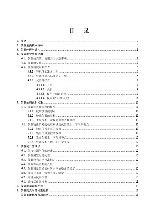
目录
1、简介 ............................................................................................................................................................. 2 2、仪器主要技术指标 ..................................................................................................................................... 2 3、仪器外形与结构 ......................................................................................................................................... 3 4、仪器的安装和使用 ..................................................................................................................................... 3
DH-2100 型电化学微量氧分析仪设计为在线连续工作或间断工作方式,采用高亮度 LED 数字显示氧含量,清晰直观,可视距离远。仪器可按现场工艺要求,可任意设定待 测气体氧量的上、下限报警控制点。当氧量超限时,仪器发出声光报警和输出开关信号, 为闭环控制提供方便。仪器设有 4~20mA 电流信号输出及 RS-232 通讯口,可与计算机 连接,进行数据的传-2100 型 电化学微量氧分析仪 使用说明书
HF240_90中文说明书(DOC)

二氧化碳培养箱H F90H F240使用技术说明书没有Heal Force的同意,不得以任何名义重新印制或散播任何关于本手册的内容,包括图片和音像品。
设备操作者可以复制这本操作手册的一些章节,但只能内部使用,比如,指导使用者如何处理突发事件。
在手册的目录里已经很清楚的标明这些章节的所在。
对于用户没有根据手册所声明的“仪器使用环境”而造成的任何仪器的损坏,Heal Force没有义务和责任对此负责。
Heal Force可以在没有适当通知的情况下,有权在任何时间对操作手册的内容进行修改。
环境要求* 室内使用* 可以工作于海拔0至2000米之间.* 当仪器工作在37℃,环境温度必须是18℃--30℃* 当温度超过30℃,最大相对湿度80%* 提供的主电源允许的波动范围可以是正常电压的±10%。
* 电源瞬间过压为II级* 污染等级为二度.* 室内必须安装有足够的通风设备* 安装表面必须是固定、水平以及不可燃烧的* 设备避免阳光直射* 设备旁边没有发热源安全提示* 第一次使用本机器,请仔细阅读本手册!* CO2培养箱只能由经过培训和授权的人员操作* 设备的维护只能由Heal Force或者Heal Force授权的代理商来完成*有可能燃烧或有潜在爆炸的组织、材料或液体物质,它们所散发出的蒸汽或是爆炸物的碎片可能释放有毒的物质,这些是不可以使用的!* CO2进气时的压力可以调节在0.8-1 bar 的范围内,并且不可更改。
* CO2是一种可能对人的身体健康造成危害。
* 只有合格的维修人员使用适当的工具才可以对培养箱的进气管和气体压缩容器,气体瓶或者存放有CO2的系统进行操作。
各警告标贴说明:注意:在使用仪器前,请仔细阅读使用技术说明书!注意:高温界面,当心烫伤!注意:小心玻璃!注意:高压危险!注意:主电源保险丝!保护用接地标志!HF90与HF240二氧化碳培养箱简明操作说明仪器出厂设置:温度---37.0℃, %CO2---0 %新机器使用前请先执行90℃湿热消毒(参阅Page23),然后再按照以下程序操作:1.打开外门和玻璃门, 向水池中注入蒸馏水(3L), 关门2.将仪器的通气接口连于CO2气源3.将仪器接通电源,开机4.仪器将自动执行常规检测功能, 此时,〖%CO2〗窗口及〖℃〗窗口均显示〖888〗及软件版本号。
美国CP2100系列AC DC电流探头用户手册说明书
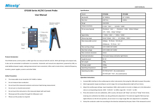
USER MANUALCP2100 Series AC/DC Current ProbeUser ManualProduct IntroductionThe CP2100 series current probe is a BNC type that can measure both DC and AC. With split design and compact look, it also can be connected to multimeters via connector. Automatic and manual zero adjustment, powered by USB, no need additional power supply, making measurement more convenient, often used in motor drives, industrial frequency, inverters, power supplies, avionics and other fields.Safety Precautions➢The measurable circuit should be CAT II 600V or below➢Do not measure bare conductors➢Do not touch the measured conductor and sensor head during measurement➢Do not use in a humid environment➢Do not touch the instrument or the measured object with wet hands➢Please ground this product through the USB power cord➢Please use this product as required SpecificationsOperation Instructions1.Connect BNC interface to the oscilloscope (or other instruments), then plug the USB cable to power the probe;2.Select appropriate range according to current range, the corresponding button light will turn Green;3.Adjust the oscilloscope settings: Input impedance 1MΩ; select probe to Current or display as A; Set attenuationratio on corresponding channel, 100A(0.01V/A)to 100X, range 10A(0.1V/A)to 10X;4.Press Zero button to do zero calibration, after success, the buzzer will “beep” one time; if “beep” three times,meaning zero calibration has failed; can also go Manual to adjustment. The external magnetic field may have slight influence on the DC zero position, do not move it in a large range after zero adjustment is completed; 5.Clamp the conductor under test according to the direction indicated by the jaws. Note: If the measured currentUSER MANUALflows in the opposite direction, the output will be negative;6.Adjust the oscilloscope to get the best waveform;Note: When the current exceeds the range, the buzzer will beep for a long time and the button light will flash. ReferencesF1. - Maximum current vs Frequency curve F2 - Amplitude-frequency characteristic curve - CP2100A F3 - Amplitude-frequency characteristic curve-CP2100B F4 - DC signal linearity (0.01V/A)MaintenanceDuring the warranty period of the product (one-year) and under normal use, the company will be responsible for free repairs due to fault caused by the quality of the product itself, and the product must not be disassembled or repaired without Micsig permission. Please keep the product dry, clean and tidy. If there is dirt, use a soft cloth or sponge with alcohol to wipe off. Do not use water. In order to ensure the performance of the product, it is recommended to check or calibrate once a year.StatementThe information provided in this document is subject to change in future versions without notice. In addition, to the maximum extent permitted by applicable laws, Micsig does not provide any express or implied warranty for this manual and any information contained in it.Shenzhen Micsig Instruments Co., Ltd.Tel:+86 (0)755 88600880 Email:****************Add: A106, Huafeng International Robot Industrial Park,Bao’An district, Shenzhen, 518126, Guanddong, China。
中科科仪产品资料

<100Pa 27000 <5 精密陶瓷轴承 (需通保护气体) KF40(DN40 KF) DN160 LF、DN160 CF ≤0.1
4-8 ≤25 ≤100 5-40 150 内径Φ10 直插自密封 竖直±5° 29
10
真空获得产品 FF-160/700型脂润滑复合分子泵
FF-0/00型进气口法兰为: DN0LF、DN0CF
真空获得产品 FF15型分子泵
FF型进口法兰为:KF0
FF15型分子泵安装尺寸图(单位:mm)
FF15型抽速曲线
北京中科科仪技术发展有限责任公司
KYKY TECHNOLOGY DEVELOPMENT LTD.
FF15型分子泵技术性能
型号 抽气速率(L/S) 极限压强(Pa)
N2 压缩比(Max)
FF-100/110 110
N2: 108; H2: 5×10² ≤6×10⁻⁶ (DN100 LF) ≤6×10⁻⁷ (DN100 CF)
KiloVault 2100 PLC 2100WH 12V高级AGM电池安装及用户手册(修订版1.0

KiloVault® 2100 PLC 2100WH 12V Advanced AGM BatteryInstallation and User Manual*WARNING High Voltage Risk of Personal Injury or Death**As is the case with all batteries, the risk of shock is present. When handling batteries, use protective measures including, but not limited to, safety glasses, insulated gloves, and protective footwear.When working with or installing batteries, use electrically insulated gloves and tools. Remove personal metal items such as watches, rings, bracelets, etc.The information included in this manual is accurate at the time of publication. However, this manual is subject to change without prior notice as we continuously improve our products. Additionally, the illustrations in this manual are for demonstration only and are intended to help explain the KiloVault® 2100 PLC system concepts and installation instructions. Details may vary slightly depending upon the market region and the product version.Please note: If this unit is installed by someone other than the end-user, the installer must explain the contents of this installation and user’s manual to the end-user.Contents1.Safety Information (4)1.1.Symbols Used in this Manual (4)1.2.General Safety Precautions and Instructions (4)1.3.Battery Handling Guide (6)1.3.1.Transportation (6)1.3.2.Storage (6)1.3.3.Response to Emergency Situations (6)1.3.4.Qualified Personnel (6)2.Overview (8)2.1.Features (8)2.2.Product Technology (8)3.Specifications (9)4.Operation (12)4.1.Charging (12)4.1.1.Charging Characteristics (12)4.1.2.Temperature Compensation (13)4.2.Discharging (13)4.2.1.Discharge Characteristics (13)4.2.2.Discharge Temperature Characteristics (14)4.2.3.Self-Discharge (14)4.2.4.Recharging (15)4.2.5.Open-Circuit Voltage (OCV) vs. State of Charge (SoC) (15)4.3.Cycle Life (16)5.Environmental Protection (17)5.1.Toxic and Poison Checklist (17)5.2.Recycling (17)6.Technical Support (18)6.1.Downloads (18)6.2.Documentation (18)6.3.Contact Us (18)1.Safety Information1.1.Symbols Used in this ManualIt is essential to read, understand, and follow these instructions prior to installing or operating KiloVault® batteries.Warning:This is a hazardous situation which, if not avoided, could result in serious injury ordeath.Warning:Do not place or install near flammable or explosive materials.Warning:Install the KiloVault® 2100 PLC out of the reach of children and animals.Warning:The KiloVault® 2100 PLC is heavy, over 127 lb (58 kg), and may cause serious backinjury. Lift with multiple people and lifting equipment rated to lift and support at least140 lb.Warning:Do not dispose of this product with household waste.Caution:Risk of electric shock.Attention:Disconnect the battery before carrying out maintenance or repair.Attention:Read this instruction manual before installing and operating the battery.Note:Indicates points of particular emphasis that make operation more efficient orconvenient.Recyclable:Please contact KiloVault® for recycling instructions.1.2.General Safety Precautions and InstructionsWarning:Failure to follow the instructions in this manual may result in serious injury or death.Caution:Risk of electric shock.Warning:Do not place or install near flammable or explosive materials.Warning:Install the KiloVault® 2100 PLC out of the reach of children and animals.Warning:The KiloVault® 2100 PLC is heavy, over 127 lb (58 kg), and may cause serious backinjury. Lift with multiple people and lifting equipment rated to lift and support atleast 140 lb.Warning:Do not dispose of this product with household waste.Attention:Read this instruction manual before installing and operating the battery.∙Do not attempt to use any battery that appears damaged during shipment or otherwise.∙Do not submerge the KiloVault® 2100 PLC. This could cause injury and will void your warranty.∙Do not attempt to disassemble the KiloVault® 2100 PLC. Its components are not user serviceable. This could cause personal injury and will void your warranty.∙To avoid the risk of shock or fire, ensure all wire is properly sized and in good condition.∙Do not impact, pull, drag, or step on the KiloVault® 2100 PLC.∙Verify all equipment be connected to the KiloVault® 2100 PLC is off before making connections.∙ A small risk of spark does exist while making connections. Ensure the area is free of explosive gasses and liquids and is not installed in confined areas. This includes flammable fuel powered machinery, holding tanks, pipe fittings, and connectors.∙Respiratory irritation may be caused if the KiloVault® 2100 PLC is punctured or cracked.∙Skin contact with a punctured or otherwise open battery can cause irritation.∙If the KiloVault® 2100 PLC becomes punctured or cracked, use appropriate respiratory and hand protection.∙High voltage battery connections (configurations of greater than 36V DC nominal) can be dangerous in any DC system. A 48V nominal battery bank can have 60VDC at the terminals when fully charged!∙ DC voltages over 52V can stop the human adult heart; please be careful and wear insulated gloves.1.3.Battery Handling GuideIn addition to the General Safety Precautions and Instructions, the following guidelines should be observed when handling the KiloVault® 2100 PLC.1.3.1.Transportation∙Because the KiloVault® 2100 PLC weighs over 127 lb, it should be moved with the help of multiple people and moving/lifting equipment rated over 140 lb.∙Do not drop the KiloVault® 2100 PLC.∙If you are transporting KiloVault® 2100 PLC batteries while they are still in the packing crate, do not stack them more than 5 layers high.∙Only transport the KiloVault® 2100 PLC face up.∙Check immediately after transporting.∙If the KiloVault® 2100 PLC is damaged in any way, do not use it; contact KiloVault immediately.1.3.2.StorageIn addition to the General Safety Precautions and Instructions, the following guidelines should be observed when storing the KiloVault® 2100 PLC.∙Store in a clean, dry, shaded, and well ventilated area, at a temperature between 15 °C and35 °C.∙Charge to at least 70% (the state of charge upon delivery) before storage.∙Store no longer than 6 months.∙Repeated (100%) discharges will decrease battery capacity.∙Fully charge the battery within 15 days of a deep discharge of 90% or more.∙Do not drop, stack, or turn upside down.∙Store away from children and animals.Keep your batteries away from heaters and organic solvents. An increased storage temperature results in an increased self-discharge rate, so store them in a cool dry environment.1.3.3.Response to Emergency SituationsThe KiloVault® 2100 PLC is designed to prevent hazards resulting from failures; however, no battery system is 100% safe, and KiloVault, LLC cannot guarantee its absolute safety.In the unlikely event of a fire, if possible, first shut off the source of the electricity. We recommend having a fire extinguisher in close proximity of your power generating equipment. Class ABC extinguishers are easily obtainable and are best suited for multipurpose fire types such as wood, flammable liquids, and electrical appliances.1.3.4.Qualified PersonnelThis guide, and the tasks and procedures described in this manual, are intended for use by qualified personnel only. Only qualified personnel shall install, operate, overhaul, or maintain the KiloVault® 2100 PLC. During maintenance or overhaul, at least two people (equipped withprotective measures, including but not limited to, safety glasses, insulated gloves, and safety shoes) must be present.Qualified personnel are defined as being a trained and locally certified electrician or installer who has of the following knowledge, skills, and experience:∙Functional principles and operation of on-grid and off-grid (backup) electrical systems∙Dangers and risks associated with installing and using electrical devices and acceptable mitigation methods∙Installation of electrical devices∙Knowledge of and adherence to the information in this guide, to all applicable safety precautions, and to electrical industry best practicesWhen working with any battery system, ensure you have the necessary tools and safety equipment, including but not limited to:∙Insulated tools∙Rubber apron and gloves∙Face protection/face shield∙Safety goggles∙Fire extinguisher∙Emergency eyewash and shower, if available∙Acid spill cleanup kitUse the following safety precautions:∙Pay attention to electrical warning symbols to avoid serious injury or death caused by electrical shock or burns.∙Remove all rings and jewelry while working on batteries.∙Multi-cell battery systems can attain high voltage and/or currents. Do NOT touch uninsulated batteries, connectors, or terminals. To prevent serious electrical burns and shock, use EXTREME CAUTION when working with DC Battery system.∙Always wear protective clothing.∙Protect your eyes and any exposed skin.∙Use non-conductive or insulated tools when working with ANY battery system.∙All installation tools should be adequately covered with vinyl electrical tape or suitable non-conductive material to minimize the possibility of shorting across connections.∙Never lay tools or other conductive objects on the battery.∙Do not short circuit these batteries.∙Do NOT throw away these batteries, they are recyclable.8 of 19Revision 1.052.Overview2.1.Features∙Maintenance Free: No watering, 2-year shelf life, and low self-discharge rate∙Maximized Cycle Life: Affordable high performance with 3000 Cycles at 50% depth of discharge (DoD)∙Super-Fast Charging: High charge rates allow the KiloVault® 2100 PLC to go from 50% up to 90% state of charge in under an hour∙Exceptional Value: Less cost per kWh cycle than other lead acid batteries∙Advanced Technology: KiloVault® 2100 PLC high power, energy dense batteries have a specially formulated carbon additive that enhances the overall battery life∙Partial State of Charge (PSoC) Applications: Pure lead + carbon = greater cycle life in both PSoC and non-PSoC off-grid operations∙ 5 Year Limited WarrantyOur newest member of the KiloVault family is not a sibling but a cousin! The 2100 KiloVault® 2100 PLC is a pure lead carbon sealed AGM deep cycle solar battery. It is a cost-effective, maintenance-free battery offering superior performance in PSoC applications. These batteries are designed for residential or light commercial off-grid, backup, or self-consumption applications.The KiloVault 2100 PLC is a Premium Pure Lead Punched Grid Cycling Battery, with excellent anti-corrosion performance, and low float current, greatly extending calendar and cyclic life. The KiloVault 2100 PLC has advanced Pure Lead + Carbon, which offers superior performance in PSoC applications. Other lead acid chemistry batteries sulfate and lose overall performance when left in a low state of charge over time. Solar energy storage could be discharged, followed by an extended period of cloudy days, reducing the charging performance of the solar panel, and therefore not charging the energy storage battery for days. With the KiloVault 2100 PLC, this is not a problem.It doesn’t stop there. The KiloVault 2100 PLC has strong high temperature ABS/Polycarbonate Flame Retardant jars to UL94V-0 and <28% LOI (limiting Oxygen Index). Plate design provides consistent, low internal resistance, and larger reaction surface. The large top posts allow low connector resistance, and the convenient Front Terminal Adapter allows fast and easy installation, zero overhead space required, and easier maintenance records documentation. 2.2.Product Technology∙Valve Regulated Lead Acid (VRLA) maintenance free∙Pure lead punched grid plate with low self-discharge∙Excellent Charging Acceptance with High Charging Efficiency∙UL94V-0 ABS+PC enclosure∙Excellent PSoC Cycle Performance∙Super-Fast Charging: from 50% up to 90% state of charge in under an hour∙Integrated valve design controlling water loss, acid fog, and improved explosion resistanceSpecifications3.Figure 1: Physical DimensionsFigure 2: Battery TerminalsFigure 3: Terminal Interconnects4.Operation4.1.ChargingKiloVault 2100 PLC batteries are usually charged using a three-stage charging cycle: bulk, absorption, and float stages. Bulk is a constant-current stage. The purpose of the bulk stage is to raise the battery voltage to a relatively high level with an initial fast charge. Absorption is a constant voltage stage. It is established upon reaching the absorb voltage settings. The battery is considered to be full when the following conditions are met: The charge current must taper down to 1% of the total battery amp-hours while maintaining the absorption voltage. The charger can then exit absorption and then enter the float stage. The float stage is a maintenance stage which ensures the battery remains fully charged.4.1.1.Charging CharacteristicsNot all chargers are designed or programmed the same way. Please use the following settings for chargers, inverter/chargers, and charge controllers.∙Bulk / Absorption: 14.1VDC∙Equalize (rarely needed): 14.1VDC – see footnote2∙Float: 13.62VDCFigure 4: Constant Current Charge2Equalization is only recommended if: the battery is stored for more than three months, if it is floated for more than one year, or if is discharged more than 80%.Figure 5: Constant Voltage Charge4.1.2.Temperature CompensationTo achieve longer battery life, compensate for temperatures above or below 77°F (25°C). For KiloVault 2100 PLC batteries we recommend -30mV/°C (-5mV/cell/°C).4.2.DischargingBattery capacity depends on the discharge current or discharge rate. If the discharge current is smaller, the discharge capacity will be larger. If the discharge current is larger, the discharge capacity will be smaller.4.2.1.Discharge CharacteristicsThe final voltage is based on the discharge current and the minimum allowed by the system setup.Figure 6: Discharge Curves Given Different Discharge Currents4.2.2.Discharge Temperature CharacteristicsBattery capacity increases with the temperature. The size of the effect the temperature has is affected by the discharge current/discharge rate. This effect becomes more obvious when the battery is discharged at a larger current.Figure 7: Temperature Effects on Capacity Discharge Rates4.2.3.Self-DischargeStored batteries will need to be recharged to recover from self-discharge. The rate of self-discharge increases as the temperature increases.Figure 8: Self-Discharge Curves4.2.4.RechargingGenerally speaking, lead sulfate will be produced on the battery negative plate when they arestored for a long time. KiloVault® 2100 PLC batteries can be stored for up to 24 months. Because lead sulfate is an electrical insulator, it negatively affects the performance of the battery. Werecommend the following recharge schedule based on storage temperatures.If a battery is stored under 68°F (20°C), it should be recharged every 9 months, at a constant13.38V to 13.62V, current limit 0.25C10 for 2 to 3 days.If it is stored between 68°F and 86°F (20°C to 30°C), it should be recharged every 6 months at13.8V to 14.4V, current limit 0.25C10 for 10 to 16 hours.If it is stored between 86°F and 104°F (30°C to 40°C), it should be recharged every 3 months at13.8V to 14.4V (temperature compensated -3mV/°C), current limit 0.1C10 for 8 hours or 0.05 C10 for 16 hours.4.2.5.Open-Circuit Voltage (OCV) vs. State of Charge (SoC)The open-circuit voltage of lead acid batteries varies with the specific gravity of the electrolyte.While discharging, the specific gravity of the electrolyte changes greatly but cannot be measured in a closed battery, so the open-circuit voltage is measured and the approximate residual capacity is calculated.Figure 9: OCV/Cell vs. SoC4.3.Cycle LifeThe cycle service life of the battery is related to the frequency of discharge, the depth of discharge, the floating voltage, and the working environment. Total cycle life decreases with increasing temperatures and depths of discharge.Figure 10: Approximate Total Cycle Count vs. DoD5.Environmental ProtectionToxic and Poison Checklist5.1.RecyclingThis battery cannot be disposed of with other waste. In order to prevent the release of potentially hazardous substances, risks to the environment, and risks to human health from improper hazardous waste disposal, do not throw away this battery in the general waste stream. Please recycle it.In order to recycle this battery, please use your local recycling system or contact your waste management authority for the proper lead-acid battery recycling procedures in your area.6.Technical Support6.1.DownloadsDownloads will be made available on the KiloVault website.6.2.DocumentationDocumentation can be downloaded from the KiloVault website: https:/// 6.3.Contact UsEmail: *******************************Phone: +1 (877) 878-4060KiloVault, LLC330 Codman Hill RoadBoxborough, MA 01719。
赛默飞世尔科技Orion 2100系列抓斗采样器安装指南说明书
Thermo Scientific Orion 2100 Series Grab Sampler Installation Guide for the 2111XP Sodium AnalyzerROSS and the COIL trade dress are trademarks of Thermo Fisher Scientific Inc. U.S. patent 6,793,787. AQUAfast, Cahn, ionplus, KNIpHE, No Cal, ORION, perpHect, PerpHecT, PerpHecTion, pHISA, pHuture,Pure Water, Sage, Sensing the Future, SensorLink, ROSS, ROSS Ultra, Sure-Flow, Titrator PLUS and TURBO2 are registered trademarks of Thermo Fisher.1-888-pHAX-ION, A+, All in One, Aplus, AQUAsnap, AssuredAccuracy, AUTO-BAR, AUTO-CAL, AUTO DISPENSER, Auto-ID, AUTO-LOG, AUTO-READ, AUTO-STIR, Auto-T est, BOD AutoEZ, Cable-Free, CERTI-CAL, CISA, DataCOLLECT, DataPLUS, digital LogR, DirectCal, DuraProbe, Environmental Product Authority, Extra Easy/Extra Value, FAST QC, GAP, GLPcal, GLPcheck, GLPdoc, ISEasy, KAP, LabConnect, LogR, Low Maintenance T riode, Minimum Stir Requirement, MSR, NISS, One-T ouch, One-T ouch Calibration,One-Touch Measurement, Optimum Results, Orion Star, Pentrode, pHuture MMS, pHuture Pentrode, pHuture Quatrode, pHuture T riode, Quatrode, QuiKcheK, rf link, ROSS Resolution, SAOB, SMART AVERAGING, Smart CheK, SMART STABILITY, Stacked, Star Navigator 21, Stat Face, The Enhanced Lab, ThermaSense, T riode, TRIUMpH, Unbreakable pH, Universal Access are trademarks of Thermo Fisher.© 2009 Thermo Fisher Scientific Inc. All rights reserved. All trademarks are the property of Thermo Fisher Scientific Inc. and its subsidiaries.The specifications, descriptions, drawings, ordering information and part numbers within this document are subject to change without notice.This publication supersedes all previous publications on this subject.Table of ContentsGrab Sampler nstallation . . . . . . . . . . . . . . . . . . . . . . . . . . . . . . . . . . . . . . . . .1General Information . . . . . . . . . . . . . . . . . . . . . . . . . . . . . . . . . . . . . . . . .1Air Pump Shutoff and Start-up Procedure . . . . . . . . . . . . . . . . . . . . . . . . .1Required Tools . . . . . . . . . . . . . . . . . . . . . . . . . . . . . . . . . . . . . . . . . . . . .2Grab Sampler Installation Procedure . . . . . . . . . . . . . . . . . . . . . . . . . . . . .3Grab Sampler Measurement . . . . . . . . . . . . . . . . . . . . . . . . . . . . . . . . . . . . .11Grab Sampler Measurement Procedure . . . . . . . . . . . . . . . . . . . . . . . . . .11Returning the Analyzer to Process Sample Measurement . . . . . . . . . . . . .12Customer Services . . . . . . . . . . . . . . . . . . . . . . . . . . . . . . . . . . . . . . . . . . . . . .13Servicing the Particulate Filter . . . . . . . . . . . . . . . . . . . . . . . . . . . . . . . . .13Assistance . . . . . . . . . . . . . . . . . . . . . . . . . . . . . . . . . . . . . . . . . . . . . . . .14Warranty . . . . . . . . . . . . . . . . . . . . . . . . . . . . . . . . . . . . . . . . . . . . . . . . .14Ordering Information . . . . . . . . . . . . . . . . . . . . . . . . . . . . . . . . . . . . . . .14Chapter 1Chapter 3Chapter 2Chapter 1 Grab Sampler nstallationThe grab sampler allows for rapid sample measurement where no online instrumentation is present and provides troubleshooting to validate readings without disturbing process operations . Operators can temporarily interrupt the flow of process sample to the 2111XP sodium analyzer and substitute it for a sample coming from the grab sampler . In this way, samples from other parts of the plant or validation and calibration standards can be analyzed .Warning: T urn off the air pump prior to removing reagent bottle . The air pump will spatter caustic reagent outward as bottle is removed . Wear rubber gloves and safety goggles to avoid possible injury from reagent residues in the system .1 . T o access the air pump setting, press .2 . Press / to scroll though the setup parameters until TEST appears in marquee window .3 . Press to access the TEST menu .4 . Press / to scroll through the TEST menu until AIr appears in the main display .5 . Press .6 . Press / to toggle between On and OFF settings for the air pump power . To turn the air pump off, select the OFF setting . T o turn the air pump on, select the On setting . Changing the air pump setting to On or OFF will be indicated by a click sound .7 . Pressto accept the setting and return to the TEST menu .8 . Press to return to the measure mode .General nformation Air Pump Shutoff and Start-up ProcedureFigure 12111XP Analyzer ComponentsScrolling MarqueeLCD DisplayMounting HoleKeypad Flow Cell ReservoirSiphon TubeFlow Cell BlockInlet ValveReagent Bottle Adapter Assembly Pressure Regulator Flow MeterCalibration PortReference Filling Solution Restructor Tube AssemblyAir PumpBypass/Needle ValveInlet FilterReagent ManifoldDiverter Valve Diffusion Tubing AssemblyReagent Bottle• Phillips head screwdriver• Adjustable wrench• T ubing cutterRequired ToolsWarning: The reagent is hazardous . Use protective glasses and gloves whenworking with the reagent . Refer to the reagent bottle label and MSDS for precautions and work in a well ventilated area .1 . Shut down the analyzer .a . T urn off the air pump . See the Air Pump Shutoff and Start-up Procedure section .b . Disconnect the power to the analyzer .c . S hut off the process pressure to the analyzer . The process sample supply must be shut off upstream of the analyzer . Do not just close the inlet valve on the analyzer .2 . Remove the reagent bottle from the analyzer and set it aside .a . L oosen the thumb nut that secures the bottle to the manifold block and slide the bottle assembly off the mounting stud .b . N ote that some process sample may drip out of the manifold when you remove the reagent bottle .c . S et the reagent bottle aside for later use . The reagent bottle should be stored in a well ventilated area .3 . Disconnect the process sample feed line to the inlet valve on the analyzer .4 . Remove the regulator bracket .a . L oosen and remove the ring nut that holds the pressure regulator to the regulator bracket .b . R emove the two screws that secure the bracket to the analyzer panel .c . S lide the bracket off the regulator . The regulator will be held in position by the system plumbing . d . D o not discard the loose components – they will be reassembled later during the installation process .5 . Disconnect the tube at the inlet of the pressure regulator . a . U nscrew the ferrule nut on the pressure regulator inlet .Grab Sampler nstallation Procedure6 . Remove the inlet valve and bypass valve assemblies from the analyzer .a . U nscrew the ferrule nut on the pressure regulator inlet anddisconnect the sample tube .b . R emove the two screws that secure the inlet valve bracket to theanalyzer panel .c . I f the unit includes a bracket connected to the bypass needle valve,remove the two screws that secure the bracket to the analyzer panel .d . R emove the four screws that secure the bypass valve and particulatefilter to the analyzer panel .e . R emove the inlet valve and bypass valve assemblies from theanalyzer panel .7 . Assemble the new valve module to the analyzer . See Figure 2 .a . P lace the valve module in position on the analyzer panel and secureit with four mounting screws .b . S lide the supplied ferrule nut onto the free end of the black tubingon the new valve assembly .c . I nsert the free end of the black tubing into the inlet port on thepressure regulator . Verify that the tubing fits properly – it shouldbottom out against a stop in the regulator inlet without bucklingor kinking . T rim the tubing if necessary . Tighten the ferrule nut tosecure the tube to the regulator .d . C onnect the inlet line to the empty leg of the quick-connect elbowfitting on the 2-way valve included in the valve module . Insert theprocess tubing until it bottoms out against a stop in the fitting .8 . Re-assemble the regulator bracket .a . S lide the bracket over the pressure regulator .b . S ecure the bracket to the analyzer panel with two mounting screws .c . R eplace the ring nut onto the pressure regulator and tighten itagainst the regulator bracket .Figure 2 2111XP Grab Sampler Valve Module Mounting HolesGrab Sampler Mounting HolesGrab SamplerMounting BracketFigure 32111XP Grab Sampler Mounting Bracket Installation9 . Assemble the grab sampler mounting bracket to the analyzer panel .See Figure 3 .a . D isassemble the restrictor tubing from the flow meter . Loosen thecable clip that secures the restrictor tubing to the analyzer panel andloosen the compression fitting that secures the restrictor tubing tothe top of the flow meter .b . R emove the large cable clamp that secures the various drain lines tothe analyzer panel . Remove the mounting screw and set the clampaside for later use .c . U nscrew the two bolts that secure the flow cell assembly to theanalyzer panel . Support the flow cell assembly so that it does notfall .d . P lace the grab sampler mounting bracket in position between theanalyzer panel and the flow cell assembly . The mounting slots onthe bracket should align with the mounting holes on the flow cell .e . S ecure the flow cell assembly and mounting bracket by re-assembling the two mounting bolts .f . F eed the restrictor tubing through the grab sampler mountingbracket . Re-assemble the free end of the restrictor tubing to the flowmeter and secure the tubing to the analyzer panel with the smallcable clip .g . T hread a mounting screw into the lower-right slot in the grabsampler mounting bracket and secure it to the analyzer panel .h . R e-assemble the large cable clamp through the lower-left slot on thegrab sampler mounting bracket .i . R e-secure the various drain lines to the large cable clamp .j . A ssemble the clear drain line included with the valve module . Insert one end of the tube into the bypass elbow fitting and tighten thecompression nut . Route the tube under the reagent bottle manifold,through the large cable clamp, and down to the system drain .10 . Mount the grab sampler assembly to the analyzer .a . L oosely assemble four #10-24 mounting screws to the threadedholes in the grab sampler mounting bracket .b . R emove the sample bottle from the grab sampler and fit the unitonto the mounting screws on the bracket . Tighten the screws tosecure the unit .c . S nap the sample bottle back into the sampler housing .d . R oute the sample line from the bottle under the reagent bottlemanifold and over to the compression-style elbow connected to the3-way valve on the new valve module . Tighten the ferrule nut onthe elbow to secure the tube .e . R oute the loose tube from the bottom right of the grab samplemodule to the system drain .f . C onnect the power supply to the power jack on the grab sampler .11 . Re-assemble the reagent bottle to the analyzer .a . C heck to be sure that none of the three O-rings on the reagentmanifold block have been lost .b . A ssemble the reagent bottle onto the mounting stud on themanifold block and secure it with the thumb nut .12 . Return the analyzer to service .a . R econnect the power to the analyzer .b . O pen the process sample line to the analyzer assembly .c . T urn on the air pump . See the Air Pump Shutoff and Start-upProcedure section .d . P lace the various valves in the process sample position . The 2-wayinlet valve should be rotated counterclockwise so that it points tothe left . The 3-way sample valve should be rotated counterclockwiseso that it points to the right .e . A djust the pressure regulator to maintain the correct process flow .f . A djust the bypass valve to deliver the desired amount of bypass flowto drain .g . V erify that the various plumbing connections made during theinstallation are sealing properly . If a leak is detected, close the inletvalve and tighten the various fittings as needed .Figure 2111XP Grab SamplerComponentsFigure Components for Operating the Grab SamplerInlet Valve – ASample Valve – BParticulate Filter – CBypass Valve – DPressure Regulator Knob – EFlow Meter – F A B C D E FChapter 2 Grab Sampler MeasurementRefer to Figure 5 for the location of the components identified in the following procedure .1 . Verify that the system is configured to take a standard measurement . a . T he diverter valve on the flow cell should be pulled out .2 . Prepare the sample bottle .a . R inse the bottle with deionized water and then with a small amount of the desired sample . Discard the rinse water .3 . Load the sample .a . F ill the bottle with the sample .b . R eplace the cover on the bottle and load the bottle into the grab sampler .4 . Start the grab sampler .a . T urn the grab sampler power switch on . b . A llow the pump to run for 10 to 30 seconds to build pressure .5 . T urn the sample valve (B ) to the grab sample position .a . T urn the knob on the sample valve clockwise until it points to the left . b . T he process stream will still be open to the particulate filter (C ) and will continue to flow through the bypass valve (D ) . This will not interfere with the grab sample measurement and insures that the process stream is fresh when the grab sample measurement is complete .c . A djust the pressure regulator if required (see step 6) .6 . Adjust the knob on the pressure regulator (E ) so the ball in the flow meter (F ) indicates the correct flow rate . The flow rate should be 40 mL/minute for the Ammonia and DIPA Application Packages and 25 mL/minute for the Cation/High Acid Application Package . a . P ull the knob out to unlock the setting and adjust the flow rate .Grab Sampler Measurement Procedureb . T urn the knob clockwise to increase the flow rate .c . T urn the knob counterclockwise to decrease the flow rate .d . P ush the knob in to lock the setting .7 . Wait for the system to stabilize before taking the grab sample measurement .a . T he system will take time to flush any remaining process sample before the grab sample measurement stabilizes . The specific time required will depend on the sodium content of the residual process stream and the grab sample .Refer to Figure 5 for the location of the components identified in the following procedure .1 . After the grab sample measurement is complete, return the sample valve (B ) to the process setting .a . T urn the knob on the sample valve counterclockwise until it points to the right . b . A djust the pressure regulator if required (see step 2) .2 . Adjust the knob on the pressure regulator (E ) so the ball in the flow meter (F ) indicates the correct flow rate . The flow rate should be 40 mL/minute for the Ammonia and DIPA Application Packages and 25 mL/minute for the Cation/High Acid Application Package .a . P ull the knob out to unlock the setting and adjust the flow rate .b . T urn the knob clockwise to increase the flow rate .c . T urn the knob counterclockwise to decrease the flow rate .d . P ush the knob in to lock the setting .3 . Vent any residual pressure in the grab sampler system .a . P ress the pressure relief button on the grab sampler .4 . Rinse out the sample bottle .a . R emove the sample bottle from the system and discard any remaining sample .b . R inse the inside of the bottle with clean, deionized water and allow it to dry .c . R eplace the bottle in the grab sampler .Returning the Analyzer to Process Sample MeasurementChapter 3 Customer ServicesRefer to Figure 5 for the location of the components identified in the following procedure .1 . Close the inlet valve (A ) to shut-off process flow to the system .a . T urn the knob on the inlet valve clockwise until it points upward .2 . Remove the cap on the particulate filter .a . L oosen the panel nut on the bypass valve (D ) .b . U nscrew the cap on the particulate filter (C ) .c . S lide the bypass valve up into the top of its mounting slot and pivot it to allow access to the interior of the particulate filter .3 . Service the filter element .a . R emove the filter element from the particulate filter (C ) .b . C lean the filter element . The cleaning agent should be compatible with the 316 stainless steel filter element .4 . Replace the filter element in the filter housing .a . I nstall the filter element with the open end facing down .5 . Re-assemble the particulate filter cap (C ) .a . S crew the filter cap back onto the filter body .b . T ighten the panel nut on the bypass valve (D ) .6 . Re-open the inlet valve (A ) to restore process flow to the system .a . T urn the knob on the inlet valve counterclockwise until it points to the left .Servicing the Particulate FilterAfter troubleshooting all components of your measurement system, contact Technical Support . Within the United States call 1 .800 .225 .1480 and outside the United States call 978 .232 .6000 or fax 978 .232 .6031 . In Europe, the Middle East and Africa, contact your local authorized dealer . For the most current contact information, visit www .thermo .com/contactwater .For the latest application and technical resources for Thermo Scientific Orion products, visit www .thermo .com/waterapps .For the most current warranty information, visitwww .thermo .com/processwater .21GRABXP Grab sampler / FAST QC ™ upgrade module to fit existing 2111XP , 2111XPEN, 2110XP , 2110XPEN, 2117XP , 2117XPEN, 2120XP and 2120XPEN analyzers(Not currently available for use with 2109XP or 2109XPEN fluoride analyzers)21GRABLLLow level sodium grab sampler / FAST QC ™ upgrade module to fit existing 2111LL and 2111LLEN analyzers 21GRBTReplacement bottle for 2100 series grab sampler 21GRPAAir pump replacement kit for 2100 series grab sampler 21GRFK Fittings kit for 2100 series grab samplerAssistance Warranty Ordering nformationProcess Water InstrumentsNorth America 166 Cummings Center Beverly, MA 01915 USA Toll Free: 1-800-225-1480 Tel: 1-978-232-6000 Dom. Fax: 1-978-232-6015 Int’l Fax: 978-232-6031Europe P .O. Box 254, 3860 AG Nijkerk Wallerstraat 125K, 3862 CN Nijkerk, Netherlands Tel: (31) 033-2463887 Fax: (31) 033-2460832Asia Pacific Blk 55, Ayer Rajah Crescent #04-16/24, Singapore 139949 Tel: 65-6778-6876 Fax: 65-6773-0836/processwater© 2009 Thermo Fisher Scientific Inc. All rights reserved.。
华创气体仪表资料.doc

北京华创凯达科技有限公司Beijing Huachuangkaida Technology co.,LTD气体仪表技术资料北京华创凯达科技有限公司二零壹零年公司名称:北京华创凯达科技有限公司目录HC®K960便携式氢气纯度分析仪HC®D500便携式露点仪HC®D30精密露点仪HC®N700便携式氮气纯度分析仪HC®P500便携式SF6纯度析仪HC®XH110便携式气体检测仪HC®K960C在线氢气分析仪HC®KG960便携式氢氧分析仪HCG210系列氧分析仪HC®D500C在线露点仪HC®D30C在线露点仪(冷镜式)HC®M600C在线氧气纯度监测仪HC®XH110C在线氢气检漏仪HC®XF110C在线SF6泄漏检测仪HC®M610C在线微量氧分析仪(氢中氧) HC®M620C在线氧中氢分析仪公司名称:北京华创凯达科技有限公司产品名称:便携式氢气纯度分析仪 产品型号: HCK960产品概述:便携式氢气纯度分析仪常用热导原理,全中文操作界面,不但可以监测发电机运行中的氢气纯度及制氢站正常运行下的氢气纯度,还可以监测发电机检修前后的停机和启机时的气体浓度.主要特点:● 不需要提前取样,直接携带到现场的取样处连接上导气管后即可进行测试。
● 仪器采用充电电池供电,体积小,重量轻,操作简单,反映速度,读数稳定。
● 仪器测试精度优于0 .15%,线性度好。
● 仪器充电后能够连续使用8个小时。
● 纯度检测传感器,具有温度补偿及恒温功能技术指标:测试范围 :空气中的H 2 含量(0%~100%)(同时可根据用户需求特定测量范围)空气中的CO 2 含量(0~100%) CO 2中的H 2含量(0~100%)测量精度:±0.1% 重 复 性:±0.1%存储容量:存储50条测量记录输出接口:USB1.1,直接与电脑相连接打印测试结果 显 示:超大液晶显示,图形菜单 环境温度:–30℃~60℃ 响应速度:<15S稳 压 阀:工作范围0~1MPa 工作压力:0~1Mpa单位地址: 北京市海淀区上地创业路8号群英科技园4号楼 邮编: 100085电 话************* 传真*************样气流量:20~200ml/min 额定功率:5W外形尺寸:258(长)×240(宽)×88(高)mm3 重 量:2.5kg附 件:内衬泡沫的便携式手提箱 选 配 :油过滤装置产品名称:便携式氢氧分析仪 产品型号: HCKG960同时检测氢气纯度以及氢气中的含氧量量程:H 2 90~100%;可选0~100%;精度±0.1%O 2 0~25%; 精度±0.25%H C G 210系列氧分析仪H C G 210系列便携式氧分析仪表能够测量从0.1ppm 到高浓度的氧,因而在气体制造和应用工业中被广泛使用。
凯尔贝类激光等离子电源HF440i中文手册

高压引弧的引弧板被放在等离子中.按下引弧按钮,开始引弧 。引弧结束后,高压开关自动关 闭。
位置 : 7.1 9/W a rnu ng , V o rsich t, V erb ot , G ebo t, Hinweis /War nun g ( o ran ge) / Ret tun g szeich en (gr ün)/B ren nerk op f nicht b er ühr en @ 0\m od_120 299 6 840 384 _ 19 .doc @ 36 75
警告 高压危险警告 电击会导致生命危险. 在任何维修或维护之前,请将开关关掉,并断开主电路。打开等离子机器,需要 资深电工来执行。
位置 : 7.1 2/S iche rh e it/W erk s tück ansc hli eße n und e rde n@ 0\m o d_1 200 05 2 757 236_19. doc @ 27 30
1. 操作工或维修人员在操作机器之前,必须熟悉这些标 示的意义.每个公司的公司安全手册都因该考虑这些 2.切割过程中产生的烟尘,灰尘,和气体对身体有害, 不能呼入体内.需要增加一个除尘设备 3. 穿防护衣 (头盔,焊接工人的防护罩,皮革围布,防护 手套,安全鞋). 防护衣要绝缘,干燥,防火。 4. 噪音对身体有害! 等离子切割过程中,需要带上护耳 设备. 等离子弧的辐射会导致眼痛或皮肤灼伤.保护眼睛 和皮肤是十分必要的。选择合适的防护眼镜,和保护 罩,确保有效保护。
5. 电击可导致生命危险,带电部分不可触碰. 建议电工打开等离子. 在进行任何的维护或维修之前,请断开主电路! 6. 穿防护衣 (头盔,焊接工人的防护罩,皮革围布,防护手套,安全鞋). 防护衣要绝缘,干燥,防火。操作 等离子机器,可能会导致起火或爆炸. 能导致起火或爆炸的物质须远离切割区域. 必须确保切割区域有适 当的灭火设备.这应该要写入公司安全章程。. 7. 警告标不可以撕去,喷涂,或覆盖。
弗莱克单阀双罐9000说明书
富莱克软化水设备产品概述FLECK全自动控制器以闻名于世的FLECK公司软化水技术为基础,它是将软水器的运行及再生的每一个步骤实现全自动控制,并采用时间流量或感应器等方式来启动再生。
在东北地区,沈阳泷越供水设备公司是富莱克软化水设备的全权代理商.富来一备一用流量型全自动软水器采用流量控制全部工作程序,设备可连续(或间断)供水。
再生—由流量控制器自动启动再生装置,流量大小可根据需要自行设定再生程序。
由于FLECK系列全自动软水设备控制系统技术成熟、操作简便、富来控制器采用了无铅黄铜阀体完全符合食品卫生要求,配以聚四氟乙烯(Teflon)涂层,活塞减小了阻力,延长了使用寿命,运行可靠。
富来系列全自动软水器可用于工业锅炉、热交换器、宾馆饭店、食品工业、洗衣印染、医疗卫生等行业,该产品具有自动化程度高、交换容量大、结构紧凑、能耗低、省人工、无需日常保养等特点。
进口压力:0.2Mpa—0.6Mpa工作温度:2℃--50℃出水硬度:≤0.03mmoI/L使用电源:220V/50Hz AC布置形式:双罐并联再生方式:顺流再生操作程序:自动程序控制使用树脂:001×7强酸性阳离子交换树脂我公司将为用户提供完善的技术服务及售后服务。
9000型/9500型工作流程图1、工作状态2、罐的转换<由流量计启动>3、反洗状态4、吸盐状态`5、慢速清洗状态6、快速清洗状态硬水经过控制阀进入第一个树脂罐,经树脂层处理过的水通过布水器进入升降管,再通过控制阀经流量计流出。
第二个树脂罐进行再生准备工作。
硬水由控制阀经连接管进入第二个树脂罐,经树脂层处理过的水通过布水器进入升降管。
再由连接回到控制阀经过流量计流出。
这时第一个树脂罐脱离水流路线,准备再生。
第二罐处理过的水由连接进入控制阀经升降管向下 通过底部的布水器 经过树脂层向上 最后通过控制阀排污口排出。
第二罐处理过的水由连接进入控制阀内的注水器,然后通过射流过程将盐罐中的还原剂吸入第一树脂罐。
- 1、下载文档前请自行甄别文档内容的完整性,平台不提供额外的编辑、内容补充、找答案等附加服务。
- 2、"仅部分预览"的文档,不可在线预览部分如存在完整性等问题,可反馈申请退款(可完整预览的文档不适用该条件!)。
- 3、如文档侵犯您的权益,请联系客服反馈,我们会尽快为您处理(人工客服工作时间:9:00-18:30)。
w}|vup +tzp2 x,}mddeTx,}c-,ejmhm Tx,}ehdde T}w,p,eldde rt+-xuxts fddk +7Hb fbde
emj
元器件交易网
C498DH 4AAB@F4= B4D<?:C
E=,6EB
=RIK VYSL v7@7D3> BGDBAE7 FROVU eficfhd/pr fkk/pr eficfhd/pr +7E;EF;H7 gd/sr fkk/pr fhd/pr q3>>3EF eficfhdcfkk/pr efi/pr efi/pr ~;>AF 6GFK efi/pr fhd/pr fkk/pr efi/pr {AFAD >A36 fhd/pr efi/pr eficfkk/pr efd/pr s78;@;F7 BGDBAE7 ^z+pa >A3676 DAFAD_ ^uzpa8G>> >A36_ efi/pr efi/pr efi/pr fhd/pr fhd/pr fkk/pr efi/pr -G@9EF7@ fhd/pr efd/pr fhd/pr 1 9RTP 4 gdp gdp gdp fdp fdp eip jp ldd/p jmd/p ldd/p eeif/p kjh/p ew~ fw~ ew~ gchw~ lfblz+p` egbluzp mjz+p` gduzp jdz+p` fduzp lfblz+p` fkuzp ldz+p` gduzp hebhz+p` jbmuzp jdz+p` fduzp eip ip gp gp ggz+p` eduzp ggz+p` eduzp gdz+p` efuzp echw~ ew~ kjl/p gp fmd/p jp ldd/p jmd/p ldd/p eeif/p kjh/p ew~ fw~ ew~ gchw~ lfblz+p` egbluzp jdz+p` fduzp jdz+p` fduzp lfblz+p` fkuzp ldz+p` fduzp hebhlz+p` jbmuzp jdz+p` fduzp eip ip gp ggz+p` eduzp ggz+p` eduzp gdz+p` efuzp echw~ ew~ kjl/p gp fmd/p 1 9RTP 5 eip gdp eip edp fdp edp gdp 1 9RTP 6 -?@. 1 9RTP 6 -?@. eip gdp
kfdd/p jdd0
gjdd/p gdd0
hldd/p jdd0
fhdd/p gdd0
fkk/pr c gd/sr fdp edp e J edk }~, e J edi }~,
6;4B46D8B<CD<6C
x@EG>3F;A@ D7E;EF3@57 s;7>75FD;5 q7FI77@ 5A;> ] 5A@F35FE EFD7@9F: q7FI77@ AB7@ 5A@F35FE }B7D3F7 F;?7 ^3F @A?;b HA>Fb_ +7>73E7 F;?7 ^3F @A?;b HA>Fb_ p?4;7@F F7?B7D3FGD7 ,:A5= D7E;EF3@57 /;4D3F;A@ D7E;EF3@57 wG?;6;FK -7D?;@3F;A@ .@;F I7;9:F rA@EFDG5F;A@ r>3EE q r>3EE u uG@5F;A@3> s7EFDG5F;H7 aii aii eddd{ ^3F idd/sr_ fidd/pr e?;@ eidd/pr e?;@ ei?E ?3Jb ed?E ?3Jb FA edd FA efi
3F fg
rA;> +7E;EF3@57 fk J ^e ed\_ hd J ^e ed\_ mk J ^e ed\_ eii J ^e ed\_ fij J ^e ed\_ gld J ^e ed\_ jjd J ^e ed\_ fijd J ^e ed\_ iidd J ^e ed\_ eghid J ^e ed\_
元器件交易网
;92100
u;>7 |Abnteghiek
><?<4DEB8 ;<:; A@G8B B8=4H
9LIVWTLU
V gdp EI;F5:;@9 53B34;>;FK V ~rq 5A;> F7D?;@3>E` ;673> 8AD :73HK 6GFK >A36 V fbi=/ 6;7>75FD;5 EFD7@9F: ^47FI77@ 5A;> 3@6 5A@F35FE_ V 03E: F;9:F 3@6 8>GJ BDAA876 FKB7E 3H3;>34>7 V r>3EE u ;@EG>3F;A@ 3H3;>34>7 V t@H;DA@?7@F3> 8D;7@6>K BDA6G5F ^+Aw, 5A?B>;3@F_ V }GF>;@7 s;?7@E;A@En ^gfbf J fkbi J flbd_ ??
6WUVRPLT USLJNIO JRKL f_
^}@>K 8AD EB75;3> D7CG;D7?7@FE_
7b9b ^iie_ EF3@6E 8AD +Aw, 5A?B>;3@F ^r36?;G? 5A@F3;@;@9 5A@F35FE_ ^iii_ EF3@6E 8AD +Aw, 5A?B>;3@F ^r36?;G?a8D77 5A@F35FE_
pr zA36
ed
~7D57@F397 }8 |A?;@3> rA;> /A>F397
^qAFFA? H;7I_
fbih eibfh
gbl
gfbf
fa fbe
^qAFFA? H;7I_
^-AB H;7I_
fa ebe
eh ekbl
e uAD? q
fkbi
fadbl gbj fl
fa fbe
gfbf
fajbh
efbk
edbf
gbl
^qAFFA? H;7I_
^-AB H;7I_
eh ekbl
gdp fhd/pr eip fhd/pr fdp gd/sr edp gd/sr fdp gd/sr
6@<=
eq er ^|}_ er ^|r_ rA;> BAI7D mdd?0
ep
id? ^3F ep` j/sr_ Mp9r6}
fdp fhd/pr edpfhd/pr edp gd/sr
6@<= 74D4
?RVLU3 }@>K EA?7 FKB;53> D3F;@9E 3D7 >;EF76 34AH7b x8 ?AD7 67F3;>E 3D7 D7CG;D76` B>73E7 5A@F35F GEb
@B78B<?: <?9@B>4D<@?
DYSL 6RQVIJV ITTIQMLPLQV 6RNO XROVIML 6RQUVTWJVNRQ e_ <QUWOIVNRQ UVIQKITK
fa ebe
e uAD? r
fkbi
gadbl gbj fl
ga fbe fbih
gbl
gfbf
eibfh
gajbh
kbj
fa ebe
^qeh ekbl
+7?3D=n e_ x@ 53E7 A8 @A FA>7D3@57 E:AI@ ;@ AGF>;@7 6;?7@E;A@n AGF>;@7 6;?7@E;A@ Ue??` FA>7D3@57 E:AG>6 47 Odbf??o AGF>;@7 6;?7@E;A@ We?? 3@6 Ui??` FA>7D3@57 E:AG>6 47 Odbg??o AGF>;@7 6;?7@E;A@ Wi??` FA>7D3@57 E:AG>6 47 Odbh??b f_ -:7 FA>7D3@57 I;F:AGF ;@6;53F;@9 8AD ~rq >3KAGF ;E 3>I3KE Odbe??b
emk
元器件交易网
@ED=<?8 7<>8?C<@?C/ G<B<?: 7<4:B4> 4?7 A6 5@4B7 =4H@ED
.@;Fn ??
e uAD? p
}GF>;@7 s;?7@E;A@E
fkbi
fadbl fajbh gbj fl
0;D;@9 s;39D3?
~rq z3KAGF
fh hl kd eed
edd?cEf ^ed9_ eddd?cEf ^edd9_ edwL FA iiwL ebi?? sp ml\ +w` hd ~rq ] *r pBBDAJb gi9 03E: F;9:F` u>GJ BDAA876
?RVLU3 e_ -:7 63F3 E:AI@ 34AH7 3D7 ;@;F;3> H3>G7Eb f_ ~>73E7 8;@6 5A;> F7?B7D3FGD7 5GDH7 ;@ F:7 5:3D35F7D;EF;5 5GDH7E 47>AIb
u;>7 |Abn+iddgldhf
u;>7 |Abnt*efi
u;>7 |Abnr*rdfddeddemii
6@?D46D 74D4
rA@F35F 3DD3@97?7@F rA@F35F D7E;EF3@57 rA@F35F ?3F7D;3> rA@F35F D3F;@9 ^+7Eb >A36_ {3Jb EI;F5:;@9 53B35;FK {3Jb EI;F5:;@9 HA>F397 {3Jb EI;F5:;@9 5GDD7@F {75:3@;53> 7@6GD3@57 t>75FD;53> 7@6GD3@57 hdp eip