思博伦ax4000网络性能监测操作手册
网络分析仪基本操作介绍

网络分析仪基本操作介绍一、概述随着信息技术的飞速发展,网络已成为现代生活和工作中不可或缺的一部分。
为了更好地分析和优化网络性能,网络分析仪作为一种重要的测试工具被广泛应用。
网络分析仪基本操作介绍对于使用者来说至关重要,本文将详细介绍网络分析仪的基本操作,帮助读者更好地理解和使用这一强大的工具。
网络分析仪主要用于测量网络中的各项参数,如信号的频率响应、失真度、噪声系数等,以评估网络性能。
通过掌握网络分析仪的基本操作,使用者可以准确地分析网络中的各种问题,并找到相应的解决方案。
本文旨在让读者了解网络分析仪的基本功能、操作方法和使用注意事项,以便在实际应用中能够准确、高效地使用网络分析仪。
1. 介绍网络分析仪的重要性和应用领域随着互联网技术的飞速发展和信息通信技术的日益成熟,网络已经成为了我们日常生活与工作中不可或缺的重要部分。
为了确保网络的稳定、高效和安全运行,网络分析仪成为了必不可少的重要工具。
因此本文将为大家介绍网络分析仪的基本操作,本文将重点阐述的第一部分,是关于网络分析仪的重要性和应用领域。
在当今信息化社会,网络已经渗透到各行各业和千家万户的日常生活中。
无论是企业级的复杂网络系统,还是家庭用户的日常网络连接,网络的性能优化和故障排查成为了保证业务连续性和生活质量的关键环节。
网络分析仪在这一点上发挥着至关重要的作用,它可以对网络信号进行捕捉、分析和可视化处理,帮助工程师和IT专家迅速定位网络问题,提供准确的数据分析和解决方案。
因此网络分析仪是维护网络正常运行、提升网络性能的关键工具。
网络分析仪的应用领域非常广泛,几乎涵盖了所有涉及网络通信的领域。
以下列举几个主要应用领域:通信行业:在网络规划、部署和维护阶段,网络分析仪用于测试和优化无线和有线通信网络。
通过对信号质量的精确分析,确保通信的稳定和高效。
网络安全领域:网络分析仪通过深度分析网络流量和行为模式,有助于发现潜在的安全威胁,帮助防御各种网络安全攻击。
FONST_4000_智能OTN设备_手册使用指南_中文A版
前
言
相关手册
手 册 说 明
《FONST 4000 智能 OTN 设备 手册使用指南》 《FONST 4000 智能 OTN 设备 产品描述》 《FONST 4000 智能 OTN 设备 硬件描述》 《FONST 4000 智能 OTN 设备 安装指南》 《FONST 4000 智能 OTN 设备 快速安装指南》 《FONST 4000 智能 OTN 设备 调测指南》 《FONST 4000 智能 OTN 设备 配置指南(网元级) 》 《FONST 4000 智能 OTN 设备 配置指南(子网级) 》 《FONST 4000 智能 OTN 设备 例行维护》 《FONST 4000 智能 OTN 设备 故障处理》 《FONST 4000 智能 OTN 设备 常用操作》 《FONST 4000 智能 OTN 设备 告警和性能参考》 《FONST 4000 智能 OTN 设备 单盘配置参数参考》 《FONST 系列 智能 OTN 设备 ASON 用户手册》
用户可访问以下网址浏览手册电子版本: /support
版本说明
手册版本 A 说 明
初始版本Biblioteka 读者范围本手册适用以下读者对象: 采购工程师 网络规划工程师 硬件安装工程师 安装督导工程师 数据配置工程师 系统维护工程师 现场维护工程师
FONST 4000 智能 OTN 设备
SIR-4000快速使用指南
采集速度
问题1:为什么用距离模式,有时听到连续“嘟…嘟”报警? 超速报警。可降低天线拖动速度;提升RATE。 例子:RATE=100 Scans/s ;SCN/UNIT=50 Scans/m 1s :(100-1)×(1/49) : 2.02m 天线拖动的理论最快速度:2.02m/s 问题2:时间模式下,如何把握合适的天线拖动速度?
SIR-4000快速操作手册
提纲
仪器介绍 仪器操作
衬砌检测
参 数 设 置 软 件 处 理
附件
参 数 含 义 及 说 明
超前预报
典 型 的 图 像 特 征
参 数 设 置 软 件 处 理
按键/端口介绍
菜单返回
开始采集 停止采集/界面返 打标键
数字天线
模拟天线(用这个)
室内电源接口
拓展口(暂 时无用)
9、CSV数据导出
连续导数据 按距离导数据
超前预报
参数设置
1.雷达 2.处理 3.输出 4.系统
1.雷达
主界面,天线类型(CUSTOM),发射率(50) 1.设置运行模式.(时间模式/距离模式/点测模式).点距10cm 2.设置采样点数.(SAMPLES/SCAN). 100MHz :1024 3、叠加:100~120 4.如果用距离模式设置SCANS/UNIT:每米扫描数. 5.如果用距离模式设置UNITS/MARK:每几米一个标记. 仅距离模式 6.介电常数DIELECTRIC(采集数据时,可以不设置). 7.土壤类型SOIL TYPE(采集数据时,可以不设置). 8.深度(参考显示深度,不用设置,是不准的). 9.时窗(100MHz:300~500ns). 10.零点位置point mode(设置成手动manual). 11.表面百分比%(设置成0). 12.延时offset(调节延时,调出有用信号,使得首波上方留1~2ns直线).
AX-4000测试指导书(中文版)
AX/4000 简单使用AX/4000简单使用目录1 AX/4000测试仪介绍 (3)1.1 系统介绍 (3)1.2 .......系统安装 . (3)1.2.1 AX/4000仪表IP地址及网关设置 (3)1.3 软件安装 (5)2 AX/4000测试仪使用说明 (6)2.1 AX4000测试仪采用模块化设计,提供丰富的对外接口,允许用户根据不通的测试需求灵活进行配置。
(6)2.1.1 清除(CLEAR) (10)2.1.2 开始(START/STOP) (10)2.1.3 设置(SETUP) (11)2.1.4 关闭(CLOSE) (12)2.1.5 流量分布模型(DISTRIBUTION MODEL) (13)2.1.6 点击7个独立业务源中的任一个分布模型(DISTRIBUTION MODEL)按钮,弹出业务分布模型菜单, (14)2.1.7 序列定义(SEQUENCE DEFINITION) (16)2.1.8 运行/停止(RUN/STOP) (18)2.1.9 查看分析结果: (18)2.1.10 若想要查看收到的信元的话,可以点击上面窗口中的CAPTURE。
(19)1 AX/4000测试仪介绍1.1 系统介绍AX/4000 ATM测试仪是由ADTECH公司生产的,专门测试和分析ATM网络和设备Qos和SVC的一种工具。
AX/4000测试仪采用模块化设计,主要模块由系统控制模块、发生器模块、分析器模块和丰富的接口模块组成。
发生器模块提供用于测试ATM设备和网络的信元流量。
每个发生器模块可独立提供7个前景流量源和1个背景流量源以及流量整形、流量优先级控制、流量统计和错误插入功能,并提供丰富的业务分布模型,可以真实地刻画实际ATM信元流的丰富多样性;分析器模块自动提取各通道的流量信息,进行信元扑获、流量整形,可实时地显示2042个流量信息并以线性图、直方图等方式显示和对信元传输性能(如CLR、CDV、CDT等)进行分析。
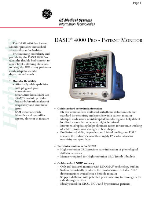
DASH 4000 P RO - P ATIENT 监测器说明书
DASH® 4000 P RO - P ATIENT M ONITORHighlights•Gold-standard arrhythmia detection–EK-Pro simultaneous multilead arrhythmia detection sets thestandard for sensitivity and specificity in a patient monitor–Multiple leads assure uninterrupted monitoring and help detectlocalized events that otherwise might be missed–Incremental updating helps eliminate noise, for accurate trackingof subtle, progressive changes in beat shapes-Predictive reliability dependent on 12-lead quality; our 12SL®remains the industry‘s most thoroughly 12-lead analysis forsensitivity and specificity•Early intervention in the NICU–High-resolution CRG provides early indication of physiologicalshifts in neonates–Memory required for High-resolution CRG Trends is built-in•Gold standard NIBP accuracy–Only full-featured monitor with DINAMAP® technology built-in–System consistently produces the most accurate, reliable NIBPdeterminations available in a bedside monitor–Stepped deflation with patented peak matching technology helpsride through artifact–Ideally suited for NICU, PICU and hypertensive patientsThe DASH 4000 Pro Patient Monitor provides unmatched adaptability at the bedside.By combining modularity and portability, the DASH 4000 Pro takes the flexible bed concept to a new level... allowing clinicians to bring the ICU to any patient or easily adapt to specific departmental needs.•Modular flexibility–Affordably add capabilitieswith plug-and-playconvenience–Smart Anesthesia Multi-Gas(SAM®) module providesbreath-by-breath analysis ofrespiratory and anestheticgases–SAM instantaneouslyidentifies and quantifiesagents, alone or in mixtureSize: 26 cm (diagonal); Type: Active-matrix color TFT; Resolution: 640 by 480 pixels; Number of traces: 6 (maximum); Number of seconds/trace: 4.9 at 25 mm/sec; Sweep speed: 6.25, 12.5, 25 mm/sec (with erase bar);Information window: Displays non-real-time information without obstructing the display of real-time information;Trim Knob®controlNotification: Audible and visual; Setting: Default and individual; Silencing: 1 minute, current alarm only;Pause: 5 minutes in Adult ICU mode, 3 minutes in Neonatal ICU mode, and 5 minute, 15 minute, or permanent pause in OR mode;Leads analyzed simultaneously: I, II, III, and V (multi-lead mode); Lead fail: Identifies failed lead;Voltage range: ± 0.5 mV to ± 5 mV; Signal width: 40 ms to 120 ms (Q to S); Heart rate range: 30 to 300 bpm;Input impedance: Common mode: > 10 Mat 50/60 Hz, Differential: > 2.5 Mfrom dc to 60 Hz;Monitoring: 0.05 to 40 Hz, Moderate: 0.05 to 25 Hz, Maximum: 5 to 25 Hz; Paper;Recorder: Diagnostic: 0.05 to 100 HzMonitoring: 0.05 to 40 Hz, Moderate: 0.05 to 25 Hz, Maximum: 0.05 to 25 Hz;Noise: < 30 µV (referred to input)Pacemaker detection/rejectionInput voltage range: ± 2 mV to ± 700 mV; Input pulse width: 0.1 ms to 2 ms; Rise time: 10 µs to 100 µs;Range Respiration rate: 0 – 200 breaths per minute; Base impedance: 100 – 1000 Ωat 52.6 kHz;Detection sensitivity: 0.4 to 10 Ωvariation; Waveform display bandwidth: 0.1 to 1.8 Hz (–3 dB);Input specificationsProbe type: YSI Series 400 or 700 (determined by input cable); Temperature range: 0°C to 45°C (32°F to 113°F); Resolution: ± 0.1°COutput specificationsParameters displayed: T1, T2; Accuracy: (independent of source) ± 0.1°C for YSI series 400 probes; ± 0.3°C for YSI series 700 probes;atrial, left atrial, intracranial, and special;Transducer requirements: Excitation voltage: 5 V dc ± 0.1%; Transducer output: 5 µV/V/mmHgInput specificationsRange: –25 mmHg to 300 mmHg; Offset: ± 150 mmHgOutput specificationsFrequency response: dc to 50 Hz (–0/+2 Hz); Zero balance range: ± 150 mmHg; Zero balance accuracy: ± 1 mmHg; Zero balance drift: ± 1 mmHg over 24 hours; Accuracy: ± 2% or ± 1 mmHg, whichever is greater (exclusive of transducer); Alarms: User-selectable upper and lower limits for systolic, diastolic, and mean pressurestime of last measurement; Measurement modes: Manual, auto, and stat in Adult ICU and OR modes; manual andauto in neonatal mode; Measurement range(s): Resolutions of 5 mmHg up to Maximum Adult/Pediatric/Neonate limits Systolic:Adult: 30-275mmHg; Pediatric: 30-235mmHg; Neonate: 30-135mmHg MAP:Adult: 20-260mmHg; Pediatric: 20-260mmHg; Neonate: 20-125mmHg Diastolic:Adult: 10-220mmHg; Pediatric: 10-220mmHg; Neonate: 10-110mmHg Pulse rate, as displayed in tabular trends:Adult: 30-200 bpm; Pediatric: 30-200 bpm; Neonate: 30-200 bpm Cuff pressure range:Adult: 0-275mmHg; Pediatric: 0-235mmHg; Neonate: 0-135mmHg; Overall system accuracy: Meets or exceeds SP 10-1992AAMI standards; Total cycle time: 20 to 40 seconds typical (dependent on heart rate and motion artifact);Automatic cycle times: 0 to 8 hours; T ubing length: 12 feet adult, 8 feet neonatal;Automatic cuff deflation: Cycle time exceeding 3 minutes (90 seconds neonatal), power off, or cuff pressure exceeds 294 mmHg (±6 mmHg) adult, 147 (±3 mmHg) neonatal Cuff sizes:Disposable: Large adult, adult, small adult, pediatric, small pediatric, and infant;Reusable: Thigh, large adult, adult, child, and infant;Input specificationsProbe type: In-Line or bath probe; Catheter size: 5F, 6F, 7F, 7.5F, and 8F; Injectate volume: 3, 5, or 10 cc Output specificationsParameters displayed: Cardiac output, blood temperature, injectate temperature, trial number;Range:Cardiac output: 0.2 – 15 (liters per minute); Blood temperature: 30 – 42°C; Injectate temperature: 0 – 30°C Accuracy:Cardiac output: ± 5%; Blood temperature: ± 0.2°C; Injectate temperature: ± 0.3°C;22PPR range: 30 – 300 beats per minute; Accuracy: Actual accuracy depends on probe. Please reference manufacturer’s specifications.;SpO 2 : ± 2% (70 – 100% SpO 2 ); ± 3% (50 – 69% SpO 2 ); PPR: ± 3 beats per minute;Information displayedInspired and expired CO 2 concentrations in %, mmHg, or kPa; respiratory rate, continuous CO 2 waveform Measurement rangePi CO 2 /Fi CO 2 : 0 to 100 mmHg / 0 to 13%; Pe CO 2 / Fe CO 2 : 0 to 100 mmHg / 0 to 13%; RR: 0 to 120 breaths/min AccuracyCO 2: 5% of reading or ±2 mmHg, whichever is greater; Display resolution: 1 mmHg; Rise time: Less than 60 msec;Respiration rate accuracy: ±1 breath/minType: Novametrix Medical Systems’ CAPNOSTAT III; Sensor: Mainstream non-dispersive infrared (NDIR) absorption,dual wavelength ratiometric, true single beam optics.Warm-up time: 2 minutes warm-up time to meet accuracy specifications; waveform immediate upon power up, calculated end tidal after two breaths; Cable Length: 10 feet (3.0 m)CalibrationSimple one-step calibration; no calibration gases required.Airway adaptersTypes: Adult reusable (standard), adult disposable, neonatal;Deadspace/chamber volume:Adult reusable: < 5 cc, Adult disposable: < 5 cc, Neonatal: < 0.5 cc AlarmsCO 2 : High inspired CO 2; high/low expired CO 2; Respiratory rate: Adjustable high and lowSpecifications2006309-001–2001.01–pdf–V1.0 Printed in Germany Printed on chlorine free paper.European Headquarters Marquette Hellige GmbH P .O. Box 60 02 6579032 Freiburg • Germany Tel. +49 761 45 43 - 0Fax +49 761 45 43 - 233World Headquarters GE Medical SystemsInformation Technologies, Inc.8200 West Tower Avenue Milwaukee, WI 53223 • USA Tel. +1 414 355 5000Fax +1 414 355 3790Asia PacificGE Marquette Medical Systems11th Floor, The Lee Gardens, 33 Hysan Ave.Causeway Road • Hong Kong Tel. +852 2100 6300Fax +852 2100 6292DASH ® 4000 P RO - P ATIENT MONITORVertical resolution: 200 dots/in; Number of waveform channels: four;Capacity: 3.9 Ah; Charge time: Less than 4 hours each; Run time: 4 to 5 hours; Battery life: 500 cycles to 50% capacityCooling: convection; Heat dissipation: 240 Btu/hr (max)Operating ConditionsAmbient temperature: 0-40°C (32-104°F) While charging batteries: 0-35°C (32-95°F);CO 2 Sensor: 10-40°C (59-104°F); Relative humidity: 5-95% @40°C;Vibration: MIL-STD 810E, Method 514.4, Category 1; Altitude: -610 to 4.570 m (-2,000 to 15,000 ft.)Storage Conditions (do not exceed):Maximum: 70°C (158°F) at 95% relative humidity; Minimum: –40°C (–40°F); CO 2 Sensor: –30 to 65°C (–22 to 149°F);This product or some features of this product may not be available in all countries. Call your local GE representative for more information.GE Medical Systems Information Technologies reserves the right to make changes in specifications and features shown herein, or discontinue the product described at any time without notice or obligation. Contact your GE Medical Systems Information Technologies Representative for the most current information.。
网络分析仪的操作与介绍
网络分析仪的操作与介绍首先,简单认识一下各种不同用途及类型品牌的网络分析仪一﹕仪表使用注意事项1 °防静电:仪表应良好接地.如果不接地网络分析仪会有105V或75V漏电压,对人体和仪器都会有伤害.2 °清洁:仪表要注意清洁和保养.否则仪表使用时间会减短.3 °防潮:在仪表的旁边不要放水、饮料、酒精等各种对仪表有损害的液体.4 °仪表的输入和输出功率不要过高.5 °仪表的电源开关不要频繁关断和打开.特别不要刚刚打开就立即关掉,仪表关掉后要至少5~10分钟打开.6 °强磁性的物体禁止放在仪表旁边、和磁铁、隔离器等物品.7 °带有磁性的起子,扳手禁止直接接触仪表显示屏或按键.8°各种仪器和射频连接器连接时,要注意拧的方法.只允许用于在自然状态下拧紧.二﹕操作说明方法1. AGICENT公司E5062A系列网络分析仪设置标准方法.2. 开机预热3-5分钟.3. 基本设置A. 按Center硬键设置中心频率.B .按 Spa硬键设置工作带宽.C .按Marker硬键1.....4软键.设置频点.D .按Display硬键→按Allocate、Channels软键可把仪表分成不同的频段进行测试.如果选择X1,则仪表一个频段.按Num of、Traces 软键.选择1、2、3、4.则可把这个频段分成2.3.或4长轨迹,即是2、3、4、个信道;按Allocate、Channels软键,可把屏幕分成几个所需要的窗口,一般设置两个窗口,按Channel、Pre硬键,是将完全独立的频段进行切换;按Trace、Prev是将不同的信道进行切换;按Channel、Max硬键,是将所选中的频段进行放大;按Trace、Max硬键,是将所选中的信道进行放大.4.1.按Sweep、Setup硬键→Points软键选择401扫描点;按Power软键选择+10dBM输出功率(这是调SP.BP.MS等各种无源器件设置的)当测试有源器件时,仪表输出功率一定只能设置为-20dBM,以免烧坏仪表.4.2 按AVG硬键→IF、Bandwidth软键选择30KHZ.4.3 按Cal硬键→Calkit、85032B/E软键→85032B/E(这要看校准件是什么样的CALKIT,如有的是85032F)三﹕标准方法双端口标准>a. 按Cal硬键→Calibrate软键→按2-Portcal软键→按Reflection 软键,.在仪表Port1端口电缆上接“开路”标准件→按Port1 Open、Open CFS软键→换下“开路”标准件,接上“短路”标准件→按Port1 Short、Short C软键→按F“短路”标准件,接上“负载”标准件→按Port Load、Broad band软键→换下“负载”标准件→在仪表Port2 端口电缆上接“开路(Open)”标准件→按Port2 Open、Open(F)软件→换下“开路”标准件,接上“短路(Short)”标准件→按Port2 Short、Short(F)软键→换F“短路”标准件,接上“负载(Load)”标准件→按Port 2Load、Broad band软键→按Return软件返回→换下“负载”标准件→将Port1电缆, Port2电缆用“双阴”短接→按Transmission软键→按Port1-2Thru软键→按Return软键返回→按Done软键完成. 标准完后,仪表显示屏下角会出现“Cor”字符,表示标准正确.b.这时,可在Port1端口接上“负载”标准件检验标准效果,在Port2端口接上“负载”标准件检验标准效果;若回波总在70dB 以或驻波比在1.00处,则表示已标准好.c.标准的存储:标准完后,按Savel、Recall硬键,选择Save、State 软键,可直接在State 01*~08*存储,或选择File dialog…存储在仪表的D盘上.标准文件的调用:按Savel Recall硬键→Recall State软键,可直接在State 01*~08*调用或直接选择Filedialog……..从D盘上调用.四﹕仪表常用设置a. 设置存储文件或(建立图像存储文件夹)按Savel Recall硬键→Explorer软键→出现一个文件夹,这时可在文件夹上打到My Computer的文件夹,右键单击鼠标,出现一个菜单栏,然后选择Map Network、Drive……弹出一个对话框,有两栏 Drive: Folder: 在Drive中选择文件所在的盘符,一般为G; 在Folder中点击会出现一个下拉菜单,选择/DZ3/D/N6(其中N6指明相对应的仪表编号)然后,按Finish.这时会弹出一个对话框,要求输入用户名现密码,可在用户名中输入: Administrator 密码无,按OK完成.b. 存储整个屏幕按System硬键→Screen Image…软键.出现一个文件夹选择Input from the front panel→输入文件名→Enter→Save.即可.c. 存储通带/驻波现取消:选择某一个信值.如S21信值,按Display 硬键→Date软键→men软键→Date math、OFF软键→Date/men软键. 取消存储时,按“OFF”软键.d. 划分辅助界线:选择某一信道如信道S21,按Analysis 硬键→limit Test、OFF软键→按Editlimitline软键(改成limit line 、ON 形成) →按 Editlimitline软键→会出现一个窗口,按Type →OFF关闭. Max最大. min 最小. →选择Max 或min→在 BeginStimucus对应的本质内输入开始频点(横向的终点);在BeginResponse 对应的框内输入起始值,如-63dB(纵向的起点).在End Response对应的框内输入终止值(纵向的终点)如 -73 dB,按 Focus 硬键→Return软键,即可.e. 扫描频点的设置:选择某一频点(如频点S),按Marker Search硬键→按Max / min 软键(最大值/最小值.一般是按Max软键) → Tracking 、OFF软键,即可. 如何确搜索范围:如上后,按Searchrange、OFF软键→ Start软键(输入搜索起始频点) → Stop 软键(输入搜索终止频点)f. 参考值的设置按 Scace 硬键,出现一系列软键,其中常用的有下面几个软键:f.1 Scace /dic 代表每一格的高度.如回波形式,一般设为10dB /Divf.2 Referenceposition 代表从起始值到最下面的总格数3°Reference Volue代表起始值. 如在回波形式一般设为OdB 驻波形式一般为1.具体操作如下:1°回波形式,选中某一信道,如S21 按Scace 硬键 1. Scace/ Div软键→输入10 dB /Div 2. Referenceposition软键→输入10 Divf.3. Reference Volue软键→输入0 dB 2°驻波形式:同上只不过一般分别输入. 180m/div; 0div 1g. 格式的设置:选择某一信道,如S21.S11.S12,按Format 硬键→Cogmag软键(回波形式)或→SWR软键(驻波形式)一般情况:S11.S22设为驻波形式. S21.S12设为回波形式h. 打印. 按System 硬键→Print软键,开始打印,全屏显示主工作区,按 Entry off 硬键.附:调试区存图到电脑上的设置(小型局域网):按Savel Recall硬键→Explorer软键→出现一个文件夹,这时可在文件夹上打到My Computer的文件夹,右键单击鼠标,出现一个菜单栏,然后选择Map Network、Drive……弹出一个对话框,有两栏Drive: Folder: 在Drive中选择文件所在的盘符,一般为G;在Folder中点击“浏览”,选择服务器所在的电脑名称,然后,点需要的盘符.这时会弹出一个对话框,要求输入用户名现密码,可在用户名中输入: Administrator 密码无,按OK完成.问题解答:找不到服务器所在的电脑名称?答:要排除的几类 1,网线没插好,2,仪表的IP设置:设置方法:A按Savel Recall硬键→Explorer软键→出现一个文件夹,这时可在文件夹上找到网上邻居的文件夹,右键单击鼠标,出现一个菜单栏,点属性,B,在对话框里,右键点“本地连接”,点属性,在出现的对话框里,选择“Internet协议(TCP/IP),点属性,然后输入相应的IP,点确定五﹕仪表单词英译汉Aug平均Allocate 分配,分派Analysis分析Administrator超级管理员Bandwidth 带宽Browse 浏览band 带状物Broad 宽阔的、广大的Cal 标准Center中心Channel水道.航道.频道Done 完成Drive 驱动Dialog 对话,对白Display 显示,展览explorer 探测员Edit 编辑Enter 进入,开始从事file 文件format格式,版式.形式Finish 完成Folder 文件夹From 从……起Front 前面Focus 焦点image. 映像.图像Input 输入kit 装备load 载装,负载limit 界限.范围my computer我的电脑max 最大min 最小Map networkdrive 映像网络驱动Marker 标记.频点next 下一个.下一次off 关on 开Open 开放.找开.开路Panel 控制板.面板Point点position位置Power 电力,功率Port 港口,端口R:return 回来,返回 Recall召回,调用Reference 参考 response响应Range 区域 reflection反射,思考S:save 存储 system 系统,体系Scale 标度,标尺 Screen屏幕Span 跨距,带宽 search搜索Sweep 打扫,扫描 short 短的,短路State 状态.说明 stimulus 刺激T:trace 痕迹.踪迹transmission 播送,发射Test 测试,试验Trigger扳机,触发器。
Varian 4000GCMS中文操作手册-6.02
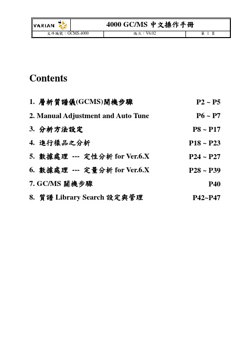
1.10.2 出現調整圖譜後,打開 MS 前門,使用一字起子調整正面中間下方 RF 調整旋 鈕,將電腦畫面下方之圖形調整至對角直線,並將計量表調整至最小(無固定 值,盡量調小即可)。完成後按下 Done。
將此計量表調至最小
將此線調整至左下至 右上對角直線
4000 GC/MS 中文操作手冊
文件編號:GCMS-4000 版次:V6.02 第 5 頁
4000 GC/MS 中文操作手冊
文件編號:GCMS-4000 版次:V6.02 第 2 頁
1. 層析質譜儀(GCMS)開機步驟
1.1 打開 He 氣鋼瓶總源頭(注意:當鋼瓶總壓低於 200 psi 時需更換鋼瓶,輸出壓則固定在 80 psi,同時需檢視氣體鋼瓶過濾桶是否飽和)。 1.2 打開電腦,並點選工具列(tool bar)上的系統控制鍵(System Control)。
4000 GC/MS 中文操作手冊
文件編號:GCMS-4000 版次:V6.02 第 10 頁
Autosampler:此為軟體自動偵測出之模組,無須更改。 Syringe size (μL):10μL 如使用不同 Size 之注射針,請於此處設定。有三種 Size 可供選擇 5、10 及 100μL。 Injection Mode:注射模式之選擇,自動注射器具備有七種注射模式,可依 User 之需求自行設定。若具備有分流/不分流之注射器時,建議選擇 Std Split/Splitless 模式。 Sample Depth(%) :定義為注射針深入樣品瓶之深度。0%代表注射針深入至樣 品瓶瓶蓋 Septum 下方,而 100%則代表注射針深入至樣品瓶底部。通常建議設定 為 90%。 Solvent Depth(%) :定義為注射針深入洗針瓶之深度。0%代表注射針深入至洗 針瓶瓶蓋 Septum 下方,而 100%則代表注射針深入至洗針瓶底部。通常建議設定 為 90%。 Default clean:此部分無須更改。 Clean Mode: (i) Pre-inj Solvent Flushes:定義為注射前使用洗瓶洗針之次數。 (ii) Pre-inj Sample Flushes:定義為注射前使用樣品洗針之次數。 (iii) Post-inj Solvent Flushes:定義為注射後使用洗瓶洗針之次數。 (iv) Clean Solvent Source:自動注射器(8400/8410)具有三個洗針瓶,可依 User 所 需調整洗針次序 。 例如於設定 I&II 時則代表洗針時會先以一號洗瓶清洗後再以二 號洗瓶清洗。
网络分析仪操作规范
ADD
MAX
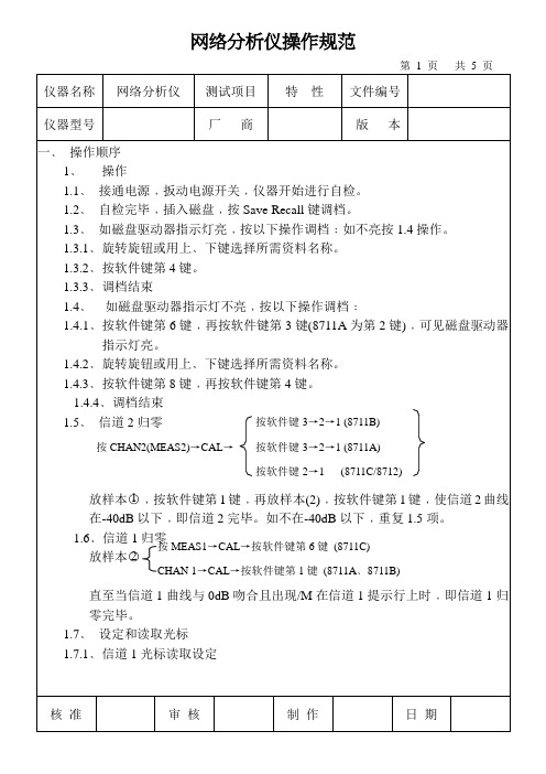
LIMIT菜单﹐再重新选择所需的相应模式。
LINE
比如增加最大线﹐选择(软件键)按BEGIN FREQUENCY从数字
键盘中输入所需开始频率﹐然后再按相应单位软件键﹐同时End Frequeney软
体键输入结束频率﹐按Beging LIMIT软件键输入开始限制。按END LIMIT软
仪器型号
厂商
版本
根据需要选择不同的刻度以便观察测试图象。
MFAS1信道﹐按MEAS1→按SCALE键→按Reference Position软件键输入所需
数字﹐再按软件键第一键加以确认。
信道与信道1相似。
4.1.2选择MEAS2(2信道)
(1)按MEAS2
(2)按软件键对应对的对REFLECTION(反馈)键。
3.4﹑资料存入磁盘结束。
4﹑如磁盘驱动器指示灯不亮﹐按以下操作存盘。
4.1﹑按软件键第6键选择磁盘类型。
4.2﹑按软件键第3键选择Internal3.5#Disk。见磁盘驱动器指示灯亮后﹐按软件键第8键﹐回到SAVE RECALL菜单。
4.3﹑按软件键第1键﹐资料会以STATEn.STA存入磁盘。
(软件键)→按Prior menu(软件键)→将一张好的磁盘写保护开关打开并插入到磁盘驱动器中→按Start(软件键)→此时屏幕上会显示资料以Plotn.pcx存盘﹐当磁盘驱动器指示灯灭后即资料以Plotn.pcx文件存盘。
2﹑第二次存盘﹕
按HARDCOPY键→将一张好的磁盘写保护开关打开并插入到磁盘驱动器中→按Start(软件键)→此时屏幕上会显示资料以Plotn.pcx存盘﹐当磁盘驱动器指示灯灭后即资料以Plotn.pcx文件存盘。
网络测试仪使用教程

பைடு நூலகம்
网络测试仪使用方法-设备连接异常处理思路
1、海思授权失败
PAD 设备管理界面-系统-海思授权正常应显示已授权,若显示未授权则设备 的 COM 口是连接不上的,海思提供周期性授权更新,主机上网即可授权, 采用手机 USB 共享网络授权:连接一部手机-设置-移动网络-个人热点-更多网络共享-USB共享网络-打开开关-PAD上重启主机,重启完成连接后授权即可 获取,下面是依次操作流程截图;
➢ 多终端:标配6部终端,最大可支持8部终端同时测 试,同时支持NSA/SA网络测试;
➢ 多业务:支持5G数据业务FTP-DL/UL、Ping等业 务,同时支持VoNR语音/视频、EPSFB、Volte等语 音(MOS)测试;
➢ 长续航:内置4块高容量蓄电池,可连续保持6-8个 小时的测试,电池支持热插拔,可无间隙更换;
网络测试仪使用方法-设备连接异常处理思路
3、手机无参数上报
启动测试后告警提示手机无参数上报,主要检查以下项: ➢ 确认手机卡放置卡槽 1(见右图) ➢ 手机端口设置处于 Balong 模式 ➢ 手机仅充电下 ADB 调试是否打开 ➢ 手机软件重新启动下 ➢ 手机是否开机插卡---重启手机 ➢ 尝试插拔一下手机的 USB 线 ➢ 是否恢复关闭软件,删除 knowyou/cte/config/下所有文件,重
网络测试仪使用方法-设备连接异常处理思路
2、COM端口未连接
PAD 设备管理界面-手机状态显示 APP 已连接/COM 口未开启, 代表手机硬件连接正常但软件上的端口连接异常,用以下方式进行排 查: ➢ 查看海思授权是否已经授权---未授权请做授权失败操作 ➢ 检查手机开口设置---balong模式、USB 调试和仅充电下 ADB ➢ 手机 IMEI 获取是否正常---异常按照手机 APP 连接方式进行排查 ➢ 手机 SIM 卡是否放置 1 槽位,手机默认获取 1 槽位信息(见右图) ➢ 测试手机不能连接 WIFI---关闭 WIFI ➢ 手机卡是否开机插卡---重启手机
SiteAnalyrer中文使用手册

SITE ANALYZER™电缆和天线无线系统测试仪操作说明适用机型SA-1700EX, SA-1700EXP SA-2500EX, SA-6000EX开机对于第一次通电、发生故障后,需要重置仪器(返回到默认值,第119页)。
自检仪器在加电时执行自动自检。
如果自检失败,请参阅第126页的故障排除中可能的原因和纠正措施。
如果问题仍然存在,则返回服务站。
仪器的按键网络分析仪有两种类型的键。
第一种类型称为硬键,总对应于一个特定的功能。
键的功能不改变而且被印在仪器表面或键上。
第二类型被称为软键(功能键)。
在显示器的左侧五个按键就是软键。
每个软键具有的功能可以根据操作模式而变化。
键的功能将被在显示器的左边或下一次按键而确定。
1.功能键:激活键的右侧所描述的功能。
2.硬键Mode :启动模式菜单。
用于选择测量匹配、故障定位、测量功率或实用模式。
Config :激活当前模式下的配置菜单。
使用此设置可改变参数(如频段、距离和单位)。
Calibrate :激活校准菜单。
Marker :激活标记菜单。
用于标记的开启或关闭以及移动激活了的标记。
3.数字键输入所选择项目中的数值数据或如定义所描述的功能。
4.Esc键在菜单中:返回到上一级菜单。
在数据输入时:退出数据输入而不改变其值。
5.Enter键在列表选择时:选择列表中突出显示的项目。
在数据输入时:退出数据输入,更改该值。
6.光标键左箭头在数据输入时:每按一次删除先前输入的一个字符数据。
在标记使用中:每按一次向左移动激活的标记一个点。
其他情况:所定义的功能描述。
右箭头在标记使用中:每按一次向右移动激活的标记一个点。
其他情况:所定义的功能描述。
上箭头在数据输入时:增加数值。
在标记使用中:将标记移动到扫描线的最大值。
按对比度键后:增加显示屏的对比度。
其他情况:所定义的功能描述。
下箭头在数据输入时:减少数值。
在标记使用中:将标记移动到扫描线的最小值。
按对比度键后:减少显示屏的对比度。
网络分析仪的使用方法介绍
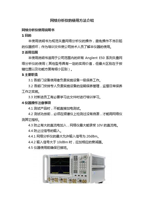
网络分析仪的使用方法介绍网络分析仪使用说明书1 目的本使用说明书为规范矢量网络分析仪的操作,避免操作不当引起的仪器损坏;作为培训文件使公司技术人员了解本仪器的使用。
2 适用范围本使用说明书适用于公司范围内的所有Anglent E50系列矢量网络分析仪的使用(其他型号具有一定的实用价值,但最大区别在于按键位置以及功能方面有细小区别)。
3 主要职责3.1 各部门设备使用者负责实施设备一级保养工作。
3.2 各部门安排专人负责实施设备的定期保养管理,监督日常保养工作之实施。
3.3 对新进员工有必要学习此文件时进行培训学习。
4 仪器操作注意事项4.1 测试产品时,不能直接加电测试。
4.2 测试功放前,必须在频谱仪上检测过没有自激,才能用网络仪测其它指标。
4.3 防止有大的直流电加入,网络仪最大能承受10V的直流电。
4.4 防止过信号的输入。
4.4.1 网络分析仪的最大允许输入信号为20dBm。
4.4.2 输入信号大于10dBm时,应加相应的衰减器。
4.5 仪器使用前确保已接地。
网络分析仪概述网络分析仪是一种功能强大的测试测量的仪器仪表,只要按照流量正确使用和操作,可以达到极高的精度,它通过使用自身的信号源来进行比对和测量其他电子设备、电子元器件、电子零件、网络接头、电缆线等电气特性和性能参数是否符合标准和要求,能精确地测量入射波、反射波、传输波中的幅度和相位信息,通过比值测量法定量描述被测器件的反射和传输特性。
它的应用十分广泛,在很多行业都不可或缺,尤其在测量无线射频(RF)元件和设备的线性特性方面非常有用。
本文主要是针对网络分析仪自身的特点,介绍网络分析仪在使用过程中需要注意的使用步骤、使用要求、基本的校准方式以及如何使用它去执行测试任务等。
网络分析仪在正确使用的前提下,是某些最精确的射频仪器,典型的精度为± 0.1 dB和±0.1度。
它可以进行精确,可重复的RF测量,提供的配置和测量能力像他们应用范围一样广泛。
网络分析仪使用说明书
1 目的本使用说明书为规范矢量网络分析仪的操作,避免操作不当引起的仪器损坏;作为培训文件使公司技术人员了解本仪器的使用。
2 适用范围本使用说明书适用于公司范围内的所有Anglent E50系列矢量网络分析仪的使用(其他型号具有一定的实用价值,但最大区别在于按键位置以及功能方面有细小区别)。
3 主要职责3.1 各部门设备使用者负责实施设备一级保养工作。
3.2 各部门安排专人负责实施设备的定期保养管理,监督日常保养工作之实施。
3.3 对新进员工有必要学习此文件时进行培训学习。
4 仪器操作注意事项4.1 测试产品时,不能直接加电测试。
4.2 测试功放前,必须在频谱仪上检测过没有自激,才能用网络仪测其它指标。
4.3 防止有大的直流电加入,网络仪最大能承受10V 的直流电。
4.4 防止过信号的输入。
4.4.1 网络分析仪的最大允许输入信号为20dBm 。
4.4.2 输入信号大于10dBm 时,应加相应的衰减器。
4.5 仪器使用前确保已接地。
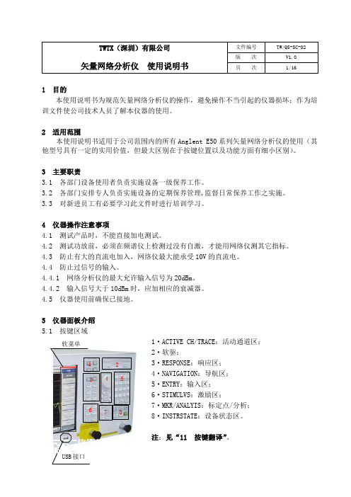
5 仪器面板介绍 5.1 按键区域1·ACTIVE CH/TRACE :活动通道区; 2·软驱; 3·RESPONSE :响应区; 4·NAVIGATION :导航区;5·ENTRY :输入区; 6·STIMULVS :激励区;7·MKR/ANALYIS :标定点/分析;8·INSTRSTATE :设备状态区。
注:见“11 按键翻译”。
1 2 36 4 57 8软菜单USB 接口矢量网络分析仪使用说明书版次V1.0 页次2/165.21 2 3 4 5Tr1 S11 SWR 1.000/Ref 1.0000Tr2 S21 Logmag 10dB/Ref 0.00dBTr3 S22 SWR 1.000/Ref 1.00001.表示通道编号;2.表示通道类型;3.表示通道的格式;4.表示通道在显示屏上每格所表示的数值;5.表示通道在显示屏上参考线所在的格子数值。
SIR-4000中文说明书
SIR-4000中文说明书第一章简介1.1打开系统包装箱感谢您购买GSSI SIR@4000先生(以下简称SIR4000)。
货运箱中的装箱单包含您的订购的所有设备。
你应该根据装箱单检查你收到你的设备。
如果你发现一个项目或者是失踪了或者损坏,请立即通过电话或传真联系你的销售代表。
SIR4000系统包含:1、数字控制单元SIR4000主机1台2、运输箱1个3、电池2块4、充电器1个5、遮阳板1个6、操作指导书1本7、操作指导书CD1张8、GSSI优盘1个天线、电缆和数据后处理软件需要另外购买。
1.2简述SIR4000是一个轻便、便携式、地面透视雷达系统。
该系统兼容GSSI单一数字天线,单一的模拟天线,或双频率天线,有着广泛的应用领域。
系统将不支持操作数字和模拟天线同时使用。
SIR 4000的各种组件描述如下。
控制单元的主要特征是键盘,控制旋钮,和10.4英寸LED显示屏1024×768像素的分辨率,连接器面板(HDMI视频,USB 2.0,以太网,串行端口I / O,数字和模拟天线连接器、电力、GPIO连接器,usb),电池插槽,和指示灯。
,您可以查看实时数据或在回放模式。
尽管有遮阳板,但它在明亮的阳光下频幕也是清晰可见。
但是,长时间暴露于阳光直射会导致屏幕过热并可能影响屏幕可见性。
有两个自锁板的单元包含电池槽,usb端口和以太网端口。
打开面板,旋转锁销,直到它松了。
关闭面板按坚定,把锁销,旋转销,直到它收紧。
请参阅下面的图进行进一步的细节。
控制单元左侧是电池槽,可安置10.8 V可充电锂离子电池。
经过调查一个完全充电电池壳工作大约两个半小时(2.5h)。
2块电池是可通过电池充电器充电或通过控制单元和标准交流源AC适配器连接给单块电池充电。
电池充电的时间大约一个半到两个小时(1.5 - 2)。
在使用过程中一定要保持左侧和右侧面板覆盖单元关闭,以确保任何灰尘或污垢进入单位的内部。
兼容性SIR 4000不能与以下GSSI设备兼容:1、结构检测中:不能支持平板和电子阅读器2、不支持Y增益3、软件:SIR 4000的数据只能被radan7数据打开和处理,不支持radan5和6版本。
驻波表操作手册

SA-2500A&SA-4000操作指南一、正确连接仪器的电源,检查无误,打开电源开关,如屏幕右侧黄灯闪烁,说明仪器处于随机充电状态。
二、仪器进入正常工作状态后,我们就要对仪器进行设置、校准,做好测试前的准备工作。
三、四、我们按一下侧菜单显示如下:在这种状态下,我们按在按890-960MHz。
五、频段设置好以后,我们就可以对该仪器进行校准了。
接上2米长测试电缆,因为我们测试时要连着电缆一起进行,所以校准时,要把电缆可能引入的误差一起消除掉。
电缆的一端接SA-2000A的输出端口,另一端先接上校准件的OPEN端按Calibrate键,仪表左侧菜单显示如下:这时按以下屏幕会有一条迹线在扫,结束后有提示音,取下开路器换接上Short端口,按一下Load端口,按1,且有提示音,然后按一下屏幕上原来的Calibration off会变为Calibration Full。
说明校准已经完成,可以进行测试了。
六、测试时,首先测试某一基站的天馈线的驻波比通过N(M)-7/16(F)转接适配器把仪器与被测天馈线联接起来,这时仪表的屏幕就会出现被测天馈线的驻波比曲线。
按通过RS232口联接PC机或联接HP打印机。
七、故障定位测试,如果该基站天馈线的驻波比超差,这时就要进行故障定位测试,判断问题发生在哪一个位置。
八、进行故障定位测试,首先要对被测距离进行设定,按按在这种状态下,按按的长度来定,尽量接近,不要设定太长,如被测天馈线的长度大约为50米,我们可设定为55米或60米,这样可以使测量的结果更加准确。
九、被测距离设定好以后,我们还要对被测天馈线的类型进行选定,因为针对不同的馈线,电磁波在其内部传播的速度不一样,给故障定位造成误差,所以我们要正确选择被测馈线的类型,具体操作:在屏幕上会出现仪器内部预置的70种电缆类型及介电常数等,根据被测电缆的类型,我们对应选定。
如遇特殊情况,仪器内部预置的70种电缆类型不包括被测电缆类型,用户可在仪器上自己设定被测电缆的类型及其介电常数,也可达到同样的目的。
思博伦STC培训讲义-testcenter

‹#›
PROPRIETARY AND CONFIDENTIAL
HOME
WebClient Example
Download Client
Download Firmware
Download Docs
Access Online Training
‹#›
PROPRIETARY AND CONFIDENTIAL
•
• •
下一代网络测试面临的挑战
•
• • • • • • •
高密度和高扩展性测试 完整的网络测试方案(L2-L7,核心功能, 汇聚功能,接入功能) 复杂的测试和高效方便的测试配置 实验室测试环境的真实性 模拟集成的环境(许多故障只有在集成环境 下才能出现) 丰富而有效的故障诊断工具 自动化解决方案 多用户测试
HOME
思博伦通信主要测试仪表举例
SmartBits Spirent TestCenter Avalanche AX4000 Abacus
数据网络测试平台 超高端口密度数据测试平台 网络应用层仿真/性能/网络安全测试仪 宽带网络测试平台 大话务量呼叫测试系统
DLS
‹#›
PROPRIETARY AND CONFIDENTIAL
HOME
DeviceBlock的生成
向导生成
手工添加
向导生成
‹#›
PROPRIETARY AND CONFIDENTIAL
HOME
Device Block 配置举例
Device count Device Block mode
Steps
‹#›
PROPRIETARY AND CONFIDENTIAL
RSS 4000用户指南
i
目录
查看直播信息 ································································ 3-6 观看直播 ······································································ 3-7
Polycom® RSS™ 4000 系统 用户指南
6.0.0 | Apr. 2010 | 3725-32870-001
商标信息 Polycom®、 Polycom “ 三角形 ” 徽标、 以及相关联的 Polycom 产品名称和符号是 Polycom, Inc. 的注册商标和 / 或服务符号,是在美国和其他国家 / 地区注册的和 / 或习惯法上的符号。 其他所有商标均为其各自所有者的资产。 专利信息 随附产品受美国和其它国家 / 地区的一项或多项专利和 / 或 Polycom, Inc. 正在申请的专利所保护。
普通用户配置 ················································································ 3-1
个人设置 ·········································································· 3-1 虚拟录制会议室(VRR) ···················································· 3-2 呼入 VRR 开始一个录制 ·················································· 3-2 修改 VRR ····································································· 3-2 录制节目 ·········································································· 3-4 查看节目文件 ································································ 3-4 回放与下载节目文件······················································· 3-4 修改节目文件 ································································ 3-5 直播 ················································································ 3-6 开始一个直播 ································································ 3-6
Arista LANZ 实时网络性能和抗压监控说明书

Arista LANZ OverviewOverviewArista Networks’ Latency Analyzer (LANZ) represents the nextstep in the revolution in delivering real-time networkperformance and congestion monitoring. For the first time,administrators and applications can now achieve real-timevisibility into network traffic patterns and their effect oncongestion, application latency and performance.Rather than wait for the effects of network congestion to trickleup to the application layer, LANZ can pro-actively detectimpending congestion events allowing preemptive capacityplanning before the effect is seen at the application layer. Thenetwork administrator’s dreaded support call of “the network isslow”, can now be answered by the forensic analytic dataprovide by Arista’s LANZ.The benefits Arista’s LANZ functionality will provide tonetwork administrators:•Real time visibility of congestion hotspots at themicrobursts level•Pre-empt network conditions before they induce latencyor packet loss•Isolate potential bottleneck early, enabling pro-activecapacity planning•Historically trending of network congestion events andtheir correlation to specific application traffic patterns.Highlights:•LANZ provides unparalleled visibility into congestion hotspots •LANZ time stamping provides for precision historical trending for congestion events Technical BulletinThe Drive for LANZNetwork engineers design High Performance Computing (HPC), Data Center (DC) and High Frequency Trading (HFT) environments, with deterministic characteristics with regard to throughput, performance and latency. These characteristics will only be theoretical if the network infrastructure can’t provide real time monitoring of changing traffic patterns and their affect on the design characteristics.Traditional tools used to monitor network traffic patterns, such as RMON and SNMP, have been based on a polling model were data is typically collected at one second or longer intervals. What about the events that will occur within these polling intervals? With the evolution to 10Gbe attachment in the Data Center, within even a one second interval a 10Gbe interface could go from idle to forwarding over 28 million packets and back again. In a polling model this 28 million packet burst can become invisible. Decreasing the polling interval can be seen as a potential solution, however while also increasing the processing overhead the underlying hardware will typical only retrieve data at one second intervals, so the actual data collected would provide no extra visibility.Figure 1: Polling model, fails to provide the correct level of granularityThe significance and relevance of the final data collected can also be questioned, understanding the number of in/out octets of an interface and therefore it’s utilization, only provides basic information on the activity of the interface. It fails to provide the necessary information with regards to the affects this activity had on the network. Did the activity result incongestion and consequential an increase in latency? Was the activity the result of a temporary period of oversubscription and consequently packets being dropped? To truly understand the traffic patterns of today’s Data Center and their affect on network congestion and the consequential effect this may have on application throughput and latency a far more granular and pro-active model is required.Arista LANZArista’s Latency Analyzer (LANZ) is a pro-active event driven solution, purposely designed to provide real-time visibility of congestion hot spots and their effect on application performance and latency at a nanosecond resolution. The level of granularity LANZ delivers is made possible by it’s unique event driven architecture, rather than the traditional polling model that only provides visibility at discrete interval. LANZ reports on congestion events as they occur.The first and earliest indicator of a network congestion event, is the depth or occupancy level of a switch’s queue. During periods of congestion, where the offered load is beyond the available capacity of an egress port, a switch will attempt to manage the congestion by temporary buffering/queuing the frames that cannot be transmitted immediately. While buffering can prevent packet drops being observed by an application, the frames enqueued will introduce additional latency while extensive congestion will result in buffer exhaustion and eventual packet drops.Figure 2: LANZ+ Event driven Congestion detectionThe Arista LANZ functionality operates by monitoring and exporting in real time the queue length data on the switch based on a user configurable high and low threshold. At the point a queue threshold is crossed, indicating a period of congestion, LANZ+ generates a time stamped congestion event. This unique event driven model, allows congestion periods as short Switch'CPU'Queue ThresholdCongestion DetectedOver queue threshold eventas a few 100ns to be detected and reported. Detecting congestion events at the queue level rather than the egress ports as a whole, LANZ+ provides visibility of congestion not simply at the network level but at a more granular traffic class or application level.While providing granular visibility of application congestion events at the nanosecond level, LANZ delivers time stamped analytic data on the affects the event had on network latency and application throughput for accurate correlation with external monitoring tools.LANZ GranularityThe key parameter that defines the precision at which congestion events can be observed and their affect on network latency is the granularity at which queue occupancy is measured. The level of granularity is determined by the segment size used to define the occupancy level of a queue. Packets in a queue are stored across one or multiple segments, the exact number being dependent on the size of the packets and the segment size itself A large segment size in KiloBytes (e.g. 384KB) could mean the same level of congestion being detected regardless of whether one or a 1000 packets are stored in the segment. With a smaller byte sized segment a far greater level of granularity can be achieved, as this will allow detection of congestion when only one or two packets are queued.Figure 3: The smaller Segment size provides more granular view of the queue occupancy level To provide fine grain visibility into congestion periods as short as a few 100ns, LANZ detects queue congestions events in small byte size segments (480 bytes) with the ability to detect when just two segment are enqueued in a buffer. This provides the ability to detect congestion when just a single packet is queued in the buffer.Effects on LatencyAs queued packet must wait for the buffer to clear before they can be transmitted, any buffering will introduce an extra level of latency into the application. The accuracy, with which this latency can be calculated, is also defined by the segment size used to determine queue occupancy.The effect on application latency is determined by both the number of frames buffered and their individual size. For example a single 480 byte frame, due to serialisation delay will result in 400ns of additional latency on a 10Gbe interface or 4us on a 1Gbe interface. The latency increasing as more packets are buffered and with larger packet sizes.480 byte segment + 20 byte overhead = 500 bytesPacket Overhead = Preamble (7 bytes)+ Start frame Delimiter (1 byte) and Inter-Frame Gap (12bytes)10Gbe interface will transmits 1 byte of data in 0.8nsThus 500bytes will be take 0.8ns * 500 = 400ns to be transmittedAs queue occupancy is detected by the number of segments held in the buffer rather than the number of packets, which could be of variable size, a smaller segment size will provide a more accurate estimate of the actual data bits stored in the queue and therefore it’s latency. With a larger segment size (e.g. KB) a single 64 byte packet could occupy a whole KB segment, resulting in a latency estimate in microsecond rather than the actual nanoseconds value.LANZ Time stampingLANZ provides real-time visibility into network congestion events as short as a few 100 nanoseconds. To provide an audit trail each event generated and stored by LANZ is time-stamped with 10us resolution. This allows accurate historical trending of network congestion events and precise correlation to specific application traffic patterns at the microsecond level. LANZ ImplementationMonitoring of congestion operates by allowing user configurable high and low thresholds to be set on each of the switch’s queues. Providing threshold setting at the queue rather than the port level allows the monitoring of specific applications and traffic classes within the network. The high threshold defines the occupancy level before LANZ monitoring should start on the specific queue. The low threshold defining the level at which the occupancy of the queue needs to drop, before monitoring stops on the queue.When a queue high threshold is first crossed a congestion “Start” record is generated, recording the time of the events occurrence, the queue length and the packet drop count at the start of the event. While the queue remains over the high threshold, periodic “Update” records for the queue are created, reporting, the new queue length and any effect the congestion has on the packet drop count. At the point the queue falls below the defined low threshold a congestion “End” record is created. The congestion “End” record providing a summary of thecongestion event; calculating highest queue length over the congestion period, when it occurred and the duration of the overall congestion eventFigure 4: LANZ report for a congestion event detected on Interface 46 traffic class 1 The effect each congestion records has on latency is automatically calculated from the number of segments enqueued during each event and is viewable from the CLI.Figure 5: LANZ output calculating the network latency effects for each congestion eventdetected on Interface 46 traffic class 1LANZ Data CollectionLANZ provides congestion data events in real-time, making it possible to monitor and alerton congestion at microsecond resolution rather than seconds. This level of resolution enables accurate historical trend analysis of congestion events. Operating in real-time makes pro-active capacity management a reality. Rather than wait for applications to report a drop in performance, capacity management tools can now have the relevant data present to them in real-time, enabling them to react pre-emptively on transient hotspots before congestion accumulates to affect the application layer.To make this possible and provide maximum versatility with regard to how the data maybe consumed, the LANZ data is presented in a number of open standard formats for bothreal-time and historical usage•CLI Output: All congestion data is available instantaneous and continuously via theCommand line Interface (CLI) of the switch for quick and easy analysis of congestiondata by network administrator•Syslog Messaging: For automatic alerts on the occurrence of a congestion event, LANZ will generate a Syslog message when queue threshold is exceeded.•CSV format: For storing LANZ data for historical trending and third party analysis, the congestion data saved in a CSV which can be stored on the flash, USB, SSD or anexternal file system (FTP, TFTP, NFS)•Congestion Data Stream*: To provide real-time visibility of congestion events for pro-active monitoring and potential capacity management, congestion events can be streamed in real-time to external third-party monitoring tools. The streamed data utilizes the industry standard format of Google Protocol Buffers (GPB).。
LHA2000 LHA4000 系列快速网络指南说明书

Before You Start:• Make sure you have a router and high-speed Internet access (not included).LHA2000 / LHA4000 SERIESCongratulations! You can now view video from your cameras on your PC or Mac.• Connect your DVR to your router using an Ethernet cable (see the Quick Connection Guide for details).• Upgrade your DVR firmware and client software or mobile app to the latest versions.PC / Mac SetupFind Your Device IDRecord your information below:DEVICE ID:2The Device ID is printed on a label on the top panel of the DVR.Device ID: xxxxxxxxxxx12• Please note that an upload speed of 2 Mbps is required for remote video streaming (3 Mbps and above recommended). Up to 3devices may connect to thesystem at the same time.a • PC Users: Download and install Lorex Client 13 for PC f rom . Download and install the client software:• Mac Users: Download and install Lorex Client 13 for Mac from . Double-click toextract the software, then drag the software to Applications .b c Click Login .d Double-click the Lorex Client 13 icon ()on the desktop or Applications list.Enter theDVR’s Device ID recorded in section 1Enter the following information:Enter the DVR’s Client Port (default: 9000)Enter the DVR’s user name(default: admin )Enter the secure password you created for the DVRe All connected cameras are shown onscreen in the Lorex Client 13 home screen.NOTE: For full instructions on how to use the Lorex Client 13 software for PC and Mac, see your DVR’s instruction manual at .Copyright © 2019 Lorex CorporationAs our products are subject to continuous improvement, Lorex reserves the right to modify product design, specifications and prices, without notice and without incurring any obligation. E&OE. All rights reserved.Quick ReferenceDefault access information:• Default user name: admin • Default password: 00000000Default system ports:• HTTP Port: 80• Client Port: 9000If you have forgotten your password, contact Lorex technical support.See the label on top of your DVR for your Device ID If you are having troubleconnecting, try the following:• Restart the DVR by disconnecting the power adapter, then reconnecting it.• Ensure the DVR is connected to the router using an Ethernet cable and then restart the DVR.• Double check the Username, Password, and Client Port.• Ensure your DVR has the latest firmware.• Ensure your mobile app is up-to-date.TroubleshootingNeed Help?Visit us online for up-to-date software and complete instruction manualsClick on the Downloads tab4Visit Search for the model numberof your product Click on your product in thesearch results 321a Tap Sign up and enter your emailaddress and password to create a new account.b c d Smartphone / Tablet SetupTap ADD DEVICE .Install the free LorexSecure app from the App Store or Google Play Store.Tap the Lorex Secureicon to open the app.Tap Security SystemTap ADD DEVICEef Scan the QR code on the top of your DVR using the camera on your smartphone or tablet.g Enter your DVR’s user name (default: admin )and the secure password you recorded on the Quick Connection Guide. Tap DONE to connect.h Congratulations! You can now view video from your cameras on your smartphone or tablet.3Tapto seevideo from allconnected cameras, or tap one of the channels to see video from a single camera.。
- 1、下载文档前请自行甄别文档内容的完整性,平台不提供额外的编辑、内容补充、找答案等附加服务。
- 2、"仅部分预览"的文档,不可在线预览部分如存在完整性等问题,可反馈申请退款(可完整预览的文档不适用该条件!)。
- 3、如文档侵犯您的权益,请联系客服反馈,我们会尽快为您处理(人工客服工作时间:9:00-18:30)。
AX4000网络监测测试的操作手册
1.安装AX 4000GUI软件到PC上。
安装UDP Server软件到远端服务器上。
运行远端UDP
Server软件。
2.启动AX4000机箱电源,连接AX4000控制卡的以太网接口和控制PC机的网口。
AX4000
的确省IP地址是192.168.0.66。
注意:新到的机箱可能没有IP地址,需要通过串口对控制板上的以太网口的IP地址进行设置,串口速率为115200,用户名为root,密码spirent或ax4000。
3.启动AX4000 GUI软件,从Program—Spirent communications—AX controller software
4.81—Network Access GUI。
在Global system assignment中输入AX4000的IP地址。
4.双击IP地址的机框图标,进行机框初始化过程。
此过程需要2分钟左右,时间长短取
决于板卡的数量。
5.初始化结束后,显示当前机框所拥有的板卡,双击你测试所需要的板卡,取得控制权。
6.点击AX/4000图标,进入到AX/4000 4.81的图形化界面中。
7.选择相应的测试板卡,如ip over Ethernet 10/100Mb板卡,双击板卡图标,进入板卡设
置界面,选择setup,设置板卡为自协商还是强制10M,100M,全双工,半双工等特性。
确省板卡为自协商。
测试时要选择强制100M,全双工。
注意:测试时,同AX 4000相连的交换机或路由器的端口属性要同AX 4000的端口属性设
为一致。
8.选择GEN图标,进入到IP发送流量设置界面中,选择ARP SETUP,选择arp request
和arp reply。
9.选择Traffic Source ,进行发送流量的编辑,选择测试模式为:IP editable test blocks,
选择Ethernet II数据包,按insert加入到sequence definition中。
10.双击相应的数据包,进入到Packet Definition窗口中,在ip head中,设定发送数据包的
源地址和目的地址。
然后选中ip头,按右键选择insert, insert UDP头,编辑UDP包的源端口号和目的端口号,编辑UDP的目的端口号为6201。
注意:此端口号为Echo Server 的端口号。
选择arp request选项,以确保目的MAC地址的解析。
11.按OK完成数据包的编辑。
12.在test datagram length中,选择fixed length,设定fixed datagram length为相应测试数据
包包长,注意:此包长为datagram的包长度,实际发送的数据包长为18byte+datagrame 包长,即要发送256字节的包长,在fixed datagram length中要设置238字节。
13.在distribution中,选择Periodic packets,设定相应的发送速率,如1200packets/s。
注意:此时max bandwidth和max load都会根据你设定的包速率自动计算,实际上仪表发出的流量大家要看max load的流量,max bandwidth是去除了包间隔和前导码后的流量。
14.其他保持确省,按ok完成发送流量的设置。
按load或save保存或载入数据流的设置。
15.此时,ARP request窗口会出现。
按start进行arp解析。
如果用到网关,请填入网关的
IP地址,此时会解析到网关的MAC地址。
16.按Ana图标,进入到IP Analyzer窗口。
在IP Analyzer中,选择左上方的Analyzer Setup,
在test block中,去除auto-detect选项,在starting by byte number: 中设置43。
按ok保存。
17.在IP Analyzer窗口中,选择MaxTag选项,察看接收的数据包,选择RUN,进行接收数
据包进行分析。
数据包会根据机框,端口和mAXTag的编号来定义数据流,双击相应的数据流察看详细信息,如丢包,时延等。
如果需要图表显示,则拖动数据流到右边的图表图标上,然后打开图表窗口,选择你要察看的数据项目,按start即可。
图表结果可通过Export to txt.file导出。
18.在IP Generator窗口中,选择RUN,进行流量发送,按statistic按钮,显示所有发送数
据包的情况。
19.如果要定时测试,就选择RUN—TIMED—SET,设定运行的时间。
20.如要结束测试,则选择Stop generate, stop analyzer, 并退出主程序。
注意,一定要AX4000
GUI软件界面上按quit退出以释放端口的控制权。
