安腾rx2620上11i.23系统镜像实验
HP-UX 11.11 11.23 11.31 镜像步骤

# /usr/sbin/lvlnboot -v -r /dev/vg00/lvol3
7、 检查BDRA的正确
# /usr/sbin/lvlnboot -R /dev/vg00
8、 检查镜象有没有正确创建
重镜像
lvextent -m 1 /dev/vg00/tellin /dev/dsk/c1t6d0 /dev/dsk/c5t0d7
删除死设备PV Biblioteka vgreduce -f vg00
mv /etc/lvmtab /etc/lvmtab.bak
rm /etc/lvmtab
vgscan
lvreduce -m 0 /dev/vg00/lvol1
Mkboot –a “hpux (52.3.0;0)/stand/vmunix” /dev/rdsk/c0t3d0
5. Mirror the root logical volume to the above disk
Lvextend –m 1 /dev/vg00/lvol1 /dev/dsk/c0t3d0
both synchronized and valid:
1. Run vgcfgbackup to save the volume group configuration information, if
necessary.
2. Remove the disk from the volume group using vgreduce
3. Physically disconnect the bad disk and connect the replacement
手动ghost11.0.2使用方法
很同情的告诉你,俺当年自己摸索GHOST时也碰到这种情况了。
所以,当你在不熟知道GHSOT的时候前几次让会的操作,自己学会。
说下你中招的原因:恢复时候有个FROM DISK和FROM PARTITION,DISK在这里的意思就是整个硬盘了,PARTITION默认情况下对应的才是C盘,你应该是选了FROM DISK,把备份文件恢复覆盖了全盘。
正确的操作是FROM PARTITION。
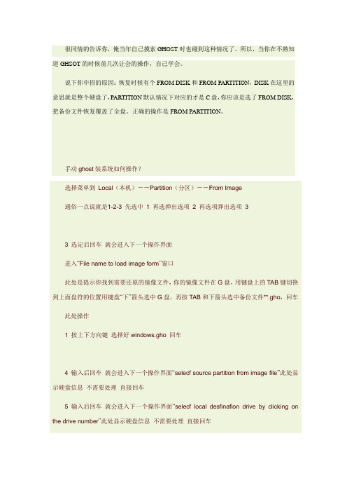
手动ghost装系统如何操作?选择菜单到Local(本机)--Partition(分区)--From Image通俗一点说就是1-2-3 先选中1 再选弹出选项2 再选项弹出选项33 选定后回车就会进入下一个操作界面进入“File name to load image form”窗口此处是提示你找到需要还原的镜像文件,你的镜像文件在G盘,用键盘上的TAB键切换到上面盘符的位置用键盘“下”箭头选中G盘,再按TAB和下箭头选中备份文件**.gho,回车此处操作1 按上下方向键选择好windows.gho 回车4 输入后回车就会进入下一个操作界面“selecf source partition from image file”此处显示硬盘信息不需要处理直接回车5 输入后回车就会进入下一个操作界面“selecf local desfinafion drive by clicking on the drive number”此处显示硬盘信息不需要处理直接回车如果您是双盘操作此处必定要选择好硬盘切记切记通常是选择第二块硬盘6 输入后回车就会进入下一个操作界面"Selecf destination partition from Basic drive:1"此处显示分区信息提示您是需要还原到哪珍上分区默认是还原第一个分区也就是C盘系统盘如果您是要还原到此分区不需要处理直接回车“1即C盘”7 输入后回车就会进入下一个操作界面此处显示信息此处是为了防止误操作再次提醒您是不是一定要还原镜像文件您到了这一步如果说没有十分的把握这是最后一次机会默认是NO 按下可以退出到起始界面如果选择YES 将进行还原操作此操作到了此处已经不可逆转此处需要的是用左右方向键选择YES 回车开始还原8 等到走到100%时,最后出现Clone Complete提示框,提示已经恢复完毕,给出二个选择,Continue和Reset Computer重启或稍后重启手动GhostGhost是款什么样的软件呢~他是一款数据备份和恢复软件,现在主要用于操作系统的备份与恢复,用正版windows xp系统安装光盘来安装系统的话,正常情况需要1个小时(含驱动程序安装)以上,而用Ghost来安装同样的windows xp只需五分钟以下就OK。
嵌入式实验流程
嵌入式实验流程一、接好实验箱。
两条通信线(网络线和串口线)和电源,不打开电源。
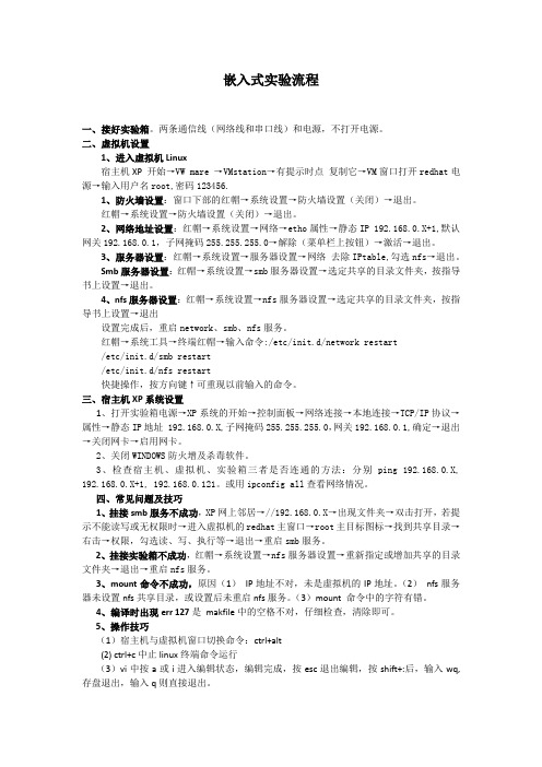
二、虚拟机设置1、进入虚拟机Linux宿主机XP 开始→VW mare →VMstation→有提示时点复制它→VM窗口打开redhat电源→输入用户名root,密码123456.1、防火墙设置:窗口下部的红帽→系统设置→防火墙设置(关闭)→退出。
红帽→系统设置→防火墙设置(关闭)→退出。
2、网络地址设置:红帽→系统设置→网络→etho属性→静态IP 192.168.0.X+1,默认网关192.168.0.1,子网掩码255.255.255.0→解除(菜单栏上按钮)→激活→退出。
3、服务器设置:红帽→系统设置→服务器设置→网络去除IPtable,勾选nfs→退出。
Smb服务器设置:红帽→系统设置→smb服务器设置→选定共享的目录文件夹,按指导书上设置→退出。
4、nfs服务器设置:红帽→系统设置→nfs服务器设置→选定共享的目录文件夹,按指导书上设置→退出设置完成后,重启network、smb、nfs服务。
红帽→系统工具→终端红帽→输入命令:/etc/init.d/network restart/etc/init.d/smb restart/etc/init.d/nfs restart快捷操作,按方向键↑可重现以前输入的命令。
三、宿主机XP系统设置1、打开实验箱电源→XP系统的开始→控制面板→网络连接→本地连接→TCP/IP协议→属性→静态IP地址 192.168.0.X,子网掩码255.255.255.0,网关192.168.0.1,确定→退出→关闭网卡→启用网卡。
2、关闭WINDOWS防火增及杀毒软件。
3、检查宿主机、虚拟机、实验箱三者是否连通的方法:分别ping 192.168.0.X, 192.168.0.X+1, 192.168.0.121。
或用ipconfig all查看网络情况。
四、常见问题及技巧1、挂接smb服务不成功,XP网上邻居→//192.168.0.X→出现文件夹→双击打开,若提示不能读写或无权限时→进入虚拟机的redhat主窗口→root主目标图标→找到共享目录→右击→权限,勾选读、写、执行等→退出→重启smb服务。
安装操作系统的实验报告

一、实验目的1. 掌握操作系统安装的基本方法。
2. 熟悉操作系统安装过程中的注意事项。
3. 提高动手操作能力,为以后使用操作系统打下基础。
二、实验环境1. 硬件环境:- CPU:Intel Core i5- 内存:8GB- 硬盘:500GB- 显卡:NVIDIA GeForce GTX 1050- 主板:华硕PRIME H310M-E2. 软件环境:- 操作系统:Windows 10- 安装工具:Windows 10安装镜像三、实验步骤1. 准备安装镜像- 将Windows 10安装镜像烧录到U盘或光盘上。
2. 设置BIOS启动顺序- 进入主板BIOS设置界面,将U盘或光盘设置为第一启动设备。
3. 启动计算机- 重启计算机,从U盘或光盘启动。
4. 开始安装操作系统- 进入Windows 10安装界面,点击“现在安装”按钮。
5. 选择安装类型- 选择“自定义:仅安装Windows(高级)”选项。
6. 选择安装磁盘- 在“驱动器选项”下,选择要安装Windows的磁盘分区,点击“新建”按钮创建新的分区,然后将所有磁盘空间分配给新分区。
7. 格式化磁盘- 在弹出的窗口中,选择“将磁盘格式化为NTFS文件系统”,点击“下一步”按钮。
8. 安装操作系统- 等待操作系统安装完成,期间会自动重启计算机。
9. 设置账户信息- 在安装完成后,根据提示设置用户名、密码等信息。
10. 安装驱动程序- 根据需要安装显卡、网卡等驱动程序。
11. 安装常用软件- 安装Office、QQ、浏览器等常用软件。
四、实验结果与分析1. 实验结果- 成功安装Windows 10操作系统,并完成了基本配置。
2. 实验分析- 本次实验中,按照步骤顺利完成操作系统安装,但在安装过程中遇到了以下问题:(1)在设置BIOS启动顺序时,需要根据主板型号进行设置,否则无法从U 盘或光盘启动。
(2)在格式化磁盘时,需要注意选择合适的文件系统,以免影响系统性能。
升腾重装系统

重装系统
第一步:
开机——按F12——U盘启动——开始程序——克隆工具——诺顿11.0或9.3 LOCAL——DISK——FROM IMAGINE——FNT文件——GHOST——690或945——OK——OK——YES
第二步:
系统自动克隆——选REPEAT COMPUTER——F12——SETUP——BOOT……——最后一个USB关闭(禁止用USB启动)——F10——回车(重启自动安装)——安装好后选择“用户”
用户管理设置:(默认密码:wml111111)
第一步:注销——administrator——密码:wml 111 111
第二步:XPE管理——wml 111 111——修改密码——地名+111111
第三步:升腾XXX向导——wml 111 111——设置密码——地名+111111
第四步:开始——控制面板——用户帐户——管理员密码——地名+111111
第五步:U盘——XPE系统——GHOST ——驱动安装
第六步:我的电脑——属性——计算机——更改——计算机名——(地名+IP后两位)
第七步:改IP
第八步:XPE管理——C:——提交设置——重启(修改各项后一定要提交设置,不然重启后系统自动恢复)
最好接入指纹仪重启,查看机子是否正常运行!
常见问题:
用DA690-2重软件的时候,有时会出现应用程序错误,这时应到XPE管理关闭保护后再装软件!!(可能是内存缓冲区不够用或者软件有病毒),
如果关闭保护还是装不了,那中能重装系统后,重新下一个安装软件再安装!。
HP Integrity rx2620-2 服务器
32 KB
32 KB
32 KB
256 KB
256 KB
256 KB
6 MB
3 MB
3 MB
1 GB/24 GB
PC2100 ECC 寄存式 DDR266A
内存和高速缓存上的检错和纠错(ECC)功能;备用内存芯片
提供 36 GB、73 GB 和 146 GB 硬盘
3 个热插拔 Ultra320 SCSI
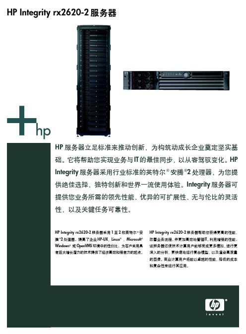
HP Integrity rx2620-2 服务器包含了您在运行 HP-UX、 Linux、OpenVMS 或 Windows 体系结构时所期望的全部 管理、可用性和安全特性。这些特性包括您用于监控、 部署及定制服务器和解决方案以获得高可用性所需的工 具——使您的计算资源得到合理利用。而且,当在 Integrity rx2620-2 服务器上运行 HP OpenVMS 时,您 可以将该系统与您现有的HP AlphaServer OpenVMS集 群相集成。
可用性 ● 投资保护
HP 服务器—立足标准,推动创新
HP Integrity rx2620-2 服务器助力企业,实现飞跃 HP Integrity服务器现在为您带来更强大的计算能力,创 造更多机会来利用英特尔® 安腾®2 处理器的优势,以应 对那些要求更高性能和可扩展性的工作负载。
当 Integrity rx2620-2 服务器用于 HP 业经证明的集群解 决方案时,通过采用英特尔 ® 安腾 ®2 处理器以及 HP 可 扩展处理器芯片组 zx1 获得的性能将进一步得到提升。 由于 HP Integrity rx2620-2 服务器仅有 3.5 英寸高 (2U),因此可将多台服务器组成集群,把空前的性能集 中到一个机架密集的低价位解决方案中。
安装系统实验报告
一、实验目的1. 熟悉操作系统安装的基本流程。
2. 掌握硬盘分区、格式化以及安装操作系统的基本方法。
3. 了解不同操作系统安装的特点及注意事项。
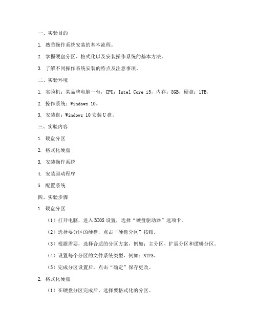
二、实验环境1. 实验机:某品牌电脑一台,CPU:Intel Core i5,内存:8GB,硬盘:1TB。
2. 操作系统:Windows 10。
3. 安装盘:Windows 10安装U盘。
三、实验内容1. 硬盘分区2. 格式化硬盘3. 安装操作系统4. 安装驱动程序5. 配置系统四、实验步骤1. 硬盘分区(1)打开电脑,进入BIOS设置,选择“硬盘驱动器”选项卡。
(2)选择要分区的硬盘,点击“硬盘分区”按钮。
(3)根据需要,选择合适的分区方案,例如:主分区、扩展分区和逻辑分区。
(4)设置每个分区的文件系统类型,例如:NTFS。
(5)完成分区设置后,点击“确定”保存更改。
2. 格式化硬盘(1)在硬盘分区完成后,选择要格式化的分区。
(2)点击“格式化”按钮,选择合适的文件系统类型和分配单元大小。
(3)点击“确定”开始格式化操作,等待完成。
3. 安装操作系统(1)将安装U盘插入电脑,重启电脑。
(2)进入BIOS设置,修改启动顺序,将U盘设置为第一启动设备。
(3)重启电脑,进入Windows 10安装界面。
(4)根据提示,选择安装语言、时间格式和键盘布局。
(5)点击“下一步”,选择安装类型,例如:自定义(高级)。
(6)选择要安装操作系统的分区,点击“下一步”。
(7)等待安装过程完成,重启电脑。
4. 安装驱动程序(1)进入系统后,打开“设备管理器”。
(2)查找需要安装驱动程序的设备,右键点击并选择“更新驱动程序”。
(3)选择“自动搜索更新的驱动程序软件”,等待驱动程序安装完成。
5. 配置系统(1)进入“控制面板”,点击“系统和安全”。
(2)在“系统”选项中,可以查看电脑信息、更改桌面背景等。
(3)在“安全”选项中,可以设置用户账户、家长控制等。
五、实验结果经过以上步骤,成功安装了Windows 10操作系统,并完成了驱动程序安装和系统配置。
网络Ghost克隆操作全程实例图解
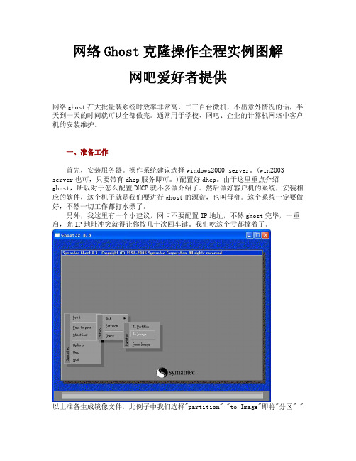
网络Ghost克隆操作全程实例图解网吧爱好者提供网络ghost在大批量装系统时效率非常高,二三百台微机,不出意外情况的话,半天到一天的时间就可以全部做完。
通常用于学校、网吧、企业的计算机网络中客户机的安装维护。
一、准备工作首先,安装服务器。
操作系统建议选择windows2000 server。
(win2003 server也可,只要带有dhcp服务即可。
)配置好dhcp。
由于这里重点介绍ghost,所以对于怎么配置DHCP就不多做介绍了。
然后做好客户机的系统,安装相应的软件,这个机子就是我们要进行ghost的源盘,也叫母盘。
这个系统一定要做好,不然一切工作都打水漂了。
另外,我这里有一个小建议,网卡不要配置IP地址,不然ghost完毕,一重启,光IP地址冲突就得让你按几十次回车键。
我们吃这个亏都撑着了。
以上准备生成镜像文件,此例子中我们选择"partition" "to Image"即将"分区" "生成为文件",需要整个"硬盘" "生成文件"以备克隆使用要选择"Disk" "to Image" 。
二、ghost网络版的安装小知识:通常讲的“ghost网络版”实际上只是抽取了ghost企业版的部分功能。
Ghost企业版的网络功能十分强大,它才是真正意义上的“ghost网络版”。
其标识为Symantec Ghost,与用于个人用户的Norton Ghost相区别。
对于ghost网络版安装,网上流传比较广的方式是通过修改配置文件,然后在客户端操作的时候,自己在命令行后面加个参数。
不过根据我们以往进行工作时的经验,这样做很浪费时间。
因为每一台客户机都要手动的执行一下命令,加上参数,而且每台客户端的参数都不一样,容易记混。
最好的情况是开机什么命令都不输入就可以直接开始ghost程序。
Transition Networks S323x Web GUI 登录指南说明书
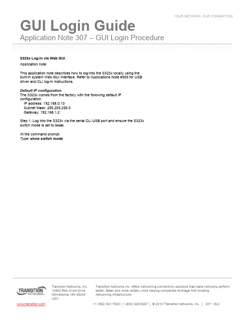
Application Note 307 –GUI Login ProcedureTransition Networks, Inc. 10900 Red Circle Drive Transition Networks Inc. offers networking connectivity solutions that make networks perform better, faster and more reliably while helping companies leverage their existingS323x Log-In via Web GUIApplication note:This application note describes how to log-into the S323x locally using the built-in system Web GUI Interface. Refer to Applications Note #305 for USB driver and CLI log-in instructions.Default IP configurationThe S323x comes from the factory with the following default IP configuration.IP address: 192.168.0.10Subnet Mask: 255.255.255.0Gateway: 192.168.1.2Step 1: Log into the S323x via the serial CLI USB port and ensure the S323x switch mode is set to local.At the command prompt:Type:show switch modeApplication Note 307 –GUI Login Procedure Transition Networks, Inc.10900 Red Circle DriveTransition Networks Inc. offers networking connectivity solutions that make networks perform better, faster and more reliably while helping companies leverage their existingTo change management mode:Type:set switch mode localReboot the S323x to make the change effective.Type: Reboot, then enterApplication Note 307 –GUI Login ProcedureTransition Networks, Inc.10900 Red Circle DriveTransition Networks Inc. offers networking connectivity solutions that make networks perform better, faster and more reliably while helping companies leverage their existingStep 2: Assign an IP address to the PC local Ethernet adapterUsing the same subnet address as the S323x (Example: 192.168.0.20)Step 3: Open a web browser and enter 192.168.0.10 in the URL address field,EnterApplication Note 307 –GUI Login Procedure Transition Networks, Inc.10900 Red Circle DriveTransition Networks Inc. offers networking connectivity solutions that make networks perform better, faster and more reliably while helping companies leverage their existingEnter password privateStep 4: Select ION Stack, then S323x to view main system menuApplication Note 307 –GUI Login ProcedureTransition Networks, Inc.10900 Red Circle DriveTransition Networks Inc. offers networking connectivity solutions that make networks perform better, faster and more reliably while helping companies leverage their existingTo logout of system, select System tab, then sign-out。
怎么用镜像文件重装系统?
使用镜像文件重新安装系统的步骤如下:
1. 获取镜像文件:首先,需要获取所需操作系统的镜像文件。
这通常是一个ISO文件,可以从官方网站或合法渠道下载。
2. 制作启动盘:将镜像文件写入可启动的存储介质中,如USB闪存驱动器或光盘。
你可以使用第三方软件,如Rufus、UNetbootin或Windows自带的工具(Windows 7及更高版本)来创建启动盘。
3. 设置计算机启动顺序:进入计算机的BIOS/UEFI设置界面,找到“启动顺序”或“引导顺序”选项,并将可启动的存储介质(制作的启动盘)置顶。
保存设置并重新启动计算机。
4. 启动安装:计算机重新启动后,它将从制作的启动盘启动,并进入安装界面。
根据提示选择语言、时区、键盘布局等设置,然后点击“下一步”。
5. 接受许可协议:阅读并接受操作系统的许可协议。
6. 分区和格式化:如果你想重新分区或格式化硬盘,可以在这一步骤中进行。
注意,这将删除硬盘上的所有数据,请提
前备份重要数据。
7. 安装操作系统:选择将操作系统安装到指定分区或完整硬盘上,并开始安装过程。
这可能需要一些时间,请耐心等待。
8. 完成安装:安装过程完成后,计算机将自动重新启动。
如果需要,根据提示进行一些初始化设置,如创建用户账号、设置密码等。
以上是使用镜像文件重新安装系统的一般步骤。
请注意,在操作过程中要小心,遵循操作系统安装程序的提示并根据实际情况进行调整。
另外,记得备份重要数据,以防数据丢失。
HPunix-11[1].23安腾安装
![HPunix-11[1].23安腾安装](https://img.taocdn.com/s3/m/fd4516e0f8c75fbfc77db26d.png)
通过串口安装hp操作系统一、环境1、硬件环境Hp-IA rx2600CPU 1.3MHZ 1个Memory 2000MB2、操作系统版本B.11.23串口连接COM1连接PC上COM1二、安装步骤1、设置终端连接使用COM1端口,与实际连接一致,点“还原为默认值(R)”按钮确定2、设置终端访真类型将终端访真设为:ANSI 其他不变,确定保存3、加电给rx2600加电4、放入第一张安装光盘5、中端会出现一个带选择框的界面选中第三项:Boot Configration回车然后选择:Boot From File回车然后选择驱动器名(光驱)回车然后选择IINSTALL文件回车然后等待系统自动开始运行安装程序这时等待时间比较长当出现以下界面时为选择终端类型选择2 回车继续在下面界面选择“Install HP-UX”,回车。
注:使用<tab>键移动光标,空格键或回车键选择确认键选择[OK] 回车出现HP-UX 安装向导界面以后步骤选默认即可,或按提示进行操作即可完成安装设置:安装完成进入系统后会出现设置向导,可以设置主机名,IP,DNS,NIS等,建议不要设置NIS,这个向导是要求都设置完才可以退出,如果没有NIS随便填一个的话,系统就会一直报错误信息。
如不使用设置向导可以使用命令进行IP等参数设置# set_parmsUsage: set_parms <argument>Where <argument> can be:hostnametimezonedate_timeroot_passwdip_addressaddl_netwrkor initial (for entire initial boot-time dialog sequence)例如设置IP# set_parms ip_address设置完IP就可以远程控制主机了,就可以不用串口了HP-UX还提供了一个系统管理工具sam# sam使用SAM可以进行大部分的系统管理工作。
Transition Networks NM2-xXx-2230-xx-201安装指南说明书
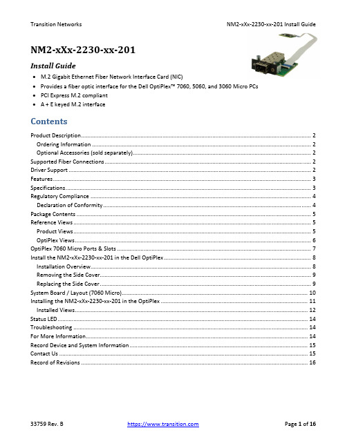
NM2‐xXx‐2230‐xx‐201Install Guide∙M.2 Gigabit Ethernet Fiber Network Interface Card (NIC)∙Provides a fiber optic interface for the Dell OptiPlex™ 7060, 5060, and 3060 Micro PCs∙PCI Express M.2 compliant∙A + E keyed M.2 interfaceContentsProduct Description (2)Ordering Information (2)Optional Accessories (sold separately) (2)Supported Fiber Connections (2)Driver Support (2)Features (3)Specifications (3)Regulatory Compliance (4)Declaration of Conformity (4)Package Contents (5)Reference Views (5)Product Views (5)OptiPlex Views (6)OptiPlex 7060 Micro Ports & Slots (7)Install the NM2‐xXx‐2230‐xx‐201 in the Dell OptiPlex (8)Installation Overview (8)Removing the Side Cover (9)Replacing the Side Cover (9)System Board / Layout (7060 Micro) (10)Installing the NM2‐xXx‐2230‐xx‐201 in the OptiPlex (11)Installed Views (12)Status LED (14)Troubleshooting (14)For More Information (14)Record Device and System Information (15)Contact Us (15)Record of Revisions (16)Product DescriptionTransition Networks NM2‐xXx‐2230‐xx‐201 M.2 Gigabit Ethernet or Fast Ethernet Fiber Network Interface Cards (NICs) provide a fiber optic interface for the Dell OptiPlex™ 7060, 5060, and 3060 Micro PCs. The NM2‐xXx‐2230‐xx‐201 consists of an M.2 NIC that installs into the OptiPlex PC’s M.2 “E key” interface, a fiber optic adapter that installs into the OptiPlex Micro PC’s Option port, and a 20‐pin Flat Flex Cable (FFC) that connects the NIC to the fiber adapter. The NICs are electro‐mechanically designed to be compatible (fit, form, function) with the Dell OptiPlex 7060 Thin Client PC through the use of its M.2 (E Key) slot.M.2 is known as the “next generation form factor” and is a specification for internally mounted computer expansion cards and associated connectors. Desktop PCs are being replaced by smaller computing devices (such as Thin Clients, Micro PCs, Ultrabooks, and Tablets) which typically have internal M.2 interfaces but do not have PCI or PCIe slots. Many users still need fiber Ethernet access, and without the external PCIe slot, there is no standard fiber interface on these devices.See the Dell OptiPlex manual for important notes, cautions, and warnings. Read the section “Before working inside your computer” before proceeding.Ordering InformationSKU DescriptionNM2‐GXE‐2230‐LC‐201 M.2 Gigabit Ethernet Fiber NIC (1000BASE‐SX, 850nm, MM, LC) (fixed optic). 1000Base‐SX 850nm multimode (LC) [62.5/125 μm fiber: 220 m/722 ft.] [50/125 μm fiber: 550 m/1804 ft.] Link Budget: 8.0 dBNM2‐GXE‐2230‐SFP‐201 M.2 Gigabit Ethernet Fiber NIC (1000Base‐X Open SFP Slot)NM2‐FXS‐2230‐SFP‐201 M.2 Fast Ethernet Fiber NIC. M.2 NIC, 100Base‐FX. M.2 NIC; 100Base‐FX to SGMII SFP media converter (included)Optional Accessories (sold separately)SFP Modules: Transition Networks offers a full line of small form factor pluggable (SFP) transceivers. See Transition Networks Optical Devices webpage for relevant SFP modules. See the related SFP manual for cautions and warnings.Supported Fiber Connections∙1000BASE‐SX, 850nm, MM, LC (fixed optic)∙1000BASE‐X, SFP Slot∙100BASE‐SGMII, SFP SlotDriver SupportWindows 10, 8.1, 8, and 7 (32 and 64 bit); LinuxFeatures∙IEEE 802.3‐2012 compliant∙PCI Express M.2 compliant (3.3V) ∙Full Duplex∙IPv6 Capable ∙A + E keyed M.2 interface∙Supports UEFI∙Jumbo frame support 9014 bytes ∙PXE Boot supportSpecifications•Standards: IEEE 802.3‐2012•Bus Slot: M.2 ‐ ‘2230‐D4‐A‐E’•Data Rate: 1000 Mbps (full duplex only)•Max Frame Size: 9014 bytes•Status LEDs: LINK/ACT ON = Link, Flashing = Activity•Dimensions (M.2 NIC) 2230‐D4‐A‐Eo Width: 0.87” [22 mm]o Depth: 1.18” [30 mm]o Height: 0.12” [3.08 mm]•Dimensions (Fiber Interface) Width: 1.65” [42 mm]o Depth: 2.05” [52 mm]o Height: 0.51” [13 mm]•Dimensions (FFC Cable) Length: 2.99” [76 mm]•Power Consumption (LC): 250mA @ 3.3V (0.8 Watts typical)•Power Consumption (SFP): 120mA @ 3.3V (0.4 Watts typical without SFP module) •Power Source M.2 interface connector: 3.3V (Refer to table 41 of M.2 Specification) •Environment:o Operating Temp: 0°C to +45°Co Storage Temp: ‐40°C to 85°Co Humidity: 5% to 95% (non‐condensing)o Altitude: 0 – 10,000 ft.•Weight: 0.1 lbs. [0.05 kg]•Warranty: LifetimeRegulatory ComplianceNote: Modification of NIC voids regulatory agency compliance.Compliance: CE Mark; Emissions: EN55032, FCC Part 15 Class A; Immunity: EN55024Emissions: EN 55032: 2012/AC: 2013; AS/NZS CISPR 32: 2013; VCCI V‐3/2015.04; ICES‐003, Issue 6: 2016; FCC Part 15 Subpart B.Immunity: EN 55024: 2010 (EN 61000‐4‐2: 2009; EN 61000‐4‐3: 2006 + A1: 2008 + A2: 2010; EN 61000‐4‐4: 2004 + AC: 2006 + A1: 2010; EN 61000‐4‐5: 2006; EN 61000‐4‐6: 2009; EN 61000‐4‐8: 2010; EN 61000‐4‐11: 2004).Declaration of ConformityHigh Risk Activities Disclaime r: Components, units, or third‐party products used in the product described herein are NOT fault‐tolerant and are NOT designed, manufactured, or intended for use as on‐line control equipment in the following hazardous environments requiring fail‐safe controls: the operation of Nuclear Facilities, Aircraft Navigation or Aircraft Communication Systems, Air Traffic Control, Life Support, or Weapons Systems ("High Risk Activities"). Transition Networks and its supplier(s) specifically disclaim any expressed or implied warranty of fitness for such High Risk Activities.Package ContentsVerify that you have received the following items. Contact your sales representative if any item is missing. Please save the packaging for possible future use.One TN‐SFP‐GE‐100FX SFP in anti‐static pouch (included with NM2‐FXS‐2230‐SFP‐01 version only).One M.2 NIC PCB attached to FFC Cable in anti‐static pouch.Parts in a 4x6 baggie (1 each): #4 Flat Head Screw, #4 Nylon Washer, #6 Black SEMS Screw.One NM2‐xXx‐2230‐xx‐01 Install Guide (this document).One Product Support Postcard.Reference ViewsProduct ViewsOptiPlex ViewsOptiPlex 7060 Micro Ports & SlotsDell OptiPlex 7060 Micro Front View: 1. Power button and power light. 2. Hard drive activity light.3. Headset/Universal audio jack port.4. Line‐out port.5. USB 3.1 Gen 2 Type‐C port with PowerShare.6. USB 3.1 Gen 1 port with PowerShare.Dell OptiPlex 7060 Micro Back View: 1. External antenna connectors (2) (optional). 2. DisplayPort/VGA/HDMI 2.0b/DP/USB Type‐C alt mode (optional). 3. USB 3.1 Gen 1ports (3). 4. Cable holder. 5. Padlock ring. 6. Network port. 7. USB 3.1 Gen 1 port (supports Smart Power On). 8. Service tag. 9. Kensington security cable slot. 10. DisplayPorts (2). 11. Power connector port.Dell Support for OptiPlex 7060: Diagnostics, Support topics & articles, Drivers & downloads, Manuals & documents, System configuration, and Parts & accessories.Install the NM2‐xXx‐2230‐xx‐201 in the Dell OptiPlexThe NM2‐xXx‐2230‐xx‐201 is designed to install in the Dell OptiPlex™ 7060, 5060, and 3060 Micro PCs.Caution: Only qualified persons should install the NIC. Failure to observe this caution could result in poor performance or damage to the equipment. Before installing the NIC, review the Pre‐Installation Checklist and Safety Precautions below.Caution: Wear a grounding device and observe electrostatic discharge precautions when installing the NIC in a system. Failure to observe this caution could result in damage to the NIC. Before installing the NIC, review the Pre‐Installation Checklist and Safety Precautions below. Before installing the NIC, ensure that system power is OFF, the power cord is unplugged from the power outlet, and that proper electrical grounding procedure has been followed.Warning: High voltage inside the system may present a safety hazard. Make sure that the system power is off before removing the cover. Unplug and disconnect the PC and then wait for 15‐20 seconds before plugging the NIC into the PC. When removing the NIC, unplug the Ethernet cable before removing the PC cover.Note: Refer to the Notes, Cautions, and Warnings in the Dell OptiPlex 7060 Service Manual. See Manuals & documents for details.Class I Laser Compliance: This product has been tested and found to comply with the limits for FDA Class I laser for IEC60825, EN60825, and 21CFR1040 specifications. Warning: Visible and invisible laser radiation when open. DO NOT stare into laser beam or view directly with optical instruments. Failure to observe this warning could result in damage to your eyes or blindness.Installation OverviewBefore installing your NIC, review the preceding sections, and then do the following:1.Verify that your system is using the latest BIOS.2.If you download the driver software, record the path where you saved the downloads.3.If your system is active, shut it down. Do not install the NIC until system power is completely removed.When system shutdown is complete, power OFF and unplug your system.4.Holding the NIC by the edges, remove it from its shipping package and place it on an antistatic surface.5.Check the NIC for signs of damage, particularly on the PCB edge connector. Caution: Never attempt to installa damaged NIC card. If the NIC is damaged, report it to Transition Networks.6.Remove the OptiPlex Side Cover. See Removing the Side Cover below.7.Gently remove the OptiPlex HDD.8.Remove the OptiPlex 15‐Pin DSUB Knockout.9.Insert the M.2 NIC into the OptiPlex Micro PC’s M.2 “E key” interface.10.Insert the fiber optic adapter into the OptiPlex Micro PC’s Option port.11.Replace the OptiPlex HDD.12.Replace the OptiPlex Side Cover.Removing the Side Cover1. Follow the procedure in “Before working inside your computer”.2. To remove the cover:a) Slide the release latch on the back side of the system until it gives a click sound to unlock the side cover [1].b) Slide and lift the side cover from the system [2].Replacing the Side Cover1. Place the cover on the system and slide the cover until it clicks into place [1].2. The release latch automatically locks the side cover to the system [2].System Board / Layout (7060 Micro)Installing the NM2‐xXx‐2230‐xx‐201 in the OptiPlexThe NM2‐xXx‐2230‐xx‐201 consists of a M.2 NIC that installs into the OptiPlex Micro PC’s M.2 “E key” interface, and a fiber optic adapter that installs into the OptiPlex Micro PC’s Option port.1.Remove PC cover.2.Gently remove the HDD Assembly. See the Dell documentation.3.Remove the 15‐Pin DSUB knockout.4.Insert the M.2 NIC into the OptiPlex Micro PC’s M.2 “E key” interface.5.Secure the M.2 NIC Assembly into place using the Securing Screw.6.Insert the fiber optic adapter into the OptiPlex Micro PC’s Option port.7.Attach to PC Case using Black SEMS Screw #6‐32x1/4”, and partially tighten to hold in place as shown below.8.Align #4 Standoff with Top Hole in PC Case.9.Slip #4 Nylon Washer on top of #4 Standoff and insert #4 Screw to secure.10.Tighten using Black SEMS Screw #6‐32x1/4”.11.Lift Locking Lever of FFC Connector on fiber optic adapter.12.Insert end of 20‐Position FFC Cable into fiber optic adapter, with Pins facing down.13.Push Locking Lever Down to Lock. Check that Cable is secure. See figure below for final placement.14.Gently replace the HDD Assembly.15.Replace PC cover.16.Install the SFP in the open SFP slot. On the fixed optic version, connect the fiber adapter/connector.17.Power up the PC.Installed ViewsPXE Boot Loader from PXE boot loader image pre‐loaded: https:///download/19186/Intel‐Ethernet‐Connections‐Boot‐Utility‐Preboot‐Images‐and‐EFI‐Drivers.Intel i210 PROSet Drivers from If your PC does not automatically detect the NM2‐xXx‐2230‐xx‐201 NIC, download and install the standard i210 PROSet drivers from Intel at /content/www/us/en/support/network‐and‐i‐o/ethernet‐products/000005686.html.The Intel® PROSet for Windows* Device Manager is an extension for Windows Device Manager. When you install the Intel PROSet software, tabs are automatically added to the supported Intel adapters in Windows Device Manager.These features allow you to test and configure wired Intel® Ethernet Adapters.The links below apply to the NM2‐GXE‐2230‐xx‐201, the NM2‐FXS‐2230‐SFP‐201, and –D versions. At each link, there is a 32‐bit and a 64‐bit download for each OS.Intel® Network Adapter Driver for Windows* 7.Intel® Network Adapter Driver for Windows* 8.1.Intel® Network Adapter Driver for Windows® 10.The full set of Intel Network Adapter Drivers for download (e.g., for Linux, Windows Server, etc.) is available. Transition Networks Resources page has Drivers (ZIP format) for Windows 10 32bit and 64bit Drivers, Windows 7 32bit and 64bit Drivers, and Windows 8 32bit and 64bit Drivers.Status LEDThe Media Converter has a status LED for checking Link/Activity:Link/ACTivity LED On = Link; Flashing = Activity. Color is amber when 100M.TroubleshootingThis section lists some common problems, their causes, and potential recovery steps.1. Confirm the Pre‐Installation Checklist items on page 8.2. Verify the Hardware Installation Procedure on page 9.3. Check that the cabling is securely attached. See the FOA troubleshooting guide or the SFP manual.4. Check for a mismatch of speed, duplex, protocol, or cable type.5. Make sure the SFP is plugged in to the open SFP slot before you power on the PC. Failure to do so will cause the device to fail, in which case you must shut down and restart the PC.6. Use the troubleshooting procedures in the Dell™ OptiPlex™ User’s Guide.7. Use the troubleshooting procedures on the PXE Boot Loader webpag e as required.8. Use the troubleshooting procedures on the Intel i210 PROSet Drivers webpage as required.9. Verify that the link partner is active and can send/receive traffic; make sure partner settings match; verify that the port is enabled; try connecting to another port or link partner. Check for incompatible or conflicting devices / settings.10. Run Windows Device Manager and scan for changes.11. Check if the PC’s BIOS version is appropriate and update to the latest. See the PC documentation.12. Run the PC diagnostics (e.g., Dell Quick Test or Dell pre‐boot diagnostics).13. Automatically detect and update drivers and software if you are connected to the Internet from the computer that needs updated drivers from /support/network/sb/CS‐031482.htm.14. Record information and contact TN Technical Support. See Recording Model and System Information below.For More InformationTo view the Dell™ OptiPlex™ User’s Guide at the Support Center web page:1.Click Start → Help and Support → Dell User and System Guides → System Guides.2.Click the User’s Guide for your computer.The User’s Guide is also available on the optional Drivers and Utilities media.Technical information in this document is subject to change without notice.See our SFP Products for more SFP information.The Fiber Optic Association, Inc. provides a Technical Bulletin on “Guidelines For Testing And Troubleshooting Fiber Optic Installations” at /tech/guides/TT3.pdf Other FOA Technical Bulletins to be used as references for the design and planning of the network can be downloaded from the FOA Tech Topics website.Record Device and System InformationAfter performing the troubleshooting steps, and before calling or emailing Technical Support, please record as much information as possible in order to help the TN Tech Support Specialist. Record the following information: 1. Product ID: ___________________________ MAC Address: ________________________________________ Serial #: _______________________________ Board Rev: ___________________________________________ LED status: __________________________________________________________________________________ 2. Record the System information: Check your computer documentation for support information.PC make and model: ________________________________________________________________________ Operating System: __________________________________________________________________________ BIOS version: ______________________________________________________________________________ Intel i210 Driver version: _____________________________________________________________________ PC’s Icon Tray indication: _____________________________________________________________________ Connected Device(s): ________________________________________________________________________3. Provide your TN service contract number: _______________________________________________________4. Describe the failure: _________________________________________________________________________ ___________________________________________________________________________________________ ___________________________________________________________________________________________5. Describe any action(s) already taken to resolve the problem: ________________________________________ ___________________________________________________________________________________________ ___________________________________________________________________________________________Contact UsTechnical Support: Technical support is available 24‐hours a dayUS and Canada: 1‐800‐260‐1312International: 00‐1‐952‐941‐7600Main Officetel: +1.952.941.7600 | toll free: 1.800.526.9267 | fax: 952.941.2322******************** | ************************** | ******************************AddressTransition Networks10900 Red Circle DriveMinnetonka, MN 55343, U.S.A.Web: https://Record of RevisionsRev Date NotesA 7/24/18 Initial release for production.B 11/14/18 Incorporate technical and editorial changes.Trademark notice: All trademarks and registered trademarks are the property of their respective owners. Copyright restrictions: © 2018 Transition Networks. All rights reserved. No part of this work may be reproduced or used in any form or by any means ‐ graphic, electronic or mechanical ‐ without written permission from Transition Networks.。
ReadyNAS OS 6.2 Desktop 2 系统安装指南说明书

Guida all'installazione dei sistemi di storage ReadyNAS OS 6.2 DesktopSommarioContenuto della confezione. . . . . . . . . . . . . . . . . . . . . . . . . . . . . . . 3 Installazione di base . . . . . . . . . . . . . . . . . . . . . . . . . . . . . . . . . . . . 4 Riformattazione dei dischi . . . . . . . . . . . . . . . . . . . . . . . . . . . . . . . . 7 Informazioni aggiuntive . . . . . . . . . . . . . . . . . . . . . . . . . . . . . . . . . . 9Contenuto della confezioneSistema ReadyNASCavo Ethernet Alimentatore e cavo di alimentazione(variano a seconda del modello) IMPORTANTE:leggere tutti gli avvisi di sicurezza riportati nel manuale hardware del sistema prima di collegarlo a una fonte di alimentazione.Installazione di baseAl termine della procedura descritta di seguito, il sistema ReadyNAS è pronto per l'utilizzo in un ambiente di produzione. La configurazione richiede circa 15 minuti.Per configurare il sistema di storage:1.Installare tutti i dischi disponibili che si desidera utilizzare nelsistema ReadyNAS.Nota: se si utilizzano dischi precedentemente formattaticontenenti dati, è necessario riformattarli prima di continuare.Consultare Riformattazione dei dischi a pagina 7.Per un elenco dei dischi supportati, consultare l'Elenco deglihardware compatibili all'indirizzo/readynas-hcl.Per informazioni sull'installazione dei dischi, consultare ilmanuale hardware relativo al sistema.2.Collocare il sistema in un luogo ben ventilato.I dischi ad alta capacità possono surriscaldarsi in modoconsiderevole. È importante accertarsi che le uscite della ventola non siano ostruite.Per un elenco completo delle posizioni da considerare,consultare il manuale hardware del sistema.3.Collegare l'alimentatore al cavo di alimentazione.4.Collegare l'alimentatore al retro del sistema e il cavo dialimentazione a una presa elettrica o a una basetta di alimentazione.5.Utilizzare un cavo Ethernet per collegare la porta Ethernet delsistema di storage alla rete.6.Se necessario, premere il pulsante di alimentazione peraccendere il sistema.7.Attendere che il LED di alimentazione diventi blu senzaintermittenza o che la schermata di visualizzazione dello stato indichi l'indirizzo IP del sistema.8.Accedere al sito Web con uncomputer connesso alla stessa rete LAN (Local Area Network) e tramite la stessa connessione a Internet del sistema ReadyNAS.Nota: se il computer non dispone di un accesso Internet,installare ed eseguire l'utility RAIDar. Scaricare RAIDar su uncomputer connesso a Internet e trasferire il file scaricato su un computer sulla stessa LAN del sistema ReadyNAS. La versione più recente di RAIDar è disponibile all'indirizzo:/raidar.9.Fare clic su pulsante Discover (Rileva).ReadyCLOUD rileva automaticamente il sistema ReadyNASsulla rete.Il sistema ReadyNAS è contrassegnato dall'etichetta NEW(NUOVO).10.Fare clic sul pulsante Setup (Installazione).11.Selezionare la modalità da utilizzare per l'installazione delsistema.•Opzione 1. Selezionare Join Now(Accedi ora).a Accedere a ReadyCLOUD oppure creare un nuovoaccount utente.b Seguire le istruzioni visualizzate per configurare ilsistema ReadyNAS.•Opzione 2. Selezionare Join Later(Accedi più tardi).a Inserire admin come nome utente e password comepassword, quindi fare clic sul pulsante OK.Nota: è possibile modificare queste credenziali quando siconfigura il sistema. NETGEAR consiglia di modificare lapassword al più presto.La pagina di amministrazione locale del sistemaReadyNAS viene visualizzata nel browser in uso e siavvia la configurazione guidata.b Seguire le istruzioni riportate nella configurazioneguidata per configurare il sistema ReadyNAS.Il processo di configurazione è completato. Ora è possibile iniziare a utilizzare il sistema di configurazione ReadyNAS.Riformattazione dei dischiSe si utilizzano dischi precedentemente formattati contenenti dati, è necessario riformattarli prima di poterli utilizzare con il sistema ReadyNAS.Attenzione: questo processo cancella tutti i dati e riformatta tuttii dischi in un unico volume X-RAID2. Se si desidera preservare i dati contenuti nei dischi, è necessario eseguire un backup dei dati inun'unità esterna prima di utilizzare i dischi nel sistema di storage ReadyNAS.Per riformattare dischi precedentemente formattati:1.Se il sistema è acceso, spegnerlo normalmente.Consultare Informazioni aggiuntive a pagina 9.2.Installare i dischi precedentemente formattati.Per un elenco dei dischi supportati, consultare l'Elenco deglihardware compatibili all'indirizzo/readynas-hcl.Per informazioni sull'installazione dei dischi, consultare ilmanuale hardware relativo al sistema.3.Utilizzando una graffetta raddrizzata, tenere premuto il pulsante diripristino.4.Premere due volte il pulsante di alimentazione.Il sistema si accende.5.T enere premuto il pulsante di ripristino finché il sistema non entrain modalità di avvio.•Se si dispone di un sistema di storage a 2 alloggiamenti,i LED di alimentazione, del disco 1, del disco 2 e di backup siilluminano quando il sistema è in modalità di avvio.•Se si dispone di un sistema di storage a 4 alloggiamenti o6 alloggiamenti, la modalità di avvio viene indicata nellaschermata di visualizzazione dello stato.6.Selezionare l'opzione delle impostazioni predefinite dal menu diavvio.•Se si dispone di un sistema di storage a 2 alloggiamenti, effettuare le seguenti operazioni:a Scorrere le opzioni del menu di avvio premendo ilpulsante Backup.b Quando è acceso solo il LED del disco 1, premere erilasciare il pulsante di ripristino.•Se si dispone di un sistema di storage a 4 alloggiamenti, effettuare le seguenti operazioni:a Scorrere le opzioni del menu di avvio premendo ilpulsante Backup.b Quando la schermata di visualizzazione dello statovisualizza l'opzione delle impostazioni predefinite,premere e rilasciare il pulsante di ripristino.•Se si dispone di un sistema di storage a 6 alloggiamenti:a Scorrere le opzioni del menu di avvio utilizzando le freccesul tastierino.b Quando la schermata di visualizzazione dello statovisualizza l'opzione delle impostazioni predefinite,premere il pulsante OK.Il sistema avvia una rapida verifica del disco che richiede dai 2 ai5 minuti.Successivamente, inizia un periodo di timeout di 10 minuti. Dopo10 minuti, viene avviato il processo di ripristino delle impostazionipredefinite.7.(Opzionale) Premere il tasto Backup o OK per ignorare il timeout di10 minuti e avviare immediatamente il processo di ripristino delleimpostazioni predefinite.Il sistema ritorna alle impostazioni predefinite e riformatta tutti i dischi installati per l'utilizzo con il sistema ReadyNAS OS 6. Quando il processo di ripristino delle impostazioni predefinite è completato, i dischi riformattati sono pronti per l'utilizzo con il sistema.Informazioni aggiuntivePer mantenere il sistema di storage in buone condizioni e prevenire il rischio di una perdita dei dati, attenersi alle regole di utilizzo seguenti:•Sostituire solo un disco alla volta mentre il sistema è acceso. •Nel caso in cui fosse necessario spegnere il sistema, laddove possibile, farlo normalmente.Per spegnere normalmente un sistema di storage a2 alloggiamenti:Premere due volte il pulsante di alimentazione.Per spegnere normalmente un sistema di storage a 4 o6 alloggiamenti:Premere tre volte il pulsante di alimentazione.Per maggiori informazioni sull'installazione, la configurazione el'utilizzo del sistema, consultare i manuali software e hardware relativi al sistema.Collegamenti a questi manuali sono disponibili all'indirizzo/product/ReadyNAS-OS6 o tramite un collegamento incluso nell'interfaccia utente del prodotto.NETGEAR, Inc.350 East Plumeria Drive San Jose, CA 95134 USANovembre 2014SupportoGrazie per aver acquistato questo prodotto NETGEAR.Una volta completata l'installazione del dispositivo, individuare il numero di serie riportato sull'etichetta del prodotto e utilizzarlo per registrare il prodotto all'indirizzo https:// .La registrazione del prodotto è necessaria per poter utilizzare ilservizio di assistenza telefonica di NETGEAR. NETGEAR consiglia di registrare il prodotto dal sito Web di NETGEAR.Per gli aggiornamenti del prodotto e l'assistenza via Web, visitare il sito .NETGEAR consiglia di utilizzare solo risorse di assistenza NETGEAR ufficiali.È possibile scaricare il manuale utente online dal sito Web o tramite un collegamento presente nell'interfaccia utente del prodotto.Marchi commercialiNETGEAR, il logo NETGEAR e Connect with Innovation sono marchi commerciali e/o marchi registrati di NETGEAR, Inc. e/o delle sue consociate negli Stati Uniti e/o in altri Paesi. Le informazioni sono soggette a modifica senza preavviso. © NETGEAR, Inc. Tutti i diritti riservati.ConformitàPer la Dichiarazione di conformità UE corrente, visitare il sito Web:/app/answers/detail/a_id/11621/.。
易腾双机热备软件镜像版方案

易腾纯软群集3.0技术白皮书目录第一章信息高可用性概述 (4)一、高可用性需求 (4)二、服务宕机的必然性 (4)三、高可用性解决方案 (5)四、纯软群集的简介 (5)(一)、高可用硬件配置 (5)(二)、数据镜像特性 (6)(三)、群集特性 (6)(四)、镜像群集的优点 (7)第二章易腾纯软群集概述 (8)一、软件组成 (8)(一)、易腾纯软群集操作界面 (8)(二)、易腾纯软群集服务 (8)(三)、EterneTarget (8)(四)、EterneDisk (9)二、功能特点 (9)(一)、分为两大产品 (9)(二)、应用高可用性 (9)(三)、自我修复能力 (10)(四)、支持多条心跳路径 (10)(五)、资源组管理 (10)(六)、单机热备高可用 (10)(七)、分区镜像 (11)(八)、复制模式 (11)(九)、智能在线初始化 (12)(十)、自动处理磁盘错误 (12)(十一)、脑裂(split-brain)恢复 (12)(十二)、读负载均衡 (13)(十三)、快速重新同步 (13)(十四)、在线设备校验 (13)(十五)、稳定的数据镜像效率 (14)(十六)、镜像数据传输暂停 (14)(十七)、纯软双机平滑过渡到纯软群集 (14)(十八)、支持多种群集工作模式 (14)(十九)、支持双机双柜 (14)(二十)、全面支持用户自己开发的应用程序和服务 (15)(二十一)、支持网页方式启动GUI (15)(二十二)、支持自动迁回 (15)(二十三)、支持忽略监控资源 (15)(二十四)、支持无为ARP (15)(二十五)、直观的GUI用户界面 (16)(二十六)、支持多种应用保护 (16)(二十七)、支持域名服务 (16)(二十八)、支持多种应用软件的深入检测 (16)第三章易腾纯软群集软件应用规格 (17)一、软硬件规格 (17)(一)、支持各种类型服务器 (17)(二)、支持的操作系统平台 (17)(三)、提供丰富的应用软件支持 (17)二、群集规格配置 (17)(一)、EterneMirrorHA双机热备 (18)(二)、EterneMirrorCluster (21)第一章信息高可用性概述一、高可用性需求随着信息化建设的不断推进,企业的信息化已经非常普遍,各个企事业单位的活动越来越多的依赖于其关键的业务信息系统。
Win11安装不上?看这里:跳过TMP2.0安装Win11的四种方法

Win11安装不上?看这里:跳过TMP2.0安装Win11的四种
方法
最近网上流出了微软Win11的泄露包,但很多人都被TPM2.0检测给挡住了,无法继续安装。
以下是在网上搜集到的一些解决方法,根据自己的情况选择吧。
1、修改注册表
在镜像安装时,Win11出现“该电脑无法运行Win11”的提示后,按组合键“Shift+F10”,打开命令行界面,输入 regedit 打开注册表,然后定位到:
HKEY_LOCAL_MACHINE\SYSTEM\Setup
创建一个名为“LabConfig”的项,接着在“LabConfig”下创建两个 DWORD 值:
键为“BypassTPMCheck”,值为“00000001”
键为“BypassSecureBootCheck”,值为“00000001”
保存退出后,上面的提示就消失了,就可以正常安装了。
2、修改镜像文件
直接通过修改Win11的镜像文件,将原版镜像解包,然后把Win10镜像包中的appraiserres.dll文件复制到Win11下sources文件夹,替换同名文件。
然后通过镜像工具(如Rufus或UltraISO等)重新打包成iso镜像,就可以运行setup.exe进行安装了。
3、修改启动项
进入bois,打开安全启动(Secure Boot),并将磁盘设置为GPT格式,安装Win10,然后使用Win11的iso镜像进行升级安装。
4、U盘PE装机
通过U盘PE工具,安装系统镜像,会自动跳过检测,这也是目前装机最快且常用的方式。
不过建议大家还是等待较完善的版本在进行安装!。
安装系统实验_实验报告

一、实验目的1. 熟悉操作系统安装的基本流程。
2. 掌握使用Windows安装盘或U盘安装操作系统的步骤。
3. 了解安装过程中可能遇到的问题及解决方法。
4. 提高动手操作能力和系统维护能力。
二、实验环境1. 实验主机:一台配置为CPU Intel Core i5-8265U,内存8GB,硬盘1TB的笔记本电脑。
2. 实验软件:Windows 10安装盘或U盘。
3. 实验工具:U盘制作工具(如:Rufus)。
三、实验内容1. 准备安装环境。
2. 制作Windows 10安装U盘。
3. 使用U盘启动计算机。
4. 安装Windows 10操作系统。
5. 配置系统设置。
四、实验步骤1. 准备安装环境将Windows 10安装盘放入光驱,或者将制作好的Windows 10安装U盘插入USB接口。
2. 制作Windows 10安装U盘(1)下载并安装U盘制作工具(如:Rufus)。
(2)打开Rufus,选择USB驱动器,并选择Windows 10安装镜像文件。
(3)点击“开始”按钮,等待制作完成。
3. 使用U盘启动计算机(1)在开机时按下BIOS设置键(如:F2、F10、DEL等),进入BIOS设置界面。
(2)将启动顺序设置为U盘启动。
(3)保存设置并退出BIOS。
(4)重新启动计算机,计算机将从U盘启动。
4. 安装Windows 10操作系统(1)进入Windows 10安装界面,选择语言、时间和键盘布局。
(2)点击“下一步”按钮。
(3)选择安装类型,这里选择“自定义:仅安装Windows(高级)”。
(4)选择磁盘分区,删除不需要的分区,创建新的分区。
(5)将Windows 10安装镜像文件复制到新建的分区。
(6)点击“下一步”按钮,开始安装Windows 10。
5. 配置系统设置(1)设置用户账户和密码。
(2)选择系统更新和隐私设置。
(3)安装驱动程序。
(4)完成系统设置。
五、实验结果通过本次实验,成功安装了Windows 10操作系统,并完成了系统设置。
安装虚拟机实验报告
安装虚拟机实验报告安装虚拟机实验报告一、引言在计算机科学领域中,虚拟机是一种软件实现的计算机系统,它可以在物理计算机上模拟多个虚拟计算机环境。
虚拟机技术在软件开发、系统测试、教育培训等方面有着广泛的应用。
本实验报告旨在介绍虚拟机的安装过程以及相关实验操作。
二、实验环境本次实验使用的虚拟机软件为Oracle VM VirtualBox,该软件是一款开源的虚拟化平台,支持在主机上运行多个虚拟机。
实验所需的操作系统为Ubuntu 20.04 LTS。
三、虚拟机安装步骤1. 下载和安装虚拟机软件首先,我们需要从Oracle官方网站上下载适用于自己操作系统的VirtualBox 安装包。
下载完成后,双击安装包,按照提示进行安装。
2. 创建虚拟机打开VirtualBox软件,点击“新建”按钮,输入虚拟机的名称和类型。
根据实际需求,选择合适的操作系统类型和版本。
接下来,为虚拟机分配内存大小和硬盘空间,建议根据实际情况进行设置。
3. 安装操作系统在虚拟机创建完成后,选择虚拟机,点击“启动”按钮,将操作系统安装镜像文件加载到虚拟机中。
按照安装向导的提示,选择安装语言、时区等信息,并创建用户名和密码。
等待安装过程完成。
4. 配置虚拟机安装完成后,我们需要对虚拟机进行一些配置。
首先,安装VirtualBox扩展包,这样可以提供更好的性能和功能支持。
其次,设置共享文件夹,方便虚拟机与主机之间的文件传输。
还可以配置网络连接、显示设置等。
四、实验操作1. 虚拟机网络设置在VirtualBox中,我们可以选择多种网络模式,如桥接模式、NAT模式、仅主机模式等。
根据实际需求,选择合适的网络模式。
桥接模式可以使虚拟机与主机处于同一网络中,方便网络通信和访问。
NAT模式可以为虚拟机提供互联网访问能力。
2. 虚拟机快照功能虚拟机的快照功能可以记录虚拟机在某个时间点的状态,包括内存、硬盘、网络配置等。
在实验过程中,我们可以使用快照功能来保存虚拟机的某个状态,以便后续恢复或回滚。
安装虚拟机的实验报告

一、实验目的1. 熟悉虚拟机的概念和作用;2. 掌握虚拟机的安装方法和步骤;3. 了解虚拟机的配置和优化;4. 提高实际操作能力,为以后学习虚拟化技术打下基础。
二、实验环境1. 操作系统:Windows 102. 虚拟机软件:VMware Workstation 153. 需要安装的操作系统:Ubuntu 20.04三、实验步骤1. 安装VMware Workstation 15(1)从官方网站下载VMware Workstation 15安装包;(2)双击安装包,按照提示完成安装。
2. 创建虚拟机(1)打开VMware Workstation 15,点击“创建新的虚拟机”;(2)选择“自定义(高级)”,点击“下一步”;(3)选择“安装操作系统”,点击“下一步”;(4)选择“稍后安装操作系统”,点击“下一步”;(5)选择“Linux”,点击“下一步”;(6)选择“Ubuntu 20.04”,点击“下一步”;(7)选择“典型安装”,点击“下一步”;(8)为虚拟机命名,设置虚拟机的内存大小(建议2GB以上),点击“下一步”;(9)选择虚拟机的虚拟硬盘大小(建议50GB以上),点击“下一步”;(10)选择虚拟硬盘的存储模式,建议选择“固定大小”,点击“下一步”;(11)为虚拟硬盘指定位置,点击“下一步”;(12)配置网络连接,建议选择“桥接模式”,点击“下一步”;(13)配置虚拟机名称和UUID,点击“下一步”;(14)完成创建虚拟机。
3. 安装Ubuntu 20.04(1)将Ubuntu 20.04安装镜像复制到虚拟机光驱或U盘;(2)启动虚拟机,进入Ubuntu 20.04安装界面;(3)选择语言、键盘布局、时区等设置,点击“继续”;(4)选择安装类型,建议选择“桌面安装”,点击“继续”;(5)选择分区方式,建议选择“手动分区”,点击“继续”;(6)配置根分区、swap分区和home分区,点击“应用”;(7)确认分区设置,点击“继续”;(8)设置用户信息,包括用户名、密码等,点击“继续”;(9)安装过程中,可能需要选择安装额外的软件包,根据需要选择,点击“继续”;(10)等待安装完成,重启虚拟机。
RancherOS图文安装教程(docker运行环境)

RancherOS图⽂安装教程(docker运⾏环境)RancherOS是由Rancher labs出品的⼀个专为Docker⽽⽣的精简版Linux,提供了⼀个完整的Docker运⾏环境。
系统要求:内存必须在2GB以上。
系统镜像启动完成之后登录账号:rancher 密码:rancher安装图解:系统镜像启动完成登录⽤户名密码都是rancher添加IP地址:sudo ip addr add 192.168.21.133/24 dev eth0或者sudo ifconfig eth0 192.168.21.133 netmask 255.255.255.0添加⽹关:sudo route add default gw 192.168.21.2修改DNS:sudo vi /etc/resolv.confnameserver 8.8.8.8nameserver 8.8.4.4使⽤ssh客户端远程连接服务器配置ssh远程秘钥登录,把rancheros安装到硬盘之后,必须使⽤秘钥登录,否则⽆法操作服务器,在控制台也⽆法使⽤密码登录。
ssh-keygen -t rsa #配置秘钥登录将⽣成的公钥id_rsa.pub写到cloud-config.yml⽂件中cd /home/rancher/.ssh/cat id_rsa.pub #公钥ssh-rsaAAAAB3NzaC1yc2EAAAADAQABAAABAQD1T22ANdfXPKWM1o8Crgnjy9yEjBj7SCKmSvsPcVLITGTkEIbInh61wpYo51TPyHJjPtEBfjeXZ7D8wQpGQPcNpFydwSK9Nec7jedSRHIEOQKGuayK12D61FhKQSX rancher@ranchercat id_rsa #私钥,保存好,后⾯登录系统要⽤到。
-----BEGIN RSA PRIVATE KEY-----MIIEowIBAAKCAQEA9U9tgDXX1zyljNaPAq4J48vchIwY+0gipkr7D3FSyExk5BCGyJ4etcKWKOdUz8hyYz7RAX43l2ew/MEKRkD3DaRcncEivTXnO43nUkRyBDkChrmsitdg+tRYSkEl6KbfT7BWme3n85Rb6PxwJQjCajNTuCB23g33RfYkf5VYq5LtPOyQKb2cn6Rp/Wtr+iXtdabBtgJ2arxoIDRX06bM7NSrBrRa78v3P4kBHmsh9HY+W7C9pUMOJnv2ES00pPWtAKWZJ6UhKGOdUVsE/e+XKGvcUzMtwuqzIaYiNeEfzzZY1Y/+If0+YNAdrIY3gnGRAMKtDSrjr5apgKTBKr9P5wIDAQABAoIBAGaHzDzKRGyx7H/xLdTw6TFNA95isA5XGCRpMoZB11fglkq8nZk8fZl6u0hdaBVwsl7I4pK9Ln8Z19/Mz36NqLUK/aryDpMG9J7vsL+x2/Xn3iZxdKyTWPV9y2k90ZpsJOopygiMZ2ZnnALFgBn6j0fULCnJZ+Vn8PJM7vRkd6s97G48/dBiJGlT6X2VyaogqPFw21fnwicZJt/vawClJI8NNiZIqlqSSrFV0ylS1MIecAyXMfcaxoT09WqrVAGB9c/T1vO2yTZVML442EUg+7SWodOTFMUg/+gOsL+zGregmXbF2BPdISY6m7+cYjeVz88oIfWjCo4UaCX9873jSAECgYEA+3BJFwY/zaRHyo/+aTrQPsdOVSisZX0AivRkzVLW3tDs2oR7WGKCYTR5DubKV6BXt8wwpBpNMB/Xb63lCJmdfpr4UVxxnxx/+xQbnjxojqVvXLcXhMP4cW0q3ZQ+VMrPBtK5OylEVSyZZ8n2cwTCIZEfYp7UtoCVvulyPrxRXOMCgYEA+cKubQ0P2294jx1IdP2+LVDLvmoEeg+Sdltz7L7d8AOD4MZrshKztIOUsG5NEeiTSlhnlwRDDGIy7sPfgvPP43butmCbA2tOVX9AYy+lh7ZBEvQjDwzMhwDn5WTjvg6dly0De43B/FARAn/xi3teBTivZHh1RwrTjLyGAd9C1C0CgYAKy9F3mZ8Xt1wVyIUGA655Y5lrcqmkWe+yB7hkUJBFVPc2ksWxD9nFTrl7+FDr3kil7bCQ+0ghLtzTQMY6zk3C5+iNpciDKngcUcq1yqY6qcPUWVA7NSbvx941UW4zudmV02p8rdLvTVDw8e0RFz02r8KHO4aqp27GmcN8Ch38PQKBgB2bh4Pj7YJM15TXmtRLlDTZBB4hgUBbAjjHpJlnEvY15HdL7k5gyy7V/lVf7gD2eidxDW6oka4xIeqOC7wBXR6Q5cF2+ElSeinGeQKJDm1lHJe7m0BYexJx+AuIhzrrjqDyNBx8dIeNkkailia7zCyASMJ3SSfPz746RwSHy+tNAoGBAJKXA1V4oDeKoUNO08ABMyOsCfG41ETZBN1rLNQCtNP54wTGgK0pFzNXAOXnTsEEy3QN3u84z9Fl7fzfYaFCQhXBrxqDAkZbt4ufmVMvJg4cDdr+AvdBMbDHz48T7OeimFQLYEUZPfgSc+cwoZiuQv3eVzD/7ll91QLoT5+IIykR-----END RSA PRIVATE KEY-----vi cloud-config.yml #编辑⽂件,按照格式把id_rsa.pub的内容粘贴进来#cloud-configssh_authorized_keys:- ssh-rsaAAAAB3NzaC1yc2EAAAADAQABAAABAQDc008sjby03bDODhvU1/cXn+oouNRdzrVtOgVpwlSz4QwWS4Fk22w39KGWB9NXnc3Dg5mnis4Ony+v0FvANp2yQKJq4YUUMar2F/e350rAb6Bp1M+gk50zf7mFjG9S:wq! #保存退出把rancheros安装到硬盘sudo ros install -c cloud-config.yml -d /dev/sda #输⼊y安装,如果有错误,是因为⽹络原因,多试⼏次。
- 1、下载文档前请自行甄别文档内容的完整性,平台不提供额外的编辑、内容补充、找答案等附加服务。
- 2、"仅部分预览"的文档,不可在线预览部分如存在完整性等问题,可反馈申请退款(可完整预览的文档不适用该条件!)。
- 3、如文档侵犯您的权益,请联系客服反馈,我们会尽快为您处理(人工客服工作时间:9:00-18:30)。
4,删除分区
#idisk -wR /dev/rdsk/c2t1d0
相关命令:
误删了设备文件名,恢复命令
#insf -eC disk
查看磁盘路径
#ioscan -fnC disk(找出镜像盘的路径,设置镜像盘)
要从镜像启动的话,命令就是
#setboot -p 0/1/1/0.1.0
15. #setboot -b on
说明:打开autoboot的选项
16. #setboot
说明:检查一下引导路径
HPSP 400MB
保存后退出。
2. #idisk -wf /tmp/partition /dev/rdsk/c2t1d0
说明:这条命令在准备新加入的硬盘里面创建相应的分区。运行这条命令,会出现如下提问——
idisk version: 1.31
3,删除设备文件名
#rmsf /dev/dsk/c2t1d0s1
#rmsf /dev/dsk/c2t1d0s2
#rmsf /dev/dsk/c2t1d0s3
#rmsf /dev/rdsk/c2t1d0s1
#rmsf /dev/rdsk/c2t1d0s2
#rmsf /dev/rdsk/c2t1d0s3
17. 现在就可以对配置进行检测了。例如可以重新启动,然后在EFI中选择从第二块硬盘启动
镜像的拆除
1,首先删除添加的镜像lv(镜像逻辑卷)
#lvreduce -m 0 /dev/vg00/lvol1 /dev/dsk/c2t1d0s2
#lvreduce -m 0 /dev/vg00/lvol2 /dev/dsk/c2t1d0s2
注意:这里是用的是s1,而且是rdsk
12. #efi_cp -d /dev/rdsk/c2t1d0s1 /tmp/AUTO /EFI/HPUX/AUTO
13. #efi_cp -d /dev/rdsk/c2t0d0s1 /tmp/AUTO /EFI/HPUX/AUTO
5. #mkboot -e -l /dev/rdsk/c2t1d0
说明:在新创建的EFI分区里面写入HPUX文件夹,类似于PA-RISC机型作mkboot写LIF区
6. #vgextend vg00 /dev/dsk/c2t1d0s2
注意:此处又是用的s2
安腾的11i.23上做mirror
增加一个硬盘c2t1d0,用它和根盘c2t0d0来作镜像:
1. #vi /tmp/partition
说明:创建一个分区列表文件,为后面的idisk作准备。在该文件里面编辑如下四句
3
EFI 500MB
HPUX 100%
********************** WARNING ***********************
If you continue you may destroy all ata on this disk.
Do you wish to continue(yes/no)?
对此问题的回答必须是“yes”,而不是“y”
3. #insf -eC disk
说明:为新划分出来的EFI分区和services分区创建设备文件
4. #pvcreate -B /dev/rdsk/c2t1d0s2
注意:设备后面有一个s2——这就是安腾机器和PA-RISC机器做Mirror最大的差别所在,因为这个差别,导致了安腾机器需要做一些而PA-RISC机器做Mirror不需要做的动作。可以参考上面PA-RISC机器做Mirror的方法,这样可能更容易理解一些。
10. #efi_cp -d /dev/rdsk/c2t0d0s1 -u /EFI/HPUX/AUTO /tmp/AUTO
11. #vi /tmp/AUTO
说明:将boot vmunix修改成boot vmunix -lq,其中的作用和PA-RISC中的mkboot -a "hpux -lq (;0)/stand/vmunix"是一样的。以上的两步操作是编辑AUTO文件,以便当其中的一块硬盘坏了以后,仍然能够从另外一块硬盘启动起来
8. #lvlnboot -Rv
引导逻辑卷定义到系统,在下一次引导系统时新配置即生效。
9. #efi_ls -d /dev/rdsk/c2t1d0s1
说明:使用efi_ls命令列出c2t1d0s1中EFI区的内容
注意:这里是用的是s1,而且是rdsk
#lvreduce -m 0 /dev/vg00/lvol3 /dev/dsk/c2t1d0s2
......
#lvreduce -m 0 /dev/vg00/lvol8 /dev/dsk/c2t1d0s2
注意:你做了几个就拆除几个
2,删除vg(镜像逻辑卷组)
#vgreduce /dev/vg00 /dev/dsk/c2t1d0s2
7. #lvextend -m 1 /dev/vg00/lvol1 /dev/dsk/c2t1d0s2
说明:需要将原vg00下的逻辑卷都作一次这样的操作。原vg00中包含lvol1,lvol2,...,lvol9,那么,就要操作9次。
此处和PA-RISC的操作差不多,只是最好的设备文件也是s2的。其实这个操作的意思很容易理解,就是将此VG里面的所有文件系统全部同步一遍
说明:将修改以后的文件拷贝到两个硬盘的EFI区中去替换之前的文件
注意:这里是用的是s1,而且是rdsk
14. #setboot -a 0/1/1/0.1.0
说明:这里0/1/1/0.1.0是使用ioscan -fnC disk找出来的c2t1d0的地址
