VLPP-150-13.5中文资料
ISO150资料
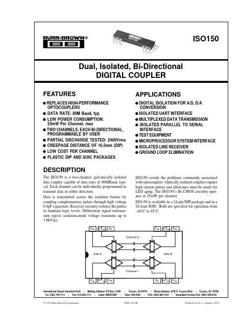
International Airport Industrial Park • Mailing Address: PO Box 11400 •Tucson, AZ 85734 • Street Address: 6730 S. Tucson Blvd. • Tucson, AZ 85706 Tel: (520) 746-1111 • Twx: 910-952-1111 • Cable: BBRCORP • Telex: 066-6491 • FAX: (520) 889-1510 • Immediate Product Info: (800) 548-6132© 1993 Burr-Brown Corporation PDS-1213B Printed in U.S.A. August, 19942®ISO150The information provided herein is believed to be reliable; however, BURR-BROWN assumes no responsibility for inaccuracies or omissions. BURR-BROWN assumes no responsibility for the use of this information, and all use of such information shall be entirely at the user’s own risk. Prices and specifications are subject to change without notice. No patent rights or licenses to any of the circuits described herein are implied or granted to any third party. BURR-BROWN does not authorize or warrant any BURR-BROWN product for use in life support devices and/or systems.SPECIFICATIONST A = +25°C, V S = +5V unless otherwise noted.ISO150AP, AUNOTES: (1) All devices receive a 1s test. Failure criterion is ≥5 pulses of ≥5pC. (2) The voltage rate-of-change across the isolation barrier that can be sustained without data errors. (3) Logic inputs are HCT-type and thresholds are a function of power supply voltage with approximately 0.4V hystersis—see text. (4) Supply current measured with both tranceivers set for the indicated mode. Supply current varies with data rate—see typical curves. (5) Calculated from the maximum Pulse Width Distortion (PWD), where Data Rate = 0.3/PWD. (6) Propagation time measured from V IN = 1.5V to V O = 2.5V. (7) The difference in propagation time of channel A and channel B in any combination of transmission directions. (8) The difference between progagation time of a rising edge and a falling edge.PARAMETERCONDITION MIN TYPMAXUNITS ISOLATION PARAMETERS Rated Voltage, Continuous 60Hz 1500Vrms Partial Discharge, 100% Test (1)1s, 5pC2400Vrms Creepage Distance (External)DIP—“P” Package 16mm SOIC—“U” Package 7.2mm Internal Isolation Distance0.10mm Isolation Voltage Transient Immunity (2) 1.6kV/µs Barrier Impedance >1014 || 7Ω || pF Leakage Current240Vrms, 60Hz 0.6µArms DC PARAMETERSLogic Output Voltage, High, V OHI OH = 6mA V S –1V S V Low, V OLI OL = 6mA 00.4V Logic Output Short-Circuit Current Source or Sink30mA Logic Input Voltage, High (3)2V S V Low (3)00.8V Logic Input Capacitance 5pF Logic Input Current<1nA Power Supply Voltage Range (3)35 5.5V Power Supply Current (4) Transmit Mode DC 0.001100µA 50MBaud 14mA Receive ModeDC 7.210mA 50MBaud 16mA AC PARAMETERS Data Rate, Maximum (5)C L = 50pF 5080MBaud Data Rate, Minimum DC Propagation Time (6)C L = 50pF 202740ns Propagation Delay Skew (7)C L = 50pF 0.52ns Pulse Width Distortion (8)C L = 50pF 1.56ns Output Rise/Fall Time, 10% to 90%C L = 50pF914ns Mode Switching Time Receive-to-Transmit 13ns Transmit-to-Receive 75ns TEMPERATURE RANGE Operating Range –4085°C Storage–40125°C Thermal Resistance,θJA75°C/W®3ISO150ABSOLUTE MAXIMUM RATINGSStorage Temperature .........................................................–40°C to +125°C Supply Voltages, V S ......................................................................–0.5 to 6V Transmitter Input Voltage, V I .............................................–0.5 to V S + 0.5V Receiver Output Voltage, V O .............................................–0.5 to V S + 0.5V R/T X Inputs.........................................................................–0.5 to V S + 0.5V Isolation Voltage dV/dt, V ISO ............................................................500kV/µs D X Short to Ground......................................................................Continuous Junction Temperature, T J ....................................................................175°C Lead Temperature (soldering, 10s).....................................................260°C 1.6mm below seating plane (DIP package).........................................300°CPACKAGE INFORMATION (1)PACKAGE DRAWINGMODEL PACKAGE NUMBERISO150AP 24-Pin Single-Wide DIP243-1ISO150AU28-Lead SOIC217-2NOTE: (1) For detailed drawing and dimension table, please see end of data sheet, or Appendix D of Burr-Brown IC Data Book.PIN CONFIGURATIONTOP VIEWDIP24 23 22 15 14 131 2 310 11 12D 1A R/T 1A V SA G B R/T 1B D 1B D 2A R/T 2A G A V SBR/T 2B D 2BPIN DESCRIPTIONSNAMEFUNCTIOND 1AData in or data out for transceiver 1A. R/T 1A held low makes D 1A an input pin.R/T 1A Receive/Transmit switch controlling transceiver 1A.V SA+5V supply pin for side A which powers transceivers 1A and 2A.G B Ground pin for transceivers 1B and 2B.R/T 1B Receive/Transmit switch controlling transceiver 1B.D 1B Data in or data out for transceiver 1B. R/T 1B held low makes D 1B an input pin.D 2B Data in or data out for transceiver 2B. R/T 2B held low makes D 2B an input pin.R/T 2B Receive/Transmit switch controlling D 2B .V SB +5V supply pin for side B which powers transceivers 1B and 2B.G A Ground pin for transceivers 1A and 2A.R/T 2A Receive/Transmit switch controlling transceiver 2A.D 2AData in or data out for transceiver 2A. R/T 2A held low makes D 2A in input pin.ELECTROSTATICDISCHARGE SENSITIVITYThis integrated circuit can be damaged by ESD. Burr-Brown recommends that all integrated circuits be handled with ap-propriate precautions. Failure to observe proper handling and installation procedures can cause damage.ESD damage can range from subtle performance degradation to complete device failure. Precision integrated circuits may be more susceptible to damage because very small parametric changes could cause the device not to meet its published specifications.4®ISO150TYPICAL PERFORMANCE CURVEST A = +25°C, V S = +5V unless otherwise noted.SUPPLY CURRENT PER CHANNELvs TEMPERATURETemperature (°C)–606 54 3 2 1–40–2020406080100120140S u p p l y C u r r e n t (m A)NORMALIZED RISE/FALL TIME vs TEMPERATURE1.61.51.41.31.21.11.0.9–60–40–2020406080100120140Temperature (°C)R e l a t i v e t r , t fSUPPLY CURRENT PER CHANNELvs SUPPLY VOLTAGE54321123456Supply Voltage, V S (V)S u p p l y C u r r e n t(m A )0POWER CONSUMPTION PER CHANNEL vs FREQUENCY Frequency (Hz)100k1M10M100MP o w e r (m W )S u p p l y C u r r e n t (m A )50 403020 100108642 0TYPICAL RISE AND FALL TIMES vs CAPACITIVE LOADvs SUPPLY VOLTAGE100806040200100200300400500Capacitive Load (pF)t r , t f (n s )PROPAGATION DELAY vs SUPPLY VOLTAGE4540353025202.53.0 3.54.0 4.55.0 5.5Supply Voltage, V S (V)P r o p a g a t i o n D e l a y (n s)®5ISO150TYPICAL PERFORMANCE CURVES (CONT)T A = +25°C, V S = +5V unless otherwise noted.ISOLATION VOLTAGE vs FREQUENCY10k 2.1k 1k1001011k10k100k1M10M100MFrequency (Hz)P e a k I s o l a t i o n V o l t a g e (V )PULSE WIDTH DISTORTIONvs TEMPERATURETemperature (°C)–605 4 3 2 1 0–40–2020406080100120140P u l s e W i d t h D i s t o r t i o n , P W D (n s)OUTPUT VOLTAGE vs LOGIC INPUT VOLTAGE5432100.5 1.0 1.5 2.0V IN (V)V O U T (V)PROPAGATION DELAY vs TEMPERATURE6050403020100–60–40–2020406080100120140Temperature (°C)P r o p a g a t i o n D e l a y , t P D (n s )LOGIC INPUT THRESHOLD VOLTAGEvs SUPPLY VOLTAGE2.01.81.61.41.21.00.80.60.40.202.02.53.03.54.04.55.05.56.0Supply Voltage, V SS (V)V I N (V)ISOLATION LEAKAGE CURRENT vs FREQUENCY100m10m1m 100µ10µ1µ100n1101001k 10k100k1MFrequency (Hz)L e a k a g e C u r r e n t (A r ms )6®ISO150TYPICAL PERFORMANCE CURVES (CONT)T A = +25°C, V S = +5V unless otherwise noted.ISOLATION BARRIERData is transmitted by coupling complementary logic pulses to the receiver through two 0.4pF capacitors. These capaci-tors are built into the ISO150 package with Faraday shield-ing to guard against false triggering by external electrostatic fields.The integrity of the isolation barrier of the ISO150 is verified by partial discharge testing. 2400Vrms, 60Hz, is applied across the barrier for one second while measuring any tiny discharge currents that may flow through the barrier. These current pulses are produced by localized ionization within the barrier. This is the most sensitive and reliable indicator of barrier integrity and longevity, and does not damage the barrier. A device fails the test if five or more current pulses of 5pC or greater are detected.FIGURE 1. Basic Operation Diagram.Conventional isolation barrier testing applies test voltage far in excess of the rated voltage to catastrophically break down a marginal device. A device that passes the test may be weakened, and lead to premature failure.APPLICATIONS INFORMATIONFigure 1 shows the ISO150 connected for basic operation.Channel 1 is configured to transmit data from side B to A.Channel 2 is set for transmission from side A to B. The R/T pins for each of the four transceivers are shown connected to the required logic level for the transmission direction shown. The transmission direction can be controlled by logic signals applied to the R/T pins. Channel 1 and 2 can be independently controlled for the desired transmission direction.TYPICAL INSULATION RESISTANCE vs TEMPERATURE 101610151014101310121011101020406080100120140160180Temperature (°C)I s o l a t i o n R e s i s t a n c e (Ω)®7ISO150LOGIC LEVELSA single pin serves as a data input or output, depending on the mode selected. Logic inputs are CMOS with thresholds set for TTL compatibility. The logic threshold is approxi-mately 1.3V with 5V supplies and with approximately 400mV of hysteresis. Input logic thresholds vary with the power supply voltage. Drive the logic inputs with signals that swing the full logic voltage swing. The ISO150 will use somewhat greater quiescent current if logic inputs do not swing within 0.5V of the power supply rails.In receive mode, the data output can drive 15 standard LS-TTL loads. It will also drive CMOS loads. The output drive circuits are CMOS.POWER SUPPLYSeparate, isolated power supplies must be connected to side A and side B to provide galvanic isolation. Nominal rated supply voltage is 5V. Operation extends from 3V to 5.5V.Power supplies should be bypassed close to the device pins on both sides of the isolation barrier.The V S pin for each side powers the transceivers for both channel 1 and 2. The specified supply current is the total of both transceivers on one side, both operating in the indicated mode. Supply current for one transceiver in transmit mode and one in receive mode can be estimated by averaging the specifications for transmit and receive operation. Supply current varies with the data transmission rate—see typical curves.POWER-UP STATEThe ISO150 transmits information across the barrier only when the input-side data changes logic state. When a trans-ceiver is first programmed for receive mode, or is powered-up in receive mode, its output is initialized “high”. Subse-quent changes of data applied to the input side will cause the output to properly reflect the input side data.SIGNAL LOSSThe ISO150’s differential-mode signal transmission and careful receiver design make it highly immune to voltage across the isolation barrier (isolation-mode voltage). Rapidly changing isolation-mode voltage can cause data errors. As the rate of change of isolation voltage is increased, there is a very sudden increase in data errors. Approximately 50% of ISO150s will begin to produce data errors with isolation-mode transients of 1.6kV/µs. This may occur as low as 500V/µs in some devices. In comparison, a 1000Vrms, 60Hz isolation-mode voltage has a rate of change of approximately 0.5V/µs.Still, some applications with large, noisy isolation-mode voltage can produce data errors by causing the receiver output to change states. After a data error, subsequent changes in input data will produce correct output data.PROPAGATION DELAY AND SKEWLogic transitions are delayed approximately 27ns through the ISO150. Some applications are sensitive to data skew—the difference in propagation delay between channel 1 and channel 2. Skew is less than 2ns between channel 1 and channel 2. Applications using more than one ISO150 must allow for somewhat greater skew from device to device.Since all devices are tested for delay times of 20ns min to 40ns max, 20ns is the largest device-to-device data skew.MODE CHANGESThe transmission direction of a channel can be changed “on the fly” by reversing the logic levels at the channel’s R/T pins on both side A and side B. Approximately 75ns after the transceiver is programmed to receive mode its output is initialized “high”, and will respond to subsequent input-side changes in data.STANDBY MODEQuiescent current of each transceiver circuit is very low in transmit mode when input data is not changing (1nA typi-cal). To conserve power when data transmission is not required, program both side A and B transceivers for trans-mit mode. Input data applied to either transceiver is ignored by the other side. High speed data applied to either trans-ceiver will increase quiescent current.CIRCUIT LAYOUTThe high speed of the ISO150 and its isolation barrier require careful circuit layout. Use good high speed logic layout techniques for the input and output data lines. Power supplies should be bypassed close to the device pins on both sides of the isolation barrier. Use low inductance connec-tions. Ground planes are recommended.Maintain spacing between side 1 and side 2 circuitry equal or greater than the spacing between the missing pins of the ISO150 (approximately 16mm for the DIP version). Sockets are not recommended.8®ISO150FIGURE 2. Isolated RS-485 Interface.®9ISO150F IG U R E 3. I S O 150 a n d A D S 7807 i s U s e d t o R e d u c e C i r c u i t N o i s e i n a M i x e d S i g n a l A p p l i c a t i o n .元器件交易网。
弱电线规格缆型号图片及说明大全
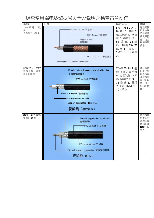
经常使用弱电线缆型号大全及说明之杨若古兰创作名称图例暗示方法用处SYV系列75欧姆实芯聚乙烯绝缘SYV 75-5-1(A、B、C) S: 射频Y:聚乙烯绝缘V:聚氯乙烯护套A:64编B:96编C:128编75:75欧姆5:线径为5MM 1:代表单芯通经常使用于电视监控零碎的视频传输,适合视频图像传输SYWV(Y)、SYKV 有线电视、宽带网公用电缆SYWV 75-5-1 S: 射频Y:聚乙烯绝缘W:物理发泡V:聚氯乙烯护套 75:75欧姆5:线缆外径为5MM 1:代表单芯通经常使用于卫星电视传输和有线电视传输等,适合射频传输.RG-58--96#-镀锡铜编织-50欧通经常使用于弱电视频图像传输或HFC收集等.AVVR或RVV 护套线RVV(227IEC52/53)聚氯乙烯绝缘软电缆RVV 和RVVP 里面采取的线为多股细铜丝构成的软线,即RV线构成. 通经常使用于弱电电源供电等.AVVR或RVV 圆形双绞护套线RVV(227IEC52/53)聚氯乙烯绝缘软电缆RVV-暗示铜芯聚氯乙烯绝缘聚氯乙烯护套圆形连接软电缆.适用于楼宇对讲、防盗报警、消防、主动抄表等工程.通经常使用于弱电电源供电等.RVVP-暗示软铜芯绞合圆型聚氯乙烯绝缘绝缘聚氯乙烯护套软电线.适用于楼宇对讲、防盗报警、消防、主动抄表等工程RVVP2*32/0.2 RVV2*1.0 BVR R: 软线 VV:双层护套线 P屏蔽RVB扁型无护套软电线或电缆AVRB 通经常使用于布景音乐和公共广播,也可做弱电供电电源线.RVS-暗示铜芯聚氯乙烯绞型连接电线.经常使用于家用电器、小型电动工具、仪器仪表、控制零碎、广播音响、消防、照明及控制用线. ZR: 阻燃R: 软线S:双绞线通经常使用于公共广播零碎/布景音乐零碎布线,消防零碎布线.RIB YXB音箱连接线(发烧线、金银线)用于功放机输出至音箱的接线.BV暗示单铜芯聚氯乙烯普通绝缘电线,无护套线BV4单铜芯聚氯乙烯绝缘电线,铜芯截面面积4平方毫米.红色,黄色,蓝色,绿色,黑色,黄绿色(地线)用于弱电供电电源线,普通适合做供电电流较大的骨干电源供电.适用于交流电压450/750V及以下动力安装、日用电器、仪表及电信设备用的电线电缆.BVR-暗示聚氯乙烯绝缘,铜芯(软)布电线,经常简称软线.因为电线比较柔软,经经常使用于电力拖动中和电机的连接和电线常有轻微挪动的场合BVV-暗示铜芯聚氯乙烯绝缘聚氯乙烯圆型护套电缆,铜芯(硬)布电线.经常简称护套线,单芯的是圆的,双芯的就是扁的,经经常使用于明装电线.ZR-BVV 3x6.0暗示3根截面6平方毫米的铜芯聚氯乙烯绝缘聚氯乙烯圆型护套电缆.KVV 和KVVP 里面采取的线为单股粗铜丝构成的硬线,即BV线构成.BVVB-暗示铜芯聚氯乙烯绝缘聚氯乙烯平型护套电缆.适用于请求机械防护较高、湿润等场合可明敷或暗敷.VV(VLV)-暗示铜(铝)芯聚氯乙烯绝缘聚氯乙烯护套电力线缆,NH-VV 3x70+2X35暗示3根截面积70mm2铜芯+2根35mm2铜芯的耐火聚氯乙烯绝缘聚氯乙烯护套电力线缆.适用于敷设在室内、隧道、及沟管中,不克不及承受机械外力的感化,可直接埋地敷设.铜芯聚氯乙烯绝缘屏蔽聚氯乙烯护套软电缆只是内部截面小于0.75平方毫米的名称为AVVR,大于等于0.75平方毫米的名称为RVVP.电压300V/300V 2-24芯例如:RVVP2*线径,RVVP3*线径,RVVP5*线径......带屏蔽形,通经常使用于弱电旌旗灯号控制及旌旗灯号传输,可防止干扰.仪器、仪表、对讲、监控、控制安装UTP:局域网电缆网线、收集线传输电话、计算机数据、防火、防盗保安零碎、智能楼宇信息网计算机收集线,有5类,6类之分,有屏蔽与不屏蔽之分HBV适用于室内外电话安装用线RVB 2X1/0.4电话线适用于室内外电话安装用线AV线(也叫:音视频线)2C-75-33C-75-3用于音响设备,家用影视设备音频和视频旌旗灯号连接.HTP咪线(也叫:话筒线)连接话筒与功放机.HYA、1.大对数通信电缆2.小对数通信电缆HYV因防水功能差现已淘汰,被具有挡潮功能的HYA代替.1.通经常使用于室外通讯主接线箱,普通对数数百户2.通经常使用于室外通讯分接线箱/或建筑物内楼层分线箱,普通撑持数十户SYXV75-5 电梯电缆用于随电梯行走的电视监控公用线材,内含视频线、电源线、钢丝VGA、RGB显示器线电缆的型号由八部分构成:一、用处代码-不标为电力电缆,K为控制缆,P为旌旗灯号缆;二、绝缘代码-Z油浸纸,X橡胶,V聚氯乙稀,YJ交联聚乙烯三、导体材料代码-不标为铜,L为铝;四、内护层代码-Q铅包,L铝包,H橡套,V聚氯乙稀护套五、派生代码-D不滴流,P干绝缘;六、外护层代码七、特殊产品代码-TH湿热带,TA干热带;八、额定电压-单位KV专业线缆产品在弱电工程中的俗称一、同轴电缆、视频电缆、视频线、同轴线、监控线、监控电缆、-2线、-3线、-5线、-7线、-9线、-12线、两兆线、对录线、音视频线、屏蔽线上述俗称可能涵盖的专业产品规格、型号:1、SYV75-2、SYV75-3、SYV75-5、SYV75-7、SYV75-9、SYV75-12、2、RG58、RG59、3D-2V、5D-2V、3C-2V、5C-2V、SYV75-2×4、SYV75-2×8、SYV75-2×16二、同轴电缆、有线电视电缆、有线电视线、射频电缆、射频线、物理发泡同轴电缆、发泡线、馈线、-5线、-7线、-9线、-12线、上述俗称可能涵盖的专业产品规格、型号:1、SYWV75-5、SYWV75-7、SYWV75-9、SYWV75-12、SYWLV75-7、SYWLV75-9、SYWLV75-12、2、SYWV75-5(2P/4P)、SYWV75-7(2P/4P)、SYWV75-9(2P/4P)、SYWV75-12(2P/4P)、3、RG59、RG6、RG7、RG11、三、电源线、护套线、多芯线、软线、控制线、旌旗灯号线、控制电缆、旌旗灯号电缆、控制线缆、旌旗灯号线缆、上述俗称可能涵盖的专业产品规格、型号:1、AVVR2ײ、AVVR2ײ、RVV2ײ、RVV2ײ、RVV2ײ、RVV2ײ、RVV2ײ、RVV2ײ、RVV2ײ或更大平方2、AVVR3ײ、AVVR3ײ、RVV3ײ、RVV3ײ、RVV3ײ、RVV3ײ、RVV3ײ、RVV3ײ、RVV3ײ或更大平方3、RVVP 2ײ、RVVP 2ײ、RVVP2ײ、RVVP2ײ、RVVP2ײ、RVVP2ײ、RVVP2ײ、RVVP2ײ、RVVP2ײ或更大平方4、KVV2ײ、KVV2ײ、KVV2ײ、KVV2ײ、KVV2ײ、KVV2ײ、KVV2ײ或更大平方5、KVV3ײ、KVV3ײ、KVV3ײ、KVV3ײ、KVV3ײ、KVV3ײ、KVV3ײ或更大平方6、RV0.3 mm²、RV 0.5 mm²、RV 0.75 mm²、²、²、²、²、²、²、²、或更大平方7、RVVB 2ײ、RVVB 2ײ、RVVB 2ײ、RVVB 2ײ、RVVB 2ײ、RVVB 2ײ、RVVB 2ײ、RVVB 2ײ、RVVB 2ײ或更大平方四、电源线、控制线、控制线缆、控制电缆、旌旗灯号线、旌旗灯号线缆、旌旗灯号电缆、屏蔽线、屏蔽线缆、屏蔽电缆、上述俗称可能涵盖的专业产品规格、型号:1、RVVP 2ײ、RVVP 2ײ、RVVP2ײ、RVVP2ײ、RVVP2ײ、RVVP2ײ、RVVP2ײ、RVVP2ײ、RVVP2ײ或更大平方2、RVVP 3ײ、RVVP 3ײ、RVVP3ײ、RVVP3ײ、RVVP3ײ、RVVP3ײ、RVVP3ײ、RVVP3ײ、RVVP3ײ或更大平方3、或更多芯数的RVVP系列线缆4 、KVVP 2ײ、KVVP 2ײ、KVVP2ײ、KVVP2ײ、KVVP2ײ、KVVP2ײ、KVVP2ײ、KVVP2ײ、KVVP2ײ或更大平方5、KVVP 3ײ、KVVP 3ײ、KVVP3ײ、KVVP3ײ、KVVP3ײ、KVVP3ײ、KVVP3ײ、KVVP3ײ、KVVP3ײ或更大平方6、或更多芯数的KVVP系列线缆7、RVVSP 2ײ、RVVSP 2ײ、RVVSP2ײ、RVVSP2ײ、RVVSP2ײ、RVVSP2ײ、RVVSP2ײ、RVVSP2ײ、RVVSP2ײ或更大平方/更多芯数8、RVVS 2ײ、RVVS 2ײ、RVVS2ײ、RVVS2ײ、RVVS2ײ、RVVS2ײ、RVVS2ײ、RVVS2ײ、RVVS2ײ或更大平方/更多芯数五、双绞线、花线、麻花线、S型双绞线上述俗称可能涵盖的专业产品规格、型号:RVS 2ײ、RVS 2ײ、RVS 2ײ、RVS 2ײ、RVS 2ײ、RVS 2ײ、RVS 2ײ、RVS 2ײ、RVS 2ײ或更大平方六、铜线、硬线、黄绿线、地线、零线、火线、接地线、平方线、平方线、4平方线、6平方线、10平方线上述俗称可能涵盖的专业产品规格、型号:1、BV 0.75 mm²、²、²、²、²、²、²、²、或更大平方2、BVVB 2ײ、BVVB 2ײ、BVVB 2ײ、BVVB 2ײ、BVVB 2ײ、BVVB 2ײ或更大平方七、音频线、音箱线、音响线、金银线、话筒线、喇叭线、广播线、发烧线、布景音乐线、公共广播线上述俗称可能涵盖的专业产品规格、型号:1、YXB 2ײ、YXB 2ײ、YXB 2ײ、YXB 2ײ、YXB 2ײ、YXB 2ײ、YXB 2ײ、YXB 2ײ、YXB 2ײ或更大平方2、YXB 2×20支、YXB 2×30支、YXB 2×50支、YXB 2×70支、YXB 2×100支、YXB 2×150支、YXB 2×200支、YXB 2×300支、YXB 2×630支或更多芯数3、RVVSP 2ײ、RVVSP2ײ、RVVSP 2ײ、RVVSP 2ײ、RVVSP 2ײ、RVVSP 2ײ、RVVSP 2ײ、RVVSP 2ײ、RVVSP 2ײ或更大平方、更多芯数4、RVVS2ײ、RVVS2ײ、RVVS2ײ、RVVS2ײ、RVVS2ײ、RVVS2ײ、RVVS2ײ、RVVS2ײ、RVVS2ײ或更大平方、更多芯数5、HTP 2×20芯、HTP 2×27芯、HTP 2×37芯、HTP 2×48芯、HTP 2×60芯、HTP 3×20芯、HTP 3×27芯、HTP 3×37芯、HTP 3×48芯、HTP 3×60芯、或更多芯数八、电话线、并线、耳机线上述俗称可能涵盖的专业产品规格、型号:RVB 2ײ、RVB 2ײ、RVB 2ײ、RVB 2ײ或更大平方九、RGB线、RGB电缆、VGA线、VGA电缆、3+4电缆、3+6电缆、3+9电缆、5+5电缆、十、电梯线、电梯公用线、电梯公用电缆、电梯监控线、电梯监控电缆上述俗称可能涵盖的专业产品规格、型号:TV-TV2P、TV-TV2P、TVVB-TV-3-R、TVVB-TV-3-G、TVVB-TV-5-G、十一、弱电线、弱电线缆、安防线缆、监控线缆、消防线缆、报警线缆、安防线、监控线、消防线、报警线、阻燃线、耐火线、地埋线、架空线、架空电缆、地埋电缆、阻燃电缆、耐火电缆、安防电缆、监控电缆、上述俗称可能涵盖的专业产品规格、型号:所有线缆型号前加前缀,如ZR、NH等十二、接插件、视频头、音频头、莲花头、同轴电缆连接器、Q9头、BNC接头、F头、双通、纵贯、三通、视频双通、视频三通、大二声接头、单声接头、双声接头、接头、接头、卡侬头、话筒头上述俗称可能涵盖的专业产品规格、型号:Q9J 、Q9K、BNCJ、BNCK、FJ、FK、KK、KJK、、6.35J2/J3/K2/K3、-1、-2、-3、-4、-5、-7、-9、-12、J3P/K3P、J3PW/K3PW、L16、SL16、十三、双绞线、网线、收集线、五类线、超五类线、六类线、收集电缆、计算机线、计算机电缆、光纤、光缆、三类大对数电缆、五类大对数电缆、配线架、理线架、模块、面板、跳线、成型跳线、尾纤、机柜、适配器、语音模块、数据模块、视频模块、物业模块、信息模块、打线、压线工具上述俗称可能涵盖的专业产品规格、型号:UTP电缆、、、具体型号/规格每个厂家不尽不异.介绍几种线缆的区别RVV 与 KVV、 RVVP 与 KVVP 其参考尺度(JB 8734.5-1998)区别:RVV 和RVVP 里面采取的线为多股细铜丝构成的软线,即RV线构成.KVV 和KVVP 里面采取的线为单股粗铜丝构成的硬线,即BV 线构成.作为KVV和KVVP的延长即为KYJV和KYJVP,改变就是在KYJV和KYJVP所采取的绝缘材料是硅烷交联绝缘料.AVVR 与 RVVP区别:东西一样,只是内部截面小于0.75平方毫米的名称为AVVR,大于等于0.75平方毫米的名称为RVVP.SYV 与 SYWV其参考尺度(YD/T1174-2001,YD/T1175-2001)区别: SYV是视频传输线, 用聚乙烯绝缘.SYWV是射频传输线,物理发泡绝缘.用于有线电视.RVS 与RVV 2芯区别: RVS为双芯RV线绞合而成,没有外护套,用于广播连接.RVV 2芯线直放成缆,有外护套,用于电源,控制旌旗灯号等方面YZ、YZW与YC、YCW其参考尺度(JB 8735-1998):区别:YZ、YZW是中型橡套软电缆,用于各种挪动电器设备和工具.电压等级为300/500V.YC、YCW是重型橡套软电缆,用于各种挪动电器设备,能够承受较大的机械外力感化.电压等级为450/750V.且在导体截面相等前提下,YC、YCW要比YZ、YZW的护套厚度大.估算电缆线径|截面积|分量、一、估算铜、铁、铝线的分量(kg/km)分量=截面积×比重 S=截面积(mm2)1. 铜线 W=9S W=分量(kg)2. 铝线 W=3S d=线径(mm)3. 铁丝 W=8S二、按线径估算分量(kg/km)≈7d2≈2d2≈6d2三、估算线径和截面积S=0.785d2如何拔取导体截面首先计算负荷距(架空线)负荷距=功率×长度 =PL P=功率(kw) L=长度(km)例:xx车间与配电房变压器相距200m,动力负荷200kw,问须要铜芯线多大平方?如改成铝芯线,须要多大平方?先计算负荷距=200×0.2=40kw/km因为根据“铜线:每千瓦公里用2.5mm2,铝线:每千瓦公里用4mm2”铜线 40×2.5=100mm2 实际选用120mm2.铝线 40×4=160mm2 实际选用185mm2.铝线计算截面公式实际选用185mm2Δu是电压损失百分数(答应电压损失是额定电压的4%)普通是5%导线截面积计算公式(导线距离/压降/电流关系)铜线 S=IL÷×U)铝线 S=IL÷(34×U)I-导线中通过的最大电流(A); L-导线长度(m);U-答应的压降(V);S-导线的截面积(平方毫米)。
玻纤增强热塑性聚丙烯片材完全手册(ppt 16页)

•在用于承载重物的区域,可以设计凹形筋来加强刚性。 •在设计凹形筋时,筋的外部宽度必须小于筋的高度。 •如果GFP片材加热变厚的厚度大于筋的深度,可以设计较大的尺寸。
华江科技
凹形筋 D
≥D
其他加强
另外,应用于热塑性工业的一般加强技术都可以应用于GFP片材。
边缘加强
弯角
凹形筋
根据产品的克重和表面覆盖物,最小的外角半径非常重要。内角的半径与片材的克重无关,但跟 选择的表面覆盖物关系密切。
1999
CrewCab
1999
GFP片材已经被证明是一种成熟的产品。
GFP片材产品手册
内饰顶
尼桑Xterra内饰顶 (表面为织物)一次成型
与聚氨酯泡沫复合板相比的优点:
•可回收性 •优良的模压性能 •在气候循环测试中尺寸稳定性好 •符合环保要求,无气味和散发性良好
门板
•重量轻 •极好的承载性能 •极好的延展性(在-40℃ ) •一次成型 •设备费用低 •设计费用低
产品拉伸率
拉伸率可以被定义为:在模压产品最大深度和产品最小开口距离的比值。
•根据上面的定义,拉伸率小于等于1可以适用于所有的GFP片材。 •通过凸模拉伸,最大拉伸率可以达到1.5,否则必须小心。 •不推荐拉伸率2。
产品整理和切割
使用机械式剪切或有效的刀就可以切割片材。
可用下列不同方式整理和修饰片材: •模内冲压 •模具外二次冲压 •激光整理 •水切割整理
行李架
•重量轻 •根据承重能力可选择不同克重 •对于复杂设计具有极好的成型能力 •良好的隔音性能 •一次成型 •设备费用低
华江科技
GFP片材产品手册
华江科技
承载板
使用GFP片材ቤተ መጻሕፍቲ ባይዱ为中间层,表面使用符合要求的织物、聚丙烯发泡材料或地毯一次成型。
2015a 塑料材料技术标准20153新标准_图文
QMW 广东美的厨房电器制造有限公司企业标准QMW-J03.175-2015a 厨房电器塑料材料技术标准2015–03-01发布2015-04-01实施目次前言 (IV)1 范围 (1)2 规范性引用文件 (1)3 术语和定义 (1)4 技术要求 (1)4.1 外观及包装要求 (1)4.1.1 颗粒外形要求.................................................................14.1.2 颗粒均匀性要求............................................................14.1.3 颜色要求.....................................................................24.1.4 包装要求............................................................24.1.5 标示要求.................................................................24.1.6 运输与仓储要求 (2)4.1.7 材料的环保要求...............................................................24.1.8 材料的技术性能指标要求.......................................................24.2塑胶的原材料技术性能要求.........................................................24.2.1原材料的密度测试.............................................................24.2.2原材料的含水率测试...........................................................24.2.3原材料的灰份测试.............................................................24.2.4原材料的融熔指数的测试......................................................24.2.5原材料的热变形温度测试.......................................................24.2.6原材料的维卡软化温度测试.....................................................34.2.7原材料的阻燃特性测试.........................................................34.2.8原材料的冲击强度测试........................................................34.2.9原材料的拉伸强度测试.........................................................34.2.10原材料的断裂伸长率测试......................................................34.2.11原材料的弯曲强度测试........................................................34.2.12原材料的弯曲模量测试........................................................34.2.13原材料的材料收缩率测试......................................................44.2.14原材料球压温度测试..........................................................44.2.15原材料灼热丝起燃温度测试....................................................44.2.16原材料的100%二次料性能.....................................................44.2.17原材料的15%二次料+85%原料的性能............................................44.2.18原材料的30%二次料+70%原料的性能.............................................44.2.19原材料的样条残余应力的测试.................................................44.2.20原材料的相关认证要求........................................................44.3 原材料加工工艺参数要求........................................................54.3.1 原材料对机器的选择........................................................54.3.2 原材料的干燥工艺条件要求.....................................................54.3.3 原材料的注塑加工条件要求.....................................................5附录 A 《微波炉公司塑胶原材料及其技术性能指标》 (6)附录 B 《吸尘器公司塑胶原材料及其技术性能指标》 (6)附录 C 《微波炉公司塑胶原材料优选清单》 (7)附录 D 《吸尘器公司塑胶原材料优选清单》 (7)附录 E 《厨房电器事业部塑胶材料物性填写表格》 (8)附录 F 《原材料检验项目分类》 (9)前言本标准是根据GB/T 15497《企业标准体系技术标准体系》的要求,结合事业部现有产品平台开发的实际情况,制定本技术标准,作为厨房电器事业部塑胶原材料的检验依据。
塑料原材料牌号及用途明细表
塑料原材料牌号及用途明细表塑料原料牌号及应用通用塑料低密度聚乙烯 LDPE 型号产地熔指g/10min特性及用途LDPE-普通膜类LD100AC LD100 燕山石化 1.7-2.3用于农膜、收缩膜、透明膜、层压膜、共挤出多层膜及医用包装、各种包装袋、LLDPE的掺混料、注塑料;可用硅烷、过氧化物进行交联,用于动力电缆绝缘LD155 燕山石化 1.7-2 一般用途包装膜LD662 燕山石化1.9 适用于农膜、收缩膜、透明膜、层压膜、共挤出多层膜及医用包装、各种包装袋和LLDPE的掺混料LD600 燕山石化 2 适用于农膜、收缩膜、透明膜、层压膜、共挤出多层膜及医用包装、各种包装袋和LLDPE的掺混料LD617 燕山石化 2 适用于农膜、收缩膜、透明膜、层压膜、共挤出多层膜及医用包装、各种包装袋和LLDPE的掺混料LD160LD160AS燕山石化3-5 适用于衬里、透明膜、层压膜、超薄膜、铸膜、各种包装袋及注塑LD160BW 燕山石化 2 掺混,用于通用膜产品2102TN26 齐鲁石化2.1-2.9 通用膜料,适用于制作轻包装膜、农地膜等2436H 大庆石化 2 高透明薄膜、复合薄膜2426H 中海/扬巴大庆/兰化2 含爽滑剂、开口剂,可用作层压膜、深冷包装膜及购物袋等日用包装农用薄膜(棚膜)2426K 中海/扬巴大庆/兰化4 含爽滑剂、开口剂,可用作日用包装3026H扬巴大庆/兰化1.7-2.2 用于收缩薄膜、层压膜FD0274 卡塔尔 2.4 具有优秀的光泽度,用于生产低中强度的挤出膜,含有爽滑剂和开口剂。
LDPE-透明膜类LD104 燕山石化1.7-2.3 用于收缩膜、透明膜、层压膜、共挤出多层膜及购物袋、包装袋、医用包装并可用硅烷交联作动力电缆绝缘LD105 燕山石化 2 在LD104基础上改进。
用于收缩膜、透明膜、层压膜、共挤出多层膜及购物袋、包装袋、医用包装并可用硅烷交联作动力电缆绝缘QLT-04 齐鲁石化 2.4-3.6 高透明包装膜Q281 上海石化 2.8 用于吹塑、高透明轻膜5320 韩国韩华 2 用于薄膜、轻包装膜F222 日本宇部 2 用于一般包装薄膜、复合膜、冷冻膜200GG 马来西亚 2 用于一般包装用膜F210-6 新加坡TPC2 用于一般包装薄膜.530G 韩国三星 2.8 用于一般用途包装膜、收缩膜、农膜FD0474 卡塔尔 4 高透明度包装膜展示膜,洗涤膜,透明度优异,优异的加工性及延展性FB3000 韩国LG 3 用于一般包装用薄膜LDPE-收缩膜/重包装膜类LD163 燕山石化0.3 用于收缩膜LD165 燕山石化0.23-0.43 用于大棚膜、收缩膜及衬里、用硅烷交联动力电缆绝缘、通讯电缆外套、吹塑、管材LD150 燕山石化0.6-0.9 用于农膜、收缩膜、重包装膜、层压膜、共挤出多层膜及购物袋、冷冻袋、包装袋和用硅烷交联的动力电缆绝缘2100TN00 齐鲁石化0.25-0.3 用于重包装膜、收缩膜、大棚膜及电缆料2420D 中海/扬巴大庆/兰化0.3 用于小型吹塑、农膜、重包装1810D 扬巴/茂名大庆/兰化0.2-0.5 用于管道涂覆、电缆料、内衬、农膜、重载膜和重载收缩膜等1810E 大庆石化0.5 重包装、收缩、吹塑2423D 大庆石化0.3 重包装、农用薄膜2420F 中海/扬巴大庆/兰化0.7 用于小型吹塑、日用包装2426F 中海/扬巴大庆/兰化0.7 含爽滑剂、开口剂,可用作日用包装3020D 扬巴0.15-0.35 用于收缩膜、层压膜FB0300 韩国LG0.3 用于重包装膜FB3003 卡塔尔0.3 用于生产重包装膜,不含任何添加剂LDPE-注塑及薄膜类18D18D0大庆石化 1.5 适用于各种薄膜及小型制品1I2A 燕山石化 2 注塑级,可用作管材,板材,吹塑2420H 中海/扬巴大庆/兰化2 注塑级,用作日用包装2420K 中海/扬巴大庆/兰化4 注塑级,用作日用包装3025K 大庆石化 2 薄膜、复合薄膜1810H 扬-巴 1.3-1.8 注塑级,用作医药包装及表面保护膜1816H 扬-巴 1.3-1.8 注塑级,用作内衬2420H 中海/扬巴大庆/兰化1.7-2.2 注塑级,用作收缩薄膜、层压膜及购物袋3020H 中海/扬巴大庆/兰化1.7-2.2 注塑级,用作收缩薄膜、层压膜、表面保护膜及管道涂覆、医药包装3020K 中海/扬巴大庆/兰化3.4-4.6 注塑级,用作收缩薄膜、层压膜、表面保护膜及医药包装3026K 中海/扬巴大庆/兰化3.4-4.6 注塑级,用作收缩薄膜、层压膜及医药包装2420K 中海/扬巴大庆/兰化3.4-4.6 注塑级,用作收缩薄膜EB-853/72 巴西OPP 2.7 注塑级,一般包装用薄膜LDPE-高熔指注塑类LD615 燕山石化12-18 用于注塑、母料基料1810S 中海/扬巴大庆/兰化17-22 用于注塑2410T 中海/扬巴大庆/兰化33-39 用于注塑2410T 中海壳牌大庆石化36 用于注塑1I50A 燕山石化50 用于人造花、盆景LD400 燕山石化20-30 冰箱食品搁架、公路、铁路护栏粉末涂料原料、母粒用载体树脂MG70 卡塔尔70 具有优异的流动性和加工性,用于注塑生产及色母料制做LDPE-发泡类1F7B 燕山石化7 用于生产各种薄膜、农地膜、水果网套、母料基料LD605 燕山石化 4.5-7.5 用于发泡、注塑及薄膜LD607/608 燕山石化5-7 用于发泡、注塑及薄膜15803 俄罗斯2-2.5 用于壁厚为3mm以上的大型制品,如10升以上的容器和一般用途的薄膜及发泡产品10803 俄罗斯2-2.5 用于棚膜、小型注塑产品、发泡产品LDPE-电缆料类2102-TN00 齐鲁石化 2.1-2.9 适用于制作轻包装膜、发泡片材、电线电缆.LD100BW/LD200BW燕山石化 2.2 用于电缆料18E 大庆石化 1.8 用于电缆或发泡DJ210 上海石化 2.1 挤出级,用作交联电缆料DJ200A 上海石化 2 注塑级,用作交联电缆料2210H 大庆石化 2 中压电缆绝缘料2220H 扬-巴 1.8-2.2 注塑级,用作电缆料LDPE-涂层类1C10A 燕山石化10 用于涂层、编织袋及牛皮纸的涂覆等1C7A 燕山石化7 用于涂层、纺织袋的涂覆等1C7A-1 燕山石化7.2 可用于食品、药品以及液体无菌包装等领域。
CP1501中文资料
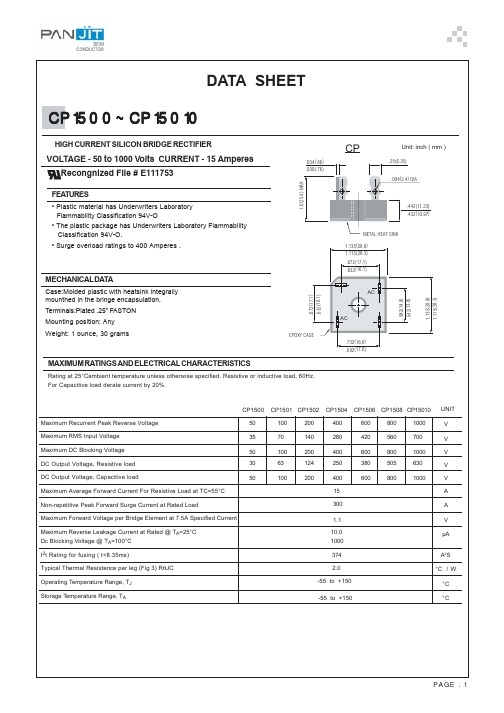
CP
.034(.86) .030(.76)
Unit: inch ( mm )
.25(6.35) .094(2.4) DIA
.442(11.23) .432(10.97)
METAL HEAT SINK 1.135(28.8) 1.115(28.3) .672(17.1) .632(16.1)
Fig. 3- OUTPUT CURRENT VS. AMBIENT TEMPERATURE RESISTIVE OR INDUCTIVE LOAD BRIDGE MOUNTED ON A 8" x 8" ALUMINUM PLATE 25"THICK
Fig. 4- POWER DISSIPATION VS.AVERAGE OUTPUT CURRENT RESISTIVE OR INDUCTIVE LOAD TJ=150 OC
40 30 20 15
AVERAGE OUTPUT CURRENT ,AMPERES
30
25
20
10 8 6 4
15
10
5 0 25 60 80 100 120
O
5
10
15
20
25
30
35
140
160
180
AVERGE OUTPUT CURRENT,AMPERES
AMBIENT TEMPERATURE, T A C
AC
AC
EPOXY CASE
.732(18.6) .692(17.6)
MAXIMUM RATINGS AND ELECTRICAL CHARACTERISTICS
Rating at 25°Cambient temperature unless otherwise specified. Resistive or inductive load, 60Hz. For Capacitive load derate current by 20%.
Mean Well RSP-150 电源说明书
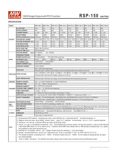
DC VOLTAGE RATED CURRENT
3.3V
5V
30A
30A
7.5V
12V
13.5V
15V
20A
12.5A
11.2A
10A
24V
27V
48V
6.3A
5.6A
3.2A
CURRENT RANGE
0 ~ 30A
0 ~ 30A
0 ~ 20A
0 ~ 12.5A 0 ~ 11.2A 0 ~ 10A
0 ~ 6.3A 0 ~ 5.6A 0 ~ 3.2A
※ Product Liability Disclaimer:For detailed information, please refer to https:///serviceDisclaimer.aspx
File Name:RSP-150-SPEC 2022-09-20
6.9
2-M4 L=4mm 117
16 49.5 99 119
4-M4(Both Sides) L=4mm
12.5 30
Terminal Pin No. Assignment
Pin No. Assignment Pin No.
1
AC/L
4,5
2
AC/N
6,7
3
FG
Assignment DC OUTPUT -V DC OUTPUT +V
SAFETY STANDARDS
UL62368-1, TUV BS EN/EN62368-1, BS EN/EN61558-1, BS EN/EN61558-2-16, EAC TP TC 004, CCC GB4943.1,
515说明

目录章节1.0 产品介绍1.1 说明1.2 技术规范2.0 安装2.1 开箱检查2.2 安装装配件2.3 各种管道的装配件2.3.1 PVC和CPVC管件2.3.2 不锈钢、镀锌和黄铜管件2.3.3 焊接管件2.4 流量传感器的安装3.0 运行原理4.0 故障查寻5.0 维护和维修6.0 附录6.1 备件清单6.2 可选附件/替换部件6.3 保证7.0 手册变化信息1.0产品介绍这本手册包括了Signet 515流量传感器、转换器的安装和运行说明、技术规范和指导。
请通读这本说明书,它将回答你关于这些传感器、转换器的几乎所有问题。
如果你需要更进一步的资料,请与你的Signet供货商联系。
1.1说明Signet浆轮式流量计和相应的Signet指示仪器用来测量管道中液体的流速。
流量传感器做得很坚固,并且水头损失很小。
它可以很容易地拆下来检查和清洗。
要使515能够正确运行,必须安装在Signet装配件上。
515需要安装在MK316装配件或MK319‘Wet-Tap’组件上。
当流量传感器被拆下来时,每一个Signet装配件都提供了一个塞子,用来封住装配件。
515有玻璃纤维增强的聚丙烯或PVDF(聚偏二氟乙烯)两种外壳,可供选择。
流量传感器的防泄漏是由两个可以很容易更换的标准的氟橡胶O型圈组成的(见图1)。
作为特殊场合,可以提供高度稳定的耐腐蚀的Kalrez O型圈。
参见6.1节(备件清单)。
浆轮包括4个用超声波焊接进PVDF叶片内的永久磁铁。
515有九种型号以适应不同的管道尺寸及应用(见表1)。
515聚丙烯的-PO,-P1,-P2型号用于标准应用。
PVDF -VO,-V1,-V2型号用于恶劣的场合。
所有515流量传感器的加长部分都是由CPVC制成的(氯化聚氯乙烯)。
-P3,-P4,-P5聚丙烯特殊加长型是与MK319‘Wet Tap’一起使用的(见表2)。
‘Wet Tap’是传感器和Signet装配件之间的接口(在线拆装隔阀)。
NOV 1-14英寸钢管配件数据表说明书

Data Sheet1-14 in. Fittings and Accessoriesmanufactured from both epoxy and vinyl ester resins. Thesefittings and adhesives provide the same corrosion resistance and temperature ratings as the compatible grade of pipe. Press molded fittings are manufactured from a resin-rich compound which is corrosion resistant throughout the fitting wall. Hand layup fittings have a 100 mil resin-rich corrosion barrier. Epoxy RB fittings are color-coded brown; Z-CORE fittings are dark green or black; CL for the most severe services, they are suitable for the broad range of chemicals shown in the Chemical Resistance Guide . All 1-14 in. fittings are available with either a socket fitting or flanged type connection for easy field assembly. Adapters to iron pipe threads are also available.Order by figure (Fig.) number prefixed with CL for vinyl ester, RB for epoxy and ZC for Z-Core followed by construction type (if applicable), diameter, and outlet sizes.Example: Fig. 34C HLU 3x2PM - Represents Press Molded Fittings HLU - Represents Hand Layup FittingsCentricast™ Piping SystemsIndexAccessories ..............................................................................................19Adhesives .................................................................................................18Assembled fitting dimensions .............................................................14Centriclamp .............................................................................................13Couplings ...................................................................................................3Crosses .....................................................................................................11Elbows ........................................................................................................7End caps .....................................................................................................4Flanges .......................................................................................................6Floor drains . (12)How to read flanged or reducer fittings .............................................17Laterals .....................................................................................................11Maintenance repair kits .........................................................................19Nipples .......................................................................................................3Pipe support/wear pad .........................................................................12Pressure ratings ........................................................................................2Reducers ....................................................................................................5Saddles .......................................................................................................4Special configuration . (17) (17)Tees ...........................................................................................................10Threaded adapters ..................................................................................3Threaded inserts (4)200200-220020012532002001254150150100615015010081501501001015015075121501507514125150-Pressure Rating of CL Vinyl Ester Fittings up to 200°F based on Weldfast™ CL-200 and/or CL-200QS Adhesive Uninsulated PipingReduce pressure by 25% for 175°F to 200°F operating temperatures.200200300--220020030012532002002001254150150150100615015015010081501501501001015015015075121501501507514125150150--Pressure Rating of RB Epoxy Fittings up to 225°F based on Weldfast ZC-275 Adhesive Uninsulated PipingFor insulated and/or heat traced piping systems, use 100% ofuninsulated piping recommendations up to 200°F and reduce these ratings 50% for 200°F to 250°F operating temperatures. For uninsulated CENTRICAST PLUS RB-2530 piping, reduce these ratings 30% for 225°F to 250°F operating temperatures.Pressure Rating of ZC Epoxy Fittings up to 225°F basedon Weldfast ZC-275 Adhesive Uninsulated Piping200200300--220020030012532002002001254150150150100615015015010081501501501001015015015075121501501507514125150150--For insulated and/or heat traced piping systems, use 100% of uninsulated piping recommendations up to 225°F and reduce these ratings 25% for 225°F to 275°F operating temperatures. For uninsulated ZC piping, reduce these ratings 25% for 250°F to 275°F operating temperatures.Note: Quotations for specially fabricated higher pressure fittings are available on request.AInner Coupling13-0.53-0.534- 1.044- 1.58-4.410-13.214-17.211.024 1.4342.06 6.5898.8101228180.5281.13 1.968 5.0180.5281.13 1.968 5.0Threaded Adapters2 1.0341.461.61*30.740.734 1.542.9Fig. 14 SocketFig. 29S*Iron Pipe Thread x Socket*Available on order only - nonreturnable. †CL weight, multiply by 1.07 for RB, 1.1 for ZC.Fig. 30 RSR Repair CouplingFig. 2 Iron Pipe Thread1 x blank*-0.1-0.22 x blank*-0.43 x blank*2-1.20.40.30.30.220.8Fig. 33S Insert0.924 1.244 3.7812.410*4215Fig. 13 Pipe SaddleNote: For Threaded Outlets or Cement Socket Outlets greater than one size reduction, see Assembled Fittings section. Figure 13 weights based on blank saddle. Saddles available in CL and RB only.* Available on order only - nonreturnable † CL weight, multiply by 1.07 for RB, 1.1 for ZC22XX0.4482XX2.6692X X4.810X X23.112XX32.8Fig. 33Insert SocketReducer inserts which reduce greater than two pipe sizes are available on order only.Reducer inserts 8 in. and larger which reduce greater than one pipe size may have areduced pressure rating. Consult factory for specific recommendations.2 x 110.30.220.93 x 2220.64 x 3230.76 x 222 3.56 x 424 2.28 x 227.48 x 337.18 x 6 3.510 x 2220.910 x 4417.910 x 613.812 x 2234.912 x 3333.112 x 622.912 x 816.912 x 1012.1Fig. 34C Concentric Tapered Socket, Hand LayupConstruction2 x 1632.01.23 x 26 1.94 x 22.64 x 3 2.96 x 3 6.88 x 41110.78 x 6119.510 x 81411.512 x 81617.214 x 121522.82 x 16 2.86 3.463 x 26 5.24 x 376 x 3910.18 x 41118.58 x 61120.210 x 81235.512 x 81446.914 x 12** Available on order only - nonreturnable (1) See Fig. 18 for flange dimensions.†CL weight, multiply by 1.07 for RB, 1.1 for ZCFig. 34F Concentric Tapered Socket+4 x 2511.54 x 354 1.66 x 4951 5.58 x 4529.58 x 617.310 x 62413.712 x 8162416.812 x 1014420.0Fig. 35C Eccentric Tapered Socket3 x 2 6.24 x 218.2 6 x 3910.06 x 49112.08 x 411216.18 x 611119.710 x 812135.212 x 814246.4Fig. 35F Eccentric Tapered FlangedFlanges5-1.1362.549 4.289.910161-1421-45.512-15 1.32 x 16 1.43 x 263.34 x 29 6 x 2117.66 x 3118.06 x 4118.88 x 217.68 x 416.08 x 613.410 x 816127.312 x 81617149.9Flanges meet O.D. bolt circle diameter, number of holes, and bolt hole diameter dimensions for ANSI B16.1 125 lb. cast iron sizes 1-72 in. and ANSI B16.5 lb. steel for 1 in.-24 in. diameters.* Available on order only - nonreturnable (1) See Fig. 18 for flange dimensions.† CL weight, multiply by 1.07 for RB, 1.1 for ZCFig. 18 and Fig. 18L * Flange SocketFig. 18R * Reducer Socket4.7625 + 1.5875Flange Lip+Fig. 18M* Flange Metric SocketFig. 22 Blind Flange251115851422.22534.9254-12 mm 401501101830.16338.1004-16 mm 5021651251850.8004-16 mm 8032001601830.16350.8008-16 mm 15062792412350.8008-20 mm 20083432352.38860.3258-20 mm 250104063502377.788106.36312-20 mm 300124834002377.788106.36312-20 mm10.65 1.2261.8363.06118.2816.6121917149.1Fig. 21/24/25* Van Stone Flange36124912Elbows0.63 2.44 3.5812.0Fig. 255C 90° Short Radius Elbow, SocketFig. 257C 90° Long Radius Elbow, Socket61.52 1.932.2493.6813.810422.81422441.0HLU ConstructionSizes 1 in. - 6 in. PM Construction 8 in. HLU Construction* Available on order only - nonreturnable (2) Maximum Iron Pipe Thread size = 1 in. † CL weight, multiply by 1.07 for RB, 1.1 for ZCFig 22S Iron Pipe TappedFig. 255S* 90 ° Short Radius Elbow, Flange x SocketFig. 255F 90 ° Short RadiusElbow, Flanged11.151.926 3.3365.1611682511.853.3264.4368.3681120.88936.412121719173.454.2265.24914.661117.11016152.612191719172.2Fig. 257F 90 ° Long Radius Elbow, FlangedFig. 257S* 90 ° Long Radius Elbow, Flange x Socket* Available on order only - nonreturnable ** Tolerance exception - Fig. 257F x 14 - A ±1⁄8 † CL weight, multiply by 1.07 for RB, 1.1 for ZC562.826 3.34998.561114.41016149.7121719165.214*2122105.112-1110.7333* 2.1665*7.0887.71212414144Fig. 265F 45° Short Radius Elbow, Flanged12.1265.43366.661120.38-23.812-171917714-2111512-111.326 3.23634.9611513.78--15.912-171914-57.514-214-7012-1Fig. 265S* 45° Elbow, Flange x Socket* Available on order only - nonreturnable † CL weight, multiply by 1.07 for RB, 1.1 for ZCFig. 265C 45° Short Radius Elbow, Socket275C x 10275C x 12A±Tolerance ExceptionB ±C±Fig. 275C Tee, Socket1570.84*80.9311 3.4413 5.36-8-1611.28--15.512--438.814--440.82967.6311612.6413919.06-8-161132.710-11-221619012-12-2419117125Fig. 275F Tee, Flanged11 3⁄161.52.2263.9 5.8367.010.66 -116819.327.58--22.228.912-191174-95140Fig. 275S* Tee, Flanged x Socket6 in. PM available in CL only* Available on order only - nonreturnable †CL weight, multiply by 1.07 for RB, 1.1 for ZC1/81/81/42 2.03 3.74118613.910451.712469.1267.64919.061132.7101611121219171152Note: Reducing Laterals and crosses are available on request.Fig. 266F* Lateral, Flanged* Available on order only - nonreturnable.† CL weight, multiply by 1.07 for RB, 1.1 for ZC4 5.5616815.7815.510445.6269.33613.961681157.5818971.712241219171170Fig. 266C Lateral SocketFig. 285C Cross, SocketFig. 285F* Cross, FlangedF I D GH AE BCin.in. + in. > 0Fig. 391 Pipe Support*Available on order only - nonreturnable.124346481214*Fig. 203 Sealable Floor DrainDP 316 SS insert 3 places on “D” bolt circleFig. 33C Reducer Insert required for 6x2, 6x3, 12x4 and 12x6 sizes.6 x 22676 x 4626712 x 481412 x 88814Floor Drain 203FD Equipment Drain203EDSealable Drain Standard ConfigurationsNote: Standard outlet straight socket. 2- 6 in. FNPT outlet available on request.Sealable Drain Dimensional Data21501505033331501507534261501501504418150125175448Fig. 36* End Adapter20.5350.76 2.2Fig. 38* SS Clamp310.747511.281215.5* Available on order only - nonreturnable.† CL weight, multiply by 1.07 for RB, 1.1 for ZCFig. 39* Blind Flange354682Physical Data0.72 x 14 1.33 x 2 1.64 x 2 2.76 x 4 5.48 x 47.810.81.13 2.64 3.6Assemble using Fig. 14 Socket Coupling and Fig. 33 Reducer BushingAssemble using Fig. 6S Adapter and Fig. 14 Socket Coupling2 2.04 4.96 6.510423.912433.9 1.82 2.54 6.569.3482XV XV XV X XV X V V S S 692XV XV XV XV XV XV W W S V S 810½2XV XV XV XV XV XV W W S V V S 1013½XV XV XV XV XV XV W W S V V V S X=Fabricated using Fig 13 Cement Socket Outlet Pipe Saddle and Fig 33SThreaded Bushing Insert.V=Fabricated using Fig 13 Cement Socket Outlet Pipe Saddle and Fig 33 Socket Reducer Bushing Insert.S=Standard Pipe Saddle, no fabrication needed.Fig. 244* Nipple Flange Iron Pipe ThreadFig. 13* Pipe SaddleXV=Fabricated using Fig 13 Cement Socket Outlet Pipe Saddle, Fig 33 Socket Reducer Bushing and Fig 33S Threaded Bushing Insert.W=Fabricated using Fig 13 Cement Socket Outlet Pipe Saddle and 2 or more Fig 33 Socket Reducer Bushing Inserts.Assemble using Fig. 18 Socket Flange and Fig. 6S Iron Pipe AdapterAssemble using Fig. 18 Socket Flange and Fig. 17 Pipe Stub* Available on order only - nonreturnable. † CL weight, multiply by 1.07 for RB, 1.1 for ZC24666118124574 x 366 x 49 6 x 4910 x 812 x 10161Fig. 265CR 45° Reducer, SocketFig. 265FR* 45° Reducer, Flanged233658--12--453 x 266 x 498 x 6-1112 x 10-161Assemble using Fig. 255C Elbow and Fig. 33 Reducer BushingAssemble using Fig. 257C Elbow and Fig. 33 Reducer BushingAssemble using Fig. 255C Elbow and Fig. 33 Reducer Bushing, Fig. 17 Pipe Stub and Fig. 18 Socket FlangeAssemble using Fig. 257C Elbow, Fig. 33 Reducer Bushing, Fig. 17 Pipe Stub and Fig. 18 Socket FlangeAssemble using Fig. 265C Elbow and Fig. 33 Reducer BushingAssemble using Fig. 265F Elbow and Fig. 33 Reducer Bushing, Pipe Stubs and Fig 18 Socket Flanges6 in. PM available in CL only * Available on order only - nonreturnable.35 1.74 2.28 6.3 148Fig. 37* Adapter Nipple6 in. PM available in CL only* Available on order only - nonreturnable.(3) Reductions beyond one pipe size for reduced pressure applications are available. (See Fig. 33)573 x 264 x 366 x 498 x 6-1110 x 8-12 x 10-161 Fig. 275CR* Reducer, SocketAssemble using Fig 275C and Fig 33 Reducer Bushing45° ELBOW Fig. 265C90° SHORT or LONG RADIUS ELBOWFig. 255CFig. 275CFig. 266C CROSS Fig. 285CA CB A BACBDAA CB1---1---348-12-10---12---14--18----Special Configuration FittingsContact NOV Fiber Glass Systems for Details• 2 in. thru 12 in. Long Turn Tee, Flanged, Fig 267F• Odd degree elbows, 15, 221/2, 30 & 60 degree • 2 in. thru 12 in. 45° Double Y Branch, Socket, Fig. 268C • 5D Socket & Flanged Elbows • 2 in. thru 12 in. 45° Double Y Branch, Flanged, Fig. 268F • Sump Fittings• 2 in. thru 12 in. 90° Double Y Branch, Socket, Fig. 269C • 4 in. thru 10 in. Reducing Lateral, Socket, Fig. 266CR • 2 in. thru 12 in. 90° Double Y Branch, Flanged, Fig. 269F• 2 in. thru 12 in. Fig 267F Long Turn Tee, Socket, Fig. 267CThe sequences illustrated should be used when describing fitting outlets. Drawings or sketches showing outlet types, locations, sizes and dimensional requirements are required for more complicated fitting configurations.Pipe Stop to Fittings’ Center Line DimensionsHow to Read Flanged or Reducing FittingsTEECROSS(A x B x C)(A x B x C x D)Order for Z-Core epoxy piping systems. Weldfast ZC-275 adhesive can also be used to bond RB and CL pipe and fittings. Usage should be limited to applications recommended for both Z-Core product and the pipe and fittings grade being used.Contents:Adhesive (Part A) Hardener (Part B)Wooden Stir Stick Plastic Putty KnifeFabrication Instructions108 2 in. connections 5 3 in. connections 3 4 in. connections 2 6 in. connections 18 in. connections 10 in. connections 12 in. connectionsWeldfast CL-200-QS Part “C”Accelerator used with WELDFAST CL-200 to provide a quick set vinyl ester adhesive. Joints fabricated with this quick set adhesive can be made and quickly cured in as little as one hour (at room temperature) compared to 24 hours (at room temperature) for conventional adhesives.Contents:Adhesive (Part A) CatalystWooden Stir Stick Plastic Putty Knife Fabrication Instructions Order for CL-2030 and CL-1520 vinyl ester piping systems.For complete instructions refer to fab Bulletin D4210 included ineach kit of WELDFAST CL-200.108 2 in. connections 5 3 in. connections 3 4 in. connections 2 6 in. connections 18 in. connections 10 in. connections 12 in. connections 14 in. connectionsWeldfast ZC-275 Epoxy Adhesive for Adhesive Socket Joints For complete instructions, refer to fab Bulletin D4090 included in each kit of WELDFAST ZC-275 Adhesive.Weldfast CL-2004 - 8 inches C 10 - 14 inches D 16 - 20 inchesESilicone Rubber Heat Blanket*Strap Clamp Kit*For Heat Curing 1-20 in. connections * Available on order only - nonreturnable.Fiber Glass Systems17115 San Pedro Avenue, Ste. 200, San Antonio, Texas 78232, USAPhone: 210 477 7500 Fax: 210 477 7560accuracy and reliability of its contents, NOV Inc. in no way assumes responsibility for liability for any loss, damage or injury resulting from the use of information and data herein nor is any warranty expressed or implied. Always cross-reference the bulletin date with the most current version listed at the web site noted in this literature.。
长虹高压包各引脚功能参数

少年易学老难成,一寸光阴不可轻 - 百度文库1.H OUT :该引出脚一般接行偏转线圈的一端,同逆程电容、行输出管集电极相连。
2.+B :该引出脚一般接主dianyuan 电源电压,来自开关dianyuan 电源。
3.VID :该引出脚接视放dianyuan 电源。
4.GND :该引出脚接公共端。
5.VSPI :该引出脚为低压包输出端。
一般接+12 V(或+16 V)行逆程dianyuan 电源,多为集成电路供电。
6.VSP2:该引出脚为低压包输出端。
一般接一27 V 行逆程dianyuan 电源,多为“枕校”电路供电。
7.VSP3.该引出脚为低压包输出端。
一般接+27 V 或(+45 V)行逆程dianyuan 电源,多为帧输出供电。
8.NC :表示该引出脚未用。
9.ABL :该引出脚为束电流的主要流通路径,接自动亮度控制电路。
10.HEATER :该引出脚为低压包输出脚,一般为CRT 显像管灯丝供电。
11.H .SYNO :该引出脚提供行逆程脉冲,多为行AFC 电路、字符定位电路、彩色解调电路提供脉冲。
12.以下几种包代换性强:BSC66A 、BSC65A 、BSC69A 、BSC69H 、BSC68H 、BSC7lA 常备这几种,就能够代换多数长虹电视机高压包。
21英寸以下推荐使用BSC66A 和BSC65A 型号 1脚 2脚 3脚 4脚 5脚 6脚 7脚 8脚 9脚 lO 脚 BSC68N HOUT +B VID GND VSP2 VSP3 VSPl ABL HEATER NC BSC68P HOUT +B VID GNDVSPlABL HEATERBSC68S HOUT +B VID GND VSP2 VSP3 NC ABL HEATER H.SYNC BSC68Z HOUT +B VID GND +45V -VSP +16V ABL HEATER +l2V BSC69A HOUT +B VID GND VSP2 VSP3 VSPl ABL HEATER H.SYNC BSC69C HOUT +B VID GNDVSPlABL HEATER BSC69E HOUT +B VID GND VSP3 VSP2 VSPl ABL HEATER NC E3SC70El HOUT +B VID GND VSP3 VSP2 VSPl ABL HEATER NC BSC69H HOUT +B VID GND NCVSP3 VSPlABL HEATER NC BSC69N HOUT +B VID GND VSP2 VSP3 VSPl ABL HEATER NC BSC69P HOUT +B VID GNDVSPlABL HEATER NC BSC69F HOUT +B rID GND VSP2 VSP3 VSPl ABL HEATER H.SYNC BSC70A HOUT +B VID GND VSP2 VSP3 VSPl ABL HEATER H.SYNC BSC70D HOUT +B VID GND VSP2 VSP3 VSPl ABL HEATER H.SYNC BSC70D1 HOUT +B VID GNDVSP2VSP3 VSPlABL HEATER H.SYNC BSC70E HOUT +B VID GND VSP2 VSP3 VSPl ABL HEATER H.SYNC BSC70E2 HOUT +B VID GND MSP3 VSP2 VSPl ABL HEATER NC BSC70E3HOUT+BVIDGND VSP3 VSP2 VSPlABLHEATERNC少年易学老难成,一寸光阴不可轻- 百度文库BSC70B HOUT +B VID GND MSP3 VSP2 VSPl ABL HEATER NC BSC70G HOUT +B VID GND VSP2 VSP3 VSPl ABL HEATER H.SYNC BSC70I HOUT +B VID GND VSP3 VSP2 VSPl ABL HEATER H.SYNC BSC70N HOUT +B VID GND NC VSP3 VSPl ABL HEATER NC BSC70J HOUT +B VID GND VSP3 VSP2 VSPl ABL HEATER H.SYNC BSC70T HOUT +B VID GND VSP2 VSP3 VSPl ABL HEATER H.SYNC BSC70Z HOUT +B GND GND ABLBSC71A HOUT +B VID GND VSP2 VSP3 VSPl ABL HEATER H.SYNC BSC72T HOUT +B VID NC NC GND HEATE +28V tBL +8V BSC73A HOUT +B VID GND VSPl ABL HEATER H.SYNC BSC73C HOUT +B VID GND VSP2 VSP3 VSPl ABL HEATER H.SYNC BSC73F1 HOUT +B VID GND NC VSP2 VSPl ABL HEATER H.SYNC BSC73G HOUT +B VID GND VSP2 VSP3 VSPl ABL HEATER H.SYNC BSC73H HOUT +B VID GND VSP3 VSP2 VSPl ABL HEATER NC BSC73K HtOUT +B VID GND VSP3 VSPl VSP2 ABL HEATER H.SYNC BSC73N HOUT +B VID GND NC VSP3 VSPl ABL HEATER NC BSC73S HOUT +B VID GND NC VSP3 NC ABL HEATER H.SYNC BSC75C HOUT +B VID GND NC VSP+ VSP- ABL HEATER NC BSC75W HOUT +B VID GND NC VSP+ VSP- ABL HEATER NC BSC76A HOUT +B VID GND VSP2 VSP3 VSPl ABL HEATER H.SYNC BSC76G HOUT +B VID GND VSP2 VSP3 VSPl ABL HEATER H.SYNC BSC36F HOUT +B VID GND NC NC VSPl ABL HEATER H.SYNC BSC60C +B NC HOUT GND NC NC NC ABL HEATER H.SYNC BSC60E HOUT +B VID GND NC VSP3 VSPl ABL HEATER H.SYNC BSC60F HOUT +B VID GND VSP2 NC VSPl ABL HEATER H.SYNC BSC60F1 HOUT +B VID GND VSP2 NC VSPl ABL HEATER H.SYNC BSC60G HOUT +B VID GND VSP2 NC VSP1 ABL HEATER H.SYNC BSC60K HOUT +B VID GND +11V +16V +45V ABL HEATER H.SYNC BSC60J VID HOUT H.SYNC +B NC NC ABE GND NC HEATER BSC60P HOUT +B VID GND NC NC VSP1 ABL HEATER H.SYNC2少年易学老难成,一寸光阴不可轻- 百度文库BSC60S VID HOUT H.SYNC +B NC NC ABL GND NC HEATER BSC60T2 VID HOUT H.SYNC +B NC NC ABL GND NC HEATER BSC60T VID HOUT H.SYNC +B NC NC ABL GND NC HEATER BSC62A HOUT +B VID GND VSP3 VSPl VSP2 ABL HEATER H.SYNC BSC62D HOUT +B VID GND VSP3 NC VSPl ABE HEATER NCBSC62E HOUT +B VID GND VSP2 VSP3 VSPl ABL HEATER NCBSC62F HOUT +B VID GND VSP2 VSP3 VSPl ABL HEATER H.SYNC BSC62M HOUT +B VID GND NC VSP3 VSPl ABE HEATER NCBSC62N VID HOUT H.SYNC +B VSP2 NC ABL GND NC HEATER BSC62S HOUT +B VID GND VSP2 VSP3 NC ABL HEATER H.SYNC BSC62T HOUT +B VID GND NC NC VSPl ABL HEATER H.SYNC BSC62Vl VID HOUT H.SYNC +B NC VSP3 ABE GND NC HEATER BSC64A HOUT +B VID GND ABL HEATER H.SYNC BSC65A HOUT +B VID GND NC NC VSPl长虹彩电行输出变压器的代换速查型号/脚位 1 2 3 4 5 6 7 8 9 10 备注(适用机型、机芯或行工作频率)BSC59A(单) C +B145V VID GND 12V -229V 20V ABL HEATER 46V 15.625KHZBSC59B(单) C +B145V VID GND 45V -260V 16V ABL HEATER 12V 15.625KHZ,代BSC68Z、62ABSC59T2B(单)VID C 131VPP +130V NC NC ABL GND 26V VHT 15.625KHZ,代BSC60SBSC60A(单) C VID +115V 28V 12V ABL 灯丝Nc Nc Nc 15.625khzBSC60AB(单) C +B115 VID GND 12V NC 12V ABL HEATER 137VPP 15.625khzBSC60C(单) C NC NC +B115 GND 14V NC ABL HEATER 127VPP 15.625khz,代BSC60C1BSC60CB(单)+B115 C VID GND -12 -119V 12V 3少年易学老难成,一寸光阴不可轻- 百度文库ABL HEATER 132VPP 15.625khzBSC60DB(单) C 120V VID GND 12V NC 47V ABL HEATER 142VPP 15.625khz,代BSC60DBSC60F(单) C +B115V VID GND -27V NC 15V ABL HEATER 120VPP H2165K(B)、H21K58(B)、H21K60(B)、PF21B50、PF21B8、代BSC60F1 BSC60F1(单) C +B115V VID GND -27V NC 14V ABL HEATER 147VPP PF21B50(NC-9)可以60GBSC60G2(单)VID C 118VPP +B135V NC NC ABL GND HEATER 26V 15.625khz,代BSC60G2BBSC60G2B(单)VID C 118VPP +B135V NC 118V ABL GND HEATER 26V 15.625khzBSC60H(单) C +B115V VID GND 12V -118 42V ABL HEATER 142VPPBSC60H(B)(单)VIDC118VPP+B120NCNCABL GND 26V HEATER BSC60H3BBSC60H3(B)(单)VID C 130VPP +B120 NC NC ABL GND 25V HEATER BSC60HBBSC60H1(B)(单)VID C 130VPP +B120 NC NC ABL GND 25V BSC60HBBSC60H2(单) C +B115V VID GND 12V -109V 43V ABL HEATER 142VPPBSC60H3(单) C +B115V VID GND 9V 16V 45V ABL HEATER 133VPPBSC60H4(单) C +B115V VID GND 12V 16V 44V ABL HEATER 140VPPBSC60I(单) C +B115V VID GND NC NC 16V ABL HEATER 138VPPBSC60I(B)(单)VID2 C NC +B120V NC NC ABL GND 27.5V HEATER BSC60I1(B)与BSC60I(B)可互换BSC60I1(B)(单)VID C NC +B120 8V NC ABL GND 27V HEATER BSC60I1(B)与BSC60I(B)可互换BSC60J(单)VID C 132VPP +B130V NC NC ABL GND NC HEATER 可与BSC60J1、60H互换BSC60J2B VID C 118VPP +B115V NC NC ABL GND 22V HEATERBSC60K C +B115V VID GND -116V 12V 45V ABL HEATER 142VPP 66JBSC60K1B C +B115V VID GND 11V -121V 44V ABL HEATER 121VPPBSC60KB C +B115V VID GND 11V -121V 44V ABL 4少年易学老难成,一寸光阴不可轻- 百度文库HEATER 142VPP 可与BSC60K1B互换BSC60L C VID +B115V GND 30V 11V ABL HEATER NC NCBSC60N C +B130V VID GND NC NC 16V ABL HEATER 140VPPBSC60P C+B115VVIDGNDNC NC 15V ABL HEATER 134VPPBSC60P2 C +B115V VID GND NC 15V 25V ABL HEATER 140VPPBSC60P3 C +B115V VID GND NC NC 14V ABL HEATER 143VPPBSC60S VID C 136VPP +B130V NC NC ABL GND NC HEATER 可与BSC60T2互换BSC60T VID C 135VPP +B130V NC NC ABL GND NC HEATER 可与BSC60T2、BSC60T/U2互换BSC60U VID C 79VPP +B119V NC 25V ABL GND NC HEATERBSC60V1 VID C 138VPP +B130V NC 27V ABL GND NC HEATERBSC60W C +B115V VID GND 10V 14.5V 38.7V GND HEATER 123VPP SF1487DVBSC62A C +B135V VID GND 45V -225V 16V ABL HEATER 12V 59ABSC62B C +B115V VID GND 48V NC 19V ABL HEATER NCBSC62B2 C +B120V 14V GND GND -12V 11V ABL HEATER VIDBSC62CB +B116V C VID GND -12。
relap5中文版本
relap5中文版本Relap5输入数据卡要求Relap5输入数据卡要求 (7)A-1 引言 (7)A-1.1 控制格式 (7)A-1.2 数据卡的编制 (7)A-1.3 题目卡 (7)A-1.4 注释卡 (7)A-1.5 数据卡 (8)A-1.6 继续卡 (8)A-1.7 终止卡 (9)A-1.8 序列展开格式 (9)A-1.9 上/下敏感性 (9)A-1.10 数据卡的要求 (9)A-1.11 输入错误扑捉 (9)A-2 各类控制卡片 (11)A-2.1 100卡片,问题类型和选择 (11)A-2.2 101卡,输入检查或运行选择 (11)A-2.3 102卡,单位选择 (11)A-2.4 103卡,再启动——输入文件控制卡 (12)A-2.5 104卡片,再启动——绘图文件控制卡 (12) A-2.6 105卡,CPU时间保留卡 (12)A-2.7 110卡,非凝结气体种类 (13)A-2.8 115卡,非凝结气体和金属种类质量份额 (13) A-2.8.1 Card 115,非凝结气初始质量份额 (13)A-2.8.2 Card 116,材料初始质量份额 (13)A-2.9 118卡,传热控制卡 (13)A-2.10 120-129卡,水力学系统控制卡 (13)A-2.11 140-147卡,自我初始化选择控制卡 (14)A-2.11.1 140卡,自我初始化控制卡 (14)A-2.11.2 141-142卡,自我初始化泵控制器和标识卡 (14)A-2.11.3 143-144卡,自我初始化蒸汽流动控制器标识卡 (14)A-2.11.4 145-146卡,自我初始化给水控制器标识卡 (15)A-2.11.5 147卡,压力和容积控制部件标识卡 (15)A-3 200-299卡时间步长控制卡 (16)A-3.1 200卡,初始时间值 (16)A-3.2 201-299卡,时间步长控制 (16)A-4 301-399卡片,小编辑要求 (17)A-4.1 常用量 (17)A-4.2 与部件有关的量 (17)A-4.3 与控制体有关的量 (18)A-4.4 与接管有关的量 (20)A-4.5 与热构件有关的量 (21)A-4.6 反应堆动力学量 (21)A-4.7 控制系统量 (21)A-4.8 扩大编辑绘图变量 (21)A-4.8.1 一般量 (22)A-4.8.2 与部件相关的量 (22)A-4.8.3 与控制体相关的量 (22)A-4.8.4 与接管相关的量 (23)A-4.8.5 与热构件相关的量 (24)A-4.8.6 与再淹没相关的量 (24)A-5 400-799卡片或20600000-206200000卡片 TRIP输入数据(25)A-5.1 400卡,TRIP取消卡 (25)A-5.3 401-599卡或20600010-20610000卡,变量TRIP卡 (25) A-5.4 601-799卡或20620010-20620006卡逻辑TRIP卡 (26) A-5.5 600卡,终止前进TRIP卡 (26)A-6 801-999卡交互式输入数据 (27)A-7 CCCXXNN卡,水动力学部件 (28)A-7.1 CCC0000卡,部件名和类型 (28)A-7.2 单一控制体部件 (28)A-7.2.1 CCC0101至CCC0109卡,单一控制体几何卡 (28)A-7.2.2 CCC0200卡,单一控制体初始条件 (29)A-7.3 时间相关控制体部件 (30)A-7.3.1 CCC0101N至CCC0109卡,时间相关控制体几何卡 (30) A-7.3.2 CCC0200卡,时间相关控制体数据控制字码 (30)A-7.3.3 CCC0201至CCC0299卡,时间相关控制体数据卡 (31) A-7.4 单一接管部件 (32)A-7.4.1 CCC0101至CCC0109卡,单一接管几何卡 (32)A-7.4.2 CCC110卡,单一接管直径及CCFL数据卡 (33)A-7.4.3 CCC0201 卡单一接管的初始条件 (33)A7.5 时间相关接管部件 (33)A-7.5.1 CCC0101 卡,时间相关接管几何卡 (33)A-7.5.2 CCC0200卡,时间相半接管控字码 (34)A-7.5.3 CCC0201至CCC0299卡,时间相关接管数据卡 (34)A-7.6 管型或环型部件 (34)A-7.6.1 CCC0001卡,管型或环型部件信息卡 (34)A-7.6.2 CCC0101至CCC01999卡,管型或环型控制体面积 (35) A-7.6.3 CCC0201至CCC02999卡,管型或环型接管流通面积(35)A-7.6.4 CCC0301至CCC03999卡,管型或环型控制体的长度(35)A-7.6.5 CCC0401 至CCC0499卡,管型或环形控制体的容积 (35) A-7.6.6 CCC0501至CCC0599卡,管型或环形控制体(水平)角(35)A-7.6.7 CCC0601至CCC0699卡,管型或环形控制体垂直角 (35) A-7.6.8 CCC0701至CCC0799卡,管型或环形控制体高度变化(35)A-7.6.9 CCC0801至CCC0899卡,管型或环形控制体摩擦系数(36)A-7.6.10 CCC0901至CCC0999卡,管型或环形控制体损失系数(36)A-7.6.11 CCC1001至CCC1099卡,管型或环形控制体控制标识(36)A-7.6.12 CCC1101至CCC1199卡,管型或环形接管控制标识(36)A-7.6.13 CCC1201至CCC1299卡,管型或环形控制体初始条件(37)A-7.6.14 CCC2001至CCC2099卡,管型或环形初始浓度 (38) A-7.6.15 CCC1300卡,管型或环形接管工况控制字码 (38)A-7.6.16 CCC1301至CCC1399卡,管型或环形接管初始条件(38)A-7.6.17 CCC1401至CCC1499卡,管型或环形接管直径和CCFL 数据卡 (38)A-7.7 分支、分离器,喷射混和器、透平或ECC混和器部件 (39) A-7.7.1 分支部件、分离器,喷射混和器、透平或ECC混和器信息卡 (40)A-7.7.2 CCC0101至CCC0109卡,分支分离器,喷射混合器,透平或ECC混合控制几何卡。
VLV22-0.61KV铝芯钢带铠装聚氯乙烯绝缘护套电力电缆
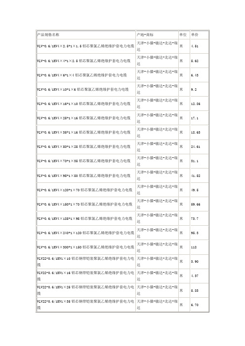
米
59.66
VLV-0.6/1KV4×185+1×95铝芯聚氯乙烯绝缘护套电力电缆
天津-小猫-敏达-北达-瑞达
米
73.7
VLV-0.6/1KV4×240+1×120铝芯聚氯乙烯绝缘护套电力电缆
天津-小猫-敏达-北达-瑞达
米
95.3
VLV-0.6/1KV4×300+1×150铝芯聚氯乙烯绝缘护套电力电缆
天津-小猫-敏达-北达-瑞达
米
17.1
VLV-0.6/1KV4×35+1×16铝芯聚氯乙烯绝缘护套电力电缆
天津-小猫-敏达-北达-瑞达
米
18.63
VLV-0.6/1KV4×50+1×25铝芯聚氯乙烯绝缘护套电力电缆
天津-小猫-敏达-北达-瑞达
米
24.61
VLV-0.6/1KV4×70+1×35铝芯聚氯乙烯绝缘护套电力电缆
天津-小猫-敏达-北达-瑞达
米
118
VLV22-0.6/1KV1×10铝芯钢带铠装聚氯乙烯绝缘护套电力电缆
天津-小猫-敏达-北达-瑞达
米
3.90
VLV22-0.6/1KV1×16铝芯钢带铠装聚氯乙烯绝缘护套电力电缆
天津-小猫-敏达-北达-瑞达
米
4.37
VLV22-0.6/1KV1×25铝芯钢带铠装聚氯乙烯绝缘护套电力电缆
天津-小猫-敏达-北达-瑞达
米
5.71
VLV22-0.6/1KV2×10铝芯钢带铠装聚氯乙烯绝缘护套电力电缆
天津-小猫-敏达-北达-瑞达
米
7.71
VLV22-0.6/1KV2×16铝芯钢带铠装聚氯乙烯绝缘护套电力电缆
PPA0155中文资料

532PDA Pigtailed Photodiode SpecificationsAbsolute Maximum RatingsAbsolute maximum limits mean that no catastrophic damage will occur if the product is subjected to these ratings for short periods, provided that each limiting parameter is in isolation and all other parameters have values within the performance specification. It should not be assumed that limiting values of more than one parameter can be applied to the product at the same time.Parameter Symbol Minimum Maximum Units Reverse Voltage Vr-20V Reverse Current Ir-1mA Forward Voltage Vf-1V Forward Current If-5mA Power Dissipation--50mW Operating Temperature Tc–40+85°C Storage Temperature Ts–40+85°C Soldering – 10 seconds--+260°C Fiber Pull--10NPerformance SpecificationsTest Conditions:Unless Otherwise Stated PDA2446 Parameter Symbol Vr = 5 V, Tc = +25°C Min.Max.Units Dark Current Id-1nATc= +85°C-50nA Reverse Breakdown Voltage Vbr Ir = 10 µA35-V Capacitance C 1 MHz- 1.7pF Responsivity Rλ = 1300 nm0.7-A/W Operating Wavelengthλ80% points12001650nM Small Signal Bandwidth Bw 1.5-GHz Linearity X1Second Order-Vr = 15 V-70dBcfl = 135 MHzf2 = 190 MHz70% Modulation0 dBm Optical PowerThird Order-As above-85dBcFiber Pigtail: Tight jacketed, self-mode stripping, singlemode fiberParameter Minimum Maximum Units Length 1.0-mCore Diameter810µmCladding Diameter122128µmConcentricity Error-8%Secondary Jacket Diameter0.8 1.0mm533PDA Mechanical Outline OptionsALL DIMENSIONS IN MILLIMETERSPDA2446-DALL DIMENSIONS IN MILLIMETERS PDA2446 Electrical Pin-OutsPIN 1: CATHODE +VEPIN 2: CASEPIN 3: ANODE –VE534Ordering InformationPDA2446-XI-XXConnector Type:AP = Angle Polished FC/PCAS = Angle Polished SC/PCUS = Ultra Polished SC/PCSF = Super Polished FC/PCFlange Type:B = BarrelD = 2 hole PCB mount, 12.7 mm between centersAdditional options are available to meet your specific needs. Please contact your local representative for details.535536537Performance Specifications Absolute Limiting RatingsAbsolute (limiting) ratings mean that no catastrophic damage will occur if the product is subjected to these ratings for short periods, provided that each limiting parameter is in isolation and all other parameters have values within the performance specification. It should not be assumed that limiting values of more than one parameter can be applied to the product at the same time.ParameterSymbol MinimumMaximumUnits Supply VoltageV DD - 5.5V Photodiode Voltage (Negative)V pin -–7V Power Dissipation--350mW Operating Temperature Tc –40+85°C Storage Temperature Ts –40+85°C Soldering – 10 seconds --+260°C Fiber Pull --10NPerformance Specifications [1]Parameter Minimum MaximumUnits Responsivity 0.75-A/W Sensitivity [2]52 Mb/s –39-dBm 155 Mb/s –36Overload [2,3]–7-dBm Bandwidth 52 Mb/s 35-MHz 155 Mb/s90Output Impedance 3060ohms V DD Supply Voltage 4.75 5.25V V DD Supply Current -50mAPhotodiode Supply–7–4.5VNotes:1. Measured over the operating temperature range and power supply tolerance.2. Measured at the data rate specified for 1 x 10⁻¹⁰ using an infinite extinction ratio laser source modulated with a 223-1PRBS pattern.3. Higher overload performance available. Contact your local Hewlett-Packard Components representative for details.Fiber Pigtail: Tight jacketed, self-mode stripping, multimodeParameter MinimumMaximumUnits Length0.4 1.2m Core Diameter 4753µm Cladding Diameter 122128µm Concentricity Error-8%Secondary Jacket Diameter0.81.0mmSchematic Diagram321. GND 2. V OUT 3. V pin 4. +V DD538Drawing DimensionsPPA0052-FC-A PPA0155-FC-AMIN.––––12.00.27M8 x 0.7513.35A B C ∅D E ∅F ∅G H DIM.MIN.2.08–––– 2.54 NOM.–∅J L M N P ∅Q ∅RDIM.ALL DIMENSIONS IN MILLIMETERSMAX.19.59.515.09.1–0.3313.55MAX.2.321.652.26.88.24.2PPA0052-SC-APPA0155-SC-AMIN.–––––12.0A B C D E FDIM.MIN.2.00.27–2.08 2.54 NOM.17.8G ∅H ∅J ∅K ∅L M DIM.ALL DIMENSIONS IN MILLIMETERSMAX.9.523.013.515.58.0–MAX.3.00.337.52.518.2PPA1052-APPA1155-AMIN.––12.0–0.27400A B C D ∅E FDIM.MIN. 2.54 NOM.––13.352.1–∅G H K L ∅M ∅NDIM.ALL DIMENSIONS IN MILLIMETERSMAX.25.019.5–9.50.331200MAX.9.52.013.552.46.25539Ordering InformationAllowable Part Numbers:PPA0052-XX -A PPA0052 - FC - A PPA0155-XX -APPA0052 - SC - A Receptacle Type:PPA1052 - A - FP FC = FC PPA1052 - A - ST SC = SCPPA1052 - A - DN PPA1052 - A - SC PPA1052-X -XX PPA1052 - D - FP PPA1155-X -XXPPA1052 - D - ST Connector Type:PPA1052 - D - DN FP = FC/PC PPA1052 - D - SC ST* = ST DN = DIN PPA0155 - FC - A SC = SCPPA0155 - SC - A PPA1155 - A - FP Flange Type:PPA1155 - A - ST A = 2 hole Panel mount, 13.4 mm between centers PPA1155 - A - DN D = 2 hole PCB mount, 12.7 mm between centersPPA1155 - A - SC PPA1155 - D - FP PPA1155 - D - ST PPA1155 - D - DN PPA1155 - D - SC*ST is a registered trademark of AT&T.PPA1052-D PPA1155-DMIN.––12.0–0.274002.54 NOM.A B C D ∅EF ∅GDIM.MIN.3.8–0.9 12.7 NOM.2.1––H J K L ∅M ∅N P DIM.ALL DIMENSIONS IN MILLIMETERSMAX.25.018.0–9.50.331200MAX.4.27.51.12.46.257.5。
(150℃) XLPE低烟无卤阻燃交联护套料应用参数

(150℃) XLPE低烟无卤阻燃交联护套料应用参数
随着现代科学技术的发展及现代生活中电力需求各个层面的增加,对线缆产品的安全性能要求,及环保提出了更高的要求。
而我国的高分子应用技术发展迅速。
低烟无卤阻燃料作为近些年出现的一个新型品种,其广泛应用与机电、地铁、高层建筑等公共场所。
原材料的质量优劣对于线缆材料的产品质量及挤出工艺有着直接影响。
由于各厂生产的低烟无卤护套料性能的差异及其所含填料与阻燃剂的种类及份量各异,因而所选用的挤制设备对护套挤出性能及产品质量的影响较大。
以下就150℃递延无卤阻燃交联护套料技术参数讲解:
150℃低烟无卤阻燃交联护套料(WDZYJH-150)技术参数
基本参数:
挤出机各区推荐设定温度:
区段1区2区3区4区机头眼模
温度(℃)170~180 185~190 190~200 190~200 200~210 200~210 备注1:推荐的螺杆压缩比为1.5~2.0。
备注2:具体温度的设定应以在一定的拉线速度情况下电线电缆的表面光滑为准。
包装、运输和储存
包装:铝塑袋内包装,牛皮纸袋外包装,每袋25kg。
外包装合格证上必须印有产品名称、型号、重量、生产批次、颜色、生产日期以及供应商名称等信息。
运输和储存:产品在运输过程中不应受日晒雨淋,其储存环境应随时保持清洁、干燥、通风。
备注:如果产品在温度≤30℃、湿度≥60%的环境下储存期超过三个月以上,建议将料在90℃~100℃温度下烘2~3小时再使用。
塑料材料测试国标大全

塑料试样状态调节和试验的标准环境(GB/T2918—1998)1.0原理:把试样暴露在规定的状态环境或温度中,那么试样与状态调节环境或温度之间即可达到可再现的温度和/或含湿量平衡的状态。
4.0状态调节a。
状态调节的周期应在材料的相关标准中规定。
当在相应标准中未规定状态调节周期时,应采用下列周期:对于标准环境23/50和27/65,不少于88小时。
对于18~28﹪的室温,不少于4小时。
5。
0试验除非另有规定,状态调节后的试样应在与状态调节相同的环境或温度下进行试验,在任何情况下,试验都应在将试样从状态调节环境内取出后立即进行。
塑料密度和相对密度试验方法(依据GB 1033——86)1.方法名称:浸渍法。
适用于各种形态的塑料制品2.定义2.1 相对密度一定体积物质的质量与同温度下等体积的参比物质之比。
参比物为水时,称为比重。
2.2 一定温度时水的密度20℅时为0.9982g/cm323℅时为0。
9976g/cm327℅时为0。
9965g/cm33.试样状态调节3.1按GB 2918—82《塑料试样状态调节和试验的标准环境》进行状态调节。
4。
试验方法:浸渍法透明塑料透光率和雾度试验方法(GB 2410—80)一,透光率:透过试样的光通量和射到试样上的光通量之比.雾度:透过试样而偏离入射方向的散射光通量与透射光通量之比。
(本方法仅把偏离入射光方向2。
5度以上的散射光通量用于计算雾度。
)陷阱:无试样和标准板的时候,能够全部吸收光。
二,试样:50*50mm. 原厚.三,光源:标准C光源。
(国际照明协会)热塑性塑料维卡软化温度(VST)的测定GB/T 1633-2000一,原理:当匀速升温时,测定标准负荷条件下标准压针刺入热塑性塑料试样表面1mm深时的温度。
二,方法:A50法:使用10N的力,加热速度为50℃/h .B50法:使用50N的力,加热速度为50℃/h 。
A120法:使用10N的力,加热速度为120℃/hB120法:使用50N的力,加热速度为120℃/h三,设备要求1,负载杆和金属架构件应具有相同的膨胀系数,部件长度的不同变化,会引起试样表观变形读数的误差.应用低膨胀系数的钢性材料(如瓦镍铁合金或硅硼玻璃)制备的试样,对每台仪器包括其使用的温度范围做空白试验进行校正,并对每个温度确定一个校正项.如果校正项为0.02mm或更大,应注意其代数符号,并通过代数方法将其加到表观针入度上,将此校正项应用于每项试验中.建议使用低膨胀合金制造的仪器。
PS21563-PP中文资料
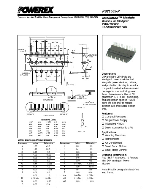
Powerex, Inc., 200 E. Hillis Street, Youngwood, Pennsylvania 15697-1800 (724) 925-7272Intellimod™ ModuleDual-In-Line Intelligent Power Module10 Amperes/600 VoltsPS21563-PDescription:DIP and Mini DIP-IPMs are intelligent power modules that integrate power devices, drivers, and protection circuitry in an ultra compact dual-in-line transfer-mold package for use in driving small three phase motors. Use of 5th generation IGBTs, DIP packaging, and application specific HVICs allow the designer to reduce inverter size and overall design time.Features:£ Compact Packages £ Single Power Supply £ Integrated HVICs£ Direct Connection to CPU Applications:£ Washing Machines £ Refrigerators £ Air Conditioners £ Small Servo Motors £ Small Motor ControlOrdering Information:PS21563-P is a 600V , 10 Ampere Mini DIP Intelligent Power Module.Note: P suffix designates lead-free lead frame.Dimensions InchesMillimeters A 1.93 49.0 B 1.20 30.5 C 0.20 5.0 D 1.82 46.23 E 0.25 6.25 F 0.32 8.0 G 0.14 3.556 H 0.04 1.0 J 0.07 1.778 K 0.02 0.5 L 0.06 1.5 M 0.07 Min. 1.8 Min. N 0.30 0.75 P0.6917.4Dimensions Inches MillimetersQ 0.02 0.5 R 0.41 10.5 S 0.05 1.2 T 0.05 1.25 U 0.10 2.5 V 0.30 7.62 W 0.16 Min. 4.0 Min. X 1.20 30.48 Y 1.61 41.0 Z 1.65 42.0 AA 0.08 Dia. 2.0 Dia. AB 0.13 Dia. 3.3 Dia. AC0.051.25Outline Drawing and Circuit DiagramPowerex, Inc., 200 E. Hillis Street, Youngwood, Pennsylvania 15697-1800 (724) 925-7272PS21563-PIntellimod™ ModuleDual-In-Line Intelligent Power Module10 Amperes/600 VoltsAbsolute Maximum Ratings, T j = 25°C unless otherwise specifiedCharacteristics Symbol PS21563-P Units Power Device Junction Temperature* T j-20 to 125 °C Module Case Operation T emperature (See T f Measurement Point Illustration) T f-20 to 100 °C Storage Temperature T stg-40 to 125 °C Mounting Torque, M3 Mounting Screws — 8.5 in-lb Module Weight (Typical) — 20 Grams Self-protection Supply Voltage Limit (Short Circuit Protection Capability)** V CC(prot.)400 Volts Isolation Voltage, AC 1 minute, 60Hz Sinusoidal, Connection Pins to Heatsink Plate V ISO2500 Volts *The maximum junction temperature rating of the power chips integrated within the DIP-IPM is 150°C (@T f≤ 100°C). However, to ensure safe operation of the DIP-IPM,the average junction temperature should be limited to T j(avg)≤ 125°C (@T f≤ 100°C).**V D = 13.5 ~ 16.5V, Inverter Part, T j = 125°C, Non-repetitive, Less than 2µsIGBT Inverter SectorCollector-Emitter Voltage V CES600 Volts Collector Current (T f = 25°C) ±I C10 Amperes Peak Collector Current (T f = 25°C, <1ms) ±I CP20 Amperes Supply Voltage (Applied between P - N) V CC450 Volts Supply Voltage, Surge (Applied between P - N) V CC(surge)500 Volts Collector Dissipation (T f = 25°C, per 1 Chip) P C20 WattsControl SectorSupply Voltage (Applied between V P1-V NC, V N1-V NC) V D20 Volts Supply Voltage (Applied between V UFB-V UFS,V VFB-V VFS, V WFB-V WFS) V DB20 Volts Input Voltage (Applied between U P, V P, W P-V NC, U N, V N, W N-V NC) V IN-0.5 ~ V D+0.5 Volts Fault Output Supply Voltage (Applied between F O-V NC) V FO-0.5 ~ V D+0.5 Volts Fault Output Current (Sink Current at F O Terminal) I FO 1 mA Current Sensing Input Voltage (Applied between C IN-V NC) V SC-0.5 ~ V D+0.5 VoltsPowerex, Inc., 200 E. Hillis Street, Youngwood, Pennsylvania 15697-1800 (724) 925-7272PS21563-PIntellimod™ ModuleDual-In-Line Intelligent Power Module10 Amperes/600 VoltsElectrical and Mechanical Characteristics, T j = 25°C unless otherwise specifiedCharacteristics Symbol Test Conditions Min. Typ. Max. UnitsIGBT Inverter SectorCollector-Emitter Cutoff Current I CES V CE = V CES, T j = 25°C — — 1.00 mAV CE = V CES, T j = 125°C — — 10 mA Diode Forward Voltage V EC T j = 25°C, -I C = 10A, V IN = 0V — 1.50 2.00 Volts Collector-Emitter Saturation Voltage V CE(sat)I C = 10A, T j = 25°C, V D = V DB = 15V, V IN = 5V — 1.60 2.10 VoltsI C = 10A, T j = 125°C, V D = V DB = 15V, V IN = 5V — 1.70 2.20 Volts Inductive Load Switching Times t on0.60 1.20 1.80 µsrr CC D DBC(on)C j INoffC(off)T f Measurement PointPowerex, Inc., 200 E. Hillis Street, Youngwood, Pennsylvania 15697-1800 (724) 925-7272PS21563-PIntellimod™ ModuleDual-In-Line Intelligent Power Module10 Amperes/600 VoltsElectrical and Mechanical Characteristics, T j = 25°C unless otherwise specifiedCharacteristics Symbol Test Conditions Min. Typ. Max. UnitsControl SectorControl Supply Voltage V D Applied between V P1-V NC, V N1-V NC13.5 15.0 16.5 VoltsV DB Applied between V UFB-V UFS, 13.0 15.0 18.5 VoltsV VFB-V VFS, V WFB-V WFSCircuit Current I D V D = V DB = 15V, V IN = 5V, — — 5.00 mATotal of V P1-V NC, V N1-V NCV D = V DB = 15V, V IN = 0V, — — 7.00 mATotal of V P1-V NC, V N1-V NCV D = V DB = 15V, V IN = 5V, — — 0.40 mAV UFB-V UFS, V VFB-V VFS, V WFB-V WFSV D = V DB = 15V, V IN = 0V, — — 0.55 mAV UFB-V UFS, V VFB-V VFS, V WFB-V WFSFault Output Voltage V FOH V SC = 0V, F O Circuit: 10k Ω to 5V Pull-up 4.9 — — VoltsV FOL V SC = 1V, I FO = 1mA — — 0.95 Volts Input Current I IN V IN = 5V 1.0 1.50 2.00 mA Short-Circuit Trip Level* V SC(ref)T j = 25°C, V D = 15V 0.43 0.48 0.53 Volts Supply Circuit Undervoltage UV DBt T rip Level, T j≤ 125°C 10.0 — 12.0 Volts Protection UV DBr Reset Level, T j≤ 125°C 10.5 — 12.5 VoltsUV Dt Trip Level, T j≤ 125°C 10.3 — 12.5 VoltsUV Dr Reset Level, T j≤ 125°C 10.8 — 13.0 Volts Fault Output Pulse Width** t FO C FO = 22nF 1.0 1.8 — msth(on)P P P NC,th(off)N N N NCThermal CharacteristicsCharacteristic Symbol Condition Min. Typ. Max. Units Junction to Fin R th(j-f)Q IGBT Part (Per 1/6 Module) — — 5.0 °C/Watt Thermal Resistance R th(j-f)D FWDi Part (Per 1/6 Module) — — 6.5 °C/WattRecommended Conditions for UseCharacteristic Symbol Condition Min. Typ. Max. Units Supply Voltage V CC Applied between P-N T erminals 0 300 400 Volts Control Supply Voltage V D Applied between V P1-V NC, V N1-V NC13.5 15.0 16.5 VoltsV DB Applied between V UFB-V UFS,13.0 15.0 18.5 VoltsV VFB-V VFS, V WFB-V WFSControl Supply VariationΔV D, ΔV DB-1 — 1 V/µs PWM Input Frequency f PWM T f ≤ 100°C, T j≤ 125°C — — 20 kHz * Short-Circuit protection is functioning only at the lower arms. Please select the value of the external shunt resistor such that the SC trip level is less than 17A.**Fault signal is asserted when the lower arm short circuit or control supply under-voltage protective functions operate. The fault output pulse-width t FO depends on the capacitance value of C FO according to the following approximate equation: C FO = (12.2 x 10⁻⁶) x t FO {F} .PS21563-PIntellimod™ ModuleDual-In-Line Intelligent Power Module 10 Amperes/600 VoltsPowerex, Inc., 200 E. Hillis Street, Youngwood, Pennsylvania 15697-1800 (724) 925-7272EMITTER CURRENT, I E , (AMPERES)R E V E R S E R E C O V E R Y T I M E , t r r , (n s )103100102101102101COLLECTOR CURRENT, I C , (AMPERES)100102101100102101COLLECTOR CURRENT, I C , (AMPERES)REVERSE RECOVERY CHARACTERISTICS(TYPICAL)FREE-WHEEL DIODEFORWARD CHARACTERISTICS(TYPICAL)C O L L E C T O R -E M I T T E R S A T U R A T I O N V O L T A G E , V C E (s a t ), (V O L T S )COLLECTOR-EMITTERSATURATION VOLTAGE CHARACTERISTICS(TYPICAL)Recommended Conditions for UseCharacteristicSymbol ConditionMin. Typ. Max. Units Allowable rms Current* I O V CC = 300V , V D = 15V , f C = 5kHz, — — 6.5 Arms PF = 0.8, Sinusoidal, T j ≤ 125°C, T f ≤ 100°CV CC = 300V , V D = 15V , f C = 15kHz, — — 4.0 ArmsPF = 0.8, Sinusoidal, T j ≤ 125°C, T f ≤ 100°CMinimum Input P WIN(on)**0.3 — — µs Pulse WidthP WIN(off)***CC D Between Rated Current 13.0 ≤ V DB ≤ 18.5V , -20°C ≤ T f ≤ 100°C, 0.5 — —µsV NC Variation V NC Between V NC -N (Including Surge) -5.0 — 5.0 Volts Arm Shoot-through t DEADFor Each Input Signal, T f < 100°C1.5——µsBlocking Time* The allowable rms current value depends on the actual application conditions.**If input signal ON pulse is less than P WIN(on), the device may not respond.***The IPM may fail to respond to an ON pulse if the preceeding OFF pulse is less than P WIN(off).Powerex, Inc., 200 E. Hillis Street, Youngwood, Pennsylvania 15697-1800 (724) 925-7272PS21563-PIntellimod™ ModuleDual-In-Line Intelligent Power Module10 Amperes/600 VoltsMini DIP-IPM Application Circuit (Shown Pins Up)Component Selection:Dsgn.T yp. Value DescriptionD11A, 600V Boot strap supply diode – Ultra fast recoveryC110-100uF, 50V Boot strap supply reservoir – Electrolytic, long life, low Impedance, 105°C (Note 5)C20.22-2.0uF, 50V Local decoupling/High frequency noise filters – Multilayer ceramic (Note 8)C310-100uF, 50V Control power supply filter – Electrolytic, long life, low Impedance, 105°CC422nF, 50V Fault lock-out timing capacitor – Multilayer ceramic (Note 4)C5100pF, 50V Optional Input signal noise filter – Multilayer ceramic (Note 1)C6200-2000uF, 450V Main DC bus filter capacitor – Electrolytic, long life, high ripple current, 105°CC70.1-0.22uF, 450V Surge voltage suppression capacitor – Polyester/Polypropylene film (Note 9)C SF1000pF, 50V Short circuit detection filter capacitor – Multilayer Ceramic (Note 6, Note 7)R SF 1.8k ohm Short circuit detection filter resistor (Note 6, Note 7)R SHUNT5-100 mohm Current sensing resistor - Non-inductive, temperature stable, tight tolerance (Note 10)R110 ohm Boot strap supply inrush limiting resistor (Note 5)R2330 ohm Optional control input pull-up resistor (Note 1, Note 2)R310k ohm Fault output signal pull-up resistor (Note 3)Notes:1) To prevent input signal oscillations minimize wiring length to controller (∼2cm). Additional RC filtering (C5 etc.) may be required.If filtering is added be careful to maintain proper dead time and voltage levels. See application notes for details.2) Internal HVIC provides high voltage level shifting allowing direct connection of all six driving signals to the controller.3) F O output is an open collector type. Pull-up resistor (R3) should be adjusted to current sink capability of the module.4) C4 sets the fault output duration and lock-out time. C4 ≈ 12.2E-6 x t FO, 22nF gives ∼1.8ms5) Boot strap supply component values must be adjusted depending on the PWM frequency and technique.6) Wiring length associated with R SHUNT, R SF, C SF must be minimized to avoid improper operation of the SC function.7) R SF, C SF set short circuit protection trip time. Recommend time constant is 1.5us-2.0us. See application notes.8) Local decoupling/high frequency filter capacitors must be connected as close as possible to the modules pins.9) The length of the DC link wiring between C6, C7, the DIP’s P terminal and the shunt must be minimized to prevent excessive transient voltages.In particular C7 should be mounted as close to the DIP as possible.10) Use high quality, tight tolorance current sensing resistor. Connect resistor as close as possible to the DIP’s N terminal.Be careful to check for proper power rating. See application notes for calculation of resistance value.。
PP附着力处理剂JC-150使用说明书

PP附着力处理剂JC-150使用说明书
(内容由静川化工整理发布)
PP附着力处理剂是喷涂或者是涂装型的底涂附着力促进剂,可提高油漆及胶粘剂在PP及改性PP材质表面的附着力。
在PP底材上喷涂或者涂刷PP附着力处理剂JC-150可有效解决材质与油漆附着力差导致的掉漆或者脱胶等问题。
使用特点:
1.适用于PP材料表面喷涂及胶粘工艺
2.优异的提升PP表面附着力性能
3.适用油漆体系广泛,对水性聚氨酯等胶粘剂也适用
4.对PP及改性PP等材质通用性强
5.易于操作,只需喷涂或涂刷于PP材质表面
使用方法:
通过溶剂开稀好之后,喷涂或涂刷于PP材质表面,相当于底涂的形式,烘干或自干之后再喷涂油漆或涂刷胶粘剂(例如:普通漆、橡胶漆、PU漆、UV漆、水性聚氨酯胶粘剂、水性植绒胶水等),在上线使用之前,先通过免费样品进行测试。
注意事项:
1.在使用中应对材质表面进行清洁清理
2.根据材质及工艺的情况,可以适当提高开稀浓度
3.一般喷涂3-5μm即可
4.有烘烤条件的建议70℃烘烤5分钟,没有条件的可在施工之后自干15分钟之后再喷漆。
- 1、下载文档前请自行甄别文档内容的完整性,平台不提供额外的编辑、内容补充、找答案等附加服务。
- 2、"仅部分预览"的文档,不可在线预览部分如存在完整性等问题,可反馈申请退款(可完整预览的文档不适用该条件!)。
- 3、如文档侵犯您的权益,请联系客服反馈,我们会尽快为您处理(人工客服工作时间:9:00-18:30)。
DC output voltage 13.5V Output V.tolerance ±2%Output rated current 11.2A Output current range 0-11.5A Ripple & noise 100mV Line regulation ±0.5%Load regulation ±1% DC output power 151.2W Efficiency
80%
DC voltage adj.
+10, -5%
Input voltage range 2.2A/115V, 1.1A/230V; 3.3V: 1.5A/115V, 0.8A/230V Inrush current cold start 40A//230V Leakage current <3.5mA/240VAC Overload protection 105%~150%
type: continuous current limiting, auto recovery Over voltage protection 110%~135%
type: shutdown, RE power on Over temp. protection ---
Temperature coefficient ±0.05% / °C (0~50°C)Set up, rise, hold up time 600ms, 30ms, 20ms
Power factor PF>0.96/230VAC, PF>0.98/115VAC
Vibration
10~500Hz, 2G 10min./1cycle (1 hour each axes)
Withstand voltage I/P-O/P: 3KVAC, I/P-FG: 1.5KVAC, O/P-FG: 0.5KVAC, for 1 min.Isolation resistance
I/P-O/P, I/P-FG, O/P-FG: 500VDC / 100M Ohms min.
Working temp., humidity -10°C~+60% (refer to output derating curve), 20%-90% RH Storage temp., humidity -20ºC~+85ºC, 10%~95% RH
Dimensions 8.74x2.95x1.61 inches (222x75x41mm) Weight
1.37lbs (0.62Kgs)
Safety standards UL1950, TUV EN60950
EMC standards
CISPR22 (EN55022) CLASS B, EN61000-4-2,3,4,5,6,8,11; ENV50204, EN61000-3-2,-3
Notes:
1. All parameters are specified at 230VAC input, rated load, 25°C 70% RH ambient
2. Tolerance includes set up tolerance, line regulation, load regulation
3. Ripple & noise are measured at 20MHz by using a 12” twisted pair terminated with a 0.1uF & 47 uF capacitor
4. Line regulation is measured from low line to high line at rated load
*V-Infinity reserves the right to make changes to its products or to discontinue any product or service without notice, and to advise cus-tomers to verify the most up-to-date product information before placing orders. V-Infinity assumes no liability or responsibility for cus-tomer’s applications using V-Infinity products other than repair or replacing (at V-I’s option) V-Infinity products not meeting V-I’s pub-lished specifications. Nothing will be covered outside of standard product warranty.
Features
·Universal AC input / Full range
·Built-in active PFC function, PF>0.96
·Protections:Short circuit/Over load/Over voltage ·Protections:Over temperature(option)·Cooling by free air convection ·100% full load burn-in test
·Fixed switching frequency at PFC:67KHz ·PWM:134KHz
·3 year warranty
Dimensions (mm)。
