FYS-12011AX-1中文资料
P4311-FU120中文资料

60PPR 96PPR 150PPR 180PPR 200PPR 240PPR 250PPR 256PPR 270PPR 300PPR 360PPR 480PPR 500PPR 512PPR
120PPR 192PPR 300PPR 360PPR 400PPR 480PPR 500PPR 512PPR 540PPR 600PPR 720PPR 960PPR 1000PPR 1024PPR
0600
Encoders to be shipped with the PPR as ordered & quadrature channel type with 50/50 duty cycle pulse. *Quadrature available for 1st three SW 1 & 2 columns (below).
H e r c u l e s
6000 Series
4000 Series
For the latest specifications visit our website
元器件交易网
Hercules Encoders “Value Added” Programmable Encoder
元器件交易网
Hercules Encoders
Programmable
Incremental Encoders
Select PPR’s Choice of 5 PPR’s Select Pulse Width 10µSecs, 30µSecs or Square Wave Select Channels •Single or quadrature channels •Count with up/down direction •Up count channel and down count channel Function Selection Switches SW1 SW2 SW3 SW4 SW5 on bottom
(完整word版)S120样本完整版

310
14
6SL3000-2BE33-2AA0
HSL220-S310
200
160
6SL3310-1TE33-8AA0
380
508
0.042
6SL3000-0CE35-1AA0
HSL119-S508
380
11
6SL3000-2BE33-8AA0
HSL220-S380
250
200
6SL3310-1TE35-0AA0
63
60
71
0.259
6SL3203-0CD25-3AA0
HSL119-S71
37
30
6SL3210-1SE27-5UA0
78
75
105
0.175
6SL3203-0CJ28-6AA0
HSL119-S105
90
47
6SE6400-3TC08-0ED0
HSL220-S90
45
37
6SL3210-1SE31-0UA0
3.1
3.1
1.5
6SL3210-1SE14-1UA0
4.1
4.1
4.8
3.828
6SE6400-3CC00-6AD3
HSL119-S4.8
2.2
6SL3210-1SE16-0UA0
5.6
5.9
9
2.042
6SL3203-0CD21-0AA0
HSL119-S9
10
424
6SL3202-0AE21-0CA0
490
490
9
6SL3000-2BE35-0AA0
HSL220-S490
蒂森电梯

诊断仪I操作说明- 功能 -MA136510046I 型诊断仪7 段数字显示屏起动/停止按键(闪烁1)旋转脉冲LK 传感器运行:IS/RS2IS 上行SR 模块反馈IS 下行程序选择旋钮安全回路EK LN 传感器HKTK W/W1 接触器KT WO/WU 接触器当I 型诊断仪没有进入 15AF 功能时,LK 和 LN 感应器被井道码板遮挡时,诊断仪上的 LK 和LN 相应的发光二极管闪烁。
当 I 型诊断仪进入 15AF 功能时,LK 和 LN 感应器被井道码板遮挡时,诊断仪上的LK和LN相应的发光二极管不闪烁,并且在功能15AF里这两个LED的配位也互相对换(见MA13,类型6510,顺序号046)。
用诊断仪I总共可查询或处理16项功能。
用户可以通过程序选择旋钮选定各项功能。
选定的功能出现在七段数字显示屏上(闪烁显示)。
使用方法将诊断仪I插入相关的印刷电路板(CPU,门控制,LMS1等等)。
显示屏显示某项功能(闪烁)。
用户可调节程序选择旋钮,选择需要的功能。
只有在显示屏闪烁的情况下,才能从一个功能转换到另一个功能。
退出选定功能:将程序选择旋钮旋转一档,然后按启动/停止键>2秒。
用户可通过AF00(dF00,bF00)或者将主开关切断再接通,退出教入功能。
本书中对诊断仪I的阐述或功能描述适用于04.86.3版起的所有工作程序。
TCI/TCM 电梯控制系统的现行工作程序将在紧急信息栏中公布。
诊断仪I的所有功能将在以下章节中分别作详细介绍。
1)当七段显示屏闪烁时,上图侧面所示功能将由A列及B列发光二极管指示出来。
2)IS ...检修运行RS ...应急电动运行。
诊断仪I(适用于电梯控制系统TCI和TCM)当TCI采用04.86/3版起的工作程序,TCM采用MC,MC1,MC2,MC3控制系统时,以下功能可供选择。
功能界面功能名称描述页数01 00故障堆栈读出故障堆栈及事件堆栈F01 1-3402 00显示订单号06.88/6 版起的工作程序可实现此功能F02 103 00显示轿厢位置轿厢位置显示在7段显示器上;LED无意义F03 104 00运行阶段显示屏和LED显示当前的运行阶段F04 1-205 00存储器地址 A 列及 B 列 LED 显示重要的存储器地址(轿厢)F05 1-2006 00门锁装置(TCI)主门:A列及B列LED显示F06 LMS2(TCM)LMS2 教入107 00门锁装置(TCI)后门:A列及B列LED显示F07 CPI 参数(TCM)显示CPI控制器参数(仅限TCM)1-308 00轿厢召唤对主门一侧楼层发轿厢召唤F08109 00厅门召唤发下行召唤(TU) -主门侧F09 110 00厅门召唤发上行召唤(TU) -主门侧F10 111 00轿厢召唤对后门一侧楼层发轿厢召唤F11112 00厅门召唤发下行召唤(TU) -后门侧F12 113 00厅门召唤发上行召唤(TU) -后门侧F13 114 00显示版本及标志位显示CPU工作程序版本及发行日期。
AN1201SM中文资料
■ Applications
• Cellular phones
■ Package
• SMINI-5DA
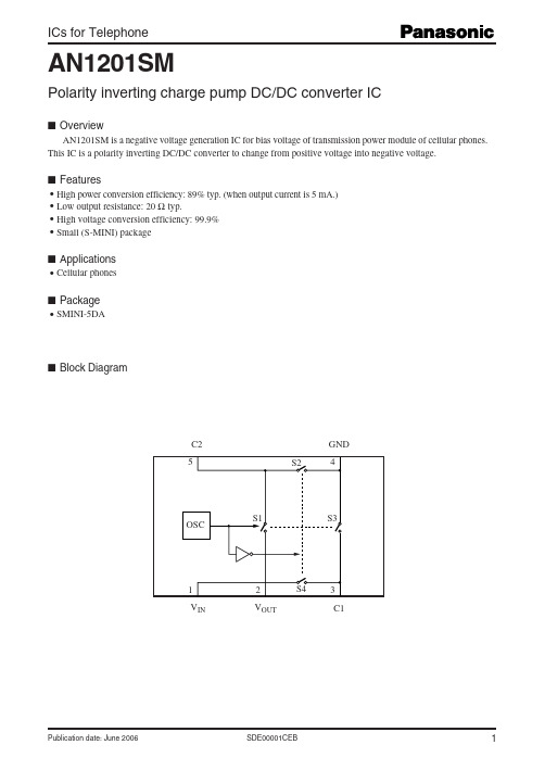
■ Block Diagram
C2 5 S2
GND 4
OSC
S1
S3
1 VIN
2 VOUT
S4
3 C1
Publication date: June 2006
SDE00001CEB
1
AN1201SM
ICs for Telephone
AN1201SM
Polarity inverting charge pump DC/DC converter IC
■ Overview
AN1201SM is a negative voltage generation IC for bias voltage of transmission power module of cellular phones. This IC is a polarity inverting DC/DC converter to change from positive voltage into negative voltage.
Request for your special attention and precautions in using the technical information and semiconductors described in this book
(1) If any of the products or technical information described in this book is to be exported or provided to non-residents, the laws and regulations of the exporting country, especially, those with regard to security export control, must be observed. (2) The technical information described in this book is intended only to show the main characteristics and application circuit examples of the products, and no license is granted under any intellectual property right or other right owned by our company or any other company. Therefore, no responsibility is assumed by our company as to the infringement upon any such right owned by any other company which may arise as a result of the use of technical information described in this book. (3) The products described in this book are intended to be used for standard applications or general electronic equipment (such as office equipment, communications equipment, measuring instruments and household appliances). Consult our sales staff in advance for information on the following applications: – Special applications (such as for airplanes, aerospace, automobiles, traffic control equipment, combustion equipment, life support systems and safety devices) in which exceptional quality and reliability are required, or if the failure or malfunction of the products may directly jeopardize life or harm the human body. – Any applications other than the standard applications intended. (4) The products and product specifications described in this book are subject to change without notice for modification and/or improvement. At the final stage of your design, purchasing, or use of the products, therefore, ask for the most up-to-date Product Standards in advance to make sure that the latest specifications satisfy your requirements. (5) When designing your equipment, comply with the range of absolute maximum rating and the guaranteed operating conditions (operating power supply voltage and operating environment etc.). Especially, please be careful not to exceed the range of absolute maximum rating on the transient state, such as power-on, power-off and mode-switching. Otherwise, we will not be liable for any defect which may arise later in your equipment. Even when the products are used within the guaranteed values, take into the consideration of incidence of break down and failure mode, possible to occur to semiconductor products. Measures on the systems such as redundant design, arresting the spread of fire or preventing glitch are recommended in order to prevent physical injury, fire, social damages, for example, by using the products. (6) Comply with the instructions for use in order to prevent breakdown and characteristics change due to external factors (ESD, EOS, thermal stress and mechanical stress) at the time of handling, mounting or at customer's process. When using products for which damp-proof packing is required, satisfy the conditions, such as shelf life and the elapsed time since first opening the packages. (7) This book may be not reprinted or reproduced whether wholly or partially, without the prior written permission of Matsushita Electric Industrial Co., Ltd.
电感式传感器 BI2-EM12-Y1X-H1141说明书

T 07:17:00+02:00型号BI2-EM12-Y1X-H1141货号4010201额定工作距离Sn 2 mm 安装方式齐平实际测量范围ð (0,81 x Sn) mm修正系数37#钢 = 1; 铝 = 0.3; 不锈钢= 0.7; 黄铜 = 0.4重复精度ð 2 满量程的 %温度漂移10 %磁滞1…10 %环境温度-25…+70 °C 输出性能2线, NAMUR 开关频率 5 kHz电压Nom. 8.2 VDC 无激励电流损耗ï 2.1 mA 激励电流损耗ð 1.2 mA认证依据KEMA 02 ATEX 1090X 内置 电感(L ) / 电容 (C )150 nF / 150 µH防爆标志防爆标识为II 1 G/Ex ia IIC T6/II 1 D Ex ia D 20 T115°C Da(最大 U = 20 V, I = 20 mA, P = 200 mW)设计圆柱螺纹, M12 x 1尺寸52 mm外壳材料不锈钢型, V2A (1.4301)感应面材料塑料, PA 最大扭矩10 Nm连接接插件, M12 x 1防震动性55 Hz (1 mm)防冲击性30 g (11 ms)防护等级IP67MTTF 6198 years 符合SN 29500 (Ed.99) 40 °C认证开关状态指示LED指示灯 黄sATEX 防爆认证II 组设备,设备等级1G. 可用于气体危险0区sATEX 防爆认证II组设备,设备等级1D,可应用于粉尘危险2区s 满足SIL2和IEC61508标准s M12 x 1圆柱螺纹s 不锈钢1.4301s 2线直流, nom. 8.2 VDCs输出遵循本安型DIN EN 60947-5-6(NAMUR)标准sM12 x 1接插件接线图功能原理电感式传感器以非接触和无磨损的方式检测金属物体。
DC1-S2011NB-A20N变频驱动器说明书

Hz
0 - 50/60 (max. 120)
kHz
16
adjustable 4 - 32 (audible)
U/f control Speed control with slip compensation
Hz
0.1
A
10.5
Rated operational current at an operating frequency of 16 kHz and an ambient air temperature of +50 °C
1, parameterizable, 0 - 10 V
Eaton 169518 ED2018 V42.0 EN
2/7
Digital inputs Digital outputs Relay outputs Interface/field bus (built-in)
Assigned switching and protective elements
FAZ-B25/1N
A
25
DX-LN1-024
DX-BR3-100
Design verification as per IEC/EN 61439
Technical data for design verification
Rated operational current for specified heat dissipation
Mains voltage (50/60Hz) Input current (150% overload) System configuration Supply frequency Frequency range Mains switch-on frequency Power section Function Overload current (150% overload) max. starting current (High Overload) Note about max. starting current Output voltage with Ve
XFS-1风速仪说明书

XFS-1风速风向仪使用说明书目录1、产品简介 (2)2、功能特点 (2)3、技术参数 (2)4、安装使用方法 (3)5、菜单操作说明 (4)6、产品成套性 (4)7、异常现象的分析及解决方法 (5)8、注意事项 (5)9、安装方法 (6)10、附表:风力(风速)等级表 (6)1、产品简介XFS-1型风速风向仪是用于测量并记录大气中风速与风向的气象仪器。
本仪器采用高清液晶显示屏显示当前日期时间及风速、风向值;内置大容量FLASH 存储芯片可自动存储至少一年的气象数据;仪器配备有三种通讯接口(RS232/RS485/USB)用于与计算机建立通讯连接,通过配套的上位机软件可远程观测实时风速风向,用户还可利用该功能完善的气象软件对气象数据作进一步的处理分析。
本仪器可广泛用于气象、农林、环保、海洋、机场、港口、科学考察等领域。
2、功能特点●高清字符型液晶显示屏,人机界面友好;●风速、风向测量精度高,系统稳定可靠;●大容量数据存储,最多可存储57344条气象数据(数据记录间隔可在1-240分钟之间设置);●通讯接口人性化设计,三种通讯接口可根据需要任意选择;●功能强大的上位机软件,方便远程监测及气象数据的处理分析;●结构设计科学合理,安装方便;3、技术参数供电:□AC 220V;□DC 24V;□DC 12V ;□DC 5V ;量程:风速:0~45m/s 风向:0~360°;准确度:风速:±(0.3+0.03V)m/s 风向:±3°;启动风速:≤0.8m/s长期稳定性:风速:<0.1m/s/y 风向:0°/y内部存储:4M bit(57344条气象数据);记录间隔:1分钟~240分钟连续可调;通讯方式:RS232,RS485,USB,GPRS主机工作环境:-40℃~50℃;5%RH~95%RH;产品尺寸:165 mm×125 mm×75mm4、安装使用方法确认125.00 m m165.00 mm详细接口说明:3芯航插风向传感器接口5芯航插风速传感器接口RS232232通讯接口USBUSB 通讯接口RS485485通讯接口3个端子从左至右分别为:GND 、485+、485-液晶显示屏按键面板风速传感器接口 风向传感器接口RS232接口 RS485接口 USB 接口 电源线接口5、菜单操作说明(1)按键功能介绍(2)菜单操作流程6、产品成套性(1)PH-SD1风速风向仪(采集仪):1套(2)风速、风向传感器:1套(3)通讯线:1根(4)电源适配器:2个(PH风速风向仪:12V/1A;GPRS模块:12V/1.5A(选配))(5)软件光盘:1套7、异常现象的分析及解决方法注:若不符合以上说明,或说明无法使机器恢复正常,请及时联系我公司售后服务部门或业务人员,以便维修或更换。
mpas112a继电器参数

mpas112a继电器参数MPAS112A继电器是一种常用的电控产品,具有多种功能和特性。
下面将详细介绍MPAS112A继电器的参数及其相关信息。
1.功能:MPAS112A继电器主要用于控制和分离高电压和高电流的电气信号。
它是一种可编程的电气装置,可以根据不同的输入信号进行开关操作。
它可以实现电路的闭合和断开,从而控制其他电气设备的工作状态。
2.参数:-输入电压:通常为12V,适用于大多数低电压系统。
-额定负载电流:通常为10A,具有很好的负载容量。
-功率:额定功率为120W。
-继电器类型:MPAS112A继电器属于通用型继电器,广泛应用于各种电器设备中。
-绝缘电阻:通常大于100MΩ,具有较好的绝缘性能。
-工作温度范围:通常为-40℃至+85℃,适应各种工作环境。
-尺寸:MPAS112A继电器的产品尺寸通常为18mm x 15.7mm x15mm,体积较小。
3.特点:-高可靠性:MPAS112A继电器采用优质材料制造,具有较长的使用寿命和高可靠性。
-高灵敏度:MPAS112A继电器具有快速响应的特点,可以迅速实现信号的传输和电路的开关。
-低功耗:MPAS112A继电器在工作状态下耗电量较低,节约能源。
-安装方便:MPAS112A继电器采用插针式结构,便于安装和更换。
-应用广泛:MPAS112A继电器可广泛应用于电力系统、通信设备、工业自动化等领域。
4.应用领域:-汽车电子:MPAS112A继电器可以用于汽车电路中的启动、照明和信号控制等方面。
-家电产品:MPAS112A继电器可用于空调、电视、电冰箱等家电设备的控制电路中。
-通信设备:MPAS112A继电器可以用于光纤通信、网络设备等领域中的信号传输和开关控制。
-工业控制:MPAS112A继电器在工业自动化生产线、机器控制等方面具有重要作用。
-家居安全:MPAS112A继电器可以用于家庭安防系统的报警、监控等控制任务。
总结:MPAS112A继电器是一种功能强大、使用广泛的电气控制设备。
一产品的技术参数

一产品的技术参数实测技术参数
一、型号:120HFL
单元特性:
最大额定功率:120千瓦
最大电流:250A
控制器输入电压范围:200-480V
控制器输出电压范围:0-600V
峰值功率因数:0.95
额定制动功率因数:0.9
机械特性:
外形尺寸:340mm*210mm*180mm
重量:8.3kg
额定旋转转速:3000r/min
额定旋转速度范围:50-3000 r/min
最大旋转速度:30Hz
最大转矩:8.8Nm
安全保护:
过流保护:超过250A自动断开
过温保护:超过120度自动断开
过压保护:超过600V自动断开
低压保护:低于200V自动断开
控制特性:
PID响应时间:2s
控制方式:位置控制,矢量控制
电子时间常数:2ms
运行模式:自动,手动,程序
程序操作:支持操作系统
I/O端口:
输入:4个数字量输入端口
输出:6个数字量输出端口
通信端口:
以太网端口
CAN总线
电缆接口:
主电缆接口:液体,油,气,消防
控制电缆接口:液体,油,气,消防应用部件:
液压泵:2个
风扇:2个
传感器:2个
过滤器:2个
消毒机:1个
其他特性:
抗振能力:抗4-5级地震振动
抗湿能力:抗湿度≤90%
超声波侦测:支持
电子锁:支持。
Y系列电机样本

西安西玛电机(集团)股份有限公司
Tel:029-86171136
XI'AN SIMO MOTOR,INC(GROUP)
Fax:029-86171116
Email:571057738@
转速
r/min
2830 2830 2840 2840 2890 2890 2900 2900 2930 2930 2930 2940 2950 2950 2970 2970 2970 2970 2980 2980 2980 2980 2980 2985 2985 2985
Y315S-10 45 Y315M-10 55 Y315L2-10 75 Y355M1-10 90 Y355M2-10 110 Y355L1-10 132
西 安 西玛 电 机(集 团)股 份 有限 公 司
额定 电流
A 206 246 300 347 375 311 466
5.8 7.7 9.9 13.3 17.7 24.8 34.1 41.3 47.6 63 78.2 93.2 114 152 179 218 264 319 368 398
106 108 108 108
56 65 56 65 62 67 62 67 66 71 66 71 66 71 69 75 70 75 70 78 73 78 73 78 76 81 76 81 79 84 79 84 87 92 87 92
振动 速度 mm/s 1.8 1.8 1.8 1.8 1.8 1.8 1.8 2.8 2.8 2.8 2.8 2.8 2.8 2.8 4.5 4.5 4.5 4.5
0.55 0.75 1.1 1.5 2.2
3 4 5.5 7.5
英飞凌 DF4-19MR20W3M1HF_B11 EasyPACK 模块 数据表
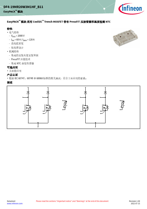
EasyPACK ™ 模块 采用 CoolSiC ™ Trench MOSFET 带有PressFIT 压接管脚和温度检测NTC 特性•电气特性-V DSS = 2000 V-I DN = 60 A / I DRM = 120 A -高电流密度-低电感设计•机械特性-集成的安装夹使安装坚固-PressFIT 压接技术-集成NTC 温度传感器可选应用•太阳能应用产品认证•根据 IEC 60747、60749 和 60068 标准的相关测试,符合工业应用的要求。
描述DF4-19MR20W3M1HF_B11EasyPACK ™ 模块内容描述 . . . . . . . . . . . . . . . . . . . . . . . . . . . . . . . . . . . . . . . . . . . . . . . . . . . . . . . . . . . . . . . . . . . . . . . . . . . . . . . . . . . . . . . . .1特性 . . . . . . . . . . . . . . . . . . . . . . . . . . . . . . . . . . . . . . . . . . . . . . . . . . . . . . . . . . . . . . . . . . . . . . . . . . . . . . . . . . . . . . . . .1可选应用 . . . . . . . . . . . . . . . . . . . . . . . . . . . . . . . . . . . . . . . . . . . . . . . . . . . . . . . . . . . . . . . . . . . . . . . . . . . . . . . . . . . .1产品认证 . . . . . . . . . . . . . . . . . . . . . . . . . . . . . . . . . . . . . . . . . . . . . . . . . . . . . . . . . . . . . . . . . . . . . . . . . . . . . . . . . . . .1内容 . . . . . . . . . . . . . . . . . . . . . . . . . . . . . . . . . . . . . . . . . . . . . . . . . . . . . . . . . . . . . . . . . . . . . . . . . . . . . . . . . . . . . . . . .2 1封装 . . . . . . . . . . . . . . . . . . . . . . . . . . . . . . . . . . . . . . . . . . . . . . . . . . . . . . . . . . . . . . . . . . . . . . . . . . . . . . . . . . . . . . . . .3 2MOSFET . . . . . . . . . . . . . . . . . . . . . . . . . . . . . . . . . . . . . . . . . . . . . . . . . . . . . . . . . . . . . . . . . . . . . . . . . . . . . . . . . . . . .3 3Body diode . . . . . . . . . . . . . . . . . . . . . . . . . . . . . . . . . . . . . . . . . . . . . . . . . . . . . . . . . . . . . . . . . . . . . . . . . . . . . . . . . .5 4Diode, 轉換器 . . . . . . . . . . . . . . . . . . . . . . . . . . . . . . . . . . . . . . . . . . . . . . . . . . . . . . . . . . . . . . . . . . . . . . . . . . . . . . . .5 5负温度系数热敏电阻 . . . . . . . . . . . . . . . . . . . . . . . . . . . . . . . . . . . . . . . . . . . . . . . . . . . . . . . . . . . . . . . . . . . . . . . . .6 6特征参数图表 . . . . . . . . . . . . . . . . . . . . . . . . . . . . . . . . . . . . . . . . . . . . . . . . . . . . . . . . . . . . . . . . . . . . . . . . . . . . . . . .7 7电路拓扑图 . . . . . . . . . . . . . . . . . . . . . . . . . . . . . . . . . . . . . . . . . . . . . . . . . . . . . . . . . . . . . . . . . . . . . . . . . . . . . . . . .11 8封装尺寸 . . . . . . . . . . . . . . . . . . . . . . . . . . . . . . . . . . . . . . . . . . . . . . . . . . . . . . . . . . . . . . . . . . . . . . . . . . . . . . . . . . .11 9模块标签代码 . . . . . . . . . . . . . . . . . . . . . . . . . . . . . . . . . . . . . . . . . . . . . . . . . . . . . . . . . . . . . . . . . . . . . . . . . . . . . . .12修订历史 . . . . . . . . . . . . . . . . . . . . . . . . . . . . . . . . . . . . . . . . . . . . . . . . . . . . . . . . . . . . . . . . . . . . . . . . . . . . . . . . . . .13免责声明 . . . . . . . . . . . . . . . . . . . . . . . . . . . . . . . . . . . . . . . . . . . . . . . . . . . . . . . . . . . . . . . . . . . . . . . . . . . . . . . . . . .141封装表 1绝缘参数特征参数代号标注或测试条件数值单位绝缘测试电压V ISOL RMS, f = 50 Hz, t = 1 min 3.2kV 内部绝缘基本绝缘 (class 1, IEC 61140)Al2O3爬电距离d Creep端子至散热器10.4mm 爬电距离d Creep端子至端子10.2mm 电气间隙d Clear端子至散热器10.1mm 电气间隙d Clear端子至端子9.4mm 相对电痕指数CTI > 400相对温度指数 (电)RTI封装140°C 表 2特征值特征参数代号标注或测试条件数值单位最小值典型值最大值杂散电感,模块L sCE14nH 储存温度T stg-40125°CM5, 螺丝 1.3 1.5Nm 模块安装的安装扭距M根据相应的应用手册进行安装重量G78g 注:The current under continuous operation is limited to 25 A rms per connector pin.2MOSFET表 3最大标定值特征参数代号标注或测试条件数值单位漏源极电压V DSS T vj = 25 °C2000V 植入漏极电流I DN60A 连续漏极直流电流I DDC T vj = 175 °C, V GS = 18 V T H = 65 °C50A 漏极重复峰值电流I DRM verified by design, t p limited by T vjmax120A 柵-源瞬态最大电压V GS D < 0.01-10/23V 柵-源稳态最大电压V GS-7/20V表 4推荐值特征参数代号标注或测试条件[ZH]Values单位通态栅极电压V GS(on)18V 断态栅极电压V GS(off)-3V表 5特征值特征参数代号标注或测试条件数值单位最小值典型值最大值漏源通态电阻R DS(on)I D = 60 A V GS = 18 V,T vj = 25 °C17.226.5mΩV GS = 18 V,T vj = 125 °C36.6V GS = 18 V,T vj = 175 °C51.7栅极阈值电压V GS(th)I D = 34 mA, V DS = V GS, T vj = 25 °C, (tested after1ms pulse at V GS = +20 V)3.454.35.15V 栅极电荷Q G V DD = 1200 V, V GS = -3/18 V0.234µC 内部栅极电阻R Gint T vj = 25 °C 3.8Ω输入电容C ISS f = 100 kHz, V DS = 1200 V,V GS = 0 VT vj = 25 °C7.24nF输出电容C OSS f = 100 kHz, V DS = 1200 V,V GS = 0 VT vj = 25 °C0.169nF反向传输电容C rss f = 100 kHz, V DS = 1200 V,V GS = 0 VT vj = 25 °C0.012nF C OSS存储能量E OSS V DS = 1200 V, V GS = -3/18 V, T vj = 25 °C154µJ 漏源泄漏电流I DSS V DS = 2000 V, V GS = -3 V T vj = 25 °C0.012205µA 栅极漏电流I GSS V DS = 0 V, T vj = 25 °C V GS = 20 V400nA开通延迟时间(感性负载)t d on I D = 60 A, R Gon = 1.6 Ω,V DD = 1200 V,V GS = -3/18 V T vj = 25 °C38.1ns T vj = 125 °C38.1T vj = 175 °C38.1上升时间(感性负载)t r I D = 60 A, R Gon = 1.6 Ω,V DD = 1200 V,V GS = -3/18 V T vj = 25 °C26ns T vj = 125 °C26T vj = 175 °C26关断延迟时间(感性负载)t d off I D = 60 A, R Goff = 2 Ω,V DD = 1200 V,V GS = -3/18 V T vj = 25 °C74.4ns T vj = 125 °C81.5T vj = 175 °C83.9(待续)表 5(续) 特征值特征参数代号标注或测试条件数值单位最小值典型值最大值下降时间(感性负载)t f I D = 60 A, R Goff = 2 Ω,V DD = 1200 V,V GS = -3/18 V T vj = 25 °C16ns T vj = 125 °C16.1T vj = 175 °C17.1开通损耗能量 (每脉冲)E on I D = 60 A, V DD = 1200 V,Lσ = 35 nH, V GS = -3/18 V,R Gon = 1.6 Ω, di/dt = 5kA/µs (T vj = 175 °C)T vj = 25 °C 1.5mJ T vj = 125 °C 1.5T vj = 175 °C 1.5关断损耗能量 (每脉冲)E off I D = 60 A, V DD = 1200 V,Lσ = 35 nH, V GS = -3/18 V,R Goff = 2 Ω, dv/dt = 56.14kV/µs (T vj = 175 °C)T vj = 25 °C0.435mJ T vj = 125 °C0.481T vj = 175 °C0.529结-散热器热阻R thJH每个MOSFET0.515K/W 允许开关的温度范围T vj op-40175°C注:The body diode of CoolSiC™ Trench MOSFET cannot be used for polarity protection. An external diode is needed for this purpose.The selection of positive and negative gate-source voltages impacts the long-term behavior of the MOSFETand body diode. The design guidelines described in Application Notes AN 2018-09 and AN 2021-13 must beconsidered to ensure sound operation of the device over the planned lifetime.T vj op > 150°C is allowed for operation at overload conditions for MOSFET and body diode. For detailedspecifications, please refer to AN 2021-133Body diode表 6特征值特征参数代号标注或测试条件数值单位最小值典型值最大值正向电压V SD I SD = 60 A, V GS = -3 V T vj = 25 °C 4.6 6.15VT vj = 125 °C 4.15T vj = 175 °C44Diode, 轉換器表 7最大标定值特征参数代号标注或测试条件数值单位反向重复峰值电压V RRM T vj = 25 °C2000V (待续)5 负温度系数热敏电阻表 7(续) 最大标定值特征参数代号标注或测试条件数值单位连续正向直流电流I F40A 正向重复峰值电流I FRM t P = 1 ms80A I2t-值I2t t P = 10 ms, V R = 0 V T vj = 125 °C90A²sT vj = 175 °C70表 8特征值特征参数代号标注或测试条件数值单位最小值典型值最大值正向电压V F I F = 40 A T vj = 25 °C 1.50 1.85VT vj = 125 °C 2.17T vj = 175 °C 2.67结-散热器热阻R thJH每个二极管0.685K/W 允许开关的温度范围T vj op-40175°C注:T vj op > 150°C is allowed for operation at overload conditions for booster diode. For detailed specifications, please refer to AN 2021-135负温度系数热敏电阻表 9特征值特征参数代号标注或测试条件数值单位最小值典型值最大值额定电阻值R25T NTC = 25 °C5kΩR100偏差ΔR/R T NTC = 100 °C, R100 = 493 Ω-55%耗散功率P25T NTC = 25 °C20mW B-值B25/50R2 = R25 exp[B25/50(1/T2-1/(298,15 K))]3375K B-值B25/80R2 = R25 exp[B25/80(1/T2-1/(298,15 K))]3411K B-值B25/100R2 = R25 exp[B25/100(1/T2-1/(298,15 K))]3433K 注:根据应用手册标定7电路拓扑图图 18封装尺寸图 29模块标签代码图 3修订历史修订历史修订版本发布日期变更说明0.102022-07-05Initial version1.002022-07-15Final datasheetTrademarksAll referenced product or service names and trademarks are the property of their respective owners.Edition 2022-07-15Published byInfineon Technologies AG 81726 Munich, Germany© 2022 Infineon Technologies AG All Rights Reserved.Do you have a question about any aspect of this document? Email: ********************Document referenceIFX-ABE754-002重要提示本文档所提供的任何信息绝不应当被视为针对任何条件或者品质而做出的保证(质量保证)。
GRCX120-3 电子调节阀数据表说明书
GRCX120-3FootnotesOn/Off, Floating point, Non fail-safe, 100...240 VTechnical dataElectrical dataNominal voltageAC/DC 100...240 V Nominal voltage frequency 50/60 Hz Nominal voltage rangeAC 85...265 V Power consumption in operation 6 W Power consumption in rest position 2 W Transformer sizing 11 VAElectrical Connection18 GA plenum cable, 1 m, with 1/2" NPTconduit connector, degree of protection NEMA 2 / IP54Overload Protectionelectronic thoughout 0...90° rotation Functional dataDirection of motion motor selectable with switch 0/1Manual override external push button Angle of rotation 90°Angle of rotation note adjustable with mechanical stop Running Time (Motor)35 s / 90°Running time motor note constant, independent of load Noise level, motor 60 dB(A)Position indicationintegrated into handle Safety dataPower source ULClass 2 Supply Degree of protection IEC/EN IP54Degree of protection NEMA/UL NEMA 2Enclosure UL Enclosure Type 2Agency ListingcULus acc. to UL60730-1A/-2-14, CAN/CSA E60730-1:02CE acc. to 2014/30/EU and 2014/35/EU Quality Standard ISO 9001UL 2043 CompliantSuitable for use in air plenums per Section 300.22(C) of the NEC and Section 602 of the IMCAmbient humidity Max. 95% RH, non-condensing Ambient temperature -22...122°F [-30...50°C]Storage temperature -40...176°F [-40...80°C]Servicingmaintenance-free Weight Weight2.7 lb [1.2 kg]MaterialsHousing material Galvanized steel and plastic housing†Rated Impulse Voltage 2.5kV, Type of Action 1.AA, Control Pollution Degree 3.GRCX120-3 Electrical installationINSTALLATION NOTESActuators with appliance cables are numbered.Provide overload protection and disconnect as required.Actuators may be connected in parallel. Power consumption and input impedance must beobserved.Meets cULus requirements without the need of an electrical ground connection.Warning! Live electrical components!During installation, testing, servicing and troubleshooting of this product, it may be necessaryto work with live electrical components. Have a qualified licensed electrician or other individualwho has been properly trained in handling live electrical components perform these tasks.Failure to follow all electrical safety precautions when exposed to live electrical componentscould result in death or serious injury.Wiring diagramsOn/Off AC 100...240 V Floating Point AC 100...240 V。
西里乌斯固定电流保护器产品数据表说明书

10 V/m
2 kV (power ports), 1 kV (signal ports) corresponds to degree of severity 3
2 kV (line to earth) corresponds to degree of severity 3
1 kV (line to line) corresponds to degree of severity 3
PTB 06 ATEX 3001 Ex II (2) GD
W
0.05
S10, S12
Main circuit:
3RB2163-4GC2 Page 1/4
08/01/2014
subject to modifications © Copyright Siemens AG 2014
Operating current / of the fuse link / rated value Type of assignement
• at AC-15 • at 24 V • at 110 V • at 120 V • at 125 V • at 230 V
• at DC-13 • at 24 V • at 60 V • at 110 V • at 125 V • at 220 V
Protective and monitoring functions: Trip class Adjustable response current / of the current-dependent overload release
3RB2163-4GC2 Page 3/4
08/01/2014
subject to modifications © Copyright Siemens AG 2014
120SF光电说明书
QBZ-120/1140(660)—SF 煤矿风机用隔爆型双电源真空电磁起动器一、概述QBZ-120/1140(660)-SF煤矿风机用隔爆型双电源真空电磁起动器(以下简称起动器),具有主(备)起动器手动起动、主(备)起动器出现故障时备用起动器自动起动;实现了对掘进工作面进行不间断供风的功能。
可用于煤矿井下,具有瓦斯、煤尘爆炸危险的场合。
能可靠的对掘进工作面进行不间断通风控制。
符合国家安全监察局2005年颁布实施的《煤矿安全规程》的有关规定。
该产品具有以下特点:1、两个独立的隔爆腔,可分别引入两回路电源。
2、两隔爆腔之间采用光电控制,改变了传统的用导线连接,实现自动切换的方式,确保被检修测起动器在不带电的情况下进行检修,并且不影响另一侧起动器的正常工作。
3、两端盖各设有观察窗,可方便的检查到:①是否有电源。
②电动机综合保护器是否正常工作。
③中间继电器和真空接触器是否正常运行。
4、备用起动器在待机状态下具备绝缘监测功能,解决了同类产品在待机状态下绝缘监测不起作用的弊病。
5、两起动器分别设有延时继电器,可防止两风机相互切换时,风筒风量过大将风筒鼓坏。
该产品代替原来两台QBZ-120真空开关和一套切换装置,投资少、维修使用方便,保护性能齐全,可节省一台QBZ-120起动器、一台切换装置和多处电缆接头,节约设备投资,降低事故和减少设备的占用空间,提高了工作效率,实现了现场无人值守,当一台风机故障时,另一台风机自动起动,确保了不间断供风,是目前掘进工作面理想的双风机双电源局部风机控制用起动器。
1、起动器型号含义Q B Z –120 /1140(660) SF2、型式矿用隔爆型“ExdI”3、使用环境条件:a 、海拔高度不超过2000米;b、周围环境温度为-5℃~ 40℃;c、周围空气相对湿度不大于95%(+25℃时);d、有沼气和爆炸性混合物的环境中;e、与垂直面的安装倾斜度不超过15°;f、无明显摇动和冲击振动的地方;g、在无破坏绝缘的气体或蒸气的环境中;h、无滴水的地方;i、污染等级:3级;j、安装类别:Ⅲ。
MATRIX 120

MATRIX 120™APPLICATION• Electronics: Track and trace PCB board manufacturing• Factory Automation: Print & Apply – label verification• Factory Automation: Food & Beverage – traceability• OEM: Kiosks: ticketing machine• Healthcare: Clinical Lab – vials identification • Chemical and biomedical analysis machineHIGHLIGHTS• Ultra compact dimensions for easy integration • WVGA – 1.2 MP and wide angle models• Smart user selectable focus for high application flexibility• Digimarc Barcode reading technology for added value decoding applications • Embedded Ethernet connectivity• Serial and USB options on the same model • ESD versions for electronic applications• Polarized Version for 90° mounting and reflecting surfaces• Models equipped with shorter output cables (100mm of length) for easier integration in OEM machines • Top industrial grade: IP65; operating temperatures: 0-45 ºC / 32 – 133 ºF • DL.CODE software configurator for outstanding ease of setup• Xpress, Datalogic’s ‘Green Spot’ technology and intuitive HMI for top ease of useThe Matrix 120 is the smallest ultra-compact industrial 2D imager range in the market to fit any integration space and the smallest compact 2D imager with embedded Ethernet connectivity.The Matrix 120 is available in different models, including a WVGA sensor for standard applications or a 1.2 MP sensor for high resolution bar codes. Moreover, a wide angle version makes the Matrix 120 the perfect solution for proximity reading.The Matrix 120 with the red light model is the first stationaryindustrial scanner in the market able to read Digimarc Barcode for added value decoding applications.The Matrix 120 features the top industrial grade parts in its class (IP65 and 0-45 ºC / 32 – 133 ºF), with ESD safe models for applications in the electronic industry and a glass-free reading window, suitable for the Food and Beverage environment.Sulfur gas protection allows the use of Matrix 120 in tires applications through rough manufacturing, final finishing and inspection stations.As part of the full Matrix series, the Matrix 120 leads the market for customer ease of use because of DL.CODE™ configuration software, X-Press™ button and intuitive HMI.The Matrix 120 is the entry level model of the best-in-class Matrix family of high performance industrial 2D imagers.The Matrix 120 is the perfect solution when small dimension, simple integration and performance are the key drivers. The Matrix 120 models with shorter output cables (only 100 mm of length) allow an easier integration in OEM machines, making this product ideal for customers belonging to Chemical/Biomedical Industry and Print & Apply applications. Additionally, this imager is perfect for entry level applications in the Factory Automation arena: Electronics, Packaging and Food/Beverage.MATRIX 120™TECHNICAL DATAOPTICAL FEATURESSensor CMOS sensor with Global Shutter/WVGA - 752x480 pxCMOS sensor with Global Shutter/1.2 MP - 1280x960 pxFrame Rate up to 57 full-frame/s (WVGA model) , up to 36 full-frame/s(1.2 MP model)Illumination White Internal IlluminatorFocusing System Manual adjustment in three precalibrated positions(45, 70, 125mm - WVGA ; 45, 80, 125mm - 1.2 MP)DATALOGIC PRODUCT OFFERINGSafety Light Safety Laser Laser Marking Mobile ComputersVision SensorsHand Held MODELSCODE 937800000937800001937800002937800003937800004937800005。
生能产品参数
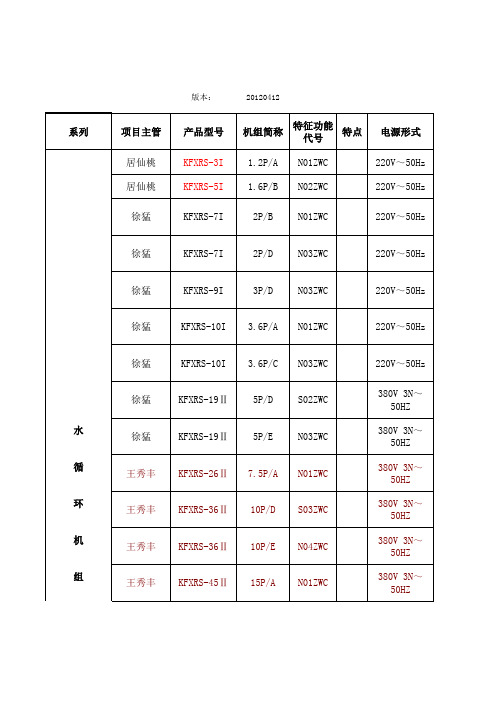
230
4.43
2370
3600W 11.2A
17A
2.5m³/h
10500
230
4.43
2370
3600W 11.2A
17A
2.5m³/h
19000
400
4.44
4280
6400W 7.6A
11A
3.5m³/h
19000
400
4.44
4280
6400W 7.6A
11A
3.5m³/h
25500
550
4.40
380V 3N~ 50HZ
380V 3N~ 50HZ
380V 3N~ 50HZ
机 组
王秀丰 KFXRS-68Ⅱ 20P/A N01ZWC
380V 3N~ 50HZ
王秀丰 KFXRS-75Ⅱ 25P/B N02ZWC
王秀丰 KFXRS-75Ⅱ 25P/D N04ZWC
王秀丰 王秀丰
KFXRS-90Ⅱ 30P/B
2P17S225ANQ 2P14S225ANE ZW61KA-TFP-
542
1-1/2"内 丝
≤62dB(A)
1600×900× 1160(mm)
450kg
R22 (3.3× 2)kg
谷轮
ZW61KA-TFP542
1-1/2"内 丝
≤64dB(A)
1800×1000× 1150(mm)
450kg
R22 (3.8× 2)kg
DN20
≤56dB(A)
680×600× 820(mm)
73kg
R22 1.3kg
三菱
TS33VDEC
DN25
hs1m二极管参数

hs1m二极管参数HS1M二极管是一种通用整流器二极管,其参数如下:1. 最大反向电压(Max Reverse Voltage):1000V2. 最大直流工作电流(Max DC Forward Current):1A3. 最大反向漏电流(Max Reverse Leakage Current):25μA4. 正向压降(Forward Voltage Drop):1.1V @ 1A5. 最大工作温度(Max Operating Temperature):150℃6. 封装形式(Package):DO-214ACHS1M二极管应用广泛,通常用于电源、无线电、通讯、家电等领域。
它的主要特点是耐压能力强,正向压降低,反向漏电流小,封装形式紧凑,易于安装。
除了以上技术参数,HS1M二极管的一些注意事项也需要注意:1. 在正向工作时,应防止过度驱动和过热2. 在安装前应仔细检查极性3. 应将二极管安装在散热器上,在高温环境下应增加散热措施4. 在使用过程中应避免机械损坏和静电损坏HS1M二极管是一种性能优良、应用范围广泛的通用整流器二极管,具有良好的耐压能力和较低的正向压降,其参数和注意事项需要用户在使用过程中严格遵守。
HS1M二极管是当前市场上较为常用的一种通用整流器二极管,广泛应用于电力、通信、计算机及其周边设备等领域。
它具有价格适中、性能稳定、可靠性高等特点,被广泛认可和应用。
本文将详细介绍HS1M二极管的性能特点、应用领域以及常见问题等相关内容,为用户提供参考。
1. 性能特点(1)耐压能力强:HS1M二极管的最大反向电压可达到1000V,使其在低压电源的应用中异常耐用。
(2)封装形式紧凑:HS1M二极管的封装形式为DO-214AC,体积较小,易于安装,在一些空间有限的场合显得尤为适用。
(3)正向压降低:HS1M二极管的正向压降仅为1.1V @ 1A,这意味着它能够在一定程度上降低功耗,提高整体效率。
伊顿马达样本

● 97 [ 5.9]
● 120 [ 7.3]
● 146 [ 8.9]
● 159 [ 9.7]
● 185 [11.3]
● 231 [14.1]
● 293 [17.9]
● 370 [22.6]
安装法兰
● 2 螺栓 (标准),支口直径 82,6 [3.25],安装孔径 13,59 [.535],孔分布圆直径 106,2 [4.18] B.C.
hs和t系列马达输出轴密封hs和t系列马达防腐蚀涂层hs和t系列马达速度传感器hs和t系列马达转动轻松的定转子低速阀配流hs和t马达均可供选择h系列s系列t系列技术指标见p8见p14见p20性能参数91115172125尺寸产品安装尺寸输出轴接口121826输出轴的径向载荷能力29输出轴尺寸3031安装尺寸工具3233壳体压力及泄油口3435131927产品号标准的推荐的液压油36其他所有资料请与伊顿公司代理商联系产品目录内容油口尺寸3334373839型号规格编码特殊订货hs和t系列马达带有低速配流阀的技术指标和产品号28轴的转向标准的121826轴的转向与标准相反的373839速度传感器3529303132333435363334282930313233343536333428358通用马达h系列技术指标连续不连续连续不连续最高转速rpm连续流量推荐的过滤精度据iso清洁度1813技术指
● 直径 1 英寸,直轴,月牙键,端部有 1/4-20 的螺纹孔 ● 直径 1 英寸,SAE 6B 花键,端部有 1/4-20 的螺纹孔 ● 直径 1 英寸,直轴,有- 7,9 [.31] 的垂直通孔,离端面 11,2 [.44] ● 直径 1 英寸,直轴,有- 10,2 [.40] 的垂直通孔,离轴端 15,7 [.62],端部还有一个 1/4-20 的螺纹孔 ● 直径 7/8 英寸,SAE B 13 T 花键 ● 直径 7/8 英寸,SAE B 直轴有方键 ● 直径 1 英寸,锥轴,月牙键,带螺母 ● 直径 25mm,直轴,8mm 平键,端部有 M8 x 1,2 螺纹孔 ● 直径 1 英寸,直轴,月牙键,端部 1/4-20 螺纹孔 (有防腐蚀保护层) ● 直径 25mm,直轴, 8mm 平键,及 M8 x 1,2 螺纹孔 (有防腐蚀保护层) ● 直径 1 英寸,直轴有 10,2 [.40] 直径的垂直通孔,离端面 15,7 [.62] 并端部还有 1/4-20 的螺纹孔 (有防
螺杆空压机URS

螺杆空压机U R S -CAL-FENGHAI-(2020YEAR-YICAI)_JINGBIAN------------------------42 范围-----------------------------------------------------------------------------------43 术语-----------------------------------------------------------------------------------44 法规和指南--------------------------------------------------------------------------55 描述-----------------------------------------------------------------------------------66 用户及系统要求--------------------------------------------------------------------76.1 系统能力--------------------------------------------------------------------------76.2 工艺要求--------------------------------------------------------------------------76.3 基本性能描述--------------------------------------------------------------------76.4 工艺过程-------------------------------------------------------------------------86.5 工艺关键控制参数/要求------------------------------------------------------86.6 材质与机械要求----------------------------------------------------------------86.7 系统关键部位/系统的要求-----------------------------------------------------96.8 电气--------------------------------------------------------------------------------13---------------------146.10 数据和安全---------------------------------------------------------------------166.11 设计、制造---------------------------------------------------------------------176.12DQ、FAT、SAT、IQ、OQ、PQ 要求-----------------------------------186.13 厂房设施及公共系统---------------------------------------------------------206.14 安全、环境---------------------------------------------------------------------206.15 清洁要求------------------------------------------------------------------------206.16 设备及材料运输要求---------------------------------------------------------206.17 服务与维修要求---------------------------------------------------------------216.18 文件------------------------------------------------------------------------------226.19 质量控制计划------------------------------------------------------------------246.20 质量保证和责任---------------------------------------------------------------246.21 约束条件------------------------------------------------------------------------256.22 附件------------------------------------------------------------------------------26附件 1 URS 符合性确认表格----------------------------------------------------26附件 2 元器件制造商清单确认--------------------------------------------------26附件 3 文件形成/提交时间(进度)表----------------------------------------26附件 4 技术参数表-----------------------------------------------------------------27附件 5 设计院提供的压缩空气系统平面布置图附件 6 设计院提供的空压机机房平面布置图1.目的 PURPOSE该文件旨在从项目和系统的角度阐述用户的需求,总括了用户对该项目的质量要求,符合相关规范、标准要求,描述了用户对该设备的工作过程及功能的期望。
Yilida SYP系列风机样本
Version Number: A201201 该手册最终解释权归亿利达公司所有
SYP
系列离心式空调风机 The Smart Air
亿利达 技术手册
The Smart Air
Fan Applications
风机应用部分
AMCA Introduction
AMCA 介绍
Quantities, Symbols and Units
量、符号与单位
Fan Basics and Applications
风机基础及应用
Fan Vibration and Balancing
风机的振动和平衡
The Basics of Sound
风机的声音基础
The Effects of Temperature and Altitude
温度与海拔对选型的影响ቤተ መጻሕፍቲ ባይዱ
- 1、下载文档前请自行甄别文档内容的完整性,平台不提供额外的编辑、内容补充、找答案等附加服务。
- 2、"仅部分预览"的文档,不可在线预览部分如存在完整性等问题,可反馈申请退款(可完整预览的文档不适用该条件!)。
- 3、如文档侵犯您的权益,请联系客服反馈,我们会尽快为您处理(人工客服工作时间:9:00-18:30)。
PartNO.:FYS-12011AX/BX-XX
ADD:NO.115QiXin Road NingBo Zhejiang China ZIP.:315051DESCRIPTION
●
30.60mm (1.2”)Single digit numeric display series.
●
Standard brightness.●Low current operation.
●Excellent character apperance.
●Easy mounting on P.C.boards or sockets
Package Dimensions &Internal Circuit Diagram
Notes:
·All dimensions are in millimeters (inches)
·Tolerance is ±0.25(0.01")unless otherwise noted.·Specificaions are subject to change whitout
notice.
PartNO.:FYS-12011AX/BX-XX
ADD:NO.115QiXin Road NingBo Zhejiang China ZIP.:315051:Absolute maximum ratings (Ta=25℃)
Value
Parameter Symbol Test Condition
Min
Max
Unit
Reverse V oltage VR IR=30μA 5-----V Forward
Current
IF -----------30mA Power Dissipation Pd -----------100mW Pulse Current Ipeak Duty=0.1mS,1KHz ------150mA Operating Temperature Topr ------40+85°C Storage Temperature
Tstr
-----
-40
+85
°C
■Description:
·Color Code &Chip characteristics:(Test Condition:IF=20mA)
Forward Voltage(VF)Unit:V Emitting Color Dice Material Peak
Wave
Length (λP )Spectral Line halfwidth(△
λ1/2)Typ Max Luminous Intensity (Iv)Unit:ucd H
Red GaP/GaP
700nm 90nm 2.25 2.50500S Hi Red GaAlAs/GaAs,SH 660nm 20nm 1.85 2.203500D Super Red GaAlAs/GaAs,DH 660nm 20nm 1.85 2.206000UR Ultra Red GaAlAs/GaAs,DD H
660nm 20nm 1.85 2.2012000E Orange GaAsP/GaP 635nm 35nm 2.10 2.502500Y Yellow GaAsP/GaP 585nm 35nm 2.10 2.502000G
Green
GaP/GaP
570nm
30nm
2.20
2.50
2500
·-XX:Surface /Lens color :
Number
1
2
3
4
5
Ref Surface Color White Black Gray Red Green Epoxy Color
Water clear
White diffused
Red Diffused
Green Diffused
Yellow Diffused
PartNO.:FYS-12011AX/BX-XX
ADD:NO.115QiXin Road NingBo Zhejiang China ZIP.:3150511.0
0.5
350
4004505005506006507007508008509009501000
(A)
(B)
(C)
(D)
(2)
(3)
(8)
(4)
(1)(6)
(5)
(9)
(10)
Wavelength(nm)
RELATIVE INTENSITY Vs WAVELENGTH()
λp (1)-GaAsP/GaAs 655nm/Red (2)-GaP 570nm/Yellow Green (3)-GaAsP/GaP 585nm/Yellow
(4)-GaAsp/GaP 635nm/Orange &Hi-Eff Red (5)-GaP 700nm/Bright Red
(6)-GaAlAs/GaAs 660nm/Super Red (8)-GaAsP/GaP 610nm/Super Red
(9)-GaAlAs 880nm
(10)-GaAs/GaAs &GaAlAs/GaAs 940nm (A)-GaN/SiC 430nm/Blue (B)-InGaN/SiC 470nm/Blue
(C)-(D)-InGaN/SiC 505nm/Ultra Green InGaAl/SiC 525nm/Ultra Green
504030201001.2
1.6
2.0 2.4 2.6
3.0
1
63
45
28
50403020100
20406080100
16
2,4,8,A 35
3210.50.20.1-30
-20
-10
10
20
30
40
50
60
70
15423
1098765432
1
1
10100100010,00010KHz 3KHz
1KHz 300KHz 100KHz F-REFRESH RATE
100KHz 30KHz
10KHz 3KHz 1KHz 300Hz 100Hz 1098765
4321
1
10100100010,000
FORWARD VOLT AGE (Vf)FORWARD CURRENT VS.FORWARD VOLTAGE
RELATIVE LUMINOUS
INTENSITY VS.FORWARD CURRENT
AMBIENT TEMPERATURE T a()℃FORWARD CURRENT VS.AMBIENT TEMPERATURE
tp-PULSE DURATION uS (1,2,3,4,6,8,B.D.J.K)
NOTE:25free air temperature unless otherwise specified
℃tp-PULSE DURATION uS
FORWARD CURRENT(mA)FORWARD CURRENT (mA)RELA TIVE LUMINOUS INTENSITY
FORWARD CURRENT(mA)
RELATIVE LUMINOUS INTENSITY
AMBIENT TEMPERATURE T a()
℃(5)
Ipeak MAX.IDC MAX.
Ipeak MAX.IDC MAX.
PartNO.:FYS-12011AX/BX-XX
ADD:NO.115QiXin Road NingBo Zhejiang China ZIP.:315051
tapy QTY/foam(pcs)QTY /Bundle (pcs)QTY /CARTONDimension
FYS-12011A/Bx-xx 5*6=3030*16=480480*4=1920。
