3SK323中文资料
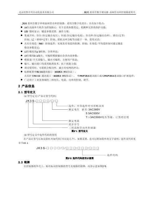
jk3s三相全数字调功器说明书
GB/T3859.1-93、GB/T3859.2-93
2.7 认证
北京佳凯中兴自动化技术有限公司的产品从设计、生产、服务等方面已通过 ISO9001 认证。
2.8 缩略语
RS485
通讯接口
MODBUS
通讯协议
PROFIBUS
现场总线规范(Process Field Bus)
RTU
MODBUS 的一种通讯模式
0
输入信号 DC1~5V
0 1 × × ××
0
DC0~20mA 1 1 × × ××
1
DC0~5V
0 1 × × ××
1
DC0~10V 0 0 × × ××
1
AI2
DC0~5V
× × 1 ×××
输入信号 DC0~10V × × 0 ×××
(2)开关量输入信号与SW1的拨码状态(×表示与拨码位无关)
端口
功能
说明
主回路端子
主回路电源
JK3S-****:3AC380V,30~65Hz
JK3S-****/5:3AC500V,30~65Hz
JK3S-****/T:>3AC500V,30~65Hz
主回路输出
连接负载
保护地
要求可靠接地
控制端子
控制电源
控制器工作电源;AC100~240V 45~65Hz
风机电源输入
模拟给定参考电源,负载能力<5mA
模拟输入1
DC0~20mA/DC4~20mA
输入阻抗:250Ω
DC0~5V/DC0~10V/DC1~5V 输入阻抗:25KΩ
可编程,光电隔离
通过拨码开关和参数设置(4.11菜单)选择信号类型
模拟输入2
MAX3232中文资料.pdf
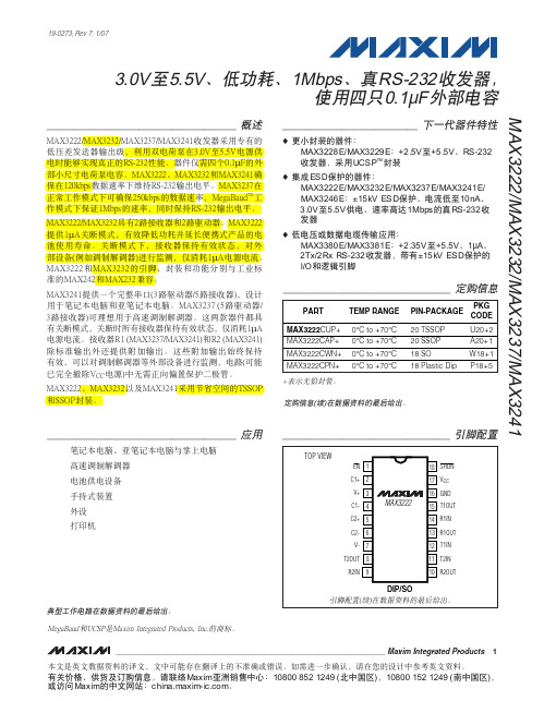
MAX3222/MAX3232/MAX3237/MAX32413.0V至5.5V、低功耗、1Mbps、真RS-232收发器,使用四只0.1µF外部电容________________________________________________________________Maxim Integrated Products119-0273; Rev 7; 1/07MegaBaud和UCSP是Maxim Integrated Products, Inc.的商标。
本文是英文数据资料的译文,文中可能存在翻译上的不准确或错误。
如需进一步确认,请在您的设计中参考英文资料。
有关价格、供货及订购信息,请联络Maxim亚洲销售中心:10800 852 1249 (北中国区),10800 152 1249 (南中国区),或访问Maxim的中文网站:。
M A X 3222/M A X 3232/M A X 3237/M A X 32413.0V至5.5V、低功耗、1Mbps、真RS-232收发器,使用四只0.1µF外部电容2_______________________________________________________________________________________ABSOLUTE MAXIMUM RATINGSELECTRICAL CHARACTERISTICS(V CC = +3.0V to +5.5V, C1–C4 = 0.1µF (Note 2), T A = T MIN to T MAX , unless otherwise noted. Typical values are at T A = +25°C.)Stresses beyond those listed under “Absolute Maximum Ratings” may cause permanent damage to the device. These are stress ratings only, and functional operation of the device at these or any other conditions beyond those indicated in the operational sections of the specifications is not implied. Exposure to absolute maximum rating conditions for extended periods may affect device reliability.Note 1:V+ and V- can have a maximum magnitude of 7V, but their absolute difference cannot exceed 13V.V CC ...........................................................................-0.3V to +6V V+ (Note 1)...............................................................-0.3V to +7V V- (Note 1)................................................................+0.3V to -7V V+ + V- (Note 1)...................................................................+13V Input VoltagesT_IN, SHDN , EN ...................................................-0.3V to +6V MBAUD...................................................-0.3V to (V CC + 0.3V)R_IN.................................................................................±25V Output VoltagesT_OUT...........................................................................±13.2V R_OUT....................................................-0.3V to (V CC + 0.3V)Short-Circuit DurationT_OUT....................................................................ContinuousContinuous Power Dissipation (T A = +70°C)16-Pin TSSOP (derate 6.7mW/°C above +70°C).............533mW 16-Pin Narrow SO (derate 8.70mW/°C above +70°C)....696mW 16-Pin Wide SO (derate 9.52mW/°C above +70°C)........762mW 16-Pin Plastic DIP (derate 10.53mW/°C above +70°C)...842mW 18-Pin SO (derate 9.52mW/°C above +70°C)..............762mW 18-Pin Plastic DIP (derate 11.11mW/°C above +70°C)..889mW 20-Pin SSOP (derate 7.00mW/°C above +70°C).........559mW 20-Pin TSSOP (derate 8.0mW/°C above +70°C).............640mW 28-Pin TSSOP (derate 8.7mW/°C above +70°C).............696mW 28-Pin SSOP (derate 9.52mW/°C above +70°C).........762mW 28-Pin SO (derate 12.50mW/°C above +70°C).....................1W Operating Temperature RangesMAX32_ _C_ _.....................................................0°C to +70°C MAX32_ _E_ _ .................................................-40°C to +85°C Storage Temperature Range.............................-65°C to +150°C Lead Temperature (soldering, 10s).................................+300°CMAX3222/MAX3232/MAX3237/MAX32413.0V至5.5V、低功耗、1Mbps、真RS-232收发器,使用四只0.1µF外部电容_______________________________________________________________________________________3TIMING CHARACTERISTICS—MAX3222/MAX3232/MAX3241(V CC = +3.0V to +5.5V, C1–C4 = 0.1µF (Note 2), T A = T MIN to T MAX , unless otherwise noted. Typical values are at T A = +25°C.)ELECTRICAL CHARACTERISTICS (continued)(V CC = +3.0V to +5.5V, C1–C4 = 0.1µF (Note 2), T A = T MIN to T MAX , unless otherwise noted. Typical values are at T A = +25°C.)A X 3222/M A X 3232/M A X 3237/M A X 32413.0V至5.5V、低功耗、1Mbps、真RS-232收发器,使用四只0.1µF外部电容4_______________________________________________________________________________________典型工作特性Ω, T A = +25°C, unless otherwise noted.)LOAD CAPACITANCE (pF)0246810121416182022150MAX3222/MAX3232SLEW RATEvs. LOAD CAPACITANCELOAD CAPACITANCE (pF)S L E W R A T E (V /µs )20003000100040005000510152025303540MAX3222/MAX3232SUPPLY CURRENT vs. LOAD CAPACITANCEWHEN TRANSMITTING DATALOAD CAPACITANCE (pF)S U P P L Y C U R R E N T (m A )20003000100040005000TIMING CHARACTERISTICS—MAX3237(V CC = +3.0V to +5.5V, C1–C4 = 0.1µF (Note 2), T A = T MIN to T MAX , unless otherwise noted. Typical values are at T A = +25°C.)Note 2:MAX3222/MAX3232/MAX3241: C1–C4 = 0.1µF tested at 3.3V ±10%; C1 = 0.047µF, C2–C4 = 0.33µF tested at 5.0V ±10%.MAX3237: C1–C4 = 0.1µF tested at 3.3V ±5%; C1–C4 = 0.22µF tested at 3.3V ±10%; C1 = 0.047µF, C2–C4 = 0.33µF tested at 5.0V ±10%.Note 3:Transmitter input hysteresis is typically 250mV.MAX3222/MAX3232/MAX3237/MAX32413.0V至5.5V、低功耗、1Mbps、真RS-232收发器,使用四只0.1µF外部电容_______________________________________________________________________________________5-7.5-5.0-2.502.55.07.50MAX3241TRANSMITTER OUTPUT VOLTAGEvs. LOAD CAPACITANCELOAD CAPACITANCE (pF)T R A N S M I T T E R O U T P U T V O L T A G E (V )2000300010004000500046810121416182022240MAX3241SLEW RATEvs. LOAD CAPACITANCELOAD CAPACITANCE (pF)S L E W R A T E (V /µs )20003000100040005000510152025303545400MAX3241SUPPLY CURRENT vs. LOADCAPACITANCE WHEN TRANSMITTING DATALOAD CAPACITANCE (pF)S U P P L Y C U R R E N T (m A )20003000100040005000-7.5-5.0-2.502.55.07.50MAX3237TRANSMITTER OUTPUT VOLTAGE vs. LOAD CAPACITANCE (MBAUD = GND)LOAD CAPACITANCE (pF)T R A N S M I T T E R O U T P U T V O L T A G E (V )200030001000400050000102030504060700MAX3237SLEW RATE vs. LOAD CAPACITANCE(MBAUD = V CC )LOAD CAPACITANCE (pF)S L E W R A T E (V /µs )500100015002000-7.5-5.0-2.502.55.07.50MAX3237TRANSMITTER OUTPUT VOLTAGE vs. LOAD CAPACITANCE (MBAUD = V CC )LOAD CAPACITANCE (pF)T R A N S M I T T E R O U T P U T V O L T A G E (V )5001000150020001020304050600MAX3237SUPPLY CURRENT vs.LOAD CAPACITANCE (MBAUD = GND)LOAD CAPACITANCE (pF)S U P P L Y C U R R E N T (m A )200030001000400050000246810120MAX3237SLEW RATE vs. LOAD CAPACITANCE(MBAUD = GND)LOAD CAPACITANCE (pF)S L E W R A T E (V /µs )2000300010004000500010302040506070MAX3237SKEW vs. LOAD CAPACITANCE(t PLH - t PHL )LOAD CAPACITANCE (pF)1000150050020002500____________________________________________________________________典型工作特性(续)(V CC = +3.3V, 235kbps data rate, 0.1µF capacitors, all transmitters loaded with 3k Ω, T A = +25°C, unless otherwise noted.)M A X 3222/M A X 3232/M A X 3237/M A X 32413.0V至5.5V、低功耗、1Mbps、真RS-232收发器,使用四只0.1µF外部电容6_________________________________________________________________________________________________________________________________________________________________引脚说明MAX3222/MAX3232/MAX3237/MAX32413.0V至5.5V、低功耗、1Mbps、真RS-232收发器,使用四只0.1µF外部电容_______________________________________________________________________________________7_______________________________详细说明双电荷泵电压转换器MAX3222/MAX3232/MAX3237/MAX3241的内部电源由两路稳压型电荷泵组成,只要输入电压(V CC )在3.0V至5.5V范围以内,即可提供+5.5V (倍压电荷泵)和-5.5V (反相电荷泵)输出电压。
[VIP专享]三专两闭锁.
![[VIP专享]三专两闭锁.](https://img.taocdn.com/s3/m/5b56f9924028915f804dc2b8.png)
三专两闭锁 “三专”指井工开采的矿井井下对局部通风机供电采用专用变压器、专用开关、专用线路,以确保供电相对稳定,保证停头不停风的原则。
“两闭锁”指掘进工作面瓦斯电闭锁和风电闭锁。
其中瓦斯电闭锁是指当掘进工作面瓦斯浓度超限时,声光报警并自动切断工作面迎头被控设备电源;风电闭锁是指当局部主通风机停止运转或风筒风量低于规定值时,自动切断掘进工作面内(除备用风机电源外的)所有设备电源。
简要的就是指:三专即:专用变压器,专用线路,专用开关。
两闭锁即:风电闭锁,瓦斯电闭锁。
专业地讲:“一坡三挡”就是指为保证煤矿轨道运输安全,用以防止发生跑车事故而使用的预防和防止手段。
其手段包括防跑车装置与跑车防护装置,可能还应该包括矿车制动器。
什么是“一坡三挡” ? 简单讲就是:一、平台阻车器,二、变坡点下20米的挡车器,三、坡底的挡车栏。
“一坡三挡”的组成: (一)上部车场接近变坡点处安设自动复位式(或联动式)阻车器。
(二)变坡点下约一列车的长度处安装第一道跑车防护装置。
(《煤矿安全规程》中称为挡车栏)。
(三)在斜巷内根据巷道运输实际工况(巷道坡度、串车质量等)逐级安装跑车防护装置。
往深里讲:“一坡三挡”还应该是指一种关于保证轨道运输安全的一种管理方法。
注意:“轨道运输安全”是比“斜坡运输安全”更宽泛的概念。
需要指出的是:“一坡三挡”是来自《煤矿安全规程》规程第三百七十条倾斜井巷内使用串车提升是必须遵守下列规定: (一)在倾斜井巷内安设能够将运行中的断绳、脱钩的车辆阻止 住的跑车防护装置。
(二)在各车场安设能够防止带绳车辆误入非运行车场或区段的 阻车器。
(三)在上部平车场入口安设能够控制车辆进入摘挂钩地点的阻 车器。
(四)在上部平车场接近变坡点处,安设能够阻止未连挂的车辆 滑入斜巷的阻车器。
(五)在变坡点下方略大于1列车长度的地点,设置能够防止未连 挂的车辆继续往下跑车的挡车栏。
(六)在各车场安设甩车时能发出警号的信号装置。
中走丝培训资料(SKD3_XP版)
中走丝线切割机床SKD3-WINDOWS培训资料苏州三光机电销售有限公司2012年2月目录第一章电火花线切割机研究简况电火花线切割机研究简况 (03)第二章SKD3 电火花线切割机床控制机一故障提示排除 (04)二加工步骤 (06)1.开机 (06)2.线控盒 (06)3.上丝 (07)4.紧丝 (07)5.工件装夹 (07)6.对边及定中心 (07)7.运行 (09)三系统菜单 (11)1.文件 (11)2.移动 (13)3.设置 (15)4.编程 (18)5.M D I (27)第三章加工注意事项及维护保养加工注意事项及维护保养 (28)电火花线切割机研究简况电火花线切割加工法是在1955年首先由苏联发表,1957年苏联首先研制出A207型光电跟踪电火花线切割机,1965年苏联研制出数字控制电火花线切割机NC-WEDM,1969年瑞士研制成功数控电火花线切割机,日本在1972年由西部电机株式会社推出EW-20型数控电火花线切割机,目前除苏联、瑞士及日本外美国也生产线切割机。
我国是世界上最早生产电火花线切割机的国家之一,早在1958年我国便开始设计研制简易线切割机,1961年我国研制成功靠模控制电火花线切割机,1967年我国研制成功第一台数控电火花线切割机,当时的数控机是采用分立元件的一种专用计算机,也就是大家称为第一代的数控机。
三光公司是我国最早生产电火花线切割机的企业之一。
早在1970年研制成功GDX-Ⅰ型光电跟踪电火花线切割机,1975推出的GDX-Ⅱ型光电跟踪电火花线切割机,1976年研制SSX-Ⅱ型数控电火花线切割机,采用DTL集成电路,以后又研制SSX-Ⅲ型数控电火花线切割机,数控系统采用PMOS集成电路,称为第二代数控机,1982年又研制成功DK7725d型由单板微机控制的第三代数控电火花线切割机CNC-WEDM,1984年荣获国家银质奖,1985年、1986年又继续开发了可调线架的DK7725f型数控电火花线切割机和DK7725e型带斜度加工的数控电火花线切割机。
LM323K中文资料
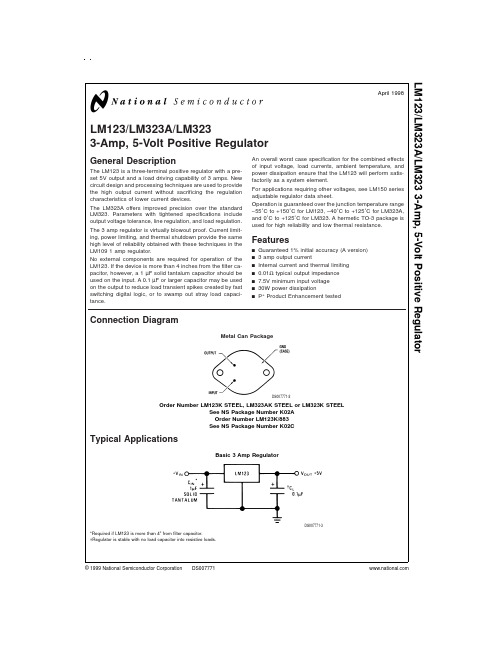
LM123/LM323A/LM3233-Amp,5-Volt Positive RegulatorGeneral DescriptionThe LM123is a three-terminal positive regulator with a pre-set 5V output and a load driving capability of 3amps.New circuit design and processing techniques are used to provide the high output current without sacrificing the regulation characteristics of lower current devices.The LM323A offers improved precision over the standard LM323.Parameters with tightened specifications include output voltage tolerance,line regulation,and load regulation.The 3amp regulator is virtually blowout proof.Current limit-ing,power limiting,and thermal shutdown provide the same high level of reliability obtained with these techniques in the LM1091amp regulator.No external components are required for operation of the LM123.If the device is more than 4inches from the filter ca-pacitor,however,a 1µF solid tantalum capacitor should be used on the input.A 0.1µF or larger capacitor may be used on the output to reduce load transient spikes created by fast switching digital logic,or to swamp out stray load capaci-tance.An overall worst case specification for the combined effects of input voltage,load currents,ambient temperature,and power dissipation ensure that the LM123will perform satis-factorily as a system element.For applications requiring other voltages,see LM150series adjustable regulator data sheet.Operation is guaranteed over the junction temperature range −55˚C to +150˚C for LM123,−40˚C to +125˚C for LM323A,and 0˚C to +125˚C for LM323.A hermetic TO-3package is used for high reliability and low thermal resistance.Featuresn Guaranteed 1%initial accuracy (A version)n 3amp output currentn Internal current and thermal limiting n 0.01Ωtypical output impedance n 7.5V minimum input voltage n 30W power dissipationnP +Product Enhancement testedConnection DiagramTypical ApplicationsMetal Can PackageDS007771-2Order Number LM123K STEEL,LM323AK STEEL or LM323K STEELSee NS Package Number K02A Order Number LM123K/883See NS Package Number K02CBasic 3Amp RegulatorDS007771-3*Required if LM123is more than 4"from filter capacitor.†Regulator is stable with no load capacitor into resistive loads.April 1998LM123/LM323A/LM3233-Amp,5-Volt Positive Regulator©1999National Semiconductor Corporation Absolute Maximum Ratings(Note1)If Military/Aerospace specified devices are required, please contact the National Semiconductor Sales Office/ Distributors for availability and specifications.(Note5)Input Voltage20V Power Dissipation Internally Limited Operating Junction Temperature RangeLM123−55˚C to+150˚C LM323A−40˚C to+125˚C LM3230˚C to+125˚C Storage Temperature Range−65˚C to+150˚C Lead Temperature(Soldering,10sec.)300˚C ESD Tolerance(Note5)2000VLM123Electrical Characteristics(Note2)Parameter Conditions LM123UnitsMin Typ Max Output Voltage T j=25˚C 4.75 5.3VV IN=7.5V,I OUT=0A7.5V≤V IN≤15V 4.6 5.4V0A≤I OUT≤3A,P≤30WLine Regulation(Note4)T j=25˚C525mV7.5V≤V IN≤15VLoad Regulation(Note4)T j=25˚C,V IN=7.5V,25100mV0A≤I OUT≤3AQuiescent Current7.5V≤V IN≤15V,1220mA0A≤I OUT≤3AOutput Noise Voltage T j=25˚C40µVrms10Hz≤f≤100kHzShort Circuit Current Limit T j=25˚CV IN=15V3 4.5AV IN=7.5V45A Long Term Stability35mV Thermal Resistance Junctionto Case(Note3)2˚C/W LM323A/LM323Electrical Characteristics(Note2)Parameter Conditions LM323A LM323UnitsMin Typ Max Min Typ MaxOutput Voltage T j=25˚C 4.955 5.05 4.85 5.2VV IN=7.5V,I OUT=0A7.5V≤V IN≤15V 4.85 5.15 4.75 5.25V0A≤I OUT≤3A,P≤30WLine Regulation(Note4)T j=25˚C510525mV7.5V≤V IN≤15VLoad Regulation(Note4)T j=25˚C,V IN=7.5V,255025100mV0A≤I OUT≤3AQuiescent Current7.5V≤V IN≤15V,12201220mA0A≤I OUT≤3AOutput Noise Voltage T j=25˚C4040µVrms10Hz≤f≤100kHzShort Circuit Current Limit T j=25˚CV IN=15V3 4.53 4.5AV IN=7.5V4645A Long Term Stability3535mV Thermal Resistance Junctionto Case(Note3)22˚C/W 2LM323A/LM323Electrical Characteristics(Note2)(Continued)Note1:“Absolute Maximum Ratings”indicate limits beyond which damage to the device may occur.Operating Ratings indicate conditions for which the device is functional,but do not guarantee specific performance limits.Note2:Unless otherwise noted,specifications apply for−55˚C≤T j≤+150˚C for the LM123,−40˚C≤T j≤+125˚C for the LM323A,and0˚C≤T j≤+125˚C for the LM323.Although power dissipation is internally limited,specifications apply only for P≤30W.Note3:Without a heat sink,the thermal resistance of the TO-3package is about35˚C/W.With a heat sink,the effective thermal resistance can only approach the specified values of2˚C/W,depending on the efficiency of the heat sink.Note4:Load and line regulation are specified at constant junction temperature.Pulse testing is required with a pulse width≤1ms and a duty cycle≤5%.Note5:Refer to RETS123K drawing for LM123K military specifications.Note6:Human body model,1.5kΩin series with100pF.Typical Performance CharacteristicsMaximum Average Power Dissipation for LM123DS007771-9Maximum Average PowerDissipation for LM323A,LM323DS007771-10Output ImpedanceDS007771-11Peak Available Output CurrentDS007771-12Short Circuit CurrentDS007771-13Ripple RejectionDS007771-14Dropout VoltageDS007771-15Line Transient ResponseDS007771-16Output VoltageDS007771-17 3Typical Performance Characteristics(Continued)Typical ApplicationsQuiescent CurrentDS007771-18Load Transient ResponseDS007771-19Output Noise VoltageDS007771-2010Amp Regulator with Complete Overload ProtectionDS007771-6 *Select for20mA Current from Unregulated Negative Supply4Typical Applications(Continued)Adjustable Regulator0V−10V@3ADS007771-7A1—LM101AC1—2µF Optional—Improves Ripple Rejection,Noise,and Transient ResponseTrimming Output to5VDS007771-8Adjustable Output5V−10V0.1%RegulationDS007771-4*Select to Set Output Voltage**Select to Draw25mA from V−5Schematic DiagramDS007771-1 6Physical Dimensions inches(millimeters)unless otherwise notedMetal Can Package(K)Order Number LM123K STEEL,LM323AK STEEL or LM323K STEELNS Package Number K02A7Physical Dimensionsinches (millimeters)unless otherwise noted (Continued)LIFE SUPPORT POLICYNATIONAL’S PRODUCTS ARE NOT AUTHORIZED FOR USE AS CRITICAL COMPONENTS IN LIFE SUPPORT DEVICES OR SYSTEMS WITHOUT THE EXPRESS WRITTEN APPROVAL OF THE PRESIDENT AND GENERAL COUNSEL OF NATIONAL SEMICONDUCTOR CORPORATION.As used herein:1.Life support devices or systems are devices or systems which,(a)are intended for surgical implant into the body,or (b)support or sustain life,and whose failure to perform when properly used in accordance with instructions for use provided in the labeling,can be reasonably expected to result in a significant injury to the user.2.A critical component is any component of a life support device or system whose failure to perform can be reasonably expected to cause the failure of the life support device or system,or to affect its safety or effectiveness.National Semiconductor Corporation AmericasTel:1-800-272-9959Fax:1-800-737-7018Email:support@National Semiconductor EuropeFax:+49(0)180-5308586Email:europe.support@Deutsch Tel:+49(0)180-5308585English Tel:+49(0)180-5327832Français Tel:+49(0)180-5329358Italiano Tel:+49(0)180-5341680National Semiconductor Asia Pacific Customer Response Group Tel:65-2544466Fax:65-2504466Email:sea.support@National Semiconductor Japan Ltd.Tel:81-3-5639-7560Fax:81-3-5639-7507Metal Can Package (K)Mil-Aero ProductOrder Number LM123K/883NS Package Number K02CL M 123/L M 323A /L M 3233-A m p ,5-V o l t P o s i t i v e R e g u l a t o rNational does not assume any responsibility for use of any circuitry described,no circuit patent licenses are implied and National reserves the right at any time without notice to change said circuitry and specifications.。
2SK3233中文资料

Forward transfer admittance |yfs|
3.0
Input capacitance
Ciss
—
Output capacitance
Coss —
Reverse transfer capacitance Crss —
Turn-on delay time
td(on) —
Rise time
ID = 2.5 A, VDS = 10 V Note4 VDS = 25 V VGS = 0 f = 1 MHz ID = 2.5 A VGS = 10 V RL = 100 Ω Rg = 10 Ω VDD = 400 V VGS = 10 V ID = 5 A IF = 5 A, VGS = 0
tr
—
Turn-off delay time
td(off) —
Fall time
tf
—
Total gate charge
Qg
—
Gate to source charge
Qgs
—
Gate to drain charge
Qgd
—
Body-drain diode forward voltadiode reverse
Reverse Drain Current vs. Source to Drain Voltage 10
8
5, 10 V
6
VGS = 0 V
4
2
Pulse Test
0
0.4 0.8 1.2 1.6 2.0
Source to Drain Voltage VSD (V)
2SK3233
Gate to Source Cutoff Voltage vs. Case Temperature
DK32

RE入口/RA出口压力调节器的作用: ● RE压力调节器确保在入口压力波动的情况下
使输出流量保持稳定
● RA压力调节器确保在出口压力波动的情况下 使输出流量保持稳定
3
DK32 DK34 DK37
3. 认证
标准
GB3836.1-2000 GB3836.4-2000
Φ8
168
90 168
70
Φ8
入口1/4NPT
入口1/4NPT 70 Φ90
4.5.2 压力调节器的应用 在介质压力波动较大的场合,为了使DK系列流量计能够得到稳定准确的测量与流量输出,要选择与其
配套的压力调节器(恒流器)。它能保证在介质压力发生变化时,流量显示和测量不受影响。 RE型用于稳定入口气体或液体的压力变化,保证指示和输出流量稳定(对于液体也适用于出口压力的
23
0.91
大约200 大约7.9 70 2.8
23
0.91
大约230 大约9.1 70 2.8
23
0.91
DK32带出口压力调节器
DK37/M8E带入口压力调节器
b
DK32带入口压力调节器
DK37/M8E和M8M带入口压力调节器
1/4"NPT b
c
d 1/4"NPT a
1/4"NPT b
c
d 1/4"NPT a
● 最大流量:空气4000l/h或者水为160l/h ● 压力等级:标准型:2.5bar, 特殊要求
6.4bar-10.0bar ● 温度最高到:80℃-150℃(特殊:280℃)
RE 型(应用于入口压力变化)
Φ90
出口1/4NPT
RA 型(应用于出口压力变化)
大连第三仪表联合制造公司二分厂产品型号说明说明书

一 产品型号说明J D L310表示规格110710L 表示为直行程执行器R 表示为角行程执行器D 表示为电子式J 表示为经济式二 产品主要特点1执行器本身具有伺服功能无需另配伺服放大器2关键部件控制器采用先进的混合集成电路并用树脂浇铸固化经老化处理可靠性高防潮防震3 用电位器调整零点行程灵敏度方便易行 4用跳线器任意选择正反动作 5断电源或断信号阀门自锁三 型号与规格表一类别 型号 输出力N速度mm/s行程 JDL 310 4000 1.25 101625 JDL 410 6400 1.25 4060直行程JDL510 16000 1.58 60100类别型号 输出力矩NM 全行程时间S 最大转角度JDR 110 40 25 JDR 210 100 25 JDR 310 250 25 JDR 410 600 25 JDR 510 1600 25 JDR 610 4000 40角行程JDR710 60006090四主要技术参数输入标准信号DC420mA开度反馈信号DC420mA反应时间1秒基本误差 2.0%开度检测精密导电塑料电位器电源电压220V AC 50Hz使用环境温度10 +55使用相对湿度普通型95%以下防爆型4585%环境气体无腐蚀性气体允许振动 1.5G以下信号线与电源线隔离信号线应选用屏蔽控制电缆4芯S=0.75mm²外径91电源线选用电缆2芯S=1.0mm²外径91防护等级IP55防爆等级ExdIIBT4手动机构手柄或手轮五工作原理JDL JDR系列电子式电动执行器是以220V单相交流作为驱动电源接受来自计算机调节器或操作器的DC420mA输入信号来工作的全电子式电动执行机构电子控制单元采用集成电路制作被设计成匣子并用树脂浇铸固化称为控制器本身具有伺服功能控制器部分接受的输入信号DC420mA和来自开度检测部分的开度信号将两信号相比并放大向消除其差值的方向驱动和控制电机使减速输出轴朝着减少这一偏差信号的方向转动直到开度信号和输入信号相等为止此时输出轴就稳定在与输入信号相对应的位置上由于二相伺服电动机采用杠杆式制动机构能保证在断电是迅速的制动从而改善了系统的稳定性并能限制执行器的惯性惰走消除负载反馈的影响本伺服电动机又由于转子电阻较大因而其机械特性较软保证了本执行器因系统事故而卡住时电机不被烧毁阀位反馈两个端子如不接线时请用250500电阻短接调行程和调零操作如下表二表二跳线器上位时安装为反作用调节方式直行程执行器角行程执行器给定信号增大输出轴向上行输出轴逆时针转动顺时针调零输出轴向下行输出轴顺时针转动顺时针调行程输出轴向上行输出轴逆时针转动跳线器下位时安装为正作用调节方式直行程执行器角行程执行器给定信号增大输出轴向下行输出轴顺时针转动顺时针调零输出轴向上行输出轴逆时针转动顺时针调行程输出轴向下行输出轴顺时针转动顺时针调灵敏度正反作用均相同灵敏度降低六电动执行器故障及检查办法1不动作但控制电源和信号灯均亮检查• 电源电压是否正确• 电动机是否断线• 电动机电位器电容各接插头是否良好• 在上述检查都无问题情况下用对比互换法判断控制器是否良好2不动作电源灯亮信号灯不亮检查 • 输入信号是否正确• 输入信号+极性是否接反• 在上述检查都无问题情况下用对比互换法判断控制器是否良好3电动机发热一天内可能有几次停止动作检查• 配套阀门允许压差是否在额定范围内• 零位和行程调整是否正确• 灵敏度是否过高• 环境湿度是否过高4电动机发热迅速震荡爬行短时间内停止动作检查• 用数字方式万用表交流2伏电压档测控制器输入端是否有交流干扰• 信号线是否采用屏蔽线是否与电源线隔离• 电位器及电位器配线是否良好• 反馈组件动作是否正常5执行器动作呈步行爬行现象动作缓慢检查• 检查操作器来信号的动作时间是否正确6位置反馈信号太大或太小检查• 零位和行程调整是否正确• 更换控制器判断七安装和使用注意事项1执行机构应安装在环境温度为10+50相对湿度95%无腐蚀性气体的环境中安装位置应考虑到手动操作及维修安装的方便执行机构输出轴与调节机构阀门等的连接可通过连杆支架及专用的连接头安装时必须避免所有结合处的松动间隙止挡限位应在输出轴的有效转角或行程范围内紧固不可松动执行机构的外形及安装尺寸见图三图四表三表四2特别注意隔爆型执行器的安装及使用产品的选用安装必须严格按照中华人民共和国危险场所安全规程的规定内外接地牢固可靠维修时断开电源后盖连接电源的接线端子爬电距离及电气间隙应大于8mm定期检查密封圈的老化问题如已老化应及时更换更换零件须到生产厂购买不得借用其它元件产品外壳保持清洁其最高表面温度不得超过1303为避免电源线的干扰信号线请采用屏蔽电缆线并与电源线隔离4安装场所若受辐射热直射日光的影响超出允许范围时请用适当遮蔽板或隔热材料进行保护5安装及运输时切勿承受猛烈冲动震动避免跌落等现象6安装前请不要拆卸配线入口塞子和护罩保管时避免灰尘及高温潮湿气体等场所7室外安装请不要在雨天配线作业8电源配线要有足够的容量以满足执行器额定电流及起动电流的要求9请安装地线连接电源及信号线时请先切断电源以防触电10安装时请留足执行器调整及检修时拆卸护罩所需要的空间并兼顾出口的方向11根据调节系统要求对执行机构进行整定然后可接入调节系统再投入运行前在投入运行前应检查现场的电源电压是否与规定相符按规定的电气安装接线图检查所有接线是否正确各接线端子是否牢靠12输出轴力或力矩应和终端调节机构阀门等所需力或力矩相适应以防止过载13电动执行器各组成部分应根据现场使用条件定期检查和高速减速器应定期清洗加油八外型尺寸图表JDL型系列直行程电子式电动执行器外形见图三外形尺寸见表三执行机构外形尺寸图三JDR型系列角行程电子式电动执行器外形及尺寸见图四,表四图四九手动机构执行机构后端盖上装有手柄如将手柄拨到手动位置可是制动盘和制动轮脱开可实现执行机构就地手动操作如将手柄拨到电动位置可保证执行器在自动运行时可靠的启动与停止执行机构就地手动操作只能在断电时进行不允许在伺服电动机通电的情况下进行手动操作执行机构就地手动操作时将电机上的手把拨在手动位置拉出手轮摇动即可操作完毕后先将电机上的手把拨到自动位置再把手轮推进如配有操作器可将操作器打在手动档在操作器上直接手动操作十定货须知及其它1订货须知请参照产品型号说明的内容填写产品名称型号规格以及输入信号注明是否配电子式电动操作器2其它电动执行器应放在干燥通风无腐蚀性气体的地方而且环境温度和相对温度应符合技术要求自发货时起十八个月内仪表如有损坏若属于厂方制造质量问题则由厂方负责免费保修若属于用户保管使用不当而造成的则由用户负责企业宗旨质量第一.信誉第一.服务第一 .新雪仪表 . 控制世界电话0411---3325668传真0411---3325168E-mail:****************。
CDSOD323-T03中文资料

ID
5
5
5
5
2
2
1
1
µA
CJ
3
pF
Notes: 1. Part numbers with suffix “C” indicate bidirectional device, i.e. CDSOD323-T05C. 2. For bidirectional devices only, the electrical specifications apply in both directions.
VF
24.0
24.0
29.0
29.0
43.0
43.0
V
VC
31.8 V 31.8 V 45.0 V 45.0 V 56.0 V 56.0 V
V
@ 10 A @ 10 A @ 8 A @ 8 A @ 6 A @ 6 A
ID
1
µA
CJ
3
pF
Notes: 1. Part numbers with suffix “C” indicate bidirectional device, i.e. CDSOD323-T05C. 2. For bidirectional devices only, the electrical specifications apply in both directions.
元器件交易网
CDSOD323-TxxC – TVS Diode Array Series
Electrical & Thermal Characteristics (@ TA = 25 °C Unless Otherwise Noted)
Parameter
Symbol
3C3系列说明书

完善的N+X并机功能:无需特别机种,或是使用庞大的并机柜,只要每台3C3 UPS加装一块并机卡,就可以最多并接8台3C3 UPS,而且是直接将每台UPS输出并接在一起的真正并机,因为每一台都可以并机,而且不需要并机柜,所以就并机的弹性,时间或进度的配合,都是最方便的。同时每台UPS都是均流输出,所以非常适合使用在N+X冗余应用,或是扩充容量的应用上。
PPVIS接口提供给专业技术人员使用,透过PPVIS技术人员可以对UPS进行更深入的参数设置,满足少数用户的特殊使用。也可以经由PPVIS使技术人员获得进一步的UPS工作参数资料,对于UPS的状况可以更清楚的掌握
技术参数
型号
3C3-20KS /-ISO*
3C3-30KS /-ISO*
3C3-40KS /-ISO*
功率因数
0.95以上
隔离
否/是
输
出
电压
380VAC/220VAC(3Ф4W)
功率因数
0.8
电压稳定度
± 1%
非市电同步频率稳定度
± 0.1%
不平衡负载100% Nhomakorabea过载120% 10min,150% 30s
电
池
标称电压
384VDC
额定充电电压
432VDC
环
境
工作温度
0℃~40℃
储存温度
- 25℃~+55℃
此外,为提高维修保养的方便性,与兼顾成本、可靠度的考虑,3C3是采用类模块化的设计,将每相的功率部份,整合在同一块PC板上,但又不是全模块化的高成本及多接触点的设计,接触点一多,可靠度自然可能降低,因此,3C3扬弃全模块化的设计,而采用类模块化的设计。
KSC3503DSTU中文资料

2SC3503/KSC3503 — NPN Epitaxial Silicon Transistor2SC3503/KSC3503 — NPN Epitaxial Silicon TransistorElectrical Characteristics* T a =25°C unless otherwise noted* Pulse Test: Pulse Width ≤300µs, Duty Cycle ≤2%Ordering Information* 1. Affix “-S-” means the standard TO126 Package.(see package dimensions). If the affix is ”-STS-” instead of “-S-”, that mean the short-lead TO126 package. 2. Suffix “-TU” means the tube packing, The Suffix “TU” could be replaced to other suffix character as packing method.SymbolParameterTest ConditionMin.Typ.Max.UnitsBV CBO Collector-Base Breakdown Voltage I C = 10µA, I E = 0300V BV CEO Collecto- Emitter Breakdown Voltage I C = 1mA, I B = 0300V BV EBO Emitter-Base Breakdown Voltage I E = 10µA, I C = 05VI CBO Collector Cut-off Current V CB = 200V, I E = 00.1µA I EBO Emitter Cut-off Current V EB = 4V, I C = 00.1µAh FE DC Current GainV CE = 10V, I C = 10mA 40320 V CE (sat) Collector-Emitter Saturation Voltage I C = 20mA, I B = 2mA 0.6V V BE (sat) Base-Emitter Saturation Voltage I C = 20mA, I B = 2mA 1V f TCurrent Gain Bandwidth Product V CE = 30V, I C = 10mA 150MHz C ob Output CapacitanceV CB = 30V, f = 1MHz 2.6pF C reReverse Transfer CapacitanceV CB = 30V, f = 1MHz1.8pFPart Number*MarkingPackagePacking MethodRemarks2SC3503CSTU 2SC3503C TO-126TUBE hFE1 C grade 2SC3503DSTU 2SC3503D TO-126TUBE hFE1 D grade 2SC3503ESTU 2SC3503E TO-126TUBE hFE1 E grade 2SC3503FSTU 2SC3503F TO-126TUBE hFE1 F grade KSC3503CSTU C3503C TO-126TUBE hFE1 C grade KSC3503DSTU C3503D TO-126TUBE hFE1 D grade KSC3503ESTU C3503E TO-126TUBE hFE1 E grade KSC3503FSTUC3503FTO-126TUBEhFE1 F grade2SC3503/KSC3503 — NPN Epitaxial Silicon Transistor2SC3503/KSC3503 NPN Epitaxial Silicon Transistor2SC3503/KSC3503Rev. I31TRADEMARKSThe following are registered and unregistered trademarks and service marks Fairchild Semiconductor owns or is authorized to use andis not intended to be an exhaustive list of all such trademarks.DISCLAIMERFAIRCHILD SEMICONDUCTOR RESERVES THE RIGHT TO MAKE CHANGES WITHOUT FURTHER NOTICE TO ANY PRODUCTS HEREIN TO IMPROVE RELIABILITY, FUNCTION, OR DESIGN. FAIRCHILD DOES NOT ASSUME ANY LIABILITY ARISING OUT OF THE APPLICATION OR USE OF ANY PRODUCT OR CIRCUIT DESCRIBED HEREIN; NEITHER DOES IT CONVEY ANY LICENSE UNDER ITS PATENT RIGHTS, NOR THE RIGHTS OF OTHERS. THESE SPECIFICATIONS DO NOT EXPAND THE TERMS OF FAIRCHILD’S WORLDWIDE TERMS AND CONDITIONS, SPECIFICALLY THE WARRANTY THEREIN, WHICH COVERS THESE PRODUCTS.LIFE SUPPORT POLICYFAIRCHILD’S PRODUCTS ARE NOT AUTHORIZED FOR USE AS CRITICAL COMPONENTS IN LIFE SUPPORT DEVICES OR SYSTEMS WITHOUT THE EXPRESS WRITTEN APPROVAL OF FAIRCHILD SEMICONDUCTOR CORPORATION.As used herein:1. Life support devices or systems are devices or systemswhich, (a) are intended for surgical implant into the body, or (b) support or sustain life, and (c) whose failure to perform when properly used in accordance with instructions for use provided in the labeling, can be reasonably expected to result in significant injury to the user.2.A critical component is any component of a life support device or system whose failure to perform can be reasonably expected to cause the failure of the life support device or system, or to affect its safety or effectiveness.PRODUCT STATUS DEFINITIONS Definition of Terms ACEx ®Build it Now™CorePLUS™CROSSVOLT ™CTL™Current Transfer Logic™EcoSPARK ®Fairchild ®Fairchild Semiconductor ®FACT Quiet Series™FACT ®FAST ®FastvCore™FPS™FRFET ®Global Power Resource SMGreen FPS™Green FPS™ e-Series™GTO™i-Lo ™IntelliMAX™ISOPLANAR™MegaBuck™MICROCOUPLER™MicroFET™MicroPak™MillerDrive™Motion-SPM™OPTOLOGIC ®OPTOPLANAR ®®PDP-SPM™Power220®Power247®POWEREDGE ®Power-SPM™PowerTrench ®Programmable Active Droop™QFET ®QS™QT Optoelectronics™Quiet Series™RapidConfigure™SMART START™SPM ®STEALTH™SuperFET™SuperSOT™-3SuperSOT™-6SuperSOT™-8SyncFET™The Power Franchise ®TinyBoost™TinyBuck™TinyLogic ®TINYOPTO™TinyPower™TinyPWM™TinyWire™µSerDes™UHC ®UniFET™VCX™Datasheet Identification Product Status DefinitionAdvance InformationFormative or In DesignThis datasheet contains the design specifications for product development. Specifications may change in any manner without notice.Preliminary First ProductionThis datasheet contains preliminary data; supplementary data will be pub-lished at a later date. Fairchild Semiconductor reserves the right to make changes at any time without notice to improve design.No Identification Needed Full ProductionThis datasheet contains final specifications. Fairchild Semiconductor reserves the right to make changes at any time without notice to improve design. Obsolete Not In ProductionThis datasheet contains specifications on a product that has been discontin-ued by Fairchild semiconductor. The datasheet is printed for reference infor-mation only.。
3SK322中文资料
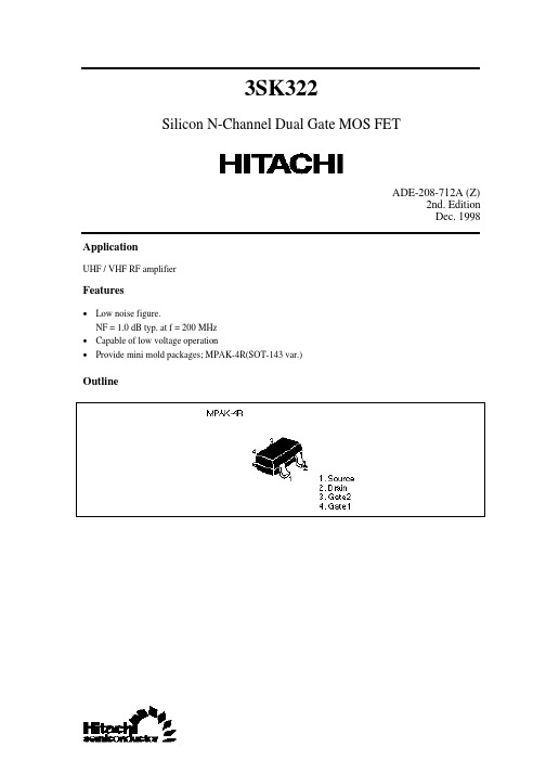
3SK322
Silicon N-Channel Dual Gate MOS FET
ADE-208-712A (Z) 2nd. Edition Dec. 1998 Application
UHF / VHF RF amplifier
Features
• Low noise figure. NF = 1.0 dB typ. at f = 200 MHz • Capable of low voltage operation • Provide mini mold packages; MPAK-4R(SOT-143 var.)
Outline
元器件交易网
3SK322
Absolute Maximum Ratings (Ta = 25°C)
Item Drain to source voltage Gate 1 to source voltage Gate 2 to source voltage Drain current Channel power dissipation Channel temperature Storage temperature Symbol VDS VG1S VG2S ID Pch Tch Tstg Ratings 12 ±8 ±8 25 150 150 –55 to +150 Unit V V V mA mW °C °C
3SK322
8
元器件交易网
3SK322
9
元器件交易网
3SK322
S Parameter (VDS = 6 V, VG2S = 3 V, ID = 10 mA, ZO = 50 Ω)
Freq. (MHz) 50 100 150 200 250 300 350 400 450 500 550 600 650 700 750 800 850 900 950 1000 S11 MAG. 0.994 0.993 0.986 0.980 0.973 0.950 0.936 0.924 0.912 0.893 0.874 0.859 0.846 0.829 0.810 0.802 0.791 0.778 0.756 0.751 ANG. –5.8 –11.0 –16.8 –22.5 –27.8 –33.0 –38.3 –43.4 –48.0 –52.5 –57.3 –62.0 –66.1 –69.8 –74.2 –78.0 –81.6 –84.6 –88.5 –92.2 S21 MAG. 2.04 2.02 2.00 1.98 1.94 1.90 1.86 1.83 1.77 1.71 1.67 1.64 1.58 1.50 1.46 1.44 1.38 1.34 1.30 1.26 ANG. 173.6 167.4 161.5 155.5 149.6 142.6 137.1 131.6 126.8 121.0 115.5 111.1 106.7 102.1 97.1 92.7 88.9 84.2 80.2 75.9 S12 MAG. 0.00116 0.00132 0.00229 0.00313 0.00427 0.00473 0.00536 0.00561 0.00562 0.00640 0.00638 0.00647 0.00667 0.00694 0.00661 0.00618 0.00622 0.00615 0.00576 0.00562 ANG. 76.9 85.7 78.2 73.5 68.7 63.9 64.3 64.5 60.9 53.5 49.3 49.0 50.2 49.3 46.6 43.7 44.7 43.6 45.1 40.7 S22 MAG. 0.993 0.993 0.991 0.990 0.987 0.985 0.982 0.979 0.975 0.971 0.967 0.964 0.960 0.955 0.952 0.948 0.944 0.940 0.935 0.932 ANG. –2.2 –4.5 –6.4 –8.5 –10.5 –12.5 –14.4 –16.2 –18.2 –20.2 –22.0 –23.9 –25.8 –27.6 –29.4 –31.2 –33.2 –35.1 –36.8 –38.5
STA323W资料

power THD ■ 4 Output Routing Configurations ■ Selectable Clock Input Ratio ■ 96kHz Internal Processing Sample Rate, 24 to
The entire EQ block can be bypassed for all channels simulatneously by setting the DSPB bit to '1'. And the CxEQBP bits can be used to bypass the EQ functionality on a per channel basis. Figure below shows the internal signal flow through the EQ block.
Part Number STA323W
STA323WTR
Package PowerSO36 (Slug Down)
Tape & Reel
PWM output + Variable PWM Speeds ■ Selectable De-emphasis ■ Post-EQ User Programmable Mix with default
Attenuation ■ Individual Channel and Master Soft and Hard
Mute ■ Individual Channel Volume and EQ Bypass ■ Bass/Treble Tone Control ■ Dual Independent Programmable Limiters/
三江说明书
例如当前光标停在“时间设置”,按“#”键可对当前时间进行修改。
§2-2-1 时间设置
在菜单中选择时间设置,显示如下:
06- 02- 14 09:56:48
06 年 02 月 14 日 09 时 56 分来选择想要修改的项,按数字键输入修改,
按 “#”键确认修改,按“*”键取消修改,时间保持不变。
盘,第31和32号分配给后台服务系统。
当光标停留在显示设置处时,可使用▲ ▼按键更改显示方式:
区显:显示整个区域的全部报警信息
层显:仅显示本层或相邻层所发生火警信息
注:按国标要求当显示盘设为层显,且显示盘层号为1层时,所有地下室火警信息均会
被显示。
本系统最多可接入30个显示盘(1~30号),显示盘可以显示设置区域内的火警信息,并
层号——本系统可设置-9 至 89 层共 98 层。地下一层至地下九层前面“-”号按数字键“9”输 入。
房号——本系统可设置 001 至 255 共 255 个房间号,按数字键设置。
类型——设备类型。可自动登录识别设备类型,自动识别的设备类型有: 离子探测器、光电探测器 感温探测器(定温) 感温探测器(差定温) 复合探测器(光电和定温复合) 复合探测器(光电和差定温复合)
注:在总线手控“允许”指示灯亮时,总线手控盘不受密码保护,可以进行操作。 在系统运行情况下,按下“面板键盘”键,液晶显示界面会提示:“输入密码”,当输入 正确的口令后,按“#”键返回主页界面,此时键盘操作灯亮,表示键盘已经打开。按键盘数 字键“1”进入系统,进行系统的配置和查询操作。口令输入一共有三次尝试的机会。注意键 盘操作灯点亮时才可以操作键盘,灯灭时,说明键盘已锁。如果要操作键盘,需重新输入口 令。如果5分钟内没有键盘操作,键盘将自动关闭,键盘灯熄灭。
- 1、下载文档前请自行甄别文档内容的完整性,平台不提供额外的编辑、内容补充、找答案等附加服务。
- 2、"仅部分预览"的文档,不可在线预览部分如存在完整性等问题,可反馈申请退款(可完整预览的文档不适用该条件!)。
- 3、如文档侵犯您的权益,请联系客服反馈,我们会尽快为您处理(人工客服工作时间:9:00-18:30)。
3SK323Si Nch Dual Gate MOS FET UHF RF LOW NOISE AmplifierREJ03G0531-0100Rev.1.00 May 18.2005Features• Low noise characteristics; NF = 1.0 dB typ. (at f = 900 MHz) • High gain characteristics; PG = 24 dB typ. (at f = 900 MHz) • Capable low voltage operation; +B = 3.5 V •High Endurance Voltage; V DS = 6 VOutlineRENESAS Package code: PLSP0004ZA-A (Package name: MPAK-4)1432 1. Source 2. Gate13. Gate24. DrainMarking is “UG-”.Absolute Maximum Ratings(Ta = 25°C)Item Symbol Ratings UnitDrain to source voltage V DS 6 V Gate1 to source voltage V G1S +6–6VGate2 to source voltageV G2S+6–6VDrain current I D 20 mA Channel power dissipation Pch *2 300 mW Channel temperature Tch 150 °C Storage temperature Tstg –55 to +150 °C Notes: 2. Value on the glass epoxy board (50 mm × 40 mm × 1 mm).Electrical Characteristics(Ta = 25°C)Item Symbol Min Typ Max Unit Test ConditionsDrain to source breakdown voltage V (BR)DSS 6 — — V I D = 200 µA, V G1S = V G2S = 0 Gate1 to source breakdown voltage V (BR)G1SS ±6 — — V I G1 = ±10 µA, V G2S = V DS = 0 Gate2 to source breakdown voltage V (BR)G2SS ±6 — — V I G2 = ±10 µA, V G1S = V DS = 0 Gate1 to source cutoff current I G1SS — — ±100 nA V G1S = ±5 V, V G2S = V DS = 0 Gate2 to source cutoff current I G2SS — — ±100 nA V G2S = ±5 V, V G1S = V DS = 0 Gate1 to source cutoff voltage V G1S(off) 0 0.5 1 V V DS = 5 V, V G2S = 3V, I D = 100 µA Gate2 to source cutoff voltage V G2S(off) 0.3 0.7 1.1 V V DS = 5 V, V G1S = 3 V, I D = 100 µA Forward transfer admittance |y fs | 30 42 — mS V DS = 3.5 V, I D = 10 mA,V G2S = 3 V, f = 1 kHzPower gain PG 20 24 — dB Noise figure NF — 1.0 1.6 dB V DS = 3.5 V, I D = 10 mA, V G2S = 3 V, f = 900 MHz900MHz PG, NF Test CircuitInput (50 Ω)Output (50 Ω)C2C1L1L2L3L4SG1G2R1R2C3R3RFCC6C5C4DV G2V G1V DMain CharacteristicsDrain to Source Voltage V Drain Current vs.Gate1 to Source Voltage 1.0 1.5 2.0Gate1 to Source Voltage V G1S (V)=3.5 V 2.0 V2.5 V3.0 VV G2S = 0.5 V 1.0 V1.5 VDrain Current vs.Gate1 to Source Voltage 051015200.00.5 1.0Gate1 to Source Voltage V D r a i n C u r r e n t I D (m A )3.0 VForward Transfer Admittance vs. Gate1 to Source Voltage V DS = 5 VForward Transfer Admittance vs. Gate1 to Source Voltage Ambient Temperature Ta (°C)100150200Note 3 : When using the glass epoxy board (50 mm x 40 mm x 1 mm )Gate2 to Source Voltage vs.Power Gain, Noise Figure2.02.53.0Gate2 to Source Voltage V G2S (V)0.01.02.03.0N o i s e F i g u r e N F (d B )NFPGDrain to Source Voltage vs.Power Gain, Noise Figure0102030123Drain to Source Voltage V P o w e r G a i n P G (d B )V G2S I D f = 900 MHzV DS = 3.5 VI D = 10 mA (start)f = 900 MHz5 VMaximum Stable Gain vs. Drain Current Maximum Stable Gain vs. Drain Current 2530(d B )V G2S = 3.0 V f = 2 GHzS parameter(V DS = 3.5 V, V G2S = 4 V, I D = 10 mA, Zo =50 Ω)S11 S21 S12 S22 (GHz) Mag Phase Mag Phase Mag Phase Mag Phase f0.1 0.996 -6.0 4.33 170.1 0.002 139.0 0.992 -6.10.2 0.989 -11.7 4.23 160.5 0.003 84.8 0.988 -11.90.3 0.973 -17.1 4.15 151.2 0.003 96.9 0.978 -17.70.4 0.956 -22.6 4.06 142.1 0.004 75.9 0.963 -23.50.5 0.940 -27.8 3.94 133.5 0.004 82.6 0.948 -28.90.6 0.920 -32.9 3.84 125.0 0.003 91.7 0.931 -34.40.7 0.899 -37.7 3.73 116.7 0.004 132.5 0.915 -39.60.8 0.879 -42.4 3.62 108.6 0.005 157.1 0.899 -44.70.9 0.858 -46.9 3.52 100.5 0.010 169.9 0.883 -49.71.0 0.840 -51.3 3.42 92.5 0.014 173.8 0.869 -54.51.1 0.816 -55.5 3.30 84.4 0.020 174.8 0.857 -59.31.2 0.794 -59.3 3.19 76.2 0.028 175.0 0.846 -63.91.3 0.772 -62.83.08 67.8 0.036 169.6 0.838 -68.51.4 0.752 -66.02.97 59.2 0.048 165.1 0.835 -72.91.5 0.734 -68.52.84 49.4 0.058 160.8 0.837 -77.31.6 0.727 -69.72.63 38.2 0.069 156.3 0.849 -82.41.7 0.754 -70.02.28 26.6 0.079 152.6 0.867 -88.11.8 0.825 -73.3 1.77 20.3 0.092 152.4 0.869 -95.51.9 0.877 -80.3 1.47 24.7 0.111 150.7 0.847 -102.12.0 0.890 -88.0 1.45 29.7 0.136 147.2 0.818 -108.02.1 0.882 -94.7 1.52 28.9 0.162 142.4 0.796 -112.92.2 0.867 -100.9 1.56 25.0 0.192 136.6 0.780 -117.72.3 0.851 -106.6 1.58 19.9 0.223 130.5 0.766 -122.42.4 0.834 -112.1 1.56 14.4 0.256 123.9 0.753 -127.32.5 0.816 -117.5 1.54 8.8 0.294 117.3 0.739 -132.22.6 0.795 -122.8 1.503.2 0.333 109.8 0.724 -137.22.7 0.771 -128.1 1.47 -2.2 0.374 101.9 0.706 -142.22.8 0.744 -133.2 1.43 -7.7 0.416 93.6 0.681 -146.92.9 0.713 -138.1 1.39 -12.9 0.458 84.6 0.654 -151.23.0 0.677 -142.4 1.36 -18.3 0.497 74.7 0.624 -154.8Package DimensionsAA 2A 1SPattern of terminal position areasSI 1b 5b 4e 1I 1b 1b 3c 1cB-B SectionA-A Section c 1Ordering InformationPart Name QuantityShipping Container3SK324UG- 3000 pcs.TapingNote: For some grades, production may be terminated. Please contact the Renesas sales office to check the state ofproduction before ordering the product.Sales Strategic Planning Div. Nippon Bldg., 2-6-2, Ohte-machi, Chiyoda-ku, Tokyo 100-0004, JapanKeep safety first in your circuit designs!Renesas Technology Corp. puts the maximum effort into making semiconductor products better and more reliable, but there is always the possibility that trouble may occur with them. Trouble with semiconductors may lead to personal injury, fire or property damage.Remember to give due consideration to safety when making your circuit designs, with appropriate measures such as (i) placement of substitutive, auxiliary circuits, (ii) use of nonflammable material or (iii) prevention against any malfunction or mishap.Notes regarding these materialsThese materials are intended as a reference to assist our customers in the selection of the Renesas Technology Corp. product best suited to the customer's application; they do not convey any license under any intellectual property rights, or any other rights, belonging to Renesas Technology Corp. or a third party.Renesas Technology Corp. assumes no responsibility for any damage, or infringement of any third-party's rights, originating in the use of any product data, diagrams, charts, programs, algorithms, or circuit application examples contained in these materials.All information contained in these materials, including product data, diagrams, charts, programs and algorithms represents information on products at the time of publication of these materials, and are subject to change by Renesas Technology Corp. without notice due to product improvements or other reasons. It is therefore recommended that customers contact Renesas Technology Corp. or an authorized Renesas Technology Corp. product distributor for the latest product information before purchasing a product listed herein.The information described here may contain technical inaccuracies or typographical errors.Renesas Technology Corp. assumes no responsibility for any damage, liability, or other loss rising from these inaccuracies or errors.Please also pay attention to information published by Renesas Technology Corp. by various means, including the Renesas Technology Corp. Semiconductor home page ().When using any or all of the information contained in these materials, including product data, diagrams, charts, programs, and algorithms, please be sure to evaluate all information as a total system before making a final decision on the applicability of the information and products. Renesas Technology Corp. assumes no responsibility for any damage, liability or other loss resulting from the information contained herein.Renesas Technology Corp. semiconductors are not designed or manufactured for use in a device or system that is used under circumstances in which human life is potentially at stake. Please contact Renesas Technology Corp. or an authorized Renesas Technology Corp. product distributor when considering the use of a product contained herein for any specific purposes, such as apparatus or systems for transportation, vehicular, medical, aerospace, nuclear, or undersea repeater The prior written approval of Renesas Technology Corp. is necessary to reprint or reproduce in whole or in part these materials.If these products or technologies are subject to the Japanese export control restrictions, they must be exported under a license from the Japanese government and cannot be imported into a country other than the approved destination.Any diversion or reexport contrary to the export control laws and regulations of Japan and/or the country of destination is prohibited.Please contact Renesas Technology Corp. for further details on these materials or the products contained therein. RENESAS SALES OFFICESRefer to "/en/network" for the latest and detailed information.Renesas Technology America, Inc.450 Holger Way, San Jose, CA 95134-1368, U.S.ATel: <1> (408) 382-7500, Fax: <1> (408) 382-7501Renesas Technology Europe LimitedDukes Meadow, Millboard Road, Bourne End, Buckinghamshire, SL8 5FH, U.K.Tel: <44> (1628) 585-100, Fax: <44> (1628) 585-900Renesas Technology Hong Kong Ltd.7th Floor, North Tower, World Finance Centre, Harbour City, 1 Canton Road, Tsimshatsui, Kowloon, Hong KongTel: <852> 2265-6688, Fax: <852> 2730-6071Renesas Technology Taiwan Co., Ltd.10th Floor, No.99, Fushing North Road, Taipei, TaiwanTel: <886> (2) 2715-2888, Fax: <886> (2) 2713-2999Renesas Technology (Shanghai) Co., Ltd.Unit2607 Ruijing Building, No.205 Maoming Road (S), Shanghai 200020, ChinaTel: <86> (21) 6472-1001, Fax: <86> (21) 6415-2952Renesas Technology Singapore Pte. Ltd.1 Harbour Front Avenue, #06-10, Keppel Bay Tower, Singapore 098632Tel: <65> 6213-0200, Fax: <65> 6278-8001。
