U401中文资料
Monel401(N04401)无磁镍基合金
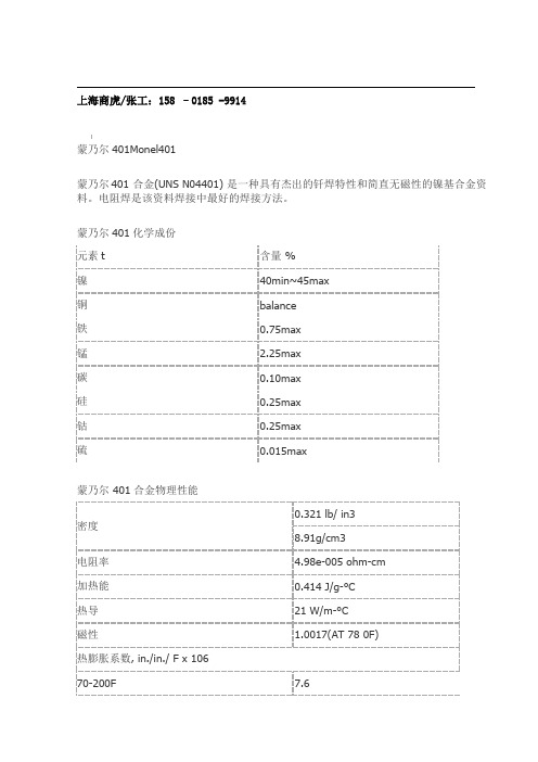
上海商虎/张工:158 –0185 -9914蒙乃尔401Monel401蒙乃尔401 合金(UNS N04401) 是一种具有杰出的钎焊特性和简直无磁性的镍基合金资料。
电阻焊是该资料焊接中最好的焊接方法。
蒙乃尔401化学成份蒙乃尔 401合金物理性能特性:蒙乃尔401是一个非常低的电阻温度系数和中程电阻率的合金。
它主要用于专业电气和电子应用程序。
应用:线绕精密电阻和枚双金属触摸.产品:哈氏合金、高温合金、铜镍合金、英科耐尔、蒙乃尔、钛合金、沉淀硬化钢等各种中高端不锈钢,镍基合金等。
高温合金:GH3030、GH4169、GH3128、GH145、GH3039、GH3044、GH4099、GH605、GH5188等软磁合金:1J06、1J12、1J22、1J27、1J30、1J36、1J50、1J79、1J85等弹性合金:3J01、3J09、3J21、3J35等。
蒙乃尔合金:Monel 400(N04400)、Monel K500(N05500)等膨胀合金:4J28、4J29(与玻璃烧结)、4J32、4J33、4J34、4J36、(与陶瓷烧结)4J38、4J42、4J50等耐蚀合金:Inconel 600、601、617、625、686、690、713C、718、Inconel X-750等因科洛伊合金:Incoloy 20、330、718、800、800H、800HT、825、925、Inconel 926【N08926/1.4529】等哈氏合金:Hastelloy C、C-4、C-22(N06022)、C-276、C-2000、Hastelloy B、B-2、B-3等纯镍 / 钛合金:N4、N5(N02201)N6、N7(N02200)TA1、TA2、TA9、TA10、TC4等沉淀硬化钢/双相不锈钢17-4PH(sus630)、17-7PH(sus631)、15-5PH/ 2205、2507、904L、254SMO、20#(N08020)生产工艺:热轧、锻轧、精扎、机轧、挤压、连铸、冷拔、浇铸、冷拉等供应规格:棒材、板材、管材、带材、毛细管、丝材及块料。
Dual N-Channel JFET Switch
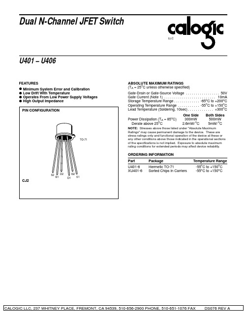
CJ2
CALOGIC LLC, 237 WHITNEY PLACE, FREMONT, CA 94539, 510-656-2900 PHONE, 510-651-1076 FAX
DS076 REV A
U401 – U406
LLC
ELECTRICAL CHARACTERISTICS (TA = 25oC unless otherwise specified)
BVG1-G2
±50
±50
±50
±50
±50
±50
gfs
2000 7000 2000 7000
2000
7000
2000
7000
2000
7000
2000
7000
VDS = 10V, VGS = 0
f = 1kHz
gos
20
20
20
20
20
20
µS
gfs
1000 2000 1000 2000
1000
2000
SYMBOL PARAMETER Gate-Source Breakdown Voltage Gate Reverse Current (Note 2) Gate-Source Cutoff Voltage Gate-Source Voltage (on) Saturation Drain Current (Note 3) Operating Gate Current (Note 2) Gate-Gate Breakdown Voltage Common-Source Forward Transconductance (Note 3) Common-Source Output Conductance Common-Source Forward Transconductance Common-Source Output Conductance Common-Source Input Capacitance (Note 6) Common-Source Reverse Transfer Capacitance (Note 6) Equivalent Short-Circuit Input Noise Voltage Common-Mode Rejection Ratio Differential Gate-Source Voltage Gate-Source Voltage Differential Drift (Note 4) 95 5 0.5 -.5 U401 MIN BVGSS IGSS VGS(off) VGS(on) IDSS IG -50 -25 -2.5 -2.3 10.0 -15 -10 0.5 -.5 MAX U402 MIN -50 -25 -2.5 -2.3 10.0 -15 -10 0.5 -.5 MAX U403 MIN -50 -25 -2.5 -2.3 10.0 -15 -10 0.5 -.5 MAX U404 MIN -50 -25 -2.5 -2.3 10.0 -15 -10 0.5 -.5 MAX U405 MIN -50 -25 -2.5 -2.3 10.0 -15 -10 0.5 -.5 MAX U406 MIN -50 -25 -2.5 V -2.3 10.0 -15 -10 mA pA nA V VDG = 15V, ID = 200µA VDS = 10V, VGS = 0 VDG = 15V, ID = 200µA TA = 125oC VDS = 0, V GS = 0, IG = ±1µA MAX V pA VDS = 0, IG = -1µA VDS = 0, V GS = -30V VDS = 15V, ID = 1nA UNITS TEST CONDITIONS
monel 401合金铜含量
一、概述Monel 401合金是一种具有优异性能的铜镍合金,其中铜是合金的重要组成成分之一。
本文将重点讨论Monel 401合金中的铜含量及其对合金性能的影响。
二、Monel 401合金的铜含量Monel 401合金是一种含有大量镍和少量铜的合金。
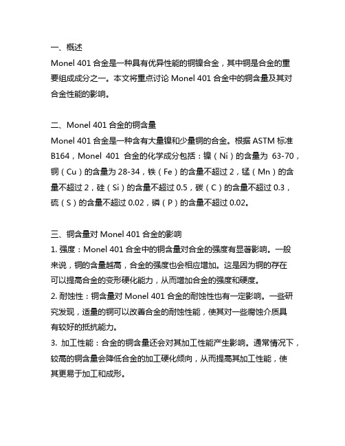
根据ASTM标准B164,Monel 401合金的化学成分包括:镍(Ni)的含量为63-70,铜(Cu)的含量为28-34,铁(Fe)的含量不超过2,锰(Mn)的含量不超过2,硅(Si)的含量不超过0.5,碳(C)的含量不超过0.3,硫(S)的含量不超过0.02,磷(P)的含量不超过0.02。
三、铜含量对Monel 401合金的影响1. 强度:Monel 401合金中的铜含量对合金的强度有显著影响。
一般来说,铜的含量越高,合金的强度也会相应增加。
这是因为铜的存在可以提高合金的变形硬化能力,从而增加合金的强度和硬度。
2. 耐蚀性:铜含量对Monel 401合金的耐蚀性也有一定影响。
一些研究发现,适量的铜可以改善合金的耐蚀性能,使其对一些腐蚀介质具有较好的抵抗能力。
3. 加工性能:合金的铜含量还会对其加工性能产生影响。
通常情况下,较高的铜含量会降低合金的加工硬化倾向,从而提高其加工性能,使其更易于加工和成形。
四、铜含量对Monel 401合金性能的优化针对上述影响,可以通过控制Monel 401合金中的铜含量来优化合金的性能。
具体而言,可以通过以下方式实现:1. 调整合金配方:通过调整合金中的铜含量,以获得期望的强度、耐蚀性和加工性能。
在实际生产中,可以通过合金配方设计来实现对含铜量的精确控制。
2. 精细化合金组织:通过合适的热处理和热加工工艺,可以实现对Monel 401合金组织的精细化调控,从而进一步优化合金的性能。
五、结论Monel 401合金中的铜含量对其性能具有重要影响,可以通过合适的铜含量控制和优化来实现对合金性能的调节。
今后的研究和生产中,应该充分考虑铜含量对合金性能的影响,以实现合金性能的最佳平衡。
牛津译林版英语九上9A U401

9A U401课题:Welcome to the unit【重点单词】on one’s mind time whenever through as soon as deala great deal of【重点词句】1.你在惦记什么?What’s on your mind?2.成长的过程是很困难的。
Growing up is hard.3.怎么了?What’s up?4.自从我一开始遇见你,你就很开心。
You’ve been happy since I first met you.5.对于我的屋子来说,我已经长的太大了。
I’m growing too big for my house.6.给你自己另造一个房子。
Build another one for yourself.7.直到你造好房子再叫醒我吧。
Don’t wake me up until you finish building it.8.你为什么喜欢通过那种方式学?Why do you like to learn that way?9.允许我学习不同时期和不同地方的人allow me to learn about people in differenttimes and places10.无论何时我想读他们read them whenever I want to11.凭借网络through the Internet12.你一点击鼠标,就会有大量的信息。
As soon as you click the mouse, there’s a greatdeal of information.【知识梳理】1.not … until …直到……才……(引导时间状语从句,从句不能用将来时)主句是一般将来时,从句用现在时例如:我直到他回来才离开。
I will not leave until he comes back.主句是祈使句,从句用现在时例如:直到公交车停了才下车。
长虹液晶彩电常见开关电源维修资料

长虹液晶彩电常见开关电源维修资料长虹液晶彩电HS210-4N02-2开关电源维修资料长虹液晶彩色电视采用HS210-4NO2-2电源板,该电源板可直接代换长虹GP09,HS210-4N10,FSP205-3E01C电源板,对+12V输出电路稍加改动,可以代换GP02,FSP205-4EOIC,FSP179-4F01电源板。
长虹HS280-4NO1,HS280-4NO2,HS308-4NO1,HS368-4NO1的主电源均采用NCP1395,NCP5181系列集成电路,均可参照本节维修。
HS210-4NO2-2电源板由三部分组成:一是由NCP1014P100(U1)和变压器T1组成的副开关电源,为微处理器控制系统提供+5.4VS电压;二是由NCP1606BDR2G(U2)和变压器T3组成的PFC 电路,为主开关电源提供+380V电压;三是由NCP1395DR2G (U4),NCP5181DR2G(U3)和变压器TZ组成的主开关电源,向负载主板和背光灯板电路提供24V和12V,5.25V电压。
开关机采用控制PFC电路和主开关电源的VCC1供电的方式,开机后以NCP1014P100为核心的副电源首先工作,输出两种电压:一是为主板控制系统提供5.4VS电压,控制系统工作后为电源板送入开机STB控制电压,二是副电源输出VCC电压,经开关机电路控制后,为PFC驱动电路NCP1606BDR2G和主电源驱动电路NCP1395DR2G 提供VCC1工作电压,PFC电路和主电源电路启动工作,市电整流滤波后VA约300V经PFC电路校正后,提升到约380V,产生VB电压,为主电源供电。
主电源工作后,为主电路板和背光灯逆变器板提供5.25V,12V和24V电源,整机进入开机收看状态。
长虹液晶彩色电视HS210-4NO2-2电源板在主开关电源输出端设有24V,12V,5.25V过电压保护和5.25V过电流保护电路,保护电路启动时,迫使开关电源停止工作。
RJMU401国密安全芯片数据手册说明书

⏹封装功能 大容量增强型,基于ARM 安全智能卡内核的国密安全芯片内嵌SM1、SM2、SM3、SM4国密加密算法RJMU401数据手册⏹内核:高性能32位ARM SC100 CPU — 双总线架构,DMA 加速,快速中断响应— 支持ARM 和Thumb 指令集— 三级流水线— 采用软内核技术,防止外部对其进行扫描 — 采用小端存储格式— 主频为32MHz ,可进行3、4分频,系统默认工作频率8M ⏹存储器— 8KB ROM— 18K RAM— 128~550KB 的FLASH 存储器⏹时钟、复位和电源管理— 1.6V~5.5V 供电— CPU 时钟可由软件配置为内部时钟— 内置32 MHz 高速RC 振荡器,支持3/4分频 — 内置多功能时钟发生电路— 内置32 KHz 低功耗RC 振荡器 ⏹多达6个定时器— 3个16位通用定时器、— 1个ETU 定时器— 1个Wake-up 定时器— 1个32位看门狗定时器⏹多种密码算法— 对称算法:DES 、T-DES 、AES 、SM1、SM4— 非对称算法:RSA 、SM2— 摘要算法:SM3、SHA-256⏹安全特性— 存储保护单元(MPU )— 频率检测功能— 存储总线检测功能,防FIA 攻击 — 抗EMA/DEMA 攻击 — 硬件CRC16/32电路校验 — 硬件真随机发生器 — 防篡改检测电路 ⏹外围接口— 1路智能卡接口,符合ISO7816标准,支持T=0/T=1协议— 1路SWP 接口,速率高达1.2Mbps — 1路SPI 主从接口— 1路UART 接口— 高达15路GPIO ,支持多种中断方式,多达12路GPIO 可复用 ⏹应用市场— 城市一卡通PBOC 终端、一卡通、银行POS 机、移动无线支付等金融支付— SIM 卡、JA VA 卡、ESIM 卡等领域 — 嵌入式软件安全保护— 手机、通信模块、路由器、对讲机等数据加密 — 监控设备、自动化控制 VSOP8LSSOP20L1.1概述 (3)1.2系统架构 (4)2、性能参数 (6)2.1处理器系统 (6)2.2存储单元 (6)2.3中断控制器 (7)2.4时钟与定时器 (7)2.5安全性及物理防护 (8)2.6对外接口 (10)2.7算法性能 (11)2.8模块功耗性能 (12)2.9其他模块 (14)2.10模拟模块 (14)3、引脚定义 (15)3.1引脚定义图:SSOP_20L (15)3.2引脚定义图:VSOP_8L (16)4、接口电气特性 (17)4.1测试条件 (17)4.1.1 最小和最大数值 (17)4.1.2 典型数值 (17)4.27816接口电气特性 (17)4.2.1绝对最大额定值 (18)4.3SPI接口电气参数 (18)4.3.1绝对最大额定值 (19)5、电源模块设计及工作条件 (21)5.1电源电路模块设计 (21)5.2推荐工作参数 (22)6 、SPI功能描述 (23)6.1概述 (23)6.2时钟信号的相位和极性 (23)7、应用电路图 (25)7.1RJMU401FHO与STM32F103的7816参考电路 (25)7.2RJMU401FHO的SPI参考电路 (25)7.3RJMU401EHV与STM32F103的7816参考电路 (26)8、电气特性 (27)9、芯片封装信息 (28)10、订货信息 (30)附录一:简称及缩略语 (32)1、简介1.1 概述RJMU401安全芯片是一个基于32位RISC处理器的SOC芯片,具备高处理能力、高安全性、低功耗、低成本等特点。
UE Systems Ultraprobe 401 Grease Caddy Manual

UE SYSTEMSTHE ULTRAPROBE 401GREASE CADDY MANUALTABLE OF CONTENTSOVERVIEWMOUNTING AND SETUPUSERS INSTRUCTIONS Basic Components Main Unit Grease Gun Mounting Kit Mounting the Digital Grease Caddy on a Grease GunSetup Completed AssemblyGetting StartedDisplay Panel Screens and Functions Moving Around the ScreensFunction BarChanging Display Screens Storing A Record Display Screens 1,2 SD InfoSetup Menu Screens01 Add/Remove SD Card 02 Store Before/After 03 Add Lube Amount 04 Instrument Setup 05 Default Settings06 User Sensitivity Default 07 User Frequency Default 08 Frequency Adjust 09 Display Response 10 Headphone Volume 11 Enter Inspector Id 12 Set Time and Date 13 Date Format 14 Cal Due Date15 Db Scale Type Select 16 Db Offset Value3 34 45 5 5 56 6 67 7 78 89 9 9 9 10,1110 11 11 11 12 12 12 13 13 13 14 14OTHER FEATURES SPECIFICATIONS17 Battery Level18 System ShutdownSelecting SensitivityChanging Storage Record NumberRecording the Amount of Lubricant Added14141415151617OVERVIEWThe 401 Digital Grease Caddy Pro is an important element to ultrasound assisted lubrication. Through uploading and downloading of bearing data it lets users know when to stop adding lubrication as well as provide data of lubrication history that adds to analysis of bearing condition to prevent premature failure.BASIC COMPONENTS OF THE UP401 GREASE CADDY KITUltraprobe 401 Digital “Grease Caddy” Mount BallGrease Gun Docking PlateMagnetic Transducer (RMT)Clamp to Grease Gun ChargerHeadphones Adjustable Ball MountHolster with Belt ClipMAIN UNITGREASE GUN MOUNTING KITDisplay PanelSensitivity/Spin and Click dialOn/Off Button Headphone jackSD Card SlotLED Flash LightBNC RMT PortRecharge JackMountGrease Gun Mount FootClamp Knob Open clamp EndMount BallGrease Gun Ring with foam stripMOUNTING AND SETUPMOUNTING THE 401 DIGITAL GREASE CADDY TO GREASE GUNScrew Mount Ball into threaded fitting on the bottom of the Digital Grease Caddy housingas shown.Place Mount on Grease gun so that the Grease Gun Mount Foot (15) is resting on thegrease gun.Place Grease Gun Ring with foam strip around the Grease Gun and over the Mount foot.Tighten the Grease Gun Ring until the mount is firmly in place.Attach the Digital Grease Caddy by placing the Gun Mount Ball in the open clamp end.Tighten the clamp knob.SETUPAttach the 401 Digital Grease Caddy mount to the grease gun as described above.Attach the Magnetic Mount transducer cable to BNC connector.Plug in the Headphones to the Headphone jack.COMPLETED ASSEMBLYUSERS INSTRUCTIONSGETTING STARTEDOn/Off Button: Press the On/Off button to turn the instrument on. To turn off press andhold the button again.Sensitivity/Spin and Click dial: Use this dial to store data, move around the various screensand to setup the instrument (See Section B-1: Moving around the screens using theSensitivity/Spin & Click dial).The SD card slot: Lift the cover and insert the SD card. The card must be inserted to storedata and to review baseline data.The charging jack: Location to insert the recharger plug. A green light will blink as the unitis charging a solid green will indicate a full charge.BNC Connect: Be sure the magnetic mount transducer is attached via the BNC connectorbefore any lubricating is performed.Before operating, be sure the magnetic transducer is attached to the docking station andthe docking station is mounted on the end of grease gun tube as shown above. DISPLAY PANEL SCREENS AND FUNCTIONSTo move around a screen or to enter and use a feature of the “Function Bar” (described below) there are two ways to use the Sensitivity/Spin and Click dial.Lightly click to move the blinking indicator/cursor to a feature on the display screen. Forexample, to adjust the sensitivity, click the Sensitivity dial until the S= blinks. Spin the Sensitivity dial clockwise (UP) or counterclockwise (DOWN) to adjust the sensitivity.The second method is to push and firmly hold the Sensitivity/Spin & Click dial. This is used to store a reading or enter any of the Function Bar features.FUNCTION BARThe “Function Bar” is located on the bottom of each Displayscreen (Display Screen 1 and Display Screen 2).There are 4 selections:SD INFO, Display 1, Display 2, Setup Menu, STORErecord.TO ENTER AND USE THESE FUNCTIONSClick the Sensitivity dial until the Function Bar blinks.Locate the desired Function menu by spinning the Sensitivity Dial.Push and briefly hold the Sensitivity Dial to select and enter the Function.TO CHANGE DISPLAY SCREENSClick the Sensitivity dial until the Function Bar blinks.If the Display screen is not shown, spin the Sensitivity dial until it is visible.Push and hold the Sensitivity Dial while noting the screen change.TO STORE A RECORDThe STORE Record prompt is located on the Function bar of both Display 1 and Display 2.If STORE Record is not shown, click the Sensitivity dial until the cursor blinks on theFunction Bar and spin the Sensitivity dial until STORE Record is displayedTo store a record, push and briefly hold the Sensitivity dial. The screen will display “STORE R ECORD CONFIRMED” and move to the next storage locationFunction BarTHERE ARE FOUR SCREENS: TWO DISPLAY SCREENS AND TWO “FUNCTION BAR” SCREENSDISPLAY SCREEN 1Displays: Sensitivity value “S =” record location (001- 400), dB level and the “Function Bar” on the bottom of the screen DISPLAY SCREEN 2Displays: Sensitivity value “S =” record location (001- 400), dB level along with a bar graph intensity indicator and the “Function Bar” on the bot tom of the screenSD INFO (FUNCTION BAR SCREEN). Contains SD card information;Spin to a feature, click to use:Delete all files (Click to enter, spin to “yes”)Free space and info (Click to enter)Display filesTo exit push and briefly hold the Sensitivity dialThis is Display 2 showing the ability to move to Display 1shown in the Function bar.This is Display 1 showing the ability to move to Display 2shown in the Function bar.SETUP SCREENSSETUP MENU (FUNCTION BAR SCREEN). There are 18 Setup menus. To enter and use the setup menus:Click the Sensitivity dial until the cursor blinks on the Function Bar.If Setup menu is not shown, spin the Sensitivity dial until Setup menu appears. Push andhold the Sensitivity dial until the first screen appears. To move to a specific setup item, spin the Sensitivity dial to the setup menu number (1-18). Push and hold to enter and use. SETUP MENU SCREENSMENU 01 ADD/REMOVE SD CARDBe sure to insert the SD card before turning the Ultraprobe on.The Group data will be read by the Ultraprobe on power up.On power down (off), all data and WAV files are stored on the SD card.The Add/Remove SD Card function allows users to change the card while the unit is on.While the power is on, a warning will advise againstremoval (unless Menu 01 is selected).NOTE: There is a risk of losing data if the SD card is removedwithout activating Menu 01. The SD card must be inserted intothe Grease Caddy to review and store data.MENU 02 STORE BEFORE/AFTER. When selected, this function allows the user to store decibel readings before adding lubricant and after adding lubricant.To set this function:Enter set up mode and go to Menu 02.Click the Sensitivity dial to select and spin it to "ON”.Then click the Sensitivity dial to set.To exit press and hold the sensitivity dial.MENU 03 ADD LUBE AMOUNT. The number of strokes ofthe grease gun used to apply the grease can be added afterthe lubricant has been applied and Add Lube Amount has beenselected.To select this feature:Enter set up mode and go to Menu 03Click the Sensitivity dial to select and spin it to "ON”Click the Sensitivity dial to setTo exit press and hold the Sensitivity dialMENU 04 INSTRUMENT SET-UP. The factory default is “MANUAL”. All adjustments are made by the inspector while going throug h the route. The “AUTOMATIC” setting is used after the initial baseline data has been uploaded to the Ultraprobe 401. In the Automatic setting, the instrument will move sequentially from one test point to the next, and set itself for the original baseline setup, which will include the Frequency and Sensitivity for that point.FOR EXAMPLE: If the operator is testing bearings, the instrument will move from test point 1 to test point 2 and the if the baseline data was set at a sensitivity level of 43 with a frequency of 30 kHz, the instrument will automatically set for these parameters.To change this setting:Enter set up mode and go to Menu 04Click the Sensitivity dial to select. The selections are“MANUAL” and “AUTO”Spin to select, click to setTo exit, press and hold the Sensitivity dialMENU 05 DEFAULT SETTINGSTo change this setting:Enter set up mode and go to Menu 05.Click the Sensitivity dial to select. The selections are “YES”and “NO”.Spin to select, click to set.To exit, press and hold the Sensitivity dial.MENU 06 USER SENS.(SENSITIVITY) DFT (DEFAULT)To change this setting:Enter set up mode and go to Menu 06.Click the Sensitivity dial to select. The default value is 70.Spin to the desired value, click to set.To exit, press and hold the Sensitivity dial.MENU 07 USER FREQ.(FREQUENCY) DFT (DEFAULT)To change this setting:Enter set up mode and go to Menu 07.Click the Sensitivity dial to select. The frequency range is 20 kHz to 100 kHz.Spin to the desired frequency value, click to set.To exit, press and hold the Sensitivity dial.MENU 08 FREQUENCY ADJUST. This feature allows the user to change frequencies between 20 kHz and 100 kHz in one kHz intervals.To change this setting:Enter set up mode and go to Menu 08.Click the Sensitivity dial to select. The frequency range is 20 kHz to 100 kHz.Spin to the desired frequency value, click to set.To exit, press and hold the Sensitivity dial.MENU 09 DISPLAY RESPONSE. This setting will affect the movement of the intensity indicator.To change this setting:Enter set up mode and go to Menu 09.Click the Sensitivity dial to select. It may be set forSLOW, MEDIUM or FAST.Spin to the desired speed, click to set.To exit, press and hold the Sensitivity dial.MENU 10 HEADPHONE VOLUME. This feature allowsfor adjustments to the sound level or volume level in theheadphone. Click to enter the volume selections range from0% to 99%. The default value is 95%.MENU 11 SET INSPECTOR IDTo enter an ID:Enter set up mode and go to Menu 11.Click the Sensitivity dial to select. There are threealphanumeric spaces.Spin to the desired number or letter, click to set. Follow onscreen instructions.To exit, press and hold the Sensitivity dial.MENU 12 SET TIME & DATETo set the time and date:Enter set up mode and go to Menu 12.Click the Sensitivity dial to select.Use Sensitivity dial to set the time and date.To exit, spin to select “EXIT” which will blink and click to exit.MENU 13 SET DATE FORMAT. This allows forchanges to the value from month/day/year today/month/year.To set the date format:Enter set up mode and go to Menu 13.Click the Sensitivity dial to select.Use Sensitivity dial to choose date format.To exit, click the Sensitivity dial.MENU 14 CAL(CALIBRATION) DUE. The due date for instrumentcalibration is shown on the screen.MENU 15 DB SCALE TYPE. The choices are “Relative” and“Offset”.To change this setting:Enter set up mode and go to Menu 15.Click the Sensitivity dial to select.Use Sensitivity dial to choose between “Relative” andOffset”.To exit, click the Sensitivity dial.MENU 16 DB OFFSET VALUETo set the offset value:Enter set up mode and go to Menu 16.Click the Sensitivity dial to select.Use Sensitivity dial. Turn left for the values -1 thru -10.And spin right for values 1 thru 40.To exit, click the Sensitivity dial.MENU 17 BATTERY LEVEL.Click to see battery charge level.MENU 18 SYSTEM SHUTDOWN. Select “System Shutdown” and click the Sensitivity dial to shut off the UP401.OTHER FEATURESSELECTING SENSITIVITY. The sensitivity is displayed on both Display Screen 1 and 2 as “S=.” The highest sensitivity value is 70, the lowest is 0. To adjust the sensitivity value, the “S=” must blink on the display screen.If it is not blinking:Click and release the Sensitivity dial and observe which feature is blinking. Keep clickinguntil the “S=” blinks.Spin the Sensitivity dial to the right (clockwise) to increase the sensitivity value or to theleft (counter clockwise) to decrease it.CHANGING STORAGE RECORD NUMBERTo change the storage location before storing a reading:Click around the screen using the Sensitivity dial until therecord number in the upper right corner blinks.Spin the Sensitivity dial to the preferred record number.Click firmly to set; the cursor will move to the functionbar.If Store Record is showing on the function bar press to store.If store record is not showing spin until it does show. Then press the Sensitivity dial to store.To view data stored in a record number:Click to the function bar and spin until Display 1 is shown.Press the Sensitivity dial to select Display 1.Click the Sensitivity dial until the record number in theupper right corner blanksSpin the Sensitivity dial either left or right to view therecord. The decibels will be shown in the middle right ofthe screen.TO RECORD THE AMOUNT OF LUBRICANT ADDED. There are two methods that allow for the user to enter the number of pumps of lubrication to be recorded. The first, is without the “Store Before and Store After” function enabled. The other is with the “Store Before and Store After” function enabled .Using the feature Without the “Store Befo re andAfter” function enabled: be sure “Add Lube Amount” isselected in the set-up menu.After adjusting the sensitivity to obtain the proper DBreading, click the Sensitivity dial until the 00 is blinking inthe function bar.Then add lubricant and record the number of strokes used by clicking the power button.Each click will equal one stroke.When through press and hold the Sensitivity dial to store the record.Using the feature With the “Store Before and After” function enabled .Record numberdB shown hereTo use this feature, go to set up men u and select “AddLube Amount.”Store the decibel reading before adding lubricant. Thiswill be in the store before record shown in the function bar.Then add lubricant and record the number of strokesused by clicking the power button. Each click will equal one stroke.When finished, press and hold the Sensitivity dial to storethe record.Need further support?Want information regarding products or training?CONTACT:UE Systems Europe B.V. – Windmolen 20, 7609NN Almelo, The NetherlandsT: +31-546 725 125 | E:*****************|W: www.uesystems.euHOUSINGCONSTRUCTIONDIMENSIONSCIRCUITRYMEMORYOUTPUTSTRANSDUCERHEADSETFREQUENCYRESPONSERESPONSE TIMEDISPLAYOPERATINGTEMPERATURERELATIVE HUMIDITYINDICATORSATTACHMENTPOWERWEIGHTWARRANTY Attaches directly to the grease gun, gives visual and audible indication for proper lubrication PC + ABS Plastic 7.0”x3.2”x3.0” :::: 17/8x8.1x7.6 cm (LWH) Solid State Analog and SMD Digital Circuitry with temperature compensation and true RMS conversion 400 Storage locations Calibrated heterodyned output, decibel (dB) Magnetically Mounted Piezoelectric transducer Deluxe noise isolating headset for hard hat use Over 23 dB of noise attenuation. Meets or exceeds ANSI Specifications and OSHA standards Peak response: centered around 38 kHz <10 ms 128x64 LCD with LED backlight 32o F to 122o F :::: 0o to 50o C 10-95% non-condensing at up to 86o F :::: 30o C dB, Battery Status and 16 Segment Bar Graph Universal: fits most commercially used cartridge grease guns Lithium Polymer rechargeable 1.25 Lbs. :: .57 kg5-year parts/labor standard SPECIFICATIONS Covered by one or more of the following patents: 0151115,0303776,0315199,1206586,1297576,1881263,2562758,2689339, 4416145, 4823600,5955670,6122966, 6339961, 6341518, 6415645, 6655214, 6707762, 6804992. UE Systems is committed to continual product improvement: therefore specifications are subject to change without notice. Warranty details are available by request.。
UM401NR资料
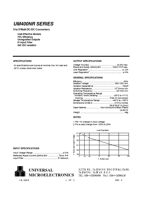
GENERAL SPECIFICATIONS
Efficiency … … … .… … … … … … … .… … … ..… .… … .… … 50% Isolation Voltage … … … … … … … … … … … … . 500 VDC min. Isolation Capacitance … … … … … … … … … … … … ..… 180pF 8 Isolation Resistance … … ..… … … … … ..… … . 10 Ohms min. Switching Frequency … … … .… … … … … ...… … 50 KHz min. Operating Temperature Range Ambient, None Derating … … … … … .… … -25°C to +71°C Cooling … .… … … … … … .… … … … … Free Air Convection Storage Temperature Range … … … … .… . –40°C to +100°C Dimensions CASE C … .… … … … … … ...… … 2*2*0.4 inches (50.8*50.8*10.2mm) Case Material ,… .… … … … … Non-Conductive Black Plastic UL94V-0 Weight … … ..… … … … … … … … … … … … … … … … … … . 46g
All specifications are typical at nominal line, full load and 25°C unless otherwise noted.
ue410安全继电器说明书
ue410安全继电器说明书一、产品概述UE410安全继电器是一种集成了多种安全功能的继电器,主要用于工业自动化控制系统中,提供安全可靠的电气控制。
该继电器符合国际安全标准,具备多种保护功能,能够有效防止设备损坏和人员伤害。
二、主要功能特点1.多种保护功能:UE410安全继电器具备过流保护、短路保护、欠压保护等多种保护功能,能够有效地保护电气设备的安全。
2.符合国际安全标准:UE410安全继电器符合国际安全标准,如EN60947、UL508等,确保在各种应用场景下的安全可靠性。
3.易于配置:UE410安全继电器支持多种输入和输出接口,可以根据实际需求进行灵活配置,方便用户使用。
4.智能化控制:UE410安全继电器内置智能控制芯片,可以实现自动控制和远程控制,提高了设备的自动化水平。
5.高可靠性:UE410安全继电器采用优质材料和先进工艺制造而成,具有高可靠性和长寿命,能够保证长期稳定运行。
三、使用说明1.安装与接线:按照产品手册中的安装说明,正确安装UE410安全继电器,并按照电路图进行接线。
确保接线牢固可靠,避免出现接触不良等问题。
2.参数设置:根据实际需求,通过控制面板或编程软件对UE410安全继电器的参数进行设置,包括保护功能、动作阈值、输出类型等。
请参考产品手册了解详细的参数设置方法。
3.运行与调试:在完成安装和参数设置后,接通电源,启动UE410安全继电器进行运行和调试。
观察设备的运行状态,确保各项功能正常工作。
4.维护与保养:定期对UE410安全继电器进行检查和维护,保持设备的良好运行状态。
如发现异常情况或故障,请及时联系专业人员进行检修和保养。
四、注意事项1.使用前请仔细阅读本说明书,了解UE410安全继电器的各项功能和操作方法。
如有疑问,请及时咨询专业技术人员。
2.在使用过程中,请遵循相关电气安全规范和标准,确保设备和人员的安全。
3.请勿随意拆卸或改装UE410安全继电器,以免造成设备损坏或安全隐患。
DL401中文资料
Manual D L401DL401100 MHz FADC1. Funktion (2)1.1. Übersicht (2)1.1.1. Anwendung (2)1.1.2. Daten (2)1.1.3. Besonderheiten (2)1.1.4. Aufbau (2)1.1.5. Stromversorgung (2)1.2. Blockdiagramm (3)1.3. Funktionsbeschreibung (3)1.4. Steckerbelegungen (4)1.4.1. P1-VME (4)1.4.2. P2-VME32/VXI (4)1.4.3. DL400C (5)2. Betrieb (6)2.1. Konfigurierung (6)2.1.1. Jumper (6)2.1.2. SHORT-Adresse (6)2.1.3. Interne/Externe Clock (6)2.1.4. Lineare/Nichtlineare Kennlinie (6)2.2. Bedienung (7)2.2.1. Eingangssignale (7)2.2.2. Steuerung (7)2.3. Programmierung (8)2.3.1. Reset (8)2.3.2. Initialisierung (8)2.3.3. Speicheraufteilung (9)2.3.4. Speicheraufteilung DL401Z (9)2.3.5. Serial DAC Programmierung (9)1. F UNKTION1.1. Übersicht1.1.1. AnwendungDriftkammern, Transient Recording1.1.2. DatenParameter WertKanalzahl4Abtastrate / Kanal≤ 100 MHz Speichertiefe1024 Samples Amplitudenauflösung linear8 BitAmplitudenauflösung nichtlinear10 BitEingangsempfindlichkeit (im unteren Bereich)195 µV/LSB Verstärkung (Anpaßverstärker)10Pedestal Korrektur 6 Bit1.1.3. Besonderheiten-COMMONSTART-COMMONSTOP, Addresscounter lesbar-AUTOSTOP bei Memory Overflow-START und STOP per Software-RUN und EOC (EndOfConversion) per Software lesbar-Multiple Event Speicherung-Auslese wahlfrei-100 MHz Quartzclock wahlweise1.1.4. AufbauDL400 Application-Module, VME-Doppeleuropa, Breite 3TE, Höhe 6HE1.1.5. StromversorgungSpannung Strom Leistung+5V.45 A 2.15 W-5.2V 4.6 A24 W+12V0.125 A 1.5 W-12V25 mA.3 WGesamt28.05 W1.2. Blockdiagramm1.3. FunktionsbeschreibungVon einem Frontstecker werden die differentiellen Analogsignale von 4 Kanälen über Anpaßverstärker um den Faktor 10 verstärkt und können für eine optimale Ausnutzung desdynamischen Bereichs im Pedestal verschoben werden. Die Pedestalwerte werden für alle Kanäle unabhängig in einem 4 Kanal DAC mit 6 Bit Auflösung erzeugt.Die Amplitudenauflösung der nachfolgenden FADCs beträgt 8 Bits. Durch ein vorgeschaltetes Netzwerk (NL) kann der dynamische Bereich um den Faktor 4 erweitert werden, so daß eine nichtlineare Übertragungsfunktion mit einer effektiven Amplitudenauflösung von 10 Bits (im unteren Bereich) erreicht wird.Das GATE-Signal über einen Frontstecker, bzw. über Software gesetzt, bestimmt Beginn und Ende der Aufzeichnung. Auf jeden CONVERT-Impuls werden die momentanen Analogwerte an allen 4 Kanälen gleichzeitig digitalisiert und anschließend in die Speicher eingeschrieben. Der Impuls kann wiederum von der Frontplatte oder per Software generiert werden. Als Quelle kann auch ein 100 MHz Quartzoszillator auf dem Board verwendet werden.Nach dem Einschreiben wird der Adresszähler um 1 erhöht. In der Betriebsart 'AutoStop' wird bei einem Überlauf des Zählers (>1023) die Aufzeichnung gestoppt, im anderen Modus(CommonStop) beginnt die Aufzeichnung immer wieder bei 0!Die Digitalisierung wird normalerweise durch Wegnahme des GATE-Signals beendet. Zu diesem Zeitpunkt wird ein Bit gesetzt und das Modul generiert (falls ermöglicht) einen Interrupt.Der Addresscounter wird dann gegebenenfalls ausgelesen und das wahlfreie Auslesen der Daten kann erfolgen.Falls die Tiefe der Memories dies erlaubt kann nach einem Stop auch die Wiederaufnahme der Aufzeichnung ohne Zwischenauslese erfolgen (Multi event storage). Bei einem RESET wird der Addresscounter auf 0 gesetzt.1.4. Steckerbelegungen1.4.1. P1-VME1.4.2. P2-VME32/VXI1.4.3. DL400C2. B ETRIEB2.1. Konfigurierung2.1.1. JumperBetriebsart Jumper BemerkungInternal Clock J3,/J4Quartz ClockExternal Clock J4,/J3NIM-InputDelay Delay do not changeDebug J1, J2do not change2.1.2. SHORT-AdresseUm das Modul im SHORT-Adressraum von VME ansprechen zu können, muß die gewünschte Adresse des Moduls mit den Rotary-HEX-Schaltern auf der DL400 Basisplatine eingestellt werden (siehe weiter unter 2.3. Programmierung).2.1.3. Interne/Externe ClockFalls die interne Clock mit 100 MHz benutzt werden soll, muß Internal Clock gesetzt werden.2.1.4. Nichtlineare/Lineare KennlinieBei nichtlinearer Eingangsbeschaltung der FADCs ist der Zusammenhang zwischen dem FADC-Code (C) und der Eingangsspannung (U i) am Modul nach folgender Formel gegeben:U i =C256 - a * C * U o / K;K (=10) kennzeichnet die Verstärkung des Anpaßverstärkers.a (=0.75) ist der Expansionsfaktor.U o (=0.5V) ist die Referenzspannung bei U i =0;ACHTUNG: Bei linearer Eingangsbeschaltung des FADC müssen die Widerstände R79…R82 (=15.4 Ω) unter den FADC chips entfernt werden (a=0, U o = 2V).2.2. Bedienung2.2.1. EingangssignaleDie analogen Signale für 4 Kanäle werden als differentielle Signale von der Frontseite zugeführt. Die Eingangsimpedanz zwischen den Eingangspins ±Cn beträgt 100Ω. Die Spannung für Vollaussteuerung beträgt 160mV.2.2.2. SteuerungZur externen Steuerung dienen im wesentlichen die 2 NIM-Signale GATE und CONVERT:•CONVERT: Dieses Signal stellt die Clock für die Konvertierung dar.•GATE: Dieses Signal bestimmt die Dauer der Konvertierung.2.3. Programmierung über DL400Das Modul ist ohne Programmierung zunächst nur im Short-Addressbereich (AM=$2D oder $29) ansprechbar. Die Bezeichnung "ss" in den folgenden Adressangaben steht für dieEinstellung der HEX-Schalter!2.3.1. ResetWRITE:SHORT.$ss20RESETD31D15D0HighWord LowWordLongWord2.3.2. InitialisierungFür die Festlegung der Standard-Basisadresse des Moduls, der Modulgröße, der gewünschten Addressmodifier und der Parameter für einen Interrupt müssen verschiedene Register (im Short-bereich) auf der DL400 Basisplatine geladen werden!WRITE:SHORT.$ss50D0…D15: Address Std-BaseaddressSHORT.$ss60D0…D3: MaskD8…D13: AMD15: Enable Mask for Submodule Size Address Modifierenable STD-accessSHORT.$ss70 (auch READ)D0…D7: IntVectorD8…D10: IntPrioD11: IntModeInterrupt VectorInterrupt Priority (0=Disable)0=RORA, 1=ROACD31D15D0HighWord LowWordLongWordFestlegung der Modulgröße:ModuleSize Mask64KB$0128KB$1256KB$3512KB$71MB$FACHTUNG:•D0…D3 in Address muß genauso wie D0…D3 in Mask gesetzt werden!•D8…D15 in Address bei Standard-Zugriff auf HIGH setzen!2.3.3. SpeicheraufteilungREAD:SHORT.$ss00Convert Convert do Internal ConvertSHORT.$ss70D12: RunD13: InterruptD14: DACRead test RUNtest INTERRUPT FLAG read Serial DACSHORT.$ss90D16…D25: Counter Read Address CounterSTD.$rAddr Ch3Ch2Ch1Ch0Sample 0 ……Ch3Ch2Ch1Ch0Sample 1023WRITE:SHORT.$ss00ClearInterrupt ClearInterrupt Clear Interrupt FlagSHORT.$ss10D0: DACWrite Shift DAC and Serial Write SHORT.$ss20RESET RESET Module RESETSHORT.$ss70D12: InternalD13: Gate/D14: DACEnableD15: AutoStop set internal Mode set internal Gate enable Serial DAC enable AutoStopD31D15D0HighWord LowWordLongWord2.3.4. Speicheraufteilung DL401ZREAD:SHORT.$ss90D0…D15: Counter Read Address CounterSTD.$rAddr Ch1Ch0Digital Sample 0 ……Ch1Ch0Digital Sample 32KD31D15D0HighWord LowWordLongWord2.3.5. Serial DAC ProgrammierungFür die volle Ausnutzung der Dynamik kann von jedem Kanal die Schwelle unabhängig calibriert werden. Zu diesem Zweck wird ein 4 Kanal DAC mit 6 bit Amplitudenauflösung programmiert. Bei einer Eingangsspannung von 0V am FADC ergeben sich etwa folgende Werte: DAC=0:FADC pedestal < 0DAC≈25:FADC pedestal ≈ 0DAC=63:FADC pedestal ≈ 50Die DACs müssen seriell gelesen bzw. beschrieben werden. Die Reihenfolge für die Datenbits ist von D5 nach D0 über Kanal 3 nach Kanal 0!SCHEMA für Lesen (und Setzen) der DACs:1)Enable DAC2)for ChannelNr:=3 downto 0 dofor DataBit:=5 downto 0 doRead Bit at D14 of DACReadWRITE Bit at D0 to DACWrite3)Disable DAC。
VGC401 中文手册
单通道控制器VGC 401使用说明书产品标识与INFICON联系时,请告知产品名牌上的信息。
为便于参考,现将名牌上的信息表示如下:有效性本说明书用于件号为398-010的产品。
件号(PN)可从产品名牌上看到。
本说明书件基于固件版号302-519-A。
如你的仪器工作与本文件的说明不符,请检查是否与上述固件版号(48)相符。
我们保留本说明书不事先通知的技术修改权。
全部尺寸均用毫米表示。
用途V GC401与INFICON生产的规管同时使用,用于真空系统的总压强测量。
全部产品必须按产品说明书使用。
供货范围1件单通道控制器1根电源电缆1根橡皮条2个橡皮脚4个凹槽螺丝4个塑料套管产品标识有效性用途供货范围1 安全1.1 使用符号1.2 人员要求1.3 一般安全规则1.4 责任与保修2 技术参数3 安装3.1 人员3.2 安装,设置3.2.1 机架安装3.2.2 安装在控制屏内3.2.3 用作桌上式仪器3.3 电源连接3.4 传感器连接3.5 控制器连接3.6 RS232接口连接4 运行4.1 面板4.2 VGC401的On和Off 4.3 工作模式4.4 测量模式4.5 参数模式4.5.1 参数4.6 测试模式4.6.1 参数4.6.2 测试程序5 维护6 故障查找7 检修8 附件9 储存10 废物处理附录A. 转换表提供的压强传感器B. 缺省参数C. 软件升级D. 文献E. 索引质量保证书参考在本说明书内的内容使用符号(XY)。
参考“文献”中的内容使用符号([Z])。
1.1 使用符号其它符号灯亮灯闪灯黑按此键(例:’para’键)不要按任何键.1.2 人员要求1.3 一般安全规则对于全部要进行的工作,必须遵守规章制度和采取必要的预防措施和考虑本说明书中的安全规则。
向所有其他用户通报安全信息。
1.4 责任与保修如最终用户或第三方发生以下情况,INFICON将不承担赔偿责任和保修将不再有效。
●不顾本说明书中的信息。
LG V6电源板概述

(5)低电压电路(见图1-6)PFC电压DP直接送入到T401,经T401送到开关管Q40l(11N80C3)。Q401的导通受开关电源控制电路U401(KA7552)(5)脚输出的驱动脉冲控制。
U301能正常工作的条件是:U301本身正常;U301(6)脚有正常的16V-17V电源;U301(8)脚有正常的60VA-ON控制信号。U301(3)脚通过电阻R307、R306、R305、R304、R303对PFC电路输出的DP电压进行取样监控,当PFC电压偏离正常值太多时,U301将进入保护状态,关断对Q301的驱动脉冲,VA电压将无输出。
该电源板主要输出190V的VS电压、65V的VA电压及24V,30V、12V、9V、5v等电压,为等离子屏的其他电路板的电源及整机的其他电路板提供电源。
2.LG V6电源板电路方框图及主要元件作用
电源板电路方框图如图1-1所示,主要元件作用如下:
Q101(20N60C3)、Q102(20N60C3):PFC开关管;U101(UC3854DW):PFC主控集成电路;C105(450V/330μF)、C106(450V,330μF):PFC滤波电容;Q201(11N80C3)、Q202(11N80C3):VS电源开关管;U201(KA7552):VS开关电源主控集成电路;VS-ADJ:VS电压பைடு நூலகம்整电阻:
Q404(2SK2903)、Q405(KST2222A)、Q406(KST2222A)、Q407(KST2907A)等电路组成了5VCRTL/5VSC等电源的续流电路,增加电流的输出。
BCR401U中文资料

LED Driver • Supplies stable bias current even at low battery
voltage • Ideal for stabilizing bias current of LEDs • Negative temperature coefficient protects
10 2 -40°C 25°C 85°C
mA 150°C
10 1
Iout
10 0 0
5 10 15 20 25 30 V 40
VS
4
2008-05-06
元器件交易网
Output current versus external resistor Iout = (Rext), VS = 10V, VS -Vout = 1.4 V TA = Parameter
VSmin
-
1.4
-V
Output current change versus TA
∆Iout/Iout -
-0.2
- %/K
VS = 10 V
Output current change versus VS
∆Iout/Iout -
1
- %/V
VS = 10 V
2
2008-05-06
元器件交易网
150
°C
-65 ... 150
Value
Unit
≤ 50
K/W
1For calculation of RthJA please refer to Application Note Thermal Resistance
1
2008-05-06
元器件交易网
BCR401U
AOU401中文资料
Symbol Typ Max R θJA100125R θJC1.92.5Maximum Junction-to-Case BSteady-State°C/WThermal Characteristics ParameterUnits Maximum Junction-to-Ambient ASteady-State °C/W AOU401AOU401SymbolMin TypMaxUnits BV DSS -60V -0.003-1T J =55°C-5I GSS ±100nA V GS(th)-1.2-1.9-2.4V I D(ON)-60A 3240T J =125°C534355m Ωg FS 32S V SD -0.73-1V I S-30A C iss 29773600pF C oss 241pF C rss 153pF R g2 2.4ΩQ g (10V)4454nC Q g (4.5V)22.228nC Q gs 9nC Q gd 10nC t D(on)12ns t r 14.5ns t D(off)38ns t f 15ns t rr 4050ns Q rr59nCTHIS PRODUCT HAS BEEN DESIGNED AND QUALIFIED FOR THE CONSUMER MARKET. APPLICATIONS OR USES AS CRITICAL COMPONENTS IN LIFE SUPPORT DEVICES OR SYSTEMS ARE NOT AUTHORIZED. AOS DOES NOT ASSUME ANY LIABILITY ARISING OUT OF SUCH APPLICATIONS OR USES OF ITS PRODUCTS. AOS RESERVES THE RIGHT TO IMPROVE PRODUCT DESIGN,FUNCTIONS AND RELIABILITY WITHOUT NOTICEBody Diode Reverse Recovery Charge I F =-20A, dI/dt=100A/µsMaximum Body-Diode Continuous CurrentInput Capacitance Output Capacitance Turn-On DelayTime DYNAMIC PARAMETERS Turn-On Rise Time Turn-Off DelayTime V GS =-10V, V DS =-30V, R L =1.5Ω, R GEN =3ΩGate resistanceV GS =0V, V DS =0V, f=1MHzTurn-Off Fall TimeTotal Gate Charge V GS =-10V, V DS =-30V, I D =-20AGate Source Charge Gate Drain Charge Total Gate Charge m ΩV GS =-4.5V, I D =-20AI S =-1A, V GS =0VV DS =-5V, I D =-20AR DS(ON)Static Drain-Source On-ResistanceForward TransconductanceDiode Forward Voltage I DSS µA Gate Threshold Voltage V DS =V GS , I D =-250µA V DS =-48V, V GS =0VV DS =0V, V GS =±20V Zero Gate Voltage Drain Current Gate-Body leakage current Electrical Characteristics (T J =25°C unless otherwise noted)STATIC PARAMETERS Parameter Conditions Body Diode Reverse Recovery TimeDrain-Source Breakdown Voltage On state drain currentI D =-250uA, V GS =0V V GS =-10V, V DS =-5V V GS =-10V, I D =-20AReverse Transfer Capacitance I F =-20A, dI/dt=100A/µsV GS =0V, V DS =-30V, f=1MHz SWITCHING PARAMETERS A: The value of R θJA is measured with the device in a still air environment with T A =25°C.B. The power dissipation P D is based on T J(MAX)=175°C, using junction-to-case thermal resistance, and is more useful in setting the upper dissipation limit for cases where additional heatsinking is used.C: Repetitive rating, pulse width limited by junction temperature T J(MAX)=175°C.D. The R θJA is the sum of the thermal impedence from junction to case R θJC and case to ambient.E. The static characteristics in Figures 1 to 6 are obtained using <300 µs pulses, duty cycle 0.5% max.F. These curves are based on the junction-to-case thermal impedence which is measured with the device mounted to a large heatsink, assuming a maximum junction temperature of T J(MAX)=175°C.G. The maximum current rating is limited by bond-wires. Rev3: August 2005AOU401AOU401AOU401。
K2401F1中文资料
maximum; ≥ 1/16" (1.59mm) from case.
(1)
IDRM
IBO
Repetitive Breakover
Peak
Current
Off-State 50/60Hz
Current Sine Wave
50/60Hz
Sine Wave
V=VDRM
Volts
MIN
MAX
95
113
104
118
110
125
120
138
130
146
140
170
190
215
205
150
1.5 1.5
1.5
20
16.7
0.1
20
1500
150
1.5 1.5 3.0 1.5
20
16.7
0.1
20
1500
150
1.5 1.5 3.0 1.5
20
16.7
0.1
20
1500
150
1.5 1.5 3.0 1.5
20
16.7
0.1
20
1500
150
3.0
20
16.7
2.0
42
1500
150
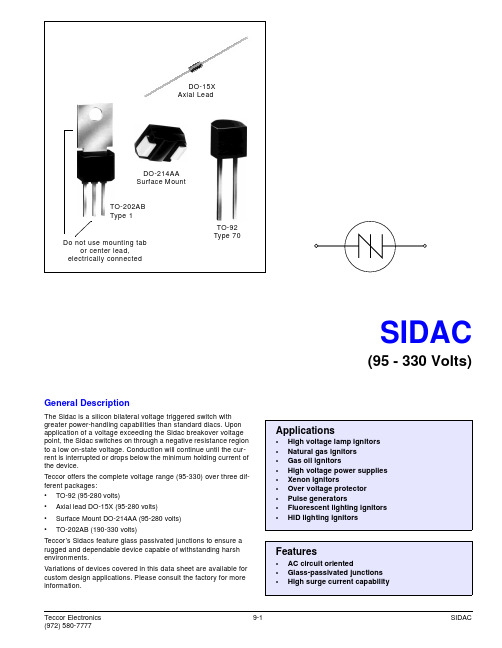
Variations of devices covered in this data sheet are available for custom design applications. Please consult the factory for more information.
acu401驱动器说明书

acu401驱动器说明书
1 工艺流程
整个操作系统由放线、第一牵引、挤出、第二牵引、收线等5个系统组成。
原材料由放线机送出后经过第一牵引单元,接着由挤出单元对其进行塑料包裹处理,一般挤出单元又是由三部份组成(内皮挤出、发泡挤出和外皮挤出),最后经过第二牵引单元由收线机进行收卷处理。
2 工艺技术参数和选型
1)放线单元:Lenze驱动器、2.2kW变频电机(带反馈),轮盘Dmax=600mm,
皮带轮速比1:2;
2)牵引单元:Active驱动器、2.2kW变频电机、牵引盘D=400mm,减速机速比7:1
3)挤出单元:a) Active驱动器,1.1kW变频电机,4段温控(热电偶);
b) Active驱动器,7.5kW变频电机(带反馈),9段温控(热电偶);
c) Active驱动器,1.1kW变频电机,4段温控(热电偶);
4)牵引单元:Active驱动器、2.2kW变频电机、牵引盘D=400mm,减速机速比7:1
5)收线电机:Lenze驱动器、2.2kW变频电机(带反馈),轮盘Dmax=500mm,
皮带轮速比1:2;
6)线速度:700米/分。
GBU405中文资料

V V V A A V uA uA ℃/W
100 -55 to +150 -55 to + 150
45
TSTG Notes: 1. Mounted on P.C.B. with 0.5 x 0.5” (12 x 12mm) Copper Pads and 0.375” 9.5mm) Lead Length. 2. Mounted on Al. Plate of 2” x 3” x 0.25” 3. Measured at 1.0MHZ and Applied Reverse Voltage of 4.0 Volts.
pF ℃ ℃
- 648 -
元器件交易网
RATINGS AND CHARACTERISTIC CURVES (GBU401 THRU GBU407)
FIG.1- MAXIMUM NON-REPETITIVE FORWARD SURGE CURRENT PER BRIDGE ELEMENT
PERCENT OF RATED PEAK REVERSE VOLTAGE. (%)
- 649 -
.880(22.3) .860(21.8)
.160(4.1) .140(3.5)
GBU
.140(3.56) .130(3.30) 0.125(3.2)x45 CHAMFER .740(18.8) .720(18.3) 9 TYP.
.020R(TYP.) .310(7.90) .290(7.40)
.085(2.16) .065(1.65)
5
AVERAGE FORWARD CURRENT. (A)
4
3
2
1
HEAT-SINK MOUNTG 2" x 3" x 0.25" AI-PLATE
ADMP401-1中文资料

Omnidirectional Microphone with Bottom Port and Analog OutputPreliminary Technical DataADMP401-1Rev. PrBInformation furnished by Analog Devices is believed to be accurate and reliable. However , no responsibility is assumed by Analog Devices for its use, nor for any infringements of patents or other rights of third parties that may result from its use. Specifications subject to change without notice. No license is granted by implication or otherwise under any patent or patent rights of Analog Devices. T rademarks and registered trademarks are the property of their respective owners.One Technology Way, P.O. Box 9106, Norwood, M A 02062-9106, U.S.A.Tel: 781.329.4700 Fax: 781.461.3113 ©2008 Analog Devices, Inc. All rights reserved.FEATURES4.72 mm × 3.76 mm × 1.0 mm surface mount package High SNR: 62 dBAHigh sensitivity: −37 dBVFlat frequency response from 100 Hz to over 12 kHz Low current consumption: <200 μA Single-ended analog output High PSRR: >50 dBCompatible with Sn/Pb and Pb-free solder processes RoHS/WEEE compliantAPPLICATIONSCell phones PC audioDigital cameras Bluetooth headsetsGENERAL DESCRIPTIONThe ADMP401-1 is a high quality, low cost, low power analog output bottom-ported omnidirectional MEMS microphone. The ADMP401-1 consists of a MEMS microphone element and an output amplifier. The ADMP401-1 has a high SNR and high sensitivity, making it an excellent choice for far field applications. The ADMP401-1 has a flat wideband frequency responseresulting in natural sound with high intelligibility. Low current consumption enables long battery life for portable applications. A built-in particle filter provides for high reliability. The ADMP401-1 is available in a thin 4.72 mm × 3.76 mm × 1.0 mm surface mount package. The ADMP401-1 is reflow solder compatible with no sensitivity degradation.FUNCTIONAL BLOCK DIAGRAM07712-001V DD GNDMEMBRANE BACKPLATEOUTPUTFigure 1.ADMP401-1Preliminary Technical DataRev. PrB | Page 2 of 8TABLE OF CONTENTSFeatures .............................................................................................. 1 Applications ....................................................................................... 1 General Description ......................................................................... 1 Functional Block Diagram .............................................................. 1 S pecifications ..................................................................................... 3 Absolute Maximum Ratings ............................................................ 4 ESD Caution .................................................................................. 4 Pin Configuration and Function Descriptions ............................. 5 Typical Performance Characteristics ..............................................6 Handling Instructions .......................................................................7 Pick-and-Place Equipment ..........................................................7 Reflow Solder .................................................................................7 Board Wash ....................................................................................7 Outline Dimensions ..........................................................................8 Ordering Guide .. (8)Preliminary Technical DataADMP401-1Rev. PrB | Page 3 of 8SPECIFICATIONST A = 25°C, V DD = 1.8 V , unless otherwise noted. All minimum and maximum specifications are guaranteed. Typical specifications are not guaranteed. Table 1.Parameter Symbol Test Conditions/Comments M in Typ Max Unit PERFORMA NCE Directionality Omni Sensitivity 1 kHz, 94 dB SPL −40 −37 −34 dBV Signal-to-Noise Ratio SNR 60 62 dBA Equivalent Input Noise EIN 32 dBA SPL Frequency Response 100 Hz to 10 kHz −2 0 +2 dB 100 Hz to 12 kHz −3 0 +2 dB Total Harmonic Distortion THD 105 dB SPL 3 %Power Supply Rejection Ratio PSRR 217 Hz, 100 mV p-p square wave super-imposed on V DD = 1.8 V50 dB Maximum Acoustic Input Peak 120 dB SPLPOWER SUPPLY Supply Voltage V DD 1.5 3.6 V Supply Current I S 200 μA OUTPUT CHARACTERISTICS Output Impedance Z OUT 200 Ω Polarity N oninverting 11Positive going (increasing) pressure on the membrane results in a positive going (increasing) output voltage.ADMP401-1Preliminary Technical DataRev. PrB | Page 4 of 8ABSOLUTE MAXIMUM RATINGSTable 2.Parameter Rating Supply Voltage 3.6 V Sound Pressure Level (SPL) 160 dB Mechanical Shock 20,000 gVibration Per MIL-STD-883G Temperature Range −40°C to +85°CStresses above those listed under Absolute Maximum Ratings may cause permanent damage to the device. This is a stress rating only; functional operation of the device at these or any other conditions above those indicated in the operationalsection of this specification is not implied. Exposure to absolute maximum rating conditions for extended periods may affect device reliability. ESD CAUTION077T E M P E R A T U R ETIMET TFigure 2. Recommended Soldering ProfileTable 3. Recommended Soldering ProfileProfile Feature Sn63/Pb37 Pb-Free Average Ramp Rate (T L to T P ) 3°C/sec max 3°C/sec maxPreheat Minimum Temperature (T SMIN ) 100°C 150°C Maximum Temperature (T SMAX ) 150°C 200°C Time (T SMIN to T SMAX ), t S 60 sec to 120 sec 60 sec to 120 sec Ramp-Up Rate (T SMAX to T L ) 3°C/sec 3°C/sec Time Maintained Above Liquidous (t L ) 60 sec to 150 sec 60 sec to 150 sec Liquidous Temperature (T L ) 183°C 217°C Peak Temperature (T P ) 240°C + 0°C/−5°C 260°C + 0°C/−5°C Time Within 5°C of Actual Peak Temperature (t P ) 10 sec to 30 sec 20 sec to 40 sec Ramp-Down Rate 6°C/sec max 6°C/sec max Time 25°C to Peak Temperature 6 minute max 8 minute maxPreliminary Technical DataADMP401-1Rev. PrB | Page 5 of 8007712-003BOTTOM VIEW(TERMINAL SIDE DOWN)Not to ScalePIN CONFIGURATION AND FUNCTION DESCRIPTIONSFigure 3. Pin Configuration (Bottom View)Table 4. Pin Function DescriptionsPin No. Mnemonic Description 1 OUTPUT Analog Output Signal. 2 G NDGround. 3 G N D Ground. 4 G N D Ground. 5 V DD Power Supply. 6 G N D Ground.ADMP401-1Preliminary Technical DataRev. PrB | Page 6 of 8TYPICAL PERFORMANCE CHARACTERISTICS–10100–8–6–4–202468100–10–20–30–40–50–60101001k 10kP S R R (d B )712-00510k1k07712-004FREQUENCY (Hz)S E N S I TI V I T Y (dB )Figure 4. Typical Frequency Response FREQUENCY (Hz)07Figure 5. Typical Power Supply Rejection Ratio vs. FrequencyPreliminary Technical DataADMP401-1Rev. PrB | Page 7 of 8HANDLING INSTRUCTIONSPICK-AND-PLACE EQUIPMENTThe MEMS microphone can be handled using standard pick-and-place and chip shooting equipment. Care should be taken to avoid damage to the MEMS microphone structure as follows: •Use a standard pickup tool to handle the microphone. Because the microphone hole is on the bottom of the package, the pickup tool can make contact with any part of the lid surface.•Use care during pick-and-place to ensure that no high shock events above 20 k g are experienced, because such events may cause damage to the microphone.•Do not pick up the microphone with a vacuum tool that makes contact with the bottom side of the microphone. Do not pull air out or blow air into the microphone port. • Do not use excessive force to place the microphone on the PCB.REFLOW SOLDERStandard reflow solder conditions specified in Figure 2 can be used to attach the MEMS microphone to the PCB.BOARD WASHWhen washing the PCB, ensure that water does not make contact with the microphone port. Blow-off procedures and ultrasonic cleaning must not be used.ADMP401-1Preliminary Technical DataRev. PrB | Page 8 of 8092908-OUTLINE DIMENSIONSA0.82Figure 6. 6-Terminal Chip Array Small Outline No Lead Cavity [LGA_CAV]4.72 mm × 3.76 mm Body(CE-6-1)Dimensions shown in millimeters062408-ASECTION A-ADETAIL AFigure 7. LGA_CAV Tape and Reel Outline DimensionsDimensions shown in millimetersORDERING GUIDEodel Temperature Range Package Description Package OptionOrdering Quantity ADMP401-1ACEZ-RL 1−40°C to +85°C 6-Terminal LGA_CAV, 13” Tape and Reel CE-6-1 4,000 ADMP401-1ACEZ-RL71 −40°C to +85°C 6-Terminal LGA_CAV, 7” Tape and ReelCE-6-1 1,0001 Z = RoHS Compliant Part.©2008 Analog Devices, Inc. All rights reserved. Trademarks and registered trademarks are the property of their respective owners. PR 07712-0-10/08(PrB)。
- 1、下载文档前请自行甄别文档内容的完整性,平台不提供额外的编辑、内容补充、找答案等附加服务。
- 2、"仅部分预览"的文档,不可在线预览部分如存在完整性等问题,可反馈申请退款(可完整预览的文档不适用该条件!)。
- 3、如文档侵犯您的权益,请联系客服反馈,我们会尽快为您处理(人工客服工作时间:9:00-18:30)。
TO-71
NOTE: Stresses above those listed under "Absolute Maximum Ratings" may cause permanent damage to the device. These are stress ratings only and functional operation of the device at these or any other conditions above those indicated in the operational sections of the specifications is not implied. Exposure to absolute maximum rating conditions for extended periods may affect device reliability.
BVG1-G2
±50
±50
±50
±50
±50
±50
gfs
2000 7000 2000 7000
2000
7000
2000
7000
2000
7000
2000
7000
VDS = 10V, VGS = 0
f = 1kHz
gos
20
20
20
20
20
20
µS
gfs
1000 2000 1000 2000
1000
2000
• Minimum System Error and Calibration • Low Drift With Temperature From Low Power Supply Voltages • Operates • High Output Impedance
PIN CONFIGURATION
CJ2
元器件交易网
U401 – U406
CORPORATION
ELECTRICAL CHARACTERISTICS (TA = 25oC unless otherwise specified)
SYMBOL PARAMETER Gate-Source Breakdown Voltage Gate Reverse Current (Note 2) Gate-Source Cutoff Voltage Gate-Source Voltage (on) Saturation Drain Current (Note 3) Operating Gate Current (Note 2) Gate-Gate Breakdown Voltage Common-Source Forward Transconductance (Note 3) Common-Source Output Conductance Common-Source Forward Transconductance Common-Source Output Conductance Common-Source Input Capacitance (Note 6) Common-Source Reverse Transfer Capacitance (Note 6) Equivalent Short-Circuit Input Noise Voltage Common-Mode Rejection Ratio Differential Gate-Source Voltage Gate-Source Voltage Differential Drift (Note 4) 95 5 0.5 -.5 U401 MIN BVGSS IGSS VGS(off) VGS(on) IDSS IG -50 -25 -2.5 -2.3 10.0 -15 -10 0.5 -.5 MAX U402 MIN -50 -25 -2.5 -2.3 10.0 -15 -10 0.5 -.5 MAX U403 MIN -50 -25 -2.5 -2.3 10.0 -15 -10 0.5 -.5 MAX U404 MIN -50 -25 -2.5 -2.3 10.0 -15 -10 0.5 -.5 MAX U405 MIN -50 -25 -2.5 -2.3 10.0 -15 -10 0.5 -.5 MAX U406 MIN -50 -25 -2.5 V -2.3 10.0 -15 -10 mA pA nA V VDG = 15V, ID = 200µA VDS = 10V, VGS = 0 VDG = 15V, ID = 200µA TA = 125oC VDS = 0, V GS = 0, IG = ±1µA MAX V pA VDS = 0, IG = -1µA VDS = 0, V GS = -30V VDS = 15V, ID = 1nA UNITS TEST CONDITIONS
mV
10
10
25
25
40
80
µV/ oC
NOTES: 1. Per transistor. 2. Approximately doubles for every 10oC increase in TA. 3. Pulse test duration = 300µs; duty cycle ≤3%. 4. Measured at end points TA, TB, TC. ∆VDD 5. CMRR = 20 log10 , ∆VDD = 10V. ∆ | V − V | GS GS 1 2 6. For design reference only, not 100% tested.
VDS = 15V, VGS = 0
f = 10Hz (Note 6)
CMRR | VGS1 −VGS2 | | ∆VGS1 −VGS2 | ∆T
95 10
95 10
95 15
90 20 40
VDG = 10 to 20V, ID = 200µA (Note 5, 6) VDG = 10V, ID = 200µA VDG = 10V, ID = 200µA TA = -55oC TB = +25oC TC = +125oC
元器件交易网
Dual N-Channel JFET Switch
CORPORATION
U401 – U406
FEATURES ABSOLUTE MAXIMUM RATINGS (TA = 25oC unless otherwise specified) Gate-Drain or Gate-Source Voltage . . . . . . . . . . . . . . . . . 50V Gate Current (Note 1) . . . . . . . . . . . . . . . . . . . . . . . . . . 10mA Storage Temperature Range . . . . . . . . . . . . . -65oC to +200oC Operating Temperature Range . . . . . . . . . . . -55oC to +150oC Lead Temperature (Soldering, 10sec) . . . . . . . . . . . . . +300oC Power Dissipation (TA = 85oC) Derate above 25oC One Side 300mW 2.6mW/ oC Both Sides 500mW 5mW/ oC
1000
2000
1000
2000
1000
2000 f = 1kHz VDG = 15V, ID = 200µA
gos
2.0
2.0
2.0
2.0
2.0
2.0
Ciss
8.0
8.0
8.0
8.0
8.0
8.0 pF f = 1MHz
Crss
3.0
3.0
3.0
3.0
3.0
3.0
en
20
20
20
20
20
20
nV √ Hz dB
ORDERING INFORMATION Part U401-6 XU401-6
S2 D2 G1 D1 G2 S1
Package Hermetic TO-71 Sorted Chips in Carriers
Temperature Range -55oC to +150oC -55oC to +150oC
