HTR-S5智能卡口专用窄波束测速雷达使用说明书
德卡托手持电波流速仪中文操作手册(简称SVR雷达枪)

美国德卡托电子公司手持电波流速仪用户手册德卡托电子公司版权所有德卡托电子公司欢迎你感谢您选择德卡托电子产品—手持电波流速仪(简称SVR雷达枪),它是一种先进的测速雷达,专用于测量水面流速。
测量洪水和急流时,使用入水式测量仪器非常危险,此时,这种电波流速仪测量流速最合适。
电波流速仪集成了许多领先技术特性。
例如,余弦错误修正。
余弦是指枪到所测目标的垂直角和水平角的余弦。
电波流速仪有一个倾斜感应系统,它会自动补偿垂直余弦错误。
垂直余弦错误是当雷达枪和目标的位置不同而形成一个垂直角度时(空间连线与垂直线角度大于10度)而形成的。
软件可补偿水平方向的余弦误差。
雷达枪与目标水平方向的夹角大于10度就产生一个余弦误差。
我们非常希望用户在使用电波流速仪之前学习本手册,这样就会更好的使用这台高级雷达设备。
如果,您对本仪器非常满意,您还可以向德卡托卖方代表询问我们其它的产品。
--------国家资格最老的雷达公司——德卡托电子公司的全体管理人员和员工目录电波流速仪特点 (2)关于这本手册 (2)1、快速开机 (3)1.1、开机设置 (3)1.1.1、插入电池 (3)1.2、开机 (3)1.3、菜单选择项 (4)1.4、测量水面流速 (5)1.5角度补偿 (7)1.5.1、垂直角度补偿 (7)1.5.2、水平角度补偿 (8)2、组件 (9)2.1、电池 (9)2.1.1、卸下电池 (10)2.1.2、电池充电 (10)2.2、显示面板 (10)2.3串行通讯口 (10)3、操作提示 (11)3.1、雷达如何工作 (11)3.2、干扰源和矫正 (11)3.2.1、角度影响(余弦错误效应) (11)3.2.2、电磁干扰(EMI) (13)3.2.3、反馈干扰 (13)3.2.4、无线电频率干扰(RFI) (13)3.2.5、扫描 (13)3.2.6、环境因素:风,雨和雪 (13)4. 注意,清洁和储存 (14)5. 合法资格 (15)6、常见问题的问答(FAQ) (16)电波流速仪特点手持电波流速仪(简称SVR雷达枪)是唯一专用于测量水面流速的仪器,主要测量河流、溪水。
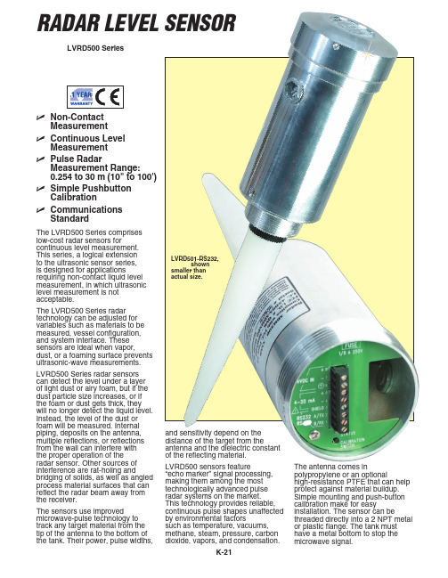
海康威视 LVRD500 系列非接触雷达水位传感器说明书
81,7(' 67$7(6 ZZZRPHJDFRP 7&20(*$
6WDPIRUG &7
&$1$'$ ZZZRPHJDFD /DYDO 4XHEHF 7&20(*$
communication device
Accessories
Conduit Entry: 1⁄2 NPT standard
Model No. Price
Description
Mounting: 2 NPT, or optional sanitary 2" tri-clamp Housing: Aluminum or optional
DPi8 CNi833
$240 310
1⁄8 DIN process meter 1⁄8 DIN controller with relays
316 SS
FW-205
250
Reference Book: The Consumer Guide to
Ingress Protection: NEMA 4 (IP65)
Power Options:
AC: 115 Vac, 60 Hz or 230 Vac, 50 Hz (±20%), 1.7 VA
DC: 12 to 30 Vdc (optional), @ 0.07 A max, 24 Vdc
R load = (Vs–6)/24 mA
Output: 4 to 20 mA, 6.1 μA resolution; 750 Ω (isolated on 4-wire models only); optional RS232 or RS485 communications port
2021年雷达使用手册

道闸雷达欧阳光明(2021.03.07)安装调试手册目录一、前言…………………………………………………… (3)二、产品概述…………………………………………………… (3)三、雷达技术参数……………………………………………………4四、雷达安装规范……………………………………………………5五、接线定义…………………………………………………… (5)六、雷达参数设置……………………………………………………8七、调试…………………………………………………… (9)八、注意事项…………………………………………………… (11)九、保修…………………………………………………… (12)一、前言本手册适用于触发和防砸道闸雷达,以下将描述道闸雷达的安装、参数设置、调试以及注意事项,指导您正确安装和使用道闸雷达。
本雷达采用当今集成度最高的24G雷达单芯片收发方案,具有技术含量高、专业强的特性,使用前请仔细阅读产品安装调试手册。
二、产品概述2.1、工作原理道闸雷达是采用24-24.5GHz可调连续波(FMCW)和高速数字信号处理技术,通过计算接收的回波频率与发射频率之间的频率差来计算目标距离,经逻辑运算后执行外部控制和数据传输。
2.2雷达特点与应用▲ 本产品工作于24-24.5GHz频域区间,全天侯,不受任何气候环境的影响。
▲ 可完全替代“车辆检测器”,实现关闸和防砸功能,省掉了繁琐的切地感线圈工序。
降低人工成本。
▲ 可检测人体,或人体以上大小的非金属物体,可确保人员和物资在闸机下方的安全通行。
▲可用于触发检测,如触发摄像机抓拍。
▲ 可用于警戒区域报警触发器用。
▲ 有流量记录功能,断电不丢失数据。
2.3雷达天线HFSS 仿真效果从上图可看出,要获得更窄的波束,可将雷达横向安装三、雷达技术参数1、输入电压:DC12V 150mA2、工作频率:24-24.5GHz3、调制模式:FMCW4、发射功率:10-15dBm5、波束与闸杆夹角:宽波<15°、窄波<12°6、检测距离:1-6米,±0.2米。
雷达液位计和雷达料位计
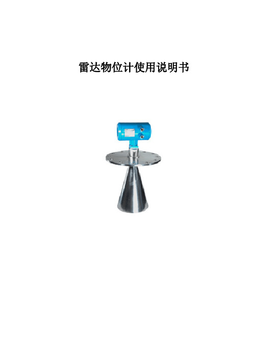
雷达物位计使用说明书目录一、脉冲型雷达物位计测量原理-------------------------------------------------------------------------------------------1 产品简介------------------------------------------------------------------------------------------2 安装指南------------------------------------------------------------------------------------------3 仪表尺寸------------------------------------------------------------------------------------------7测量条件------------------------------------------------------------------------------------------9 编程调试-------------------------------------------------------------------------------------------9 技术参数------------------------------------------------------------------------------------------11 产品选型------------------------------------------------------------------------------------------12二、导波型雷达物位计测量原理-------------------------------------------------------------------------------------------15 产品简介--------------------------------------------------------------------------------------------17 安装指南--------------------------------------------------------------------------------------------18 调试--------------------------------------------------------------------------------------------21 仪表尺寸---------------------------------------------------------------------------------------------22 技术参数--------------------------------------------------------------------------------------------22 产品选型--------------------------------------------------------------------------------------------23一、脉冲型雷达物位计测量原理发射能量很低的极短的微波脉冲通过天线系统发射并接收。
MGTR-S-R 系列雷达水位计 使用手册说明书
MGTR-S-R系列雷达水位计产品使用手册智慧感知系列版本号:1.0.6唐山市柳林自动化设备有限公司 1.0.5-20230511前言唐山市柳林自动化设备有限公司是一家专业从事物联网安全通讯终端、智能仪表与智慧应用系统的研发、生产、销售和系统工程技术服务的高新技术企业、专精特新企业。
公司成立于2007年,拥有1总部(唐山)提供物联网智能终端、数字孪生、SaaS、PaaS、DaaS的研发、生产及销售;1中心(合肥)负责工程系统运维及客户服务,倾听需求,解决问题,成就客户;1研究院(南京)提供生态系统服务10+优质生态合作伙伴、100+核心渠道伙伴、20万+已实施系统现场软硬件设备在线运行。
如您需要任何帮助,您可以关注“唐山柳林自动化”公众号了解产品信息,也可以随时联系我司总部,联系方式如下:地址:河北唐山高新区火炬路410号110楼3号客服热线:130****1802(24小时在线)邮箱:*********************网址:https:///免责声明由于产品版本升级或其他原因,本文档内容会不定期更新。
除非另有约定,本文档仅作为使用指导,本文档中的所述内容、信息和建议均不构成任何明示或暗示的担保。
设备正常操作及安装对于测量的精度以及可靠性影响很大,因此必须保证安装的正常性,并进行反复检查。
保密义务除非唐山市柳林自动化设备有限公司特别授权,否则我司所提供文档和信息的接收方须对接收的文档和信息保密,不得将其用于除本项目的实施与开展以外的任何其他目的。
未经我司书面同意,不得获取、使用或向第三方泄露我司所提供的文档和信息。
对于任何违反保密义务、未经授权使用或以其他非法形式恶意使用所述文档信息或图片的违法侵权行为,我司有权追究法律责任。
版权申明本文档版权属于唐山市柳林自动化设备有限公司,任何人未经我司允许而复制转载该文档将承担法律责任。
版权所有©唐山市柳林自动化设备有限公司2022,保留一切权利。
测速雷达主要设备功能及技术参数

测速雷达主要设备功能及技术参数测速雷达型号:KTR-C3(品牌:KITOZER/开拓者)采用高速DSP信号处理芯片、0.1秒快速捕捉。
1)设计小巧轻便、制作精良。
2)纯铸铁结构,坚固耐用。
3)232串口输出。
4)精确度高,捕捉目标速度快。
5)动态时具有同向功能。
6)静态时可分别检测来车、去车。
7)静态测速范围:0~322 KPH。
8)移动测速范围:19~322KPH。
9)环境要求:温度:-30度 ~ +70度;湿度:0 % ~ 90% 。
10)Ka波段窄波雷达,微波频率:34.7GHz(Ka-band),可有效规避探测狗检测。
11)发射角:±4度。
12)规格:重:0.52kg、直径:6.7cm、长:11.8cm。
13)精确度:+/-1KPH。
高清摄像机(品牌:KITOZER/开拓者)高清摄像机功能:CCD成像,200万象素,主要端口有:闪光灯同步口,通过同步线与闪光灯连接;拍照触发口,当收到外部脉冲触发信号时,高清摄像机会抓取一张图片,脉冲信号由独立的拍照触发器发出;网口(100M),与控制主机连接,接收参数配置,上传图片,也可接收带由协议内容的抓拍命令。
产品详细参数表百万像素变焦镜头日本精工本次中煤平朔公司系统百万像素变焦镜头选型为日本精工SE5018MP产品,AVENIR ETOKU(日本精工)十几年来始终专心于监控镜头的市场发展,成为中国安防监控领域用得最多的专业镜头。
本次系统高清摄像机选型为广州莱安智能化系统开发有限公司出品的KTR200A型高清摄像机。
KTR200A是集成一体的高速彩色/单色智能工业相机,采用总像素200万像素的CCD图像传感器,具有处理速度快、分辨率高、图像质量好等特点。
广泛应用于智能交通、电子警察、卡口、高速公路、停车厂等领域的检测和识别。
百万像素网络拍照摄像一体机,将高清图像抓拍、标清视频摄像完美结合,超高清晰度,分辨率达130万~500万像素,专业用于如平安城市建设、机场、银行、道路卡口监控及牌照识别等安全防范领域,能够为客户提供专业的可定制产品及服务,支持后续增值开发。
雷达测速仪使用说明书
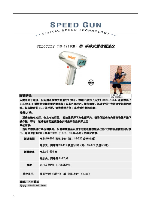
VELOCITY(10-1911CM)型手持式雷达测速仪简要说明:人类乐忠于速度,但问题是很难去测量它!如今,难题已成为了历史!BUSHNELL最新推出了VELOCITY型性能优越的雷达测速仪!以其外型轻巧、操作简便、迅速受到广大测速爱好者的欢迎。
超大清晰的LCD显示屏,读数清晰方便!享受无穷测速乐趣!操作方法:正确安装电池后,合上电池后盖,轻按显示屏下方电源开关,沿物体运动方向瞄准物体并按下操作键,即时,运动物体的速度便会实时显示在显示屏上面!单位切换:当用户想要进行单位切换时,只需将液晶显示屏下方的电源按钮及仪器下方的发射按钮同时按下,即可进行MPH(英里/小时)于KPH(公里/小时)的单位切换。
测速范围汽车:10-200 英里/小时(即:16-320公里/小时)高尔夫、网球等:10-110英里/小时(即:16-177公里/小时)测量距离汽车: 0~450米高尔夫、网球等:0~27米精度+/- 1.0 MPH (+/-2.0KPH)单位显示:英里/小时(MPH)或公里/小时(KPH)显示:LCD数显尺寸:109x213x512mm注意事项:1.若雷达与被测的目标在同一方向上,则测试的速度是准确的,由于实际测试过程存在夹角的问题,会产生测试的误差,随着角度的增加,误差也在增大,这种现象被称为余弦效应。
故在测量物体速度时,请尽量与被测物体的运动路线保持一致或者尽量减小发射波路线与运动物体路线间的夹角。
使测量更加精确稳定!2. 原仪器不带电池,用户可自配。
3.电池寿命根据电池性能及使用频率而定。
4.保修条款:所有型号的产品自售出之日起,均享受一年的免费维修服务,但是人为造成的误操作或者使用不当除外。
此外,保修期内的维修,客户需负担产品邮寄到美国总公司的运费,维修之后返回客户所需的邮寄费用由我们承担。
对于保修期之外的维修服务,对每台仪器还将收取相关的维修费用。
雷达测速卡口的方案.doc
浙江徳威电子有限公司DSIPC4472-6高清网络摄像相机智能卡口系统目录一、徳威电子高清智能卡口系统简介 (3)二、设计原则 (4)三、设计依据 (6)四、系统整体描述 (7)1、系统性能指标 (7)2、系统功能概述 (8)五、系统详细设计 (9)1、系统构成 (9)2、系统软件介绍 (11)3、系统功能 (15)4、系统特点 (18)六、主要设备介绍 (21)1、高清智能网络摄像相机DSIPC4472-6 (21)2、智能高清嵌入式处理器 (22)3、雷达 (22)4、设备清单 (22)一、徳威电子高清智能卡口系统简介近年来,随着经济的快速发展,机动车持有量迅速增加,交通管理现状和需求的矛盾进一步加剧,与车辆相关的刑事和治安案件也逐年上升,特别是盗抢机动车辆案件。
在此情况下,如何利用先进的科技手段提高交通管理水平,抑制交通事故,打击、预防涉车案件,镇慑犯罪分子,提高社会治安管理水平是当前公安交通管理部门亟待解决的问题。
针对公安部门的需求以及我国的道路特点,浙江徳威电子有限公司开发出新一代的高清智能检测系统。
系统利用先进的光电、计算机、图像处理、模式识别、远程数据访问等技术,对监控路段的机动车道、非机动车道进行全天候实时监控并记录相关图像数据。
前端处理系统对所拍摄的图像进行分析,从中自动获取车辆的通过时间、地点、行驶方向、号牌号码、号牌颜色、车身颜色等数据。
并将获取到的信息通过计算机网络传输到卡口系统控制中心的数据库中进行数据存储、查询、比对等处理,当发现肇事逃逸、违规或可疑车辆时,系统会自动向拦截系统及相关人员发出告警信号。
为交通违章查纠、交通事故逃逸、盗抢机动车辆等案件的及时侦破提供重要的信息和证据。
系统采用高性能高清摄像相机作为前端的信息采集设备,图像分辨率高达1600×1200像素,能够在一张照片上清晰的显示车辆的所有细节信息以及司机的面部特征,并具有很高的车牌自动识别率。
高清智能监测系统能及时准确地记录经过卡口的目标信息,不但可以随时掌握出入辖区的车辆流量状态,对超速等违章行为进行处罚,还可以准确记录相关数据信息,为公安刑侦提供重要的参考依据。
雷达测速美国STALKER手持式警用雷达测速仪中文使用说明书
雷达测速美国STALKER手持式警用雷达测速仪中文使用说明书使用说明及显示信息:"TEST":表示系统正在自检。
"PASS":表示系统已通过自检。
"FAIL":表示系统自检失败,此时应将设备送修。
"SEn" :表示系统处于灵敏度设置状态,灵敏度设置用以调节测速范围和巡逻车时速下限。
"SEn1"到"SEn4"表示当前设置,其中"SEn1"测速范围最小,"SEn4"测速范围最大。
右边的数字"5"或"20"表示具体的车速下限。
例如"SEn4.20"的含义是使用32kph 的巡逻车速下限的最大测速范围。
"PS" :"PS5"或"PS20"表示系统正在使用遥控器设置巡逻车下限。
"ON" :测速仪充电完毕且无其他信息显示时,窗口一直显示"ON"标记。
"VOL" :VOL0- VOL9表示音量级别。
"SQL" :SQL和SQL表示静噪设置,详见下述。
"LOCK":表示系统正在进行速度锁定。
"REL" :表示正在清除已锁定的信息。
"MOV" :表示正在使用遥控器将测速仪从"固定模式"调至"移动模式"。
"STA" :表示正在使用遥控器将测速仪从"移动模式"调至"固定模式"。
"LOW" :表示电池将用尽--低于7.7V。
"DEAD":表示电池电力不足--低于7.2V,测速仪无法继续使用。
胎装雷达PWD50 PWD52可见度传感器用户手册说明书
Vaisala Visibility Sensor PWD50design helps sustaining accurate measurement results. VersatilityThe PWD50 architecture allows for easy integration to existing or newly designed systems in a cost efficient manner. The sensor can be mounted in many ways on existing masts. The electrical interfaces are in a single cable. Versatility is further enhanced with various options, such as pole masts, a selection of mounting adapters, power supply cabinets, and a modem for long distance communication.The PWD50 can also be upgraded with present weather sensing capabilities to PWD52. The upgrade enables a wide range of valuable outputs including present weather, precipitation type, precipitation rate and accumulation. These complement the versatile use of the sensor. Robust and Dependable The downward-facing sensor hoods protect the optical surfaces from contamination, resulting in low maintenance needs and costs. The optional hood heaters prevent the buildup of ice and/or snow in the optical path.Solid Track Record Thousands of PWD series sensors have been installed all around the world. They have undergone rigorous test programs. In the field, PWD sensors have demonstrated very low failure rates. They have proved their robustness in the harshest climates and most demanding conditions, ranging from offshore to desert and from airport to roadside.Features/Benefits▪Accurate, traceablemeasurement of prevailingvisibility▪Upgradable▪Versatile and easy to install;easy to integrate▪Robust and dependable▪Weather-proof design reducesneed for maintenance Dependable operation of automatedobservation networks is a must today.Maritime observing systems need towork in inhospitable environmentsand also meteorological institutesface tough productivity andperformance prerequisites. TheVaisala Visibility Sensor PWD50answers these needs with a mixtureof robustness, dependability,versatility and reliability. The PWD50measures visibility from 10 m up to35 km.Accurate VisibilityMeasurementCalibrated with reference to a highlyaccurate transmissometer, thePWD50 uses the proven forward-scatter measurement principle tomeasure Meteorological OpticalRange (MOR). The sensor optics arewell-protected against contamination:the optical components pointdownwards and hoods protectthe lenses against precipitation,spray and dust. This weather-proofPWD50 reports reliably meteorological visibility from 10 meters to 35 kilometers.Technical DataRef. B211069EN-A ©Vaisala 2010This material is subject to copyright protection, with allcopyrights retained by Vaisala and its individual partners. Allrights reserved. Any logos and/or product names are trademarks of Vaisala or its individual partners. The reproduction, transfer, distribution or storage of information contained in this brochure in any form without the prior written consent of Vaisala is strictly prohibited. All specifications — technical included — are subject to change without notice.For more information, visit or contact *********************MechanicalDimensions 199 mm (h) x 695 mm (w) x 404 mm (d)(7.83” (h) x 27.36 “ (w) x 15.91”(d))Weight3 kg (6.61 lb.)Visibility measurementOperating principleForward scatter measurementMeasurement range (MOR)10 ... 35000 mAccuracy±10 %, range 10 m ... 10000 m ±20 %, range 10 km … 35 kmElectricalPower supply 12 - 50 VDC (electronics)24 VAC or 24 VDC for hood heater optionPower consumption3 W Options.luminance sensor 2 W (24 V)hood heaters 65 W (24 V)OutputsRS-232 or RS-485 (2-wire)Three programmable relay controls (open collector), visibility alarm thresholds anddelays configurable, fault alarm relay 0 ... 1 mA, 4 ... 20 mA analog currentEnvironmentalOperating temperature -40 ... +60 ˚C(-40 ... +140 ˚F)Operating humidity 0 ... 100 %RHProtection classIP66Electromagnetic compatibilityCE-compliantCompliance has been verified according to the following EMC directivesV erification subject Standard Radiated emissions CISPR 16-1,16-2Radiated susceptibility IEC 61000-4-3,10 V/m Conducted emissions CISPR 16-1,16-2Conducted susceptibility IEC 61000-4-6EFT immunity IEC 61000-4-4ESD immunity IEC 61000-4-2Surge IEC 61000-4-5Accessories/optionsInterface unit with power supplies 115/230VACPole mastHood heaters for winter conditions Support arm for mast installationsPole clamp kit for mast top installations Luminance sensor PWL111Calibration set PWA12Maintenance cable 16385ZZDimensionsIn addition to meteorological observation networks,PWD50 also suits well for use in offshore operations.。
高清智能卡口系统解决方案
高清智能卡口系统一、概述高清智能卡口系统是采用光电技术、图像处理技术、模式识别技术,对受监控车道上的目标信息进行自动采集、识别、存储与处理的一种道路交通现场监视系统。
高清智能卡口系统,以高清视频为基础,以公安实战需求为导向,采用先进的3D模型动态检测跟踪技术,对通过监控区域的所有对象,包括机动车、机动车驾驶人、非机动车、非机动车驾驶人、行人等,都能够清晰捕获。
系统采用独创的识别技术,能自动识别车牌号码、车牌颜色、车牌结构、车标、车型、车身颜色、非机动车司机衣着颜色、行人衣着颜色等信息。
系统能对黑名单车辆进行动态布控,对道路行驶车辆的构成、流量分布进行统计,并能对超速、逆行等异常行驶的车辆进行检测、抓拍及记录。
高清智能卡口系统在打击和预防犯罪、处置突发性事件、规范城市交通秩序等应用中发挥作用,为科技强警、创建和谐社会提供了强有力的支持。
二、系统结构智能高清智能卡口系统主要包括前端信息采集处理子系统和中心应用子系统,这两个子系统通过信息传输子系统相互通信。
高清摄像卡口系统拓扑图前端信息采集处理子系统由智能摄像机、高清镜头、LED补光灯、视频检测器等设备组成(还可视情况选择雷达、线圈、车检器、闪光灯等设备),用于采集运动目标的高清图片、视频,并利用先进的视频处理和图像识别算法,对抓拍目标的特征信息、动态信息、交通参数进行自动提取和前端存储。
信息传输子系统主要由光纤网络、光收发设备、交换机等设备组成,用于将前端采集处理子系统得出的数据通过通讯方式上传至管理中心应用平台。
中心应用子系统(即iVap 平台)主要由接入服务器、数据库服务器、支撑服务器、存储设备、应用服务器、应用客户端等组成,用于接收,存储,发布和应用前端信息采集处理子系统得到的数据。
信息传输子系统中心应用子系统工业交换机前端信息采集处理子系统智能摄像机LED 补光灯智能摄像机LED 补光灯闪光灯闪光灯光端机视频检测器车检器车检器网络雷达雷达可选可选可选可选可选可选核心交换机光端机三、系统优势⏹全目标检测,提供丰富信息资源系统可以抓拍包括机动车、非机动车、行人在内的所有运动目标,对经过的目标均可进行有效记录。
RAPIER窄波束雷达测速仪2019年5月word资料24页

RAPIER细剑窄波束雷达测速仪2019年5月新版用户手册OLVIA JSCSt. Petersburg目录一、系统简介 (3)二、系统组成及工作原理 (3)三、工作方式 (4)四、技术指标 (5)五、系统优越性 (7)六、系统开发样例 (7)七、进口计量器具型式批准证书 (7)八、系统接线协议 (7)九、软件通讯协议 (11)十、测试软件使用说明 (20)十一、机箱研发参考 (21)十二、检定模式及其注意事项 (22)十三、安装调试参考 (23)RAPIER窄波束雷达测速仪一、系统简介产品名称:窄波束/单车道/平板雷达测速仪品牌型号:RAPIER/细剑制造商:俄罗斯奥利维亚(OLVIA)公司机动车雷达测速仪为一种雷达设备,其工作原理为雷达所发射的高频信号照射在其作用范围内的移动目标反射时改变频率值(多普勒效应)。
这种多普勒频移正比于移动目标的速度。
RAPIER型机动车窄波束雷达测速仪的主要特性为狭窄的辐射场型,保证狭窄的探测区域。
被监控的目标车进入狭窄的探测区域之后,雷达测速仪发送触发信号。
在90%的情况下雷达在发送触发信号的时刻,对应的车辆所在的位置会在±1.5m的狭窄的探测区域之内。
当被监控的目标车离开探测区域的时候,该雷达测速仪会确认目标车已离开探测区域,并发送目标车的速度和车长。
这种工作模式保证触发信号和速度值属于同一辆车,因此基于RAPIER型机动车窄波束雷达测速仪开发的测速抓拍取证系统具备正确度趋于100%的抓拍能力。
测速仪由高频发射器、微处理器等部件构成,全部装于符合IP65的密封外壳,通过RS-232通讯协议与外部控制设备(计算机)连接。
该测速仪能够全天候连续工作5000个小时以上。
窄波束雷达顶装方式窄波束雷达侧装方式二、系统组成及工作原理系统组成测速仪为多普勒效应雷达。
其主要特性为狭窄的辐射场型,保证狭窄的探测区域。
测速仪可以用于固定式和便携式的超速抓拍取证系统。
测速仪可以自动探测到被监控路段上的在特定方向以超出特定限速值行使的车辆,并检测该车辆的速度。
FURUNO FR-2125 雷达操作说明
FURUNO FR-2125 雷达操作说明第一部分雷达操作一开机电源开关[POWER]位于控制面版的左上角,按此键可开/关机。
开机后,在约15秒内,荧光屏显示方位圈及数字计时器。
计时器进行3分钟的倒计时,以便对磁控管进行预热。
当计时器到达0:00时,显示荧光屏上显示STBY,表示已处于备妥状态。
在预热及预备状态下,荧光屏显示BRG SIG MISSING (方位信号丢失),还是正常现象,因为天线不转,没有方位(水平)信号产生。
荧光屏底部显示ON TIME 及TX TIME 表示雷达的开机时间及发射时间。
二发射当荧光屏上显示备妥状态时,按控制面板上的[STBY/TX]。
雷达开机时,初始设定为上次使用过的量程及脉冲宽度。
其他参数如屏幕亮度,活动距标圈,电子方位线和菜单中的任选项也设置为上次使用时的设置。
发射开关可使雷达处于预备或发射状态,在发射状态下,天线转动;预备状态下,天线不转。
快速启动:假设雷达刚刚使用过,磁控管仍热,则不需要3分钟预热时间就可使雷达在发射状态工作。
如因操作失误等类似原因关掉了雷达,而又想立即使用,则可以在关机10秒内开机,以快速启动。
注意:1 如在发射状态下,雷达天线不转,请检查控制面板左下角的天线开关是否放在关(OFF)的位置。
2 磁控管老化可导致输出功率下降,为延长其寿命,建议在一段时间内不使用雷达时,将雷达放置在预备状态。
三控制面板[BRILLIANCE] 调整整个荧光屏的亮度[A/C RAIN] 雨雪干扰抑制[A/C SEA] 海浪干扰抑制[GAIN] 增益调节[EBL] 开/关电子方位线,按[ON]键,可在EBL1,EBL2间转换[#1][#2][#3][#4] 功能键[RANGE] 量程[STBY/TX] 发射/预备[VRM] 开/关活动距标圈,按[]键,可在VRM1,VRM2间转换[AUDIO OFF] 确认声音报警,对视觉报警无效[RADAR MENU] 雷达菜单,为雷达操作和雷达图象设置参数[NA V MENU] 设定航行信息参数[PLOT MENU] 雷达绘图菜单[MODE] 选择显示模式,如艏向上,艏船上真方位,北向上,航向向上及真运动[PANEL BRILL] 控制面板的亮度调节[HL OFF] 暂时消除船艏线[OFF-CENTER] 启动或取消本船位置的偏心显示[EBL OFFSET] 启动或取消电子方位线的偏心显示[CU,TM RESET] 将艏线复位到000度,艏向上显示模式。
雷达测距仪使用说明书
雷达测距仪使用说明书一、产品概述雷达测距仪是一种用于测量目标与雷达设备之间的距离的仪器。
本产品采用先进的雷达技术,能够快速、准确地测量出目标物体与雷达设备之间的距离,并将结果以数字显示的形式呈现,方便用户使用和理解。
二、产品特点1. 高精度测量:采用先进的雷达技术,具有高精度测量能力,可满足不同场景下的距离测量需求。
2. 快速响应:测量速度快,响应时间短,能够在短时间内完成距离测量,提高工作效率。
3. 显示清晰:采用数字显示屏,显示结果清晰可见,避免了因解读模糊而引发的错误。
4. 便捷携带:体积小巧,重量轻,方便携带,可随时进行距离测量。
三、产品使用方法1. 打开电源开关,确保雷达测距仪正常启动。
2. 对准目标物体,确保测量范围内无障碍物遮挡。
3. 按下测量按钮,雷达测距仪将开始工作,快速测量目标与设备之间的距离。
4. 结果将在数字显示屏上显示,以米为单位呈现。
用户可以根据需要对测量结果进行记录或进一步处理。
四、使用注意事项1. 请在安全的环境下使用雷达测距仪,避免在恶劣天气或危险区域中使用。
2. 避免将雷达测距仪放置在高温、潮湿或腐蚀性物质附近,以免影响其正常工作。
3. 请注意保护雷达测距仪,避免剧烈摔打或强烈震动,以免损坏设备。
4. 请定期清洁雷达测距仪的表面和镜头,确保测量的准确性和可靠性。
5. 本产品仅用于距离测量,请勿用于其他用途。
五、常见问题解答1. 为什么测量结果不准确?答:请确保目标物体无遮挡物,且距离测量范围内无其他干扰源。
同时,定期清洁雷达测距仪的表面和镜头,确保准确性。
2. 是否可以在夜间使用雷达测距仪?答:本产品支持夜间使用,但在暗光环境下可能会影响测量精度,请尽量确保光线充足。
六、产品维护1. 定期清洁雷达测距仪,避免灰尘或污垢进入设备内部。
2. 如需更换电池,请使用相同规格和品牌的电池进行更换。
3. 如发现设备故障,请联系售后服务部门进行维修处理,不可私自拆卸、修理。
furuno雷达说明书1.1
E+H MicroPilot S FMR530 HART 雷达物位仪简明操作指南
Products
Solutions
简明操作指南 Micropilot S FMR530
雷达物位仪
Services
本文档为 《简明操作指南》;不得替代随箱包装中的 《操作 手册》。 详细信息请参考随箱 CD 光盘中的 《操作手册》和其他文档 资料,或登录以下网址查询: “/deviceviewer”。
目录
Micropilot S FMR530 4...20 mA HART
目录
1 安全指南 . . . . . . . . . . . . . . . . . . . . . . . . . . . . . . . . . . . . . . . . . . . . . . . . . . . . . . . . . . . . . . . . . . . .3
3 接线 . . . . . . . . . . . . . . . . . . . . . . . . . . . . . . . . . . . . . . . . . . . . . . . . . . . . . . . . . . . . . . . . . . . . . . 15
3.1 快速接线指南 . . . . . . . . . . . . . . . . . . . . . . . . . . . . . . . . . . . . . . . . . . . . . . . . . . . . . . . . . . . . . . . . . . . . . . . . . . . . . . . . . . . . 15 3.2 连接测量单元 . . . . . . . . . . . . . . . . . . . . . . . . . . . . . . . . . . . . . . . . . . . . . . . . . . . . . . . . . . . . . . . . . . . . . . . . . . . . . . . . . . . . 18 3.3 等电势连接 . . . . . . . . . . . . . . . . . . . . . . . . . . . . . . . . . . . . . . . . . . . . . . . . . . . . . . . . . . . . . . . . . . . . . . . . . . . . . . . . . . . . . . 19 3.4 防护等级 . . . . . . . . . . . . . . . . . . . . . . . . . . . . . . . . . . . . . . . . . . . . . . . . . . . . . . . . . . . . . . . . . . . . . . . . . . . . . . . . . . . . . . . . 19 3.5 连接后检查 . . . . . . . . . . . . . . . . . . . . . . . . . . . . . . . . . . . . . . . . . . . . . . . . . . . . . . . . . . . . . . . . . . . . . . . . . . . . . . . . . . . . . . 19
雷马林A5杆式雷达覆盖特殊盖子用户手册说明书

Digital Radome ScannerOwner's ManualDocument number: 81313-3Date: February 2009Contents i ContentsImportant information (1)Introduction (1)Intended use (1)Safety notices (1)FCC Notice (2)WARNING (2)WARNING (2)Waste Electrical and Electronic Equipment Directive (2)EMC conformance (2)Declaration of conformity (2)Multi-function display software version (3)Warranty (3)Handbook information (3)Installation (5)EMC installation guidelines (5)Box contents (6)Required tools (6)Digital Radome scanner dimensions (7)18” Digital Radome scanner (7)24” Digital Radome scanner (7)Planning the installation (8)Cable requirements (9)Scanner cables (9)Running the cable to the scanner (9)Power requirements (10)Grounding the radar system (10)Connecting the power and digital cables (11)Mounting the scanner (14)Setting up the scanner (15)Maintenance and troubleshooting (17)Introduction (17)Maintenance (17)Troubleshooting (17)Technical specification (21)RD418D 18”Digital Radome scanner unit (21)RD424D 24”Digital Radome scanner unit (23)Important information 1 Important informationIntroductionThis handbook contains an explanation of how to install, connect and maintain your Digital Radome scanner and covers the following models:•RD418D - 18” 4 kW Digital Radome scanner.•RD424D - 24” 4 kW Digital Radome scanner.Your radar has been designed and manufactured to meet the rigorous demands of the marine environment. However, no machine can perform its intended function unless installed, operated and maintained properly. Please carefully read and follow the recommended procedures for installa-tion contained in this handbook.When properly installed and operated, the use of this radar conforms to:•IEEE C95.1 - 2005 - Standard for Safety Levels with respect to Human Exposure to Radio Frequency Electromagnetic Fields, 3 kHz to 300GHz.•ICNIRP Guidelines 1998 - International Commission on Non-Ionising Radiation Protection: Guidelines for limiting exposure to time-varying electric, magnetic and electro-magnetic fields (up to 300GHz) 1998. Intended useThis product is a radar scanner intended for use within a navigational radar system. The intended application is for leisure marine boats and work boats not covered by IMO/SOLAS carriage requirements.Installation and operation of this radar may be subject to individual licensing of the equipment, operator or vessel. You are strongly advised to check with the requirements of the licensing authority of your national administration. In case of difficulty, contact your local Raymarine dealer.Safety notices2 Digital Radome Scanner - User GuideFCC NoticeChanges or modifications to this equipment, not expressly approved in writing by Raymarine Inc., could violate compli-ance with FCC rules and void the operator’s authority to operate the equipment.Waste Electrical and Electronic Equipment DirectiveThe Waste Electrical and Electronic Equipment (WEEE) Direc-tive requires the recycling of waste electrical and electronicequipment. Whilst the WEEE Directive does not apply to someof Raymarine’s products, we support its policy and ask you to be aware of how to dispose of this product.The crossed out wheelie bin symbol, illustrated above, and found on our products signifies that this product should not be disposed of in general waste or landfill.Please contact your local dealer, national distributor or Raymarine Tech-nical Services for information on product disposal.EMC conformanceAll Raymarine equipment and accessories are designed to the best industry standards for use in the recreational marine environment. The design and manufacture of Raymarine equipment and accessories conform to the appropriate Electromagnetic Compatibility (EMC) standards, but correct installation is required to ensure that performance is not compromised. Declaration of conformityRaymarine UK Limited hereby declare that the products to which this manual relates comply with the appropriate requirements and provisions of the R&TTE Directive 1999/5/EC.Important information 3Multi-function display software versionThe Digital Radome scanner can be connected directly to a C-Series or E-Series display, or to a C-Series, E-Series or G-Series display via a SeaTalk hs switch.The Digital Radome scanner is compatible with the following multi-func-tion displays:•C90W, C120W, and C140W C-Series displays.•E80, E120 E-Series displays.•G120, G150, G170, and G190 G-Series displays.For operation of your scanner, the multi-function display unit requires the latest software version.To find out whether your display is using the latest software version, switch on the display and check the version number on the navigation warning screen. However, if a scanner is not connected to the multi-function display, the version number will only be displayed for 10 seconds.Handbook informationThe technical and graphical information contained in this handbook, to the best of our knowledge, was correct as it went to press. However, our policy of continuous improvement and updating may change product specifica-tions without prior notice. As a result, unavoidable differences between the product and handbook may occur from time to time.Installation 5 InstallationEMC installation guidelinesAll Raymarine equipment and accessories are designed to the best industry standards for use in the recreational marine environment.Their design and manufacture conforms to the appropriate Electromagnetic Compatibility (EMC) standards, but correct installation is required to ensure that performance is not compromised. Although every effort has been taken to ensure that they will perform under all conditions, it is important to understand what facts could affect the operation of the product.The guidelines here describe the conditions for optimum EMC performance, but it is recognized that it may not be possible to meet all of these condi-tions in all situations. To ensure the best possible conditions for EMC performance within the constraints imposed by any location, always ensure the maximum separation possible between different items of electrical equipment.For optimum EMC performance, it is recommended wherever possible:•Raymarine equipment and cables connected to it are:•At least 3 ft. (1m) from any other equipment transmitting or carrying radio signals. In the case of Single Side Band (SSB) radio,the distance should be increased to 7 ft. (2m).•More than 7 ft. (2m) from the path of a radar beam. A radar beam can normally be assumed to spread 20 degrees above and belowthe radiating element.•The equipment is supplied from a separate battery to that used for engine start. Voltage drops below 10.8 V, and starter motor transients, can cause the equipment to reset. This will not damage the equipment, but may cause the loss of some information and may change the oper-ating mode.•Only Raymarine-specified cables must be used. Cutting and rejoining these cables can compromise EMC performance.6 Digital Radome Scanner - User GuideBox contentsComponents are dependant on your system package, but are either:•18” 4 kW Digital Radome scanner, or•24” 4 kW Digital Radome scanner.•Fixing bolts and washers.•Denso Paste.•Handbook.Required toolsInstallation 7 Digital Radome scanner dimensions18” Digital Radome scanner24” Digital Radome scanner8 Digital Radome Scanner - User GuidePlanning the installationMount the scanner as high as possible above the waterline for better long range performance, but make sure it:•is above head height.•is easily accessible.•is as near to the boat’s centerline as possible.•is on a rigid and stable platform.•is clear of large objects such as the flybridge, large engine stacks,searchlights, horns or masts.•is clear of heat and fumes.•is at least 1 m away from a magnetic compass or other equipmentantenna.Don’t put the scanner so high, that it is affected by the pitching and rolling of the boat.Mount the scanner so that the array rotates parallel to the waterline.The radar beam is approximately 25o wide in the vertical direction, giving good target detection when your boat pitches and rolls.Planing hull and some displacement hull boats adopt a higher bow angle when the boat is at cruising speed, giving poor target detection. It may be necessary to lower the radar beam back towards the parallel, by shimming the rear of the radar, so that the beam points slightly down when the boat is at rest. Refer to the diagram on page14 for more information.Installation 9Cable requirementsYou must consider the following points before installing the system cables:•You need to connect the scanner to the multi-function display unit and power (and, if appropriate, via a SeaTalk hs switch).•All cables should be adequately clamped and protected from physical damage and exposure to heat - avoid running cables through bilges or doorways, or close to moving or hot objects.•Acute bends must be avoided. The digital cable for connecting the Digital Radome scanner to a multi-function display and power source has a minimum bend radius of 45mm (or diameter of 90mm).•Where a cable passes through an exposed bulkhead or deckhead, a watertight gland or swan neck tube should be used.•Avoid cutting and rejoining cables.Scanner cablesRunning the cable to the scannerDO NOT pull the cable through bulkheads using a cord attached to the connector. This could damage connections. The cable connector is at the rear of the scanner unit. If the unit is mounted on a hollow mast, the cable may be run inside the mast and connected to the unit. Make sure that the cable does not chafe where it enters and exits the mast. To minimize electrical interference try to avoid running radar cables near other onboard electrical equipment. It is also good practice to avoid running radar cables in parallel with other antenna or power cables.Digital cableA digital cable, illustrated below, is required. This provides both power and SeaTalk hs signals to the Digital Radome scanner. It is fitted with a SeaTalk hs plug, and power cores for connecting to the scanner.•Part No. A55076 - 5 m cable.•Part No. A55077 - 10 m cable.•Part No. A55078 - 15 m cable.•Part No. A55079 - 25 m cable.The following extension cables are also available:•Part No. A92141 - 2.5 m extension cable.•Part No. A55080 - 5 m extension cable.•Part No. A55081 - 10 m extension cable.For boats with 12 V DC power systems, the maximum cable length is 25 m (including any extension). If you need to run a longer cable length with a 12v supply, please contact Raymarine technical support for further advice. Note: Do not make your own cables for use with the Digital Radome scanner. Only use official Raymarine cables.10 Digital Radome Scanner - User GuidePower cablesDigital Radome radar systems are intended for use on boat’s DC power systems operating in the range 12 to 24 V DC. The Digital Radome scanners should not be used on nominal 32 V systems.If you are replacing an existing (Analog) Radome scanner with a Digital Radome scanner, you must replace the existing cable with a digital cable, as described on page9.Power requirementsThis radar is NOT recommended for use on ‘positive’ ground boats. The power cable earth screen must be connected to the boat’s ground.The boat’s power system should be either:•Negative grounded, with the negative battery terminal connected to the boat’s ground, or,•Floating with neither battery terminal connected to the boat’s ground. The following diagram shows the cable’s power and ground connections: Fuse requirementsThe power connection to the Digital Radome scanner should be made at either the output of the battery isolator switch, or at a DC power distribu-tion panel. The power connection must be protected by a thermal circuit breaker or fuse, fitted close to the power source. The following table details the fuse requirements for both 18” and 24” Digital Radomes: WARNING: If there is not a thermal circuit breaker or fuse in your power circuit (for example, fitted to your DC distribu-tion panel), you must fit an inline breaker or fuse to the positive (red) connection of the power cable. Grounding the radar systemIt is important that an effective radio frequency (RF) ground is connected to the radar system.You must ground the radar by connecting the drain wire (screen) of the power cable to the nearest ground point of your boat’s RF ground system. Full details can be found in the Owner’s Handbook for your multi-function display unit.If you need to extend the wire, the extension wire should be an 8 mm braid or 6 mm2 (AWG 10) multi-strand cable.If your vessel does not have an RF system, connect the drain wire to the negative battery terminal.Note: Use only this ground connection.Table2-1: Fuse requirements Power supply Device Rating 12 V Isolator Switch20 AThermal Breaker10 AFuse15 A 24 V Isolator Switch15 AThermal Breaker 5 AFuse8 AInstallation 11The following must be observed:•disconnected after the initial installation.•power distribution panel.••hand-tightened only.12 Digital Radome Scanner - User Guide Digital Radome connected to networked E-SeriesInstallation 13 Digital Radome connected to G-Series display14 Digital Radome Scanner - User Guide Mounting the scanner Preparing the mounting holesNote: The M8 bolts that secure the Digital Radome scanner to the mounting platform require a torque of 20Nm (177lbf.in). Use thesupplied "Denso Paste" to lightly coat the mounting bolts.16 Digital Radome Scanner - User GuideSystem checksSystem checkBefore performing any functional tests, make sure:•All securing bolts are fully tightened and mechanical locking washers as specified are in place.•All connections have been made.•All connecting wires are secured and protected as necessary.If you have installed the radar yourself, ask your local Raymarine autho-rized installation dealer to check the installation.Set up, alignment and timing checksSwitch on and initial set up1.Press and hold the POWER key of your multi-function display unit untilthe unit beeps. The magnetron warm-up sequence should start, after which the unit should enter standby mode.2.Power on the Digital Radome scanner, using the relevant softkey onyour multi-function display.3.If necessary, adjust the brightness on your multi-function display unit.4.If necessary, change the default language settings. Transmission checkEnsure that all personnel are clear of the scanner and switch to transmit mode. Run through the radar operations as described in the relevant multi-function display unit’s Owner’s Handbook and check that all the expected data is displayed.Bearing alignmentWith the system correctly installed, check the bearing alignment to ensure that targets appear at their correct bearing relative to the boat’s bow. Adjust the alignment as necessary.Display timing adjustmentIt is advisable to check the display timing before using the system for navi-gation. For instructions on how to do this, refer to the installation guide for your multi-function display.Maintenance and troubleshooting 17 Maintenance and troubleshootingCAUTION: System powerAlways turn the radar system OFF before carrying out any routine maintenance on the scanner or nearby equipment. IntroductionDO NOT remove the rear cover of the multi-function display or the external cover of the Digital Radome scanner. There are no user serviceable parts or adjustments. DO NOT attempt to service the equipment. MaintenanceMaintenance is limited to the following periodical checks:•Examine the cables for signs of damage, such as chafing, nicks and cuts. If the connector is showing signs of corrosion, lightly grease the threads of the connector with “Renolit Aqua 2 Calcium” grease.•Check that the cable connectors are firmly attached.•Make sure the scanner is still securely attached to the mounting surface.•Once a year, remove, grease and re-attach the mounting bolts securing the scanner.TroubleshootingThe following table will help you identify the most likely cause of a problem, and the corrective action required to restore normal operation.Problem Possible causes and solution “No Data” or “No Scanner”message1.Check that the cable connecting theDigital Radome scanner to the multi-function display unit is firmly attachedand undamaged.2.Check relevant scanner fuses andbreakers.3.Check that the power source is of thecorrect voltage and sufficient current.4.Software mismatch between equip-ment may prevent communication.Contact Raymarine technical support.If using a SeaTalk hs Switch:5.Check that all radar scanners arecorrectly connected to the SeaTalk hsswitch.6.Check the status of the SeaTalk hsswitch.7.Check that SeaTalk hs cables are freefrom damage.The bearing displayed on themulti-function display is notthe same as the actualbearing.Perform the bearing alignment proce-dure described in the installation guidefor the relevant multi-function displayunit.Appendix A: Technical specification RD418D 18”Digital Radome scanner unit GeneralApprovalsCE - conforms toFCC - conforms toIndustry Canada - conforms to 1999/5/EC47CFR Part 2 and Part 80 RSS138DimensionsΦ521 x 247 mm (20.5 x 9.7 in)Weight9.5 kg (21 lbs)Input Voltage 12 - 24 V DC (from multi-function displayunit)Power Consumption40 W (20 W Standby) Environmental Waterproof to IPX 6Temperature range:-10° to +55°CHumidity limit:up to 95% at 35°CMaximum wind speed for satisfactoryoperation: 100 KtsMaximum Range Scale48 Nautical miles (Nm)TransmitterTransmitter Fre-quency9405 ± 25 MHzPeak Power Output 4.0 kW (nominal) Transmitter Solid-state modulator drivingMagnetronRange (Nm)Expanded Range (Nm)Pulse Width (ns)PRF (kHz)0.125, 0.25N/A75 ± 10ns 3.0 0.50, 0.750.125, 0.25100 ± 10ns 3.0N/A0.5, 0.75150 ± 10ns 3.0 1.5N/A250 ± 5% 3.03 1.5350 ± 5% 2.0N/A 3.0450 ± 5% 1.5N/A N/A600 ± 5% 1.3 6.0 6.0 1.0 μs ± 5%740 Hz Standby Mode magnetron heater and controlleft on, all other services off Duplexer CirculatorDigital Radome Scanner - User GuideAntennaAntenna Type Patch arrayBeam Width (nominal) 4.9° horizontal, 25° verticalPolarization HorizontalRotation Rate24 rpm (nominal)ReceiverIF Frequency60 MHz (nominal)Receiver Characteristic LogarithmicReceiver Noise Figure Less than 5 dB(including Low Noise Converter/Limiter & IFReceiver)Receiver Bandwidth12/3/0.7/0.5 MHzRD424D 24”Digital Radome scanner unit GeneralApprovalsCE - conforms toFCC - conforms toIndustry Canada - conforms to 1999/5/EC47CFR Part 2 and Part 80 RSS138DimensionsΦ652 x 247 mm (25.67 x 9.7 in) Weight10.0 kg (22 lbs)Input Voltage 12 - 24 V DC (from multi-function displayunit)Power Consumption40 W (20 W Standby) Environmental Waterproof to IPX 6Temperature range:-10° to +55°CHumidity limit:up to 95% at 35°CMaximum wind speed for satisfactoryoperation: 100 KtsMaximum Range Scale48 Nautical miles (Nm)TransmitterTransmitter Fre-quency9405 ± 25 MHzPeak Power Output 4.0 kW (nominal) Transmitter Solid-state modulator drivingMagnetronRange (Nm)Expanded Range (Nm)Pulse Width (ns)PRF (kHz)0.125, 0.25N/A75 ± 10ns 3.0 0.50, 0.750.125, 0.25100 ± 10ns 3.0N/A0.5, 0.75150 ± 10ns 3.0 1.5N/A250 ± 5% 3.03 1.5350 ± 5% 2.0N/A 3.0450 ± 5% 1.5N/A N/A600 ± 5% 1.3 6.0 6.0 1.0 μs ± 5%740 Hz Standby Mode magnetron heater and controlleft on, all other services off Duplexer CirculatorDigital Radome Scanner - User GuideAntennaAntenna Type Patch arrayBeam Width (nominal) 3.9° horizontal, 25° verticalPolarization HorizontalRotation Rate24 rpm (nominal)ReceiverIF Frequency60 MHz (nominal)Receiver Characteristic LogarithmicReceiver Noise Figure Less than 5 dB(including Low Noise Converter/Limiter & IFReceiver)Receiver Bandwidth12/3/0.7/0.5 MHz。
- 1、下载文档前请自行甄别文档内容的完整性,平台不提供额外的编辑、内容补充、找答案等附加服务。
- 2、"仅部分预览"的文档,不可在线预览部分如存在完整性等问题,可反馈申请退款(可完整预览的文档不适用该条件!)。
- 3、如文档侵犯您的权益,请联系客服反馈,我们会尽快为您处理(人工客服工作时间:9:00-18:30)。
HTR-S5智能卡口专用窄波束测速雷达使用说明书合肥海天电子科技有限公司1 概述HTR‐S5型测速雷达是采用高集成MMIC、数字锁相、高速DSP信号处理技术设计完成的全数字K‐波段窄波束测速雷达。
A.射频前端采用高集成度MMIC极大提高了系统工作可靠性和产品一致性;B.采用数字锁相技术,在‐40~+85℃工作范围内频偏小于500KHz(国标为:±45MHz);C.可靠的车辆方向(来向、去向)辨认。
D.用户可编触发和速度输出模式,方便用户触发各种相机,提高设备现场适应性。
E.速度融合模型可有效消除大车、紧邻车等现场问题。
F.自检测逻辑可自动检测系统各部分状态,实现故障自动报警。
2 基本技术指标ID 指标名称 具体描述1 工作波段 K-波段2 工作频率 24.150GHz3 波束宽度 水平4.5;垂直6度4 作用距离 ≥100米5 通信方式 RS232-C 默认波特率115200bps6 脉冲触发 TTL脉冲;峰值为+5V7 响应时间 < 30毫秒8 测速范围 5 ~ 250km/h9 测速精度 ≤-1km/h10 测量方向 双向、单向(来向、去向)模式可配置11 输出结果过滤模式 卡口来向抓拍、卡口去向抓拍12 测速限速 最小过滤速度可配置;超速触发可配置13 灵敏度 可配置14 工作电压 DC 9V ~ 36V 电流不大于450mA15 防护等级 IP6616 温度 -45~85摄氏度17 自检方式 开机自检、周期自检3 接口定义3.1 接口A信号定义ID 引脚序号/颜色 具体描述 备注1 1 (红色) 电源输入正极2 2 (绿色) 电源地线3 3 (橙色) 外部触发TTL输出 高电平触发,脉宽100毫秒4 4 (黑色) 外部触发信号地5 5 (蓝色) RS232C 数据发送 连接到PC串口第2脚6 6 (白色) RS232C 数据接收 连接到PC串口第3脚7 7 (黄色)RS232C 信号地 连接到PC串口信号地8 8 (棕色)屏蔽层地线3.2 串口通信规定ID 名称 具体描述 备注1 起始位 1位2 数据位 8位3 停止位 1位4 校验模式 无5 流控方式 无6 波特率 115200bps4通信协议5.1 通信协议概述主机发送给雷达的控制命令采用:文本命令+空格+参数列表+回车组成。
举例:查看雷达设备是否存在命令为chk+回车雷达回复给主机的状态信息:采用定长度文本回复,利于主机解析。
雷达返回给主机的信息分为2种长度,配置命令返回消息长度为4个字节;速度信息返回为18个字节。
具体格式如下:配置命令返回消息:帧头 信息内容 帧尾占用字节 1Byte 2Byte 1Byte} 具体定义 { ok 表示配置成功er 表示配置失败速度信息返回消息:帧头 信息内容 帧尾占用字节 1Byte 16Byte 1Byte具体定义 { 详见各个状态返回定义 }5.2 具体通信协议列表5.2.1 主机发送给雷达的配置命令协议ID 命令功能 文本命令 备注1 主机查询雷达是否存在 chd 命令后加回车(0x0D),下同2 主机配置雷达安装模式 set▁o▁模式 ▁表示空格,下同3 主机配置雷达倾角命令 set▁a▁角度4 主机配置雷达灵敏度命令 set▁s▁数值5 主机配置过滤最低速度 set▁t▁l▁数值6 主机配置超速抓拍速度 set▁t▁h▁数值7 主机配置雷达信息输出格式 set▁t▁f▁模式标示8 主机配置雷达恢复出厂模式 set▁y9 主机配置雷达存储当前配置 set▁b10 主机获取配置信息命令 get▁c11 主机重新启动雷达命令 reboot5.2.2 雷达主动发送给主机的信息协议ID 命令功能 信息标识 备注1 当前机动目标速度 vf5.3 主机发送给雷达详细配置命令5.3.1 主机查询雷达是否存在命令ID 主题 详细描述 备注1 命令组成 chk 后面需要加入回车符2 参数 无3 超时时间 1秒4 雷达返回 具体返回字符串:{ok}或{er}具体含义为:{ok} 表示系统内部各组件正常{er} 表示系统内部自检错误5.3.2主机发送配置雷达安装和抓拍模式ID 主题 详细描述 备注1 命令组成 set2 参数 参数1:o,子命令参数参数2:1 龙门架安装来向抓拍车头 系统默认配置3 龙门架安装去向抓拍车尾3 超时时间 1秒4 雷达返回 具体返回字符串:{ok}或{er}具体含义为:{ok} 表示系统内部各组件正常{er} 表示系统内部自检错误5 举例 龙门架安装正面抓拍车头,则发送命令:set空格o空格1回车5.3.3 主机发送配置雷达倾斜角度命令ID 主题 详细描述 备注1 命令组成 set2 参数 参数1:a ,子命令参数。
参数2:角度数值。
基本格式为ab.cde格式,精确到小数点后3位数。
举例:12.345 表示12.345度。
9.1 表示9.1度。
3 超时时间 1秒4 雷达返回 具体返回字符串:{ok}或{er}具体含义为:{ok} 表示系统内部各组件正常{er} 表示系统内部自检错误5 具体举例 配置倾斜角度9.5度,则发送命令:set空格a空格9.5 回车5.3.4 主机发送设置雷达灵敏度命令ID 主题 详细描述 备注1 命令组成 set2 参数 参数1:s,子命令参数。
参数2:灵敏度数值。
该灵敏度取值范围为:1~255之间。
后面需要加入回车符1 为最高灵敏度度 255为最低灵敏度 系统默认值:1283 超时时间 1秒4 雷达返回 具体返回字符串:{ok}或{er}具体含义为:{ok} 表示系统内部各组件正常{er} 表示系统内部自检错误5 具体举例 配置灵敏度为200,则发送命令:set空格s空格200 回车5.3.5主机配置雷达过滤最低速度ID 主题 详细描述 备注1 命令组成 set2 参数 参数1:t参数2:l,子命令参数。
参数3:最低速度过滤阀值。
格式为abc.d,保留一位小数点,单位为km/h。
默认为5km/h;取值为5km/h~50km/h。
3 超时时间 1s4 雷达返回 具体返回字符串:{ok}或{er}具体含义为:{ok} 表示系统内部各组件正常{er} 表示系统内部自检错误5 举例 配置低于25km/h下速度不输出,则发送:set空格t空格l空格25回车5.3.6 主机配置雷达超速触发速度ID 主题 详细描述 备注1 命令组成 set2 参数 参数1:参数2:h,子命令参数参数3:超速触发速度,格式为abc.d,保留一位小数点,单位为km/h默认为60km/h3 超时时间 1秒4 雷达返回 具体返回字符串:{ok}或{er}具体含义为:{ok} 表示系统内部各组件正常{er} 表示系统内部自检错误5 举例 设置超速触发速度为90km/h,则发送命令:set空格t空格h空格90回车5.3.7 主机配置雷达恢复到出厂模式ID 主题 详细描述 备注1 命令组成 set2 参数 参数1:y,子命令参数。
3 超时时间 1s4 雷达返回 具体返回字符串:{ok}或{er}具体含义为:{ok} 配置成功{er} 配置失败5 举例 雷达恢复到出厂模式:则发送命令:set空格y回车5.3.8主机配置存储当前配置到存储文件ID 主题 详细描述 备注1 命令组成 set2 参数 参数1:b,子命令参数。
3 超时时间 1s4 雷达返回 具体返回字符串:{ok}或{er}具体含义为:{ok} 配置成功{er} 配置失败5 举例 雷达存储当前配置到存储文件,则发送命令:set空格b回车5.3.9主机发送给雷达获取配置信息命令ID 主题 详细描述 备注1 命令组成 get2 参数 参数1:u,获取用户配置信息。
3 超时时间 1s4 雷达返回 具体返回字符串:具体配置信息列表。
5 举例 获取雷达所有配置信息,则发送命令:get空格u回车5.4 雷达主动发送给主机的详细协议5.4.1 雷达发送最快速度目标速度ID 主题 详细描述 备注1 命令组成 vf2 参数 参数1:设备标识号参数2:最快速度目标速度参数3:帧检测序号3 发送频率 <50ms秒一次4 举例 {vf,5+123.45,1239}设备标识号为5的雷达发送的1239帧内检测到的最快目标速度为+123.45km/h.固定长度5.4.2 雷达回复给主机用户配置信息ID 主题 详细描述 备注1 命令组成 gu2 参数 参数1:安装模式参数2:安装倾斜角度参数3:灵敏度参数4:最低过滤速度参数5:超速触发速度参数6:数据输出格式 以上各参数采用','进行分割3 举例 雷达返回:{gu,1,+17.00,+120,+5.0,+96.00,0}{ 帧头标识gu 用户获取配置信息标示安装模式为1;安装倾斜角度为:17度;灵敏度:120;最低过滤速度:5km/h;超速触发速度:96km/h;数据输出格式:格式0} 帧尾标识 长度不定;每个数据参数以','隔开;。
