XL8004原厂规格书(2014版)
产品规格书完整
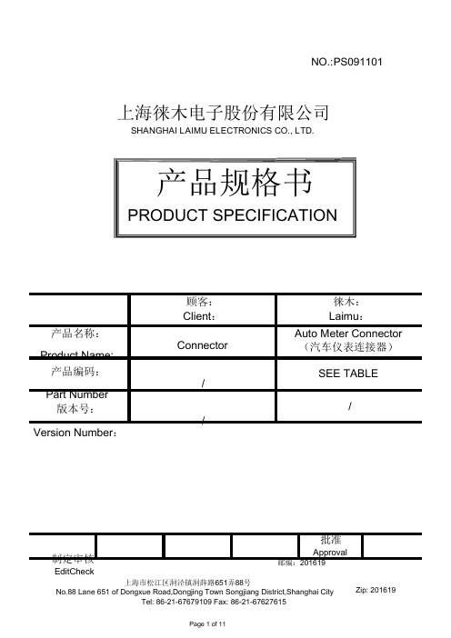
NO.:PS091101上海徕木电子股份有限公司SHANGHAI LAIMU ELECTRONICS CO., LTD.产品规格书PRODUCT SPECIFICATION顾客:Client:产品名称:Connector Product Name:产品编码:/Part Number版本号:/ Version Number:制定审核EditCheck上海市松江区洞泾镇洞薛路651弄88号徕木:Laimu:Auto Meter Connector(汽车仪表连接器)SEE TABLE/批准Approval邮编:201619上海徕木电子股份有限公司SHANGHAI LAIMU ELECTRONICS CO., LTD.编 号PS091101Serial Number 产品规格书Product Specification目版本号/ Version Number 产品名称 Connector Product Name 产品编码 See TablePart Number录CONTENT0更改记录........................................................................................................................................3 1产品描述Product description.. (4)1.1产品简图Outline drawing ..................................................................................................4 1.2产品组成BOM (5)2总体要求General (5)2.1功能描述Functional description ..........................................................................................5 2.2安装位置Mounting location ................................................................................................5 2.3温度范围Ambient temperature range .................................................................................5 2.4额定范围Rating range ........................................................................................................5 3默认测试条件Default test conditions .............................................................................................5 4产品性能Performance . (6)4.1外观Appearance..................................................................................................................6 4.2结构尺寸Dimension.............................................................................................................6 4.3接触电阻Contact resistance...................................................................................................6 4.4绝缘电阻Insulation resistance...............................................................................................6 4.5耐电压Withstand voltage......................................................................................................7 4.6温升Temperature rise............................................................................................................7 4.7插入力Connector Mating Force.............................................................................................7 4.8拔出力Connector Unmating Force.........................................................................................7 4.9端子保持力Terminal to Connector Retention...........................................................................8 4.10振动Vibration....................................................................................................................8 4.11温度循环Temperature cycling..............................................................................................8 4.12耐高温Heat Resistance.......................................................................................................9 4.13耐低温Cold Resistance.......................................................................................................9 4.14盐雾Salt spray...................................................................................................................9 4.15耐焊接热Resistance to soldering heat.................................................................................10 4.16沾锡性Solderability. (10)上海徕木电子股份有限公司SHANGHAI LAIMU ELECTRONICS CO., LTD.编 号PS091101Serial Number 产品规格书Product Specification0更改记录序号 版本号 更改前描述No.: Version Description Before ModificationNumber123456版本号/ Version Number 产品名称 Connector Product Name 产品编码 See TablePart Number更改后描述 批准 日期Description After ModificationApprovalDatePage 3 of 11FOR-TS3-D08-01版本/版次:A1上海徕木电子股份有限公司SHANGHAI LAIMU ELECTRONICS CO., LTD.编 号PS091101Serial Number 产品规格书Product Specification1产品描述Product description1.1产品简图Outline drawing适用于本规格书的产品系列,如下表:P/N.料号No. No. of PIN Color A1.2产品组成BOM1.2.1接触件:黄铜,底镀镍,整体镀锡;版本号/ Version Number 产品名称 Connector Product Name 产品编码 See TablePart NumberB C D E FContact :Brass, Pure Tin plated over Nickel under plating ; 1.2.2塑料本体:PBT+GF15;Housing :PBT+GF15;2总体要求General2.1功能描述Functional description本产品主要适用于汽车仪表控制模块与线束的电力信号传输与连接。
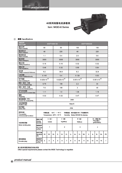
2014说明书40A
电动开窗器控制箱使用说明书FAL-PT型上海菱索智能控制设备有限公司前言●感谢你使用本公司系列产品。
为能正确应用电动开窗器控制系统,请务必先仔细阅读说明书。
●阅读后请将说明书妥善保管及备份,以备随时参考。
●产品安装调试时严禁非专业人员操作。
电动开窗系统的应用一.概述大多数电动开窗器机身的安装为外露式。
根据其工作用途不同有不同的安装方式。
目前已广泛使用于:私人家居﹑别墅﹑体育场馆﹑机场﹑厂房﹑购物中心﹑酒店﹑仓库﹑商务中心﹑机房等高层建筑二.电动开窗器的联动工作联动工作是指电动开窗器与楼宇自动化系统配合使用,一般有如下三个联动系统。
a. 与消防系统联动电动开窗器在消防系统中主要作为窗户开启的执行机构,用于火灾情况下的紧急排烟功能,电动开窗器在整套联动系统中,开窗器的系统具备如下的功能:(1)、后备直流电源浮充工作及断电后直流电源自动切换功能。
后备直流电源大小根据现场系统配置来选择蓄电池的A/H。
(2)、具有指示信号自动返回消防中心功能。
此功能用来判断开窗器的工作状态。
(3)、可独立构成局域火灾预警系统。
即在该系统中有外接烟感、温感接口。
(4)、所有控制信号为无源接触点的开关量信号。
(5)、图下为电动开窗器与消防联动系统示意图。
b. 与室内环境控制系统联动。
在该联动系统中,一般是由电动开窗器根据楼宇监测中心的信号或自测信号自动开启/关闭通风窗、遮阳百叶、窗体阳光反射角度等,用以调整及控制室内的湿度、温度及含氧量(新风量)等,以达到整个系统的环境指标要求。
该联动系统体现楼宇智能的优越性。
C.与计算机系统联动。
该联动系统是由电脑驱动管理主控箱与计算机联接的控制系统。
该系统采用CAN总线通信技术,以微机为核心,是将COMPUTER(计算机技术),AUTO CONTROL (自动控制技术)和CHANGE(转换技术)等技术紧密结合的产品,它具有适应范围广、可扩展性强、维护方便以及抗故障能力强等优点,CAN协议执行非集中化总线控制,在系统中可高灵敏度的执行开窗器的分批次分层次工作,该联动系统的存在更能充分体现楼宇智能的优越性。
XL1530原厂规格书(2014版)
XL1530
FB EN NC VIN
1 2 XL1530 3 4
8 7 6 5
GND GND SW SW
Figure2. Pin Configuration of XL1530 (Top View) Table 1 Pin Description Pin Number 3 4 5,6 7,8 Pin Name NC VIN SW GND Description No Connected. Supply Voltage Input Pin. XL1530 operates from a 3.6V to 18V DC voltage. Bypass Vin to GND with a suitably large capacitor to eliminate noise on the input. Power Switch Output Pin (SW). Output is the switch node that supplies power to the output. Ground Pin. Care must be taken in layout. This pin should be placed outside of the Schottky Diode to output capacitor ground path to prevent switching current spikes from inducing voltage noise into XL1530. Feedback Pin (FB). Through an external resistor divider network, Feedback senses the output voltage and regulates it. The feedback threshold voltage is 0.8V. Enable Pin. Drive EN pin low to turn off the device, drive it high to turn it on. Floating is default high.
集装箱门吊技术规格书

项目名称:海安货场轨道式集装箱门式起重机技术规格书上海铁路局2014 道式集装箱门式起重机项目技术规格书型号:吊架下起升重量40.5 吨名称:轨道式集装箱门式起重机目录1 (5)2. 目概略 (5)3. 目技格 (6)3.1 概括 ..................................................... ⋯⋯⋯3.2 使用境参数 .. (6)3.3 性能参数 (7)3.4 主要外件品牌 (8)3.5 准与范 (9)3.6 主要板厚度 (11)3.7 主要零件资料 (11)3.8 主要气的防等 . (11)4. 通用技要求 (12)4.1 固件和接件 (12)螺栓、螺母接 . (12)、接 . (12)承与密封 . (12)4.2 资料与制作工 (12)资料 (12)制作工 . (13)4.3 接 (13)4.4 表面理与涂装 (14)5. 主要零零件技范 (14)5.1 金属构件 (14)金属构件技范 (14)5.1.2 架 . (15)5.1.3 小架 . (15)大均衡梁和台架 (15)5.2 起升机构 (16)5.3 小运行机构 (16)5.4 大行走机构 (17)5.5 平台、通道、梯和杆 . (18)5.6 集装箱吊具和吊具上架 . (18)5.7 (19)5.8 滑 (20)5.9 卷筒 (20)5.10 减速器 (20)5.11 器 (21)5.12 制器 (21)5.13 车轮组及轨道 (21)5.14 缓冲器 (21)5.15 轮边制动器和锚定装置 . (22)5.16 电气房 (22)5.17 司机室 (23)5.18 润滑 (24)5.19 液压系统 (24)6. 电气系统技术规范 (25)6.1 电气派括 (25)6.2 供电 (25)6.3 主要电气设备及电气设计 . (28)主机构电动机 . (28)变频调速系统 . (29)操作联动台 . (29)配电设备 . (30)全机电气保护 . (30)控制屏、自动开关、接触器、继电器 (30)变频调速器 . (30)可编程序控制器( PLC) (31)6.4 指示灯、报警信号与丈量表计及限位开关与紧停开关 (31)6.5 维修电源 (32)6.6 吊具电缆收放装置 (32)6.7 小车电缆 (32)6.8 机构的安全保护装置 . (33)起升机构联锁 . (33)小车运行机构安全装置 (33)大车行走机构安全装置 (34)紧迫泊车按钮 . (34)6.9 联锁与检测 (35)起升机构联锁 . (35)小车运行机构联锁 (35)大车行走机构联锁 (35)故障显示与检测 . (36)6.10 照明 (36)6.11 电源插座 (37)6.12 通信、广播系统 (37)6.13 电线电缆、布线和端子 . (37)6.13.1 电线电缆 . (37)布线 . (38)端子 . (39)6.14 接地、防雷 (39)6.15 加热器与电阻器 (39)6.16 电气设备安装 (39)7. 信息系统 (40)7.1 起重机 CMS软件及硬件要求 . (32)7.2 文件 ...........................................................7.3 其余要求 .......................................................8. 其余技术要求 (43)8.1 负荷牌、铭牌及标示牌 . (43)8.2 消防器械 (43)9. 技术资料、图纸及随机备件、工具要求 (43)9.1 招标时应供应的技术文件 . (43)9.2 基本方案设计审察应提交资料 . (44)9.3 竣薪资料 (44)9.4 随机备件 (45)9.5 随机工具与仪表仪器 . (45)10 设计审察与施工监造 (46)10.1 基本设计审察 (46)10.2 最后设计审察 (47)10.3 设计审察经过 (47)10.4 施工监理及监造 (47)11. 运输、安装、调试与查收据款 (47)11.1 运输、安装 (47)11.2 调试、试车及查收 (47)调试、试车 . (47)起重机初步查收(交钥匙) (47)起重机最后查收(保修期结束) (48)11.3 技术培训 (48)11.4 质量保证 (48)11.5 交货期 (48)11.6 安全责任 (48)12. 技术规格书附表 (48)12.1 附表目录 (49)附表 1. 主要尺寸和运行参数 (49)附表 2. 随机备品配件清单(单台机) (50)附表 3 随机工具与仪表仪器 (51)1.总则本技术规格书用于上海铁路局铁路货场的共 1 台额定起重量为 40.5 吨(吊架下)的轨道式集装箱龙门起重机(简称门吊)的采买。
XL原厂资料 上海芯龙型号大全

⧄⺇ㅖ䁚㋋䐒㒘⮈䊕⢅㾟㠍㬨㬱⧂㿉㤔㑠䔏⫔⭥㋋⮈䊕㾟㠍゙᷍爪㉙⫔ⱁ㭞⭥⮈䓴㪉⡙䐱Ⱍ。䇤⭞᷍ 㾟㒛⤪䇤䄖ㆈ㻩㆙⭥䐧䋍⹅䄶᷍㳂⹊㭅㧌⮈䁚⪴5V⭞90V᷍㭅⨗⮈㒘㚽㑇⪴0⭞A᷍㋋㠖㔫⤜㵍᷍ⴃ䓑㶃㾯⤜㵍᷍ ⷀ㾈㔫᷍ⷀ⹇㔫㗽Ⱙ᷍ⷀ㾵ゼ⡩⭥㦌㻖㑱ㅖ䁚㋋䐒㒘⮈䊕⢅㾟㠍ᷜ
斤䁚斤㒘ㅖ䁚㋋䐒㒘⮈䊕⢅㡘
㡔䄖㸥鼻
䄵㬱⧂㋮黃㸋⭝㼓 㛞㈼䇻屮㾥㈛䎚㑇 㳂⹊㔭㩌⡄⥛㠘 ⧷㿙㸩ㅂ㾎⮘ⳃ䍚
⤠䐋㬗⥛㦉䐅㭊
芯龙半导体 华南地区一级代理 森利威尔电子有限公司 联系人:曾先生 手机;13534002546 QQ:2355368875 欢迎各位来电咨询、可免费提供样品测试!
㩰乙㾟㒛⟌⭝㳆ゝ㭖⳾䇱㻿⹌㯟
⹌㯟ビㆊ
㩰乙㾟㒛⟌⭝㳆ゝ㭖⳾䇱㻿⹌㯟㬨䄜コ䓉䄖⪴㬣⮈䊕㏎㏁㚄㛃ゐ⧪⮈㔘㋋ⳃ⭥㪉ェ⹌㯟ᷜ㾟 㒛⭥屮㾥䁱ⳃ巛㏎㵦ⰴ䇪䄜㞛㎕䓵䄖ㆈⰆッ⟌⭝㳆㪉ェ⹌㯟⭥䓫㪏䓉コ䔊⧪ᷜ㾟㒛ㅌ䄖ㆈ㻩㆙⭥㪉 ェゝ㭖䈌䁨㲌⭹㤙⭥⡟㵢䇦㬧⥛䄖㑕㼁ㆂ己᷍ⴟ㹒㦌㤓㬱⧂᷍㸋㋮黃㳂⹊㌍㯺᱃ⷀ㾈᱃ⷀ㾵ゼ⡩⭥㦌 㻖㑱⮈䊕㏎Ⳟ➙巛ⴟ㹒᱄ 㾟㒛⟌⭝㳆䊻ⷀ䁚᱃ⷀ㾈㔫᱃⫔⹇㔫⭥⮈䊕㏎ゐ⧪⮈㔘㒍䈓䇖䇱ⱁ㼏屮㾥䓉㏜ゝ㭖ᷜ⥛㠘䑘䄋 䇇䇤㪇ゑ㬷⧷㬞⢄㾐㬞⮈䓴⥛㠘᱃㼜Ⳳ㏁コ䇤⮈㡘᱃㡜⧖⮈䓴᱃⹅䄖㋹䐧巛ェ㰄〛᱃⟌⭝㳆䍶㘘᱃㾣 㚽䊕㏎᱃ⱁ㗞㳆䅕㬴㠖⭩㒍䈓᱄㾟㒛⟌⭝㳆䇖䇱䓵䑘䐋㬗⥛㦉⭥ⷀ䁚䐧⧭᱃⪕㾣⭥㪉ェ㏎㛏᱃䓉䄖 ⭥⹇㔫㾟㠍ⴃ䓑⹅䄶ᷜ䊻ⷀ⮈䁚᱃⫔⹇㔫⭆㠍㋋⮈䊕ゐ⧪⮈㔘㒍䈓巛⫔⹇㔫/('䍶㘘㒍䈓⪇䇻䄖ㆈ 㒍㻩⭹㸜᱄ 㾟㒛⟌⭝㳆㬝䐶ヂ⧷䄵᱑䓉䄖᱃䓉䓃᱃㹒㬖᱃⪕㾣᱃ⷀ㾈᱃⹖㵉᱒㸋㈎䇋㏎㛏᷍⢝⧱䈌㤟⭡㩭⭥ ᱑䓫䊕⹓㼎᱃己䔘⹓䇏᱒⭥䊎䋓᷍㸋㋮黃㳂⹊ⷀ㾵ゼ⡩᱃㉀䇱䓵䑘䐋㬗⥛㦉⭥⟌⭝㳆㈌㠘㾟㠍᱃ㆃ㉗ Ⳟ➙ゑ䇦䐫ⴟ㹒᱄㾟㒛⟌⭝㳆䐣㑇⧪㸋㬡ㆈ䄜㒘⭥⮈䊕㏎㏁㚄㛃ゐ⧪⮈㔘㪉ェ⹌㯟᱄
米格电机2014样本
128
5.2
152
6.6
186
8.9
220
11.2
1.04
4.3
0.6
2.67
0.7
2.96
0.57 2.46
42
4
5.0
1.04
4.3
6.3
0.6
2.67
8.5
0.7
2.96
10.7
0.57 2.46
43
4
0.55
3.5
0.72
4.7
0.95
6.1
1.1
7.4
1.4
9.82
44
L 电磁抱闸 298
With Electromagnetic brake
19N.m 232 314
180系列(series)
21.5N.m
27N.m
243
262
325
344
304
315
334
35N.m 292 382 364
48N.m 346 436 418
21
4
22
4
23
4
24
4
25
4
26
绝对值编码器插座(7芯) Absolute encoder socket (7 pin)
E-
E+
5V
PE
20
4
额定转矩(N.m) Rated torque(N.m)
L 不带抱闸 Withoute brake
17.2N.m 226
L 永磁抱闸
308
With permanent magnet brake
0.39x10⁻⁴ 1.93 10.7 5.5 2.07
XL6001原厂规格书(2014版)
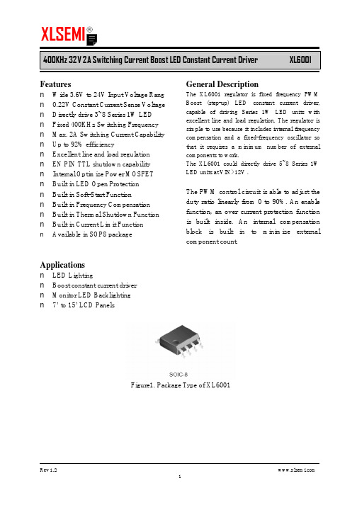
400KHz 32V 2A Switching Current Boost LED Constant Current Driver XL6001Featuresn Wide 3.6V to 24V Input Voltage Rang n0.22V Constant Current Sense Voltage n Directly drive 3~8 Series 1W LEDn Fixed 400KHz Switching Frequency n Max. 2A Switching Current Capability n Up to 92% efficiencyn Excellent line and load regulationn EN PIN TTL shutdown capabilityn Internal Optimize Power MOSFETn Built in LED Open Protectionn Built in Soft-Start Functionn Built in Frequency Compensationn Built in Thermal Shutdown Function n Built in Current Limit Functionn Available in SOP8 package Applicationsn LED Lightingn Boost constant current drivern Monitor LED Backlightingn7’ to 15’ LCD Panels General DescriptionThe XL6001 regulator is fixed frequency PWM Boost (step-up) LED constant current driver, capable of driving Series 1W LED units with excellent line and load regulation. The regulator is simple to use because it includes internal frequency compensation and a fixed-frequency oscillator so that it requires a minimum number of external components to work.The XL6001 could directly drive 5~8 Series 1W LED units at VIN>12V .The PWM control circuit is able to adjust the duty ratio linearly from 0 to 90%. An enable function, an over current protection function is built inside. An internal compensation block is built in to minimize external component count.Figure1. Package Type of XL6001400KHz 32V 2A Switching Current Boost LED Constant Current DriverXL6001Pin ConfigurationsSWEN FB VIN NCSW GNDGNDFigure2. Pin Configuration of XL6001 (Top View)Table 1 Pin DescriptionPin NumberPin Name Description1 ENEnable Pin. Drive EN pin low to turn off the device, drive ithigh to turn it on. Floating is default high.2 VINSupply V oltage Input Pin. XL6001 operates from a 3.6V to 24V DC voltage. Bypass Vin to GND with a suitably large capacitor to eliminate noise on the input.3 FB Feedback Pin (FB). The feedback threshold voltage is 0.22V .4 NC No Connected.5,6 SWPower Switch Output Pin (SW). Output is the switch node thatsupplies power to the output.7,8 GND Ground Pin.400KHz 32V 2A Switching Current Boost LED Constant Current Driver XL6001 Function BlockFigure3. Function Block Diagram of XL6001Typical Application CircuitFigure4. XL6001 Typical Application Circuit400KHz 32V 2A Switching Current Boost LED Constant Current Driver XL6001Ordering InformationPart Number Marking ID Lead Free Lead Free Packing Type XL6001E1 XL6001E1 Tube PackageTemperature RangeXL6001TRE1XL6001E1Tape & ReelXLSEMI Pb-free products, as designated with “E1” suffix in the par number, are RoHS compliant.Absolute Maximum Ratings (Note1)ParameterSymbol Value Unit Input VoltageVin -0.3 to 26 V Feedback Pin Voltage V FB -0.3 to Vin V EN Pin VoltageV EN -0.3 to Vin V Output Switch Pin Voltage V Output -0.3 to 32 V Power DissipationP D Internally limitedmW Thermal Resistance (SOP8)(Junction to Ambient, No Heatsink, Free Air) R JA 100 ºC/W Operating Junction Temperature T J -40 to 125 ºC Storage TemperatureT STG -65 to 150 ºC Lead Temperature (Soldering, 10 sec) T LEAD 260 ºC ESD (HBM)>2000VNote1: Stresses greater than those listed under Maximum Ratings may cause permanent damage to the device. This is a stress rating only and functional operation of the device at these or any other conditions above those indicated in the operation is not implied. Exposure to absolute maximum rating conditions for extended periods may affect reliability.400KHz 32V 2A Switching Current Boost LED Constant Current Driver XL6001 XL6001 Electrical CharacteristicsT a = 25℃;unless otherwise specified.Symbol Parameter Test Condition Min. Typ. Max. Unit System parameters test circuit figure4VFB FeedbackV oltageVin = 5V to 12V, V out=24VIload=100mA209 220 231 mVEfficiency ŋVin=12V ,V out= 6*1W LEDIout=0.3A- 92 - %Electrical Characteristics (DC Parameters)Vin = 12V, GND=0V, Vin & GND parallel connect a 47uf/25V capacitor; Iout=50mA, T a = 25℃; the others floating unless otherwise specified.Parameters Symbol Test Condition Min. Typ. Max. Unit Input operation voltage Vin 3.6 24 V Shutdown Supply Current I STBY V EN=0V 70 100 uAQuiescent Supply Current I q V EN =2V,V FB =Vin2.5 5 mAOscillator Frequency Fosc 320 400 480 Khz Switch Current Limit I L V FB =0 2 AOutput Power NMOS Rdson Vin=12V,I SW=2A110 120 mohmEN Pin Threshold V EN High (Regulator ON)Low (Regulator OFF)1.40.8VI H V EN =2V (ON) 3 10 uA EN Pin Input LeakageCurrent ILV EN =0V (OFF) 3 10 uA Max. Duty Cycle D MAX V FB=0V 90 %400KHz 32V 2A Switching Current Boost LED Constant Current Driver XL6001Schottky Diode Selection TableCurrent SurfaceMountThrough Hole VR (The same as system maximum input voltage)20V 30V 40V 50V60V1A √1N5817 1N5818 1N5819√ 1N5820 1N5821 1N5822√ MBR320 MBR330 MBR340 MBR350 MBR360 √ SK32 SK33 SK34SK35SK36 √ 30WQ03 30WQ04 30WQ05 √ 31DQ03 31DQ04 31DQ05 3A√SR302SR303SR304SR305SR306Typical System Application for VIN=5V to driver 2~6 x 1W series LED unitsFigure5. XL6001 System Parameters Test Circuit (2~6 x 1W LED)400KHz 32V 2A Switching Current Boost LED Constant Current Driver XL6001 Typical System Application for VIN=12V to driver 4~8 x 1W series LED unitsFigure6. XL6001 System Parameters Test Circuit (4~8 x 1W LED)Typical System Application for VIN=12V to driver 4~8 x 1W series LED units With PWM DimmingFigure7. XL6001 System Parameters Test Circuit (4~8 x 1W LED with PWM Dimming)400KHz 32V 2A Switching Current Boost LED Constant Current Driver XL6001 Typical System Application for SEPIC Buck-Boost LED DriverFigure8. XL6001 System Parameters Test Circuit (Buck-Boost LED Driver)400KHz 32V 2A Switching Current Boost LED Constant Current Driver XL6001 Package InformationSOP8 Package Mechanical Dimensions。
XL4016原厂规格书(2014版)

8A 180KHz 40V Buck DC to DC Converter XL4016Featuresn Wide 8V to 40V Input Voltage Range n Output Adjustable from 1.25V to 36V n Maximum Duty Cycle 100%n Minimum Drop Out 0.3Vn Fixed 180KHz Switching Frequencyn8A Constant Output Current Capability n Internal Optimize Power MOSFETn High efficiency up to 96%n Excellent line and load regulationn Built in thermal shutdown functionn Built in current limit functionn Built in output short protection function n Built in input over voltage protection n Available in TO220-5L package Applicationsn LCD Monitor and LCD TVn Portable instrument power supplyn Telecom / Networking Equipment General DescriptionThe XL4016 is a 180 KHz fixed frequency PWM buck (step-down) DC/DC converter, capable of driving a 8A load with high efficiency, low ripple and excellent line and load regulation. Requiring a minimum number of external components, the regulator is simple to use and include internal frequency compensation and a fixed-frequency oscillator.The PWM control circuit is able to adjust the duty ratio linearly from 0 to 100%. An over current protection function is built inside. When short protection function happens, the operation frequency will be reduced from 180KHz to 48KHz. An internal compensation block is built in to minimize external component count.Figure1. Package Type of XL40168A 180KHz 40V Buck DC to DC ConverterXL4016Pin ConfigurationsFigure2. Pin Configuration of XL4016 (Top View) Table 1 Pin DescriptionPin Number Pin Name Description1 GND Ground Pin. Care must be taken in layout. This pin should be placed outside of the Schottky Diode to output capacitor ground path to prevent switching current spikes from inducing voltage noise into XL4016.2 FB Feedback Pin (FB). Through an external resistor divider network, FB senses the output voltage and regulates it. The feedback threshold voltage is 1.25V.3 SW Power Switch Output Pin (SW). SW is the switch node that supplies power to the output.4 VC Internal V oltage Regulator Bypass Capacity. In typical system application, The VC pin connect a 1uf capacity to VIN.5 VIN Supply V oltage Input Pin. XL4016 operates from a 8V to 40V DC voltage. Bypass Vin to GND with a suitably large capacitor to eliminate noise on the input.8A 180KHz 40V Buck DC to DC Converter XL4016 Function BlockFigure3. Function Block Diagram of XL4016Typical Application CircuitFigure4. XL4016 Typical Application Circuit (VIN=8V~40V, VOUT=5V/8A)8A 180KHz 40V Buck DC to DC Converter XL4016 Ordering InformationPart Number Marking ID Lead Free Lead Free Packing TypePackage TemperatureRangeXL4016E1 XL4016E1 TubeXLSEMI Pb-free products, as designated with “E1” suffix in the par number, are RoHS compliant.Absolute Maximum Ratings(Note1)Parameter Symbol Value Unit Input Voltage Vin -0.3 to 45 V Feedback Pin Voltage V FB-0.3 to Vin V Output Switch Pin Voltage V Output-0.3 to Vin V Power Dissipation P D Internally limited mW Thermal Resistance (TO220-5L)(Junction to Ambient, No Heatsink, Free Air)R JA30 ºC/W Operating Junction Temperature T J-40 to 125 ºC Storage Temperature T STG-65 to 150 ºC Lead Temperature (Soldering, 10 sec) T LEAD260 ºC ESD (HBM) >2000 V Note1: Stresses greater than those listed under Maximum Ratings may cause permanent damage to the device. This is a stress rating only and functional operation of the device at these or any other conditions above those indicated in the operation is not implied. Exposure to absolute maximum rating conditions for extended periods may affect reliability.8A 180KHz 40V Buck DC to DC Converter XL4016 XL4016 Electrical CharacteristicsT a = 25℃;unless otherwise specified.Symbol Parameter Test Condition Min. Typ. Max. Unit System parameters test circuit figure4VFB FeedbackV oltageVin = 8V to 40V, V out=5VIload=0.5A to 8A1.225 1.25 1.275 VEfficiency ŋVin=12V ,V out=5VIout=6A- 87 - %Efficiency ŋVin=24V ,V out=12VIout=6A- 93 - %Electrical Characteristics (DC Parameters)Vin = 12V, GND=0V, Vin & GND parallel connect a 470uf/50V capacitor; Iout=500mA, T a = 25℃; the others floating unless otherwise specified.Parameters Symbol Test Condition Min. Typ. Max. Unit Input operation voltage Vin 8 40 V Quiescent Supply Current I q V FB =Vin 2.1 5 mA Oscillator Frequency Fosc 144 180 216 KHz Output Short Frequency Fosp 48 KHz Switch Current Limit I L V FB =0 10 A Max. Duty Cycle D MAX V FB=0V 100 %Output Power PMOS Rdson V FB=0V, Vin=12V,I SW=8A40 50 mohmVin Over V oltage Protection OVP 45 V8A 180KHz 40V Buck DC to DC ConverterXL4016Typical System Application (VOUT=5V/8A)Figure5. XL4016 System Parameters Test Circuit (VIN=8V~40V, VOUT=5V/8A)50556065707580859095100Efficiency VS Load currentE f f i c i e n c y (%)Load current(A)Figure6. XL4016 System Efficiency Curve8A 180KHz 40V Buck DC to DC ConverterXL4016Typical System Application (VOUT=12V/6A)Figure7. XL4016 System Parameters Test Circuit (VIN=15V~40V, VOUT=12V/6A)0.00.51.01.52.02.53.03.54.04.55.05.56.050556065707580859095100Efficiency VS Load currentE f f i c i e n c y (%)Load current(A)Figure8. XL4016 System Efficiency Curve8A 180KHz 40V Buck DC to DC Converter XL4016Typical System Application (With Enable function)Logic level signal shutdown function can be used in typical system application with external components. When the TTL high voltage above 3.3V(referenced to ground, lower than VIN), the converter will shutdown, input current less than 3mA;when the TTL Low voltage below 0.8V(referenced to ground), the converter will turn on.L1 47uH/12AFigure9. XL4016 Typical Application Circuit with Enable Function8A 180KHz 40V Buck DC to DC Converter XL4016Package InformationTO220-5L。
XL1410原厂规格书(2014版)

Rev 1.0
Figure1. Package Type of XL1410
1
2A 380KHz 18V Buck DC to DC Converter
XL1410
Pin Configurations
NC 1
8 NC
VIN 2
7 EN
XL1410
SW 3
6 NC
GND 4
Vin = 12V, GND=0V, Vin & GND parallel connect a 220uf/50V capacitor; Iout=500mA, Ta = 25℃; the others floating unless otherwise specified.
Parameters
Symbol
LCD Monitor and LCD TV Digital Photo Frame Set-up Box ADSL Modem Telecom / Networking Equipment
General Description
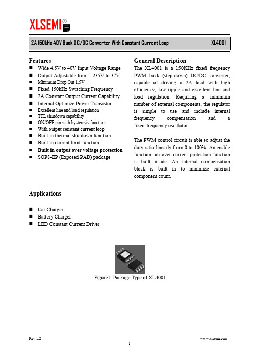
The XL1410 is a 380KHz fixed frequency PWM buck (step-down) DC/DC converter, capable of driving a 2A load with high efficiency, low ripple and excellent line and load regulation. Requiring a minimum number of external components, the regulator is simple to use and include internal frequency compensation and a fixed-frequency oscillator.
XL4001原厂规格书(2014版)
1N5821 MBR330 SK33 30WQ03 31DQ03 SR303
+6V~36V
EN
FB
VIN
7,8
4 XL4001
6 1,2
SW
3
5
GND
CS
CIN
C1
100uf/50V 105
L 33uh
D1 1N5821 COUT
100uf/35V
VOUT
R2
LED 1W~5W
R1 1K Rcs
Figure5. XL4001 Typical Application Circuit (LED Constant Current Driver)
Absolute Maximum Ratings(Note1)
Parameter
Symbol
Value
Unit
Input Voltage
Vin
-0.3 to 45
V
FB Pin Voltage EN Pin Voltage
VFB
-0.3 to Vin
V
VEN
-0.3 to Vin
V
SW Pin Voltage
1.21 1.235 1.26 V
-
83
-
%
Electrical Characteristics (DC Parameters)
Vin = 12V, GND=0V, Vin & GND parallel connect a 220uf/50V capacitor; Iout=500mA, Ta = 25℃; the others floating unless otherwise specified.
华大驱动器说明书-中文
3.1 模块及按键功能................................................................................................................... 22 3.1.1 模块 22 3.1.2 按键功能............................................................. 22 3.2.1 监视模式 ............................................................. 23 3.2.2 监视模式说明 ......................................................... 24
1.1 铭牌......................................................................................................................................... 6
1.2 驱动器型号说明..................................................................................................................... 6
3.3 参数设置.................................................................................................................................... 24 3.3.1 参数设置 ............................................................. 24 3.3.2 辅助功能 ............................................................. 25
XL使用说明书
a.检查漆膜有无剥落,屏内是否清洁。
b.操作机构是否灵活,不应有卡住或操作力过大现象。
c.主要电器的通断是否可靠准确。
d.电器的辅助接点的通断是否可靠准确。
e.仪表与互感器的接线极性是否正确。
f.母线连接是否良好,其支持绝缘子、夹持件及附件是否安装牢固可靠。
9.2按所选方案的电气原理图,列出电器元件明细表,标出电器元件型号及具体的技术数据。
9.3配电柜数量及运行时的排列顺序图。
9.4配电柜的进出线方式。
附产品外形及安装尺寸。
XL动力配电柜
ZCKJ/QS-026.2-2005
安装使用说明书
共3页
第2页
6.结构
6.1本产品系户内用户安装,具有开启式单、双(单)面维护的低压配电装置。
a.其基本结构采用型材组合或型钢焊接而成。
b.柜前有门,柜面上方有仪表门,可装指示仪表,因此维修方便。
c.组合并列拼装的柜,柜与柜之间架有钢板弯制而成的隔板,这样就减少了单柜内故障扩大的可能性。
2.型号编制说明
XL–□-□-□
辅助电路方案号
主电路方案号
设计序号
动力配电柜
3.正常使用条件
3.1周围环境温度不高于+40℃,而在24h周期内平均温度不高于+35℃,周围空气温度的下限为-5℃。
3.2相对湿度在最高温度为+40℃时,不超过50%;在温度较低时,允许有较高的相对湿度,例如:+20℃时为90%。
5主要技术参数
5.1绝缘电压660V
5.2主电路额定工作电压AC380V
主电路额定工作电流Ie≤400A
5.3辅助电路额定工作电压为AC220V、380V;DC110V、220V。
PAM8404规格书

Supply Voltage............................................6.0V Input Voltage.............................-0.3V to V + DD 0.3V
Maximum Junction Temperature..................150°C Storage Temperature.....................-65°C to 150°C Soldering Temperature....................250°C,10 sec
Total Harmonic Distortion Plus THD+N
Noise
Power Supply Ripple Rejection
PSRR
THD+N=1% f=1kHz RL=8Ω
VDD=5.0V,Po=0.5W,RL=8Ω VDD=3.6V,Po=0.5W,RL=8Ω VDD=5.0V,Po=1W,RL=4Ω VDD=3.6V,Po=1W,RL=4Ω VDD=5.0V, Inputs ac-grounded with Cin=1μF
VDD=5V VDD=3.6V f=1kHz
f=1kHz f=100Hz f=1kHz
SN74ALS869DWE4,SN74AS867DW,SN74AS867DWE4,SN74AS869DW,SN74AS869DWE4, 规格书,Datasheet 资料

Addendum-Page 1PACKAGING INFORMATIONOrderable Device Status(1)Package Type PackageDrawingPins Package QtyEco Plan(2)Lead/Ball Finish MSL Peak Temp (3)Samples (Requires Login)5962-89526013A ACTIVE LCCC FK 281TBD Call TI Call TI 5962-8952601KA ACTIVE CFP W 241TBD Call TI Call TI 5962-8952601LA ACTIVE CDIP JT 241TBD Call TI Call TI 5962-89668013A ACTIVE LCCC FK 281TBD Call TI Call TI 5962-8966801KA ACTIVE CFP W 241TBD Call TI Call TI 5962-8966801LA ACTIVE CDIP JT 241TBD Call TI Call TISN54AS867JT ACTIVE CDIP JT 241TBD A42N / A for Pkg Type SN54AS869JT ACTIVE CDIP JT 241TBDA42N / A for Pkg TypeSN74ALS867ADW ACTIVE SOIC DW 2425Green (RoHS & no Sb/Br)CU NIPDAU Level-1-260C-UNLIM SN74ALS867ADWE4ACTIVE SOIC DW 2425Green (RoHS & no Sb/Br)CU NIPDAU Level-1-260C-UNLIM SN74ALS867ADWG4ACTIVE SOIC DW 2425Green (RoHS & no Sb/Br)CU NIPDAU Level-1-260C-UNLIM SN74ALS867ANT ACTIVE PDIP NT 2415Pb-Free (RoHS)CU NIPDAU N / A for Pkg Type SN74ALS867ANTE4ACTIVE PDIP NT 2415Pb-Free (RoHS)CU NIPDAU N / A for Pkg Type SN74ALS869DW ACTIVE SOIC DW 2425Green (RoHS & no Sb/Br)CU NIPDAU Level-1-260C-UNLIM SN74ALS869DWE4ACTIVE SOIC DW 2425Green (RoHS & no Sb/Br)CU NIPDAU Level-1-260C-UNLIM SN74ALS869DWG4ACTIVE SOIC DW 2425Green (RoHS & no Sb/Br)CU NIPDAU Level-1-260C-UNLIM SN74ALS869NT ACTIVE PDIP NT 2415Pb-Free (RoHS)CU NIPDAU N / A for Pkg Type SN74ALS869NTE4ACTIVE PDIP NT 2415Pb-Free (RoHS)CU NIPDAU N / A for Pkg Type SN74AS867DW ACTIVE SOIC DW 2425Green (RoHS & no Sb/Br)CU NIPDAU Level-1-260C-UNLIM SN74AS867DWE4ACTIVE SOIC DW 2425Green (RoHS & no Sb/Br)CU NIPDAU Level-1-260C-UNLIM SN74AS867DWG4ACTIVE SOIC DW 2425Green (RoHS & no Sb/Br)CU NIPDAU Level-1-260C-UNLIM SN74AS867NT ACTIVE PDIP NT 2415Pb-Free (RoHS)CU NIPDAU N / A for Pkg Type SN74AS867NT3OBSOLETEPDIPNT24TBDCall TICall TI芯天下--/Addendum-Page 2Orderable Device Status(1)Package Type PackageDrawingPins Package QtyEco Plan(2)Lead/Ball FinishMSL Peak Temp(3)Samples (Requires Login)SN74AS867NTE4ACTIVE PDIP NT 2415Pb-Free (RoHS)CU NIPDAU N / A for Pkg Type SN74AS869DW ACTIVE SOIC DW 2425Green (RoHS & no Sb/Br)CU NIPDAU Level-1-260C-UNLIM SN74AS869DWE4ACTIVE SOIC DW 2425Green (RoHS & no Sb/Br)CU NIPDAU Level-1-260C-UNLIM SN74AS869DWG4ACTIVE SOIC DW 2425Green (RoHS & no Sb/Br)CU NIPDAU Level-1-260C-UNLIM SN74AS869NT ACTIVE PDIP NT 2415Pb-Free (RoHS)CU NIPDAU N / A for Pkg Type SN74AS869NT3OBSOLETE PDIP NT 24TBD Call TICall TISN74AS869NTE4ACTIVE PDIP NT 2415Pb-Free (RoHS)CU NIPDAU N / A for Pkg Type SNJ54AS867FK ACTIVE LCCC FK 281TBD POST-PLATE N / A for Pkg TypeSNJ54AS867JT ACTIVE CDIP JT 241TBD A42N / A for Pkg Type SNJ54AS867W ACTIVE CFP W 241TBD A42N / A for Pkg Type SNJ54AS869FK ACTIVE LCCC FK 281TBD POST-PLATE N / A for Pkg TypeSNJ54AS869JT ACTIVE CDIP JT 241TBD A42N / A for Pkg Type SNJ54AS869WACTIVECFPW241TBDA42N / A for Pkg Type(1)The marketing status values are defined as follows:ACTIVE: Product device recommended for new designs.LIFEBUY: TI has announced that the device will be discontinued, and a lifetime-buy period is in effect.NRND: Not recommended for new designs. Device is in production to support existing customers, but TI does not recommend using this part in a new design.PREVIEW: Device has been announced but is not in production. Samples may or may not be available.OBSOLETE: TI has discontinued the production of the device.(2)Eco Plan - The planned eco-friendly classification: Pb-Free (RoHS), Pb-Free (RoHS Exempt), or Green (RoHS & no Sb/Br) - please check /productcontent for the latest availability information and additional product content details.TBD: The Pb-Free/Green conversion plan has not been defined.Pb-Free (RoHS): TI's terms "Lead-Free" or "Pb-Free" mean semiconductor products that are compatible with the current RoHS requirements for all 6 substances, including the requirement that lead not exceed 0.1% by weight in homogeneous materials. Where designed to be soldered at high temperatures, TI Pb-Free products are suitable for use in specified lead-free processes.Pb-Free (RoHS Exempt): This component has a RoHS exemption for either 1) lead-based flip-chip solder bumps used between the die and package, or 2) lead-based die adhesive used between the die and leadframe. The component is otherwise considered Pb-Free (RoHS compatible) as defined above.Green (RoHS & no Sb/Br): TI defines "Green" to mean Pb-Free (RoHS compatible), and free of Bromine (Br) and Antimony (Sb) based flame retardants (Br or Sb do not exceed 0.1% by weight in homogeneous material)(3)MSL, Peak Temp. -- The Moisture Sensitivity Level rating according to the JEDEC industry standard classifications, and peak solder temperature.芯天下--/Important Information and Disclaimer:The information provided on this page represents TI's knowledge and belief as of the date that it is provided. TI bases its knowledge and belief on information provided by third parties, and makes no representation or warranty as to the accuracy of such information. Efforts are underway to better integrate information from third parties. TI has taken and continues to take reasonable steps to provide representative and accurate information but may not have conducted destructive testing or chemical analysis on incoming materials and chemicals. TI and TI suppliers consider certain information to be proprietary, and thus CAS numbers and other limited information may not be available for release.In no event shall TI's liability arising out of such information exceed the total purchase price of the TI part(s) at issue in this document sold by TI to Customer on an annual basis.OTHER QUALIFIED VERSIONS OF SN54AS867, SN54AS869, SN74AS867, SN74AS869 :•Catalog: SN74AS867, SN74AS869•Military: SN54AS867, SN54AS869NOTE: Qualified Version Definitions:•Catalog - TI's standard catalog product•Military - QML certified for Military and Defense ApplicationsAddendum-Page 3芯天下--/IMPORTANT NOTICETexas Instruments Incorporated and its subsidiaries(TI)reserve the right to make corrections,modifications,enhancements,improvements, and other changes to its products and services at any time and to discontinue any product or service without notice.Customers should obtain the latest relevant information before placing orders and should verify that such information is current and complete.All products are sold subject to TI’s terms and conditions of sale supplied at the time of order acknowledgment.TI warrants performance of its hardware products to the specifications applicable at the time of sale in accordance with TI’s standard warranty.Testing and other quality control techniques are used to the extent TI deems necessary to support this warranty.Except where mandated by government requirements,testing of all parameters of each product is not necessarily performed.TI assumes no liability for applications assistance or customer product design.Customers are responsible for their products and applications using TI components.To minimize the risks associated with customer products and applications,customers should provide adequate design and operating safeguards.TI does not warrant or represent that any license,either express or implied,is granted under any TI patent right,copyright,mask work right, or other TI intellectual property right relating to any combination,machine,or process in which TI products or services are rmation published by TI regarding third-party products or services does not constitute a license from TI to use such products or services or a warranty or endorsement e of such information may require a license from a third party under the patents or other intellectual property of the third party,or a license from TI under the patents or other intellectual property of TI.Reproduction of TI information in TI data books or data sheets is permissible only if reproduction is without alteration and is accompanied by all associated warranties,conditions,limitations,and notices.Reproduction of this information with alteration is an unfair and deceptive business practice.TI is not responsible or liable for such altered rmation of third parties may be subject to additional restrictions.Resale of TI products or services with statements different from or beyond the parameters stated by TI for that product or service voids all express and any implied warranties for the associated TI product or service and is an unfair and deceptive business practice.TI is not responsible or liable for any such statements.TI products are not authorized for use in safety-critical applications(such as life support)where a failure of the TI product would reasonably be expected to cause severe personal injury or death,unless officers of the parties have executed an agreement specifically governing such use.Buyers represent that they have all necessary expertise in the safety and regulatory ramifications of their applications,and acknowledge and agree that they are solely responsible for all legal,regulatory and safety-related requirements concerning their products and any use of TI products in such safety-critical applications,notwithstanding any applications-related information or support that may be provided by TI.Further,Buyers must fully indemnify TI and its representatives against any damages arising out of the use of TI products in such safety-critical applications.TI products are neither designed nor intended for use in military/aerospace applications or environments unless the TI products are specifically designated by TI as military-grade or"enhanced plastic."Only products designated by TI as military-grade meet military specifications.Buyers acknowledge and agree that any such use of TI products which TI has not designated as military-grade is solely at the Buyer's risk,and that they are solely responsible for compliance with all legal and regulatory requirements in connection with such use. TI products are neither designed nor intended for use in automotive applications or environments unless the specific TI products are designated by TI as compliant with ISO/TS16949requirements.Buyers acknowledge and agree that,if they use any non-designated products in automotive applications,TI will not be responsible for any failure to meet such requirements.Following are URLs where you can obtain information on other Texas Instruments products and application solutions:Products ApplicationsAudio /audio Communications and Telecom /communicationsAmplifiers Computers and Peripherals /computersData Converters Consumer Electronics /consumer-appsDLP®Products Energy and Lighting /energyDSP Industrial /industrialClocks and Timers /clocks Medical /medicalInterface Security /securityLogic Space,Avionics and Defense /space-avionics-defense Power Mgmt Transportation and Automotive /automotiveMicrocontrollers Video and Imaging /videoRFID OMAP Mobile Processors /omapWireless Connctivity /wirelessconnectivityTI E2E Community Home Page Mailing Address:Texas Instruments,Post Office Box655303,Dallas,Texas75265Copyright©2011,Texas Instruments Incorporated。
浪潮英信服务器NF5280M4用户手册V1.0
③ Los ajustes de BIOS y BMC son muy importantes. Si no hay requisitos especiales, por favor, utilice la configuración por defecto del sistema y no cambie los parámetros de la configuración.
① Please do not disassemble the server’s components arbitrarily. Please do not extend configuration or connect other peripheral devices arbitrarily. If needed, please be sure to conduct it with our authorization and guidance.
本指南认定读者对服务器产品有足够的认识,获得了足够的培训,在操作、维护过程中 不会造成个人伤害或产品损坏。
目标受众
本手册主要适用于以下人员: ● 技术支持工程师 ● 产品维护工程师 建议由具备服务器知识的专业工程师参考本手册进行服务器运维操作。
警告:
本手册介绍了此款服务器的技术特性与系统的设置、安装,有助于您更详细的了解和便 捷地使用此款服务器。
浪潮 2014 年 11 月
和“英信”是浪潮集团有限公司的注册商标。 本手册中提及的其他所有商标或注册商标,由各自的所有人拥有。
XL2576原厂规格书(2014版)
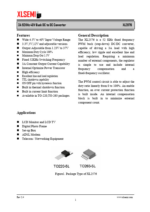
Built in thermal shutdown function Built in current limit function Available in TO-220,TO-263 packages
Applications
n n n n n LCD Monitor and LCD TV Digital Photo Frame Set-up Box ADSL Modem Telecom / Networking Equipment
Rev 2.4 3
3A 52KHz 40V Buck DC to DC Converter Ordering Information XL2576 E1
E1: Lead Fr263-5L T: TO220-5L
XL2576
4 5
Rev 2.4 2
3A 52KHz 40V Buck DC to DC Converter Function Block
XL2576
Figure3. Function Block Diagram of XL2576
Typical Application Circuit
Rev 2.4 5
3A 52KHz 40V Buck DC to DC Converter XL2576-3.3 Electrical Characteristics
Ta = 25℃;unless otherwise specified. Symbol Parameter Test Condition Min. Typ.
XLSEMI Pb-free products, as designated with “ E1” suffix in the par number, are RoHS compliant.
8004 8008 钳表 说明书

8008中文说明书特长MODEL 8004和8008配合钳表使用时,可测量小型钳表无法测量的大直径导体和大电流。
规格MODEL 8004 MODEL 8008测量范围0-1000A AC 0-3000A AC分流比 10:1 10:1精确度输入的±3%±0.5A 输入的±2%±0.5A耐电压 3000VAC/分钟 3000VAC/分钟尺寸本体240×85×10mm拾取环40×45×10mm 本体310×150×30mm 拾取环40×45×10mm重量约490g 约750g可测量导体直径最大直径60mm。
80×55mm母线最大直径60mm。
80×55mm母线频率50/60Hz 50/60Hz可测量时间连续 0-1000A连续1000-1500A 10分钟3000A 30秒测量方法1.如图所示,钳表夹住MODEL 8008的拾取环后将8008夹在被测导体上。
钳表显示的数据乘以10即为测量结果。
2.使用MODEL8008测量功率时,可通过拾取环和钳口上的箭头标志判断电源端和负荷端。
钳表夹住MODEL 8008的拾取环,拾取环上的箭头指向负荷端。
然后夹住被测导体,钳口上的箭头指向导体负荷端。
箭头标志被测导体钳口箭头标志拾取环 钳表MODEL 8008克列茨国际贸易(上海)有限公司上海市浦东新区张杨路1518号404室电话:************传真:************网址: 邮箱:****************.cn。
60065(2014版)标准-说明书
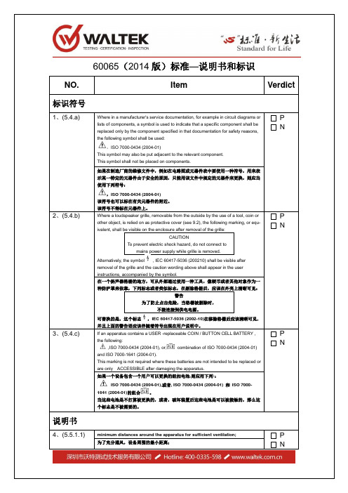
60065(2014版)标准—说明书和标识NO.Item Verdict 标识符号1、(5.4.a) Where in a manufacturer's service documentation, for example in circuit diagrams orlists of components, a symbol is used to indicate that a specific component shall bereplaced only by the component specified in that documentation for safety reasons,the following symbol shall be used:,ISO 7000-0434 (2004-01)This symbol may also be put adjacent to the relevant component.This symbol shall not be placed on components.P N如果在制造厂商的维修文件中,例如在电路图或元器件表中要使用一种符号,用来表示某一特定的元器件由于安全的原因,只能用该文件中规定的元器件来更换,则应当使用下列符号:,ISO 7000-0434 (2004-01)该符号也可以标在有关元器件的附近。
该符号不得标在元器件上。
2、(5.4.b) Where a loudspeaker grille, removable from the outside by the use of a tool, coin orother object, is relied on as protective cover (see 9.2), the following marking, or equ-ivalent, shall be visible on the enclosure after removal of the grille:CAUTIONTo prevent electric shock hazard, do not connect tomains power supply while grille is removed.Alternatively, the symbol , IEC 60417-5036 (200210) shall be visible after removal of the grille and the caution wording above shall appear in the userinstructions, accompanied by the symbol.P N在一个扬声器格栅的地方,可从外部通过使用一种工具,像硬币或者其他对象作为一种防护罩来依靠,下列标志或者类似标志,在删除格栅后,应该在外壳上清晰可见:警告为了防止点击危险,当格栅被删除时,不能连接到供电电源。
- 1、下载文档前请自行甄别文档内容的完整性,平台不提供额外的编辑、内容补充、找答案等附加服务。
- 2、"仅部分预览"的文档,不可在线预览部分如存在完整性等问题,可反馈申请退款(可完整预览的文档不适用该条件!)。
- 3、如文档侵犯您的权益,请联系客服反馈,我们会尽快为您处理(人工客服工作时间:9:00-18:30)。
80V 1A Switching Current Buck PFM LED Constant Current Driver XL8004Featuresn Wide 24V to 80V Input Voltage Range n0.2V current sense voltage reference. n Directly drive 3~8 series LED.n Excellent line and load regulation.n High efficiency up to 96%.n Internal optimize power HV-MOSFET. n Built in thermal shutdown function.n Built in UVLO function.n Built in current limiting function.n Built in LED open & short protection. n Built in soft-start circuit.n Available in TO252-5L package. Applicationsn EBIKE LED Lightingn LED Lighting & LED LAMPn General purpose lighting General DescriptionThe XL8004 is a monolithic high voltage switching regulator with PFM that is specifically designed to operate from a 24V~80V DC supply.The XL8004 is a high efficiency LED driver switching regulator. The LED string is driven at DC constant current rather than constant voltage, thus providing constant current output and enhanced reliability.Figure1. Package Type of XL800480V 1A Switching Current Buck PFM LED Constant Current Driver XL8004 Pin ConfigurationsFigure2. Pin Configuration of XL8004 (Top View)Table 1 Pin DescriptionPin Number Pin Name Description1 VDD The chip supply voltage.2 CSN Current Sense Negative Terminal.3 VIN Input high voltage Pin. (Operation voltage 24V~ 80V)4 CSP Current Sense Positive Terminal.5 SW Output Switching Pin.Function BlockFigure3. Function Block Diagram of XL800480V 1A Switching Current Buck PFM LED Constant Current Driver XL8004 Typical application circuitFigure4. XL8004 Typical Application (3W~8W LED lamp)Ordering InformationOrder Information Marking ID Package Type Packing Type Supplied AsXL8004E1 XL8004E1 TO252-5L 2500 Units on Tape & ReelAbsolute Maximum Ratings(Note1)Parameter Symbol Value Unit Input Voltage Vin -0.3 to 90 V Power Dissipation P D Internally limited mW Thermal Resistance (TO252-5L)R JA50 ºC/W (Junction to Ambient, No Heatsink, Free Air)Operating Junction Temperature T J-40 to 125 ºC Storage Temperature T STG-65 to 150 ºC Lead Temperature (Soldering, 10 sec) T LEAD260 ºC ESD (HBM) 3000 V80V 1A Switching Current Buck PFM LED Constant Current Driver XL8004 Note1: Stresses greater than those listed under Maximum Ratings may cause permanent damage to the device. This is a stress rating only and functional operation of the device at these or any other conditions above those indicated in the operation is not implied. Exposure to absolute maximum rating conditions for extended periods may affect reliability.XL8004 Electrical CharacteristicsT a = 25℃;unless otherwise specified. Reference test circuit figure4Symbol Parameter Test Condition Min. Typ. Max. UnitVCSPCSPV oltageVIN = 24V to 80V,Iled=0.3A, Pout=8W190 200 210 mVEfficiency ŋVIN=48V, Iled=0.3A, Pout=8W - 94.9 - % Efficiency ŋVIN=60V, Iled=0.3A, Pout=8W - 94.6 - % Efficiency ŋVIN=72V, Iled=0.3A, Pout=8W - 92.4 - %Electrical Characteristics (DC Parameters)Parameters Symbol Test Condition Min. Typ. Max. Unit Input operation voltage VIN 24 80 VSwitching Frequency Fosc Figure4 (8*1W)VIN=48V47.8 59.7 71.6 KHzSwitching Frequency Fosc Figure4 (8*1W)VIN=60V56.5 70.6 84.7 KHzSwitching Frequency Fosc Figure4 (8*1W)VIN=72V61.2 76.4 91.6 KHzOutput LED open voltage V open Figure4 VIN=72V 36 V DMOS Drain-SourceBreakdown V oltageV BRDS V GS=0V, I DS=250uA 90 V DMOSDrain-Source on resistorR DSON I DS=0.5A, V GS=10V 0.1 0.15 Ohm Thermal Shutdown OTP Tj 165 0C Thermal Shutdown Window 25 0C80V 1A Switching Current Buck PFM LED Constant Current Driver XL8004 [1] Typical application circuit (3W ~ 8W)Figure5. XL8004 System Application (3W ~ 8W)The figure5 system parameters as following:VIN=36V DC1W LED Series Vin(V) Iin(mA) Vout(V) Iout(mA) Fosc(KHz) Effiency(%)3 35.98 88 9.59 300 40.1 90.864 35.97 113 12.75 297 45.5 93.165 35.97 139 16.02 294 48.0 94.206 35.97 163 19.15 290 47.7 94.727 35.96 187 22.33 287 44.4 95.308 35.96 210 25.59 285 38.0 96.58VIN=48V DC1W LED Series Vin(V) Iin(mA) Vout(V) Iout(mA) Fosc(KHz) Effiency(%)3 47.99 67 9.61 305 41.9 91.164 47.99 87 12.76 301 49.6 91.995 47.98 107 16.04 298 55.4 93.116 47.98 125 19.18 295 58.8 94.347 47.98 143 22.36 292 60.2 95.168 47.98 162 25.60 288 59.7 94.8580V 1A Switching Current Buck PFM LED Constant Current Driver XL8004VIN=60V DC1W LED Series Vin(V) Iin(mA) Vout(V) Iout(mA) Fosc(KHz) Effiency(%)3 59.99 56 9.61 310 42.3 88.684 59.98 72 12.78 307 51.2 90.855 59.98 88 16.06 304 58.6 92.506 59.98 103 19.20 300 64.1 93.237 59.98 118 22.39 297 68.2 93.968 59.97 133 25.65 294 70.6 94.55VIN=72V DC1W LED Series Vin(V) Iin(mA) Vout(V) Iout(mA) Fosc(KHz) Effiency(%)3 72.06 49 9.63 315 42.1 85.914 72.05 63 12.80 312 51.6 87.985 72.05 76 16.09 309 60.0 90.806 72.04 89 19.23 305 66.6 91.487 72.04 101 22.42 302 72.0 93.068 72.04 115 25.68 298 76.4 92.37Figure6. XL8004 System efficiency curve80V 1A Switching Current Buck PFM LED Constant Current Driver XL8004 [2] Typical application circuit (6W ~ 16W)Figure7. XL8004 System Application (6W ~ 16W)The figure7 system parameters as following:VIN=36V DC1W LED Series Vin(V) Iin(mA) Vout(V) Iout(mA) Fosc(KHz) Effiency(%) 3*2 35.97 183 9.77 595 22.0 88.314*2 35.96 234 12.99 591 24.7 91.235*2 35.95 286 16.28 586 25.8 92.796*2 35.94 336 19.48 583 25.3 94.057*2 35.94 385 22.70 579 23.2 94.998*2 35.93 433 25.88 575 19.5 95.65VIN=48V DC1W LED Series Vin(V) Iin(mA) Vout(V) Iout(mA) Fosc(KHz) Effiency(%) 3*2 47.98 140 9.78 601 23.4 87.504*2 47.97 179 13.00 597 27.6 90.385*2 47.96 218 16.29 593 30.6 92.396*2 47.96 256 19.49 589 32.3 93.507*2 47.95 294 22.71 585 32.9 94.248*2 47.95 330 25.91 581 32.4 95.1480V 1A Switching Current Buck PFM LED Constant Current Driver XL8004VIN=60V DC1W LED Series Vin(V) Iin(mA) Vout(V) Iout(mA) Fosc(KHz) Effiency(%) 3*2 59.96 115 9.95 609 24.1 87.884*2 59.96 148 13.22 605 29.0 90.135*2 59.96 180 16.53 600 33.0 91.896*2 59.96 211 19.73 596 35.9 92.957*2 59.95 242 22.98 592 38.0 93.778*2 59.95 271 26.18 587 39.0 94.59VIN=72V DC1W LED Series Vin(V) Iin(mA) Vout(V) Iout(mA) Fosc(KHz) Effiency(%) 3*2 72.08 97 9.86 615 24.2 86.734*2 72.07 124 13.12 611 29.4 89.705*2 72.06 151 16.43 606 34.0 91.506*2 72.05 178 19.66 603 37.7 92.447*2 72.04 204 22.90 598 40.7 93.188*2 72.04 229 26.11 594 43.0 94.01Figure8. XL8004 System efficiency curve80V 1A Switching Current Buck PFM LED Constant Current Driver XL8004 [3] Typical application circuit (9W ~ 14W)[1] Input DC 48V~80V.[2] Output Constant Current Drive Series 9~14 * 1W LED.[3] Support Output LED Open & Short Protection.Figure9. XL8004 System Application (9W ~ 14W)The figure9 system parameters as following:VIN=48V DC1W LED Series Vin(V) Iin(mA) Vout(V) Iout(mA) Fosc(KHz) Effiency(%)9 47.99 173 28.69 276 66.8 95.410 47.99 191 31.93 274 61.3 95.411 47.98 207 35.15 272 53.5 96.312 47.97 225 38.41 271 43.1 96.413 47.98 242 41.63 270 30.4 96.8VIN=60V DC1W LED Series Vin(V) Iin(mA) Vout(V) Iout(mA) Fosc(KHz) Effiency(%)9 59.99 141 28.63 278 84.4 94.110 59.99 155 31.88 276 83.8 94.611 59.99 169 35.10 274 81.0 94.912 59.98 183 38.34 272 76.6 95.013 59.98 196 41.58 270 70.5 95.514 59.98 209 44.80 268 62.3 95.880V 1A Switching Current Buck PFM LED Constant Current Driver XL8004VIN=72V DC1W LED Series Vin(V) Iin(mA) Vout(V) Iout(mA) Fosc(KHz) Effiency(%)9 72.04 120 28.61 281 94.4 93.010 72.03 132 31.86 278 96.5 93.211 72.02 143 35.07 276 97.2 94.012 72.02 156 38.33 274 96.4 93.513 72.02 168 41.56 272 94.2 93.414 72.01 180 44.78 269 90.5 92.9Figure10. XL8004 System efficiency curveXLSEMI Datasheet 80V 1A Switching Current Buck PFM LED Constant Current DriverXL8004Rev 1.1 11 Package InformationTO252-5L。
