CST-813G中文资料
S-81337中文资料
Seiko Instruments Inc.
1
易网
HIGH-PRECISION VOLTAGE REGULATOR S-813 Series
Pin Assignment
1. TO-92 1 2 3 VOUT GND VIN 3 2. SOT-89-3 Top view 1 2 3 1
Block Diagram
VIN 3 VREF
+
*
1
VOUT
2 GND * Parasitic diode Figure 1
Applications
• Constant voltage power supply of VTR, camera, OA equipment, cordless phone, and others
Features
• Low current consumption: 16 µA typ. • Small input/output voltage difference (Ex: S-81350HG: 0.12 V typ. IOUT=40 mA) • High accuracy of output voltage: ±2.4% • Wide operating voltage range: 15 V max. • Wide operating temperature range: -30°C to 80°C • TO-92 or SOT-89-3 plastic package
2
Seiko Instruments Inc.
易网
HIGH-PRECISION VOLTAGE REGULATOR S-813 Series
Electrical Characteristics 1. S-81322HG-KW-X
SC813资料

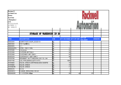
POWER MANAGEMENT Adapter/USB Tri-Mode Single-cell Li-ion ChargerFeaturesSingle input charger with three charging modes Constant voltage — 4.2V, 1% regulationFast-charge current regulation — 15% at 70mA, 9% at 700mACharging by current regulation, voltage regulation, and thermal limitingInput voltage protection — 30VCurrent-limited adapter support capability — reduces power dissipation in charger ICUSB high and low power modes limit charge current to prevent USB Vbus overloadInstantaneous CC-to-CV transition for faster charging Programmable battery-dependent currents (adapter mode fast- and pre-charge, termination)Programmable source-limited currents (USB-high mode fast-charge, and USB-low mode fast- and pre-charge)Independent programming of termination current with dual-mode operation Three termination options — fl oat-charge, automatic re-charge, or forced re-charge to keep the battery topped-off after termination without fl oat-charging Soft-start reduces adapter or USB load transients High operating voltage range of SC811 permits use of unregulated adaptersComplies with CCSA YD/T 1591-2006Space saving 2x2x0.6 (mm) MLPD package WEEE and RoHS compliantApplicationsMobile phones MP3 playersGPS handheld receiversDescriptionThe SC811 and SC813 are highly versatile single input triple mode (adapter/USB high current, USB low current) linear single-cell Li-ion battery chargers, each in an 8 lead 2x2 MLPD ultra-thin package. The input will survive sus-tained input voltage up to 30V to protect against hot plug overshoot and faulty charging adapters. The SC811 has 9.6V rising, 8.2V falling OVP thresholds for general purpose charging with low cost adaptors. The SC813 has 6V rising, 5.6V falling OVP thresholds for customers utilizing charg-ing adapters with specifi cations that are similar to a USB Vbus supply. The SC811 and SC813 differ only in OVP threshold.Charging begins automatically when an input source is applied to the charging input. Thermal limiting protects against excessive power dissipation. The charger can be programmed to turn off when charging is complete or to continue operating as an LDO regulator while fl oat-charg-ing the battery.Three charging modes are provided: adapter mode, USB low power mode, and USB high power mode. Battery-capacity-dependent and charging source-dependent current programming are independently programmed. Adapter and USB high power modes can charge up to 1A, with the charging adapter operating either in voltage regulation or in current limit to obtain the lowest possible power dissipation. A single current programming pin is used to program pre-charge, termination, and adapter-mode fast-charge currents in fixed proportions. In the USB modes, a second programming pin is used to program low power pre-charge current and low and high power fast-charge currents. This confi guration allows indepen-dent programming of termination current. The two USB modes dynamically limit the charging load if necessary to prevent overloading the USB Vbus supply.V ADAPTERSC811 / SC813Typical Application CircuitPin Confi gurationMarking InformationOrdering InformationDevicePackageSC811ULTRT (1)(2)MLPD-UT-8 2×2SC813ULTRT (1)(2)MLPD-UT-8 2×2SC811EVB Evaluation Board SC813EVBEvaluation BoardNotes:(1) Available in tape and reel only. A reel contains 3,000 devices.(2) Lead-free package only. Device is WEEE and RoHS compliant.Exceeding the above specifi cations may result in permanent damage to the device or device malfunction. Operation outside of the parameters specifi ed in the Electrical Characteristics section is not recommended.NOTES:(1) Tested according to JEDEC standard JESD22-A114-B.(2) This is the input voltage at which the charger is guaranteed to begin operation. Maximum operating voltage is the maximum Vsupply asdefined in EIA/JEDEC Standard No. 78, paragraph 2.11.(3) Calculated from package in still air, mounted to 3 x 4.5 (in), 4 layer FR4 PCB with thermal vias under the exposed pad per JESD51 standards.Absolute Maximum RatingsVIN (V) . . . . . . . . . . . . . . . . . . . . . . . . . . . . . . . . . . . . . -0.3 to +30.0BAT, IPRGM, IPUSB (V) . . . . . . . . . . . . . . . . . . . . . . . . .-0.3 to +6.5STATB, ENB, MODE (V) . . . . . . . . . . . . . . . . . . .-0.3 to V BAT + 0.3VIN Input Current (A) . . . . . . . . . . . . . . . . . . . . . . . . . . . . . . . . 1.5Total Power Dissipation (W) . . . . . . . . . . . . . . . . . . . . . . . . . . . 2BAT, IPRGM, IPUSB Short to GND Duration . . . . Continuous ESD Protection Level (1) (kV) . . . . . . . . . . . . . . . . . . . . . . . . . . . . 2Recommended Operating ConditionsOperating Ambient Temperature (°C) . . . . . . . . . -40 to +85SC811:VIN Adapter Mode Operating Voltage (2) (V) . . . 4.60 to 8.20VIN USB Modes Operating Voltage (2) (V) . . . . . . 4.35 to 8.20SC813:VIN Adapter Mode Operating Voltage (2) (V) . . . 4.60 to 5.60VIN USB Modes Operating Voltage (2) (V) . . . . . . 4.35 to 5.60Thermal InformationThermal Resistance, Junction to Ambient (3) (°C/W) . . . . . 68Junction Temperature Range (°C) . . . . . . . . . . . . . . . . . . +150Storage Temperature Range (°C) . . . . . . . . . . . . -65 to +150Peak IR Reflow Temperature (°C) . . . . . . . . . . . . . . . . . . . +260Test Conditions: V VIN = 4.75V to 5.25V; V BAT = 3.7V; Typ values at 25°C; Min and Max at -40°C < T A < 85°C, unless specifi ed.ParameterSymbolConditions MinTypMaxUnitsVIN Adapter Mode Rising Threshold VT ADUVLO-R 4.304.45 4.60V VIN Adapter Mode Falling Threshold (1)VT ADUVLO-F V VIN > V BAT 2.702.853.00V VIN USB Modes Rising Threshold VT USBUVLO-R V VIN > V BAT4.204.35V VIN USB Modes Falling Threshold VT USBUVLO-F V VIN > V BAT3.654.00V VIN USB Modes HysteresisVT USBUVLO-H VT USBUVLOR - VT USBUVLOF 100mVVIN OVP Rising ThresholdVT OVP-RAll modes, SC8119.09.6VAll modes, SC813 5.856.0VIN OVP Falling ThresholdVT OVP-FAll modes, SC8118.28.8VAll modes, SC8135.6 5.75VIN OVP HysteresisVT OVP-HVT OVP-R - VT OVP-F , all modes, SC81150200mVVT OVP-R - VT OVP-F , all modes, SC81350100Electrical CharacteristicsParameterSymbolConditionsMin TypMaxUnitsVIN Charging Disabled Quiescent CurrentIq VIN_DIS V ENB = V BAT23mA VIN Charging Enabled Quiescent CurrentIq VIN_EN V ENB = 0V,excluding I BAT , I IPRGM , and I IPUSB 23mA CV Regulation Voltage V CV I BAT = 50mA, -40°C ≤ T J ≤ 125°C4.16 4.204.24V CV Voltage Load Regulation V CV_LOAD Relative to V CV @ 50mA, 1mA ≤ I BAT ≤ 1A, -40°C ≤ T J ≤ 125°C-2010mV Re-charge Threshold VT ReQ V CV - V BAT60100140mV Pre-charge Threshold (rising)VT PreQ 2.852.90 2.95V Battery Leakage Currentl BAT_V0V BAT = V CV , V VIN = 0V 0.11μA l BAT_DIS V BAT = V CV , V VIN = 5V, V ENB = 2V0.11μA l BAT_MONV BAT = V CV , V VIN = 5V; ENB not connected0.11μA IPRGM Programming Resistor R IPRGM 2.0529.4kΩFast-Charge Current, Adapter Mode I FQ_AD R IPRGM = 2.94kΩ, VT PreQ < V BAT < V CV 643694745mA Pre-Charge Current, Adapter Mode and USB High Power Mode I PreQ_AD R IPRGM = 2.94kΩ, 1.8V < V BAT < VT PreQ105139173mA Termination Current, Any Mode I TERM R IPRGM = 2.94kΩ, V BAT = V CV596980mA IPUSB Programming Resistor R IPUSB 2.0529.4kΩFast-Charge Current, USB High Power ModeI FQ_USB R IPUSB = 4.42kΩ, 1.8V < V BAT < VT PreQ 427462497mA Pre-Charge Current and Fast-Charge Current, USB Low Power Mode I PreQ_USB R IPUSB = 4.42kΩ, 1.8V < V BAT < V CV 6992116mA Dropout VoltageV DO I BAT = 700mA, 0°C ≤ T J ≤ 125°C 0.400.60V IPRGM Fast-charge Regulated Voltage V IPRGM_FQ V VIN = 5.0V, VT PreQ < V BAT < V CV2.04V IPRGM Pre-charge Regulated Voltage V IPRGM_PQ 1.8V < V BAT < VT PreQ 0.408V IPRGM Termination Threshold Voltage VT IPRGM_TERM V BAT = V CV(either input selected)0.204V IPUSB Fast-charge Regulated Voltage V IPUSB_FQ V VIN = 0V, VT PreQ < V BAT < V CV2.04V IPUSB Pre-charge or USB Low Power Mode Regulated VoltageV IPUSB_PQ V VIN = 0V, V BAT < VT PreQ0.408VVIN USB Modes Under-Voltage Load Regulation Limiting VoltageV UVLR5mA ≤ VIN supply current limit ≤500mA, V MODE = 2V, R IPUSB = 3.65kΩ (559mA)4.45 4.58 4.70VElectrical Characteristics (continued)Electrical Characteristics (continued)ParameterSymbolConditions Min TypMax UnitsThermal Limiting Threshold Temperature T TL 130°C Thermal Limiting Ratei T 50mA/ °C ENB or MODE Input High Voltage ThresholdV IH 1.6VENB or MODE Input Mid Voltage Range V IM 0.71.3V ENB or MODE Input Low Voltage ThresholdV IL 0.3V ENB Input High-range Threshold Input CurrentI ENB_IH_TH ENB current required to pull ENB from floating midrange into high range 2350μAENB Input High-range Sustain Input CurrentI ENB_IH_SUS Current required to hold ENB in high range, Min V IH ≤ V ENB ≤ V BAT ,Min V IH ≤ V BAT ≤ 4.2V0.31μA MODE Input High-range Input Current I MODE_IH V MODE = Min V IH2375μA ENB or MODE Input Mid-range Load LimitI IM Input will float to mid range when thisload limit is observed.-55μA ENB or MODE Input Low-range Input CurrentI IL 0V ≤ (V ENB or V MODE ) ≤ Max V IL -2512μA MODE Input Monitor State Input CurrentI MODE_MON V MODE = V BAT = 4.2V,V ENB = 1V and Charging Terminated1μA ENB or MODE Input Leakage I ILEAK V VIN = 0V or V VIN = 5V, V ENB and V MODE = V BAT = 4.2V1μA STATB Output Low Voltage V STAT_LO I STAT_SINK = 2mA 0.5V STATB Output High CurrentI STAT_HIV STAT = 5V1μANotes:(1) Sustained operation to VT ADUVLO-F ≤ V VIN is guaranteed only if a current limited charging source applied to VIN is pulled below VT ADUVLO-R by thecharging load; forced VIN voltage below VT ADUVLO-R may in some cases result in regulation errors or other unexpected behavior.Typical CharacteristicsCV Line RegulationCV Load RegulationCV Temperature RegulationCC AD or USB High FQ Line RegulationCC AD or USB High FQ V BAT RegulationCC AD or USB High FQ Temperature RegulationTypical CharacteristicsCC USB Low Power FQ Line RegulationCC USB Low Power FQ VRegulationCC USB Low Power FQ Temperature RegulationCC PQ Line RegulationCC PQ Temperature RegulationTypical CharacteristicsI FQ_AD vs. R IPRGM , or I FQ_USB High Power vs. R IPUSBIor I vs. R , or I Low Power vs. R Charging Cycle Battery Voltage and CurrentPre-Charging Battery Voltage and CurrentCC-to-CV Battery Voltage and CurrentRe-Charge Cycle Battery Voltage and CurrentTypical CharacteristicsMode Reselection — USB Low to USB HighMode Reselection — USB High to USB LowMode Reselection — AD to USB HighMode Reselection — USB High to ADMode Reselection — AD to USB LowMode Reselection — USB Low to AD100μs/divI BAT (100mA/div))V MODE =0V—V MODE (2V/div)I BAT =0mA—V VIN =5V, V BAT=3.7V100μs/div I BAT (100mA/div)V MODE =0V—V MODE (2V/div)I BAT =0mA—V VIN =5V, V BAT=3.7V100μs/divI BAT (100mA/div)V MODE (2V/div)V VIN =5V, V BAT=3.7V100μs/divI BAT (100mA/div)V MODE (2V/div)V VIN =5V, V BAT=3.7V100μs/divI BAT (100mA/div)V MODE =0V—V MODE (2V/div)I BAT =0mA—V VIN =5V, V BAT=3.7V100μs/divI BAT (100mA/div)V MODE =0V—V MODE (2V/div)I BAT =0mA—V VIN =5V, V BAT =3.7VV MODE =0V—I BAT =0mA—V MODE =0V—I BAT =0mA—Pin DescriptionsPin #Pin Name Pin Function1VIN Supply pin — connect to charging adapter (wall adapter or USB). This pin is protected against damage due to high voltage up to 30V.2MODE Charging mode selection (tri-level logical) input — Logical high selects USB high power mode, fl oating selects USB low power mode, ground selects adapter mode.3STATB Status output pin — This open-drain pin is asserted (pulled low) when a valid charging supply is connected to the VIN pin, and a charging cycle begins. It is released when the termination current is reached, indicating that charging is complete. STATB is not asserted for re-charge cycles.4GND Ground5IPUSB Fast-charge and pre-charge current programming pin for a USB mode charging source — USB high power mode (100%) and low power mode (20%) fast-charge current are programmed by connecting a resistor from this pin to ground. USB low power mode pre-charge current is equal to the low power mode fast-charge current (20% of USB high power mode fast-charge current).6 IPRGM Adapter mode fast-charge, adapter and USB high power modes pre-charge, and all modes termination current programming pin — Connect a resistor from this pin to ground. Pre-charge current is 20% of IPRGM-programmed adapter mode fast-charge current when in adapter mode or USB high power mode. The charging termination current threshold (for adapter or either USB mode selection) is 10% of the IPRGM programmed fast-charge current.7BAT Charger output — connect to battery positive terminal.8ENB Combined device enable/disable — Logic high disables the device. Tie to GND to enable charging with indefi nite fl oat-charging. Float this pin to enable charging without fl oat-charge upon termination. Note that this pin must be grounded if the SC811/3 is to be operated without a battery connected to BAT.T Thermal Pad Pad is for heatsinking purposes —not connected internally. Connect exposed pad to ground plane using multiple vias.Block DiagramCharger OperationThe SC811/3 is a single input tri-mode stand-alone Li-ion battery charger. (The SC811 diff ers from the SC813 only in the input voltage Over Voltage Protection threshold.) It provides selections of adapter mode and USB high and low power mode charging. The device is independently programmed for battery capacity dependent currents (adapter fast-charge current and termination current) using the IPRGM pin. Charging currents from the USB Vbus supply, which has a maximum load specifi cation, are programmed using the IPUSB pin when either of the USB modes is selected.When an input supply is fi rst detected, a charge cycle is initiated and the STATB open-drain output goes low. If the battery voltage is less than the pre-charge threshold voltage, the pre-charge current is supplied. Pre-charge current is 20% of the IPRGM (adapter or USB high power modes) or IPUSB (USB low power mode) programmed fast-charge current.When the battery voltage exceeds the pre-charge thresh-old, typically within seconds for a standard battery with a starting cell voltage greater than 2V, the fast-charge Constant Current (CC) mode begins. The charge current soft-starts in three steps (20%, 60%, and 100% of pro-grammed fast-charge current) to reduce adapter load transients. CC current is programmed by the IPRGM resis-tance to ground when adapter mode is selected and by the IPUSB resistance to ground when either USB mode is selected. In USB low power mode, the CC current is held at 20% of the IPUSB programmed fast-charge current.The charger begins Constant Voltage (CV) regulation when the battery voltage rises to the fully-charged single-cell Li-ion regulation voltage (V CV ), nominally 4.2V. In CV regulation, the output voltage is regulated, and as the battery charges, the charge current gradually decreases. The STATB output goes high when I BAT drops below the termination threshold current, which is 10% of the IPRGM pin programmed fast-charge current regardless of the mode selected. This is known as charge termination.Optional Float-charging or MonitoringDepending on the state of the ENB input, upon termina-tion the SC811/3 either operates indefi nitely as a voltage regulator (known as float-charging) or it turns off itsoutput. If the output is turned off upon termination, the device enters the monitor state. In this state, the output remains off until the BAT pin voltage decreases by the re-charge threshold (VT ReQ ). A re-charge cycle then begins automatically and the process repeats. A forced re-charge cycle can also be periodically commanded by the processor to keep the battery topped-off without fl oat-charging. See the Monitor State section for details. Re-charge cycles are not indicated by the STATB pin.Charging Input Pin Mode DependenciesThe UVLO rising and falling thresholds are adjusted with the charging mode selected. In adapter mode, if the charging current loads the adapter beyond its current limit, the input voltage will be pulled down to just above the battery voltage. The adapter mode UVLO falling threshold is set close to the battery voltage pre-charge threshold to permit low-dissipation charging from a current limited adapter.The USB modes provide a higher UVLO falling threshold applicable to the USB specifi cation. The USB modes also provide Under-Voltage Load Regulation (UVLR), in which the charging current is reduced if needed to prevent overloading of the USB Vbus supply. UVLR can serve as a low-cost alternative to directly programming the USB low power charge current. This can be beneficial for charging small batteries, for which the USB high power fast-charge current must be programmed to less than 500mA. The fi xed 20% USB low power mode fast-charge current would be less than 100mA and, therefore, is unsuitable for minimum charge-time applications. UVLR can also be used where there is no signal available to indicate whether USB low or high power mode should be selected.All modes use the same input Over-Voltage Protection (OVP) threshold as defi ned in the Electrical Characteristics section for the device being used.Constant Current Mode Fast-charge Current ProgrammingConstant Current (CC) regulation is active when the battery voltage is above VT PreQ and less than V CV . When adapter mode is selected, the programmed CC regula-tion fast-charge (FQ) current is inversely proportional toApplications InformationApplications Information (continued)the resistance between IPRGM and GND according to the equation59,,35*07\SB ,35*0$'B )4When either of the USB modes is selected, the pro-grammed CC regulation fast-charge current is inversely proportional to the resistance between IPUSB and GND according to the equation59,,386%7\S B ,386%86%B )4The fast-charge current can be programmed for a minimum of 70mA and a maximum of 995mA for either adapter or USB high power mode. This range for both modes permits the use of USB high power mode for general purpose adapter charging, allowing fully inde-pendent programming of termination current. (See the application sections, Independent Programming of Termination Current, and USB-only Charging of Very Large Batteries.)Current regulation accuracy is dominated by gain error at high current settings, and off set error at low current set-tings. The range of expected fast-charge output current versus programming resistance R IPRGM or R IPUSB (for adapter or USB high power mode, respectively) is shown in Figures1a and 1b. Each figure shows the nominal fast-charge current versus nominal R IPRGM or R IPUSB resistance as the center plot, and two theoretical limit plots indicating maximum and minimum current versus nominal pro-gramming resistance. These plots are derived from models of the expected worst-case contribution of error sources depending on programmed current. The current range includes the uncertainty due to 1% tolerance resis-tors. The dots on each plot indicate the currents obtained with standard value 1% tolerance resistors. Figures 1a and 1b show low and high resistance ranges, respectively. The USB low power mode fast-charge current accuracy is exactly like that of pre-charge in high power mode. USB low power mode current regulation accuracy is addressed in the next section.Pre-charge and USB Low Power Mode Fast-charge Current RegulationPre-charging is automatically selected when the battery voltage is below the pre-charge threshold voltage (VT PreQ ), typically 2.8V. Pre-charge current conditions the battery for fast charging. The pre-charge current value is fi xed at 20% nominally of the fast-charge current. It is pro-grammed by the resistance between IPRGM and GND for adapter mode and USB high power mode, and by the resistance between IPUSB and GND for USB low power mode. Note that USB low power mode pre-charge current is equal to USB low power mode fast-charge current.Figure 1a — Fast-charge Current Tolerance versus Programming Resistance, Low Resistance RangeFigure 1b — Fast-charge Current Tolerance versus Programming Resistance, High Resistance RangePre-charge current regulation accuracy is dominated by offset error. The range of expected pre-charge output current versus programming resistance R IPRGM or R IPUSB is shown in Figures 2a and 2b. Each figure shows the nominal pre-charge current versus nominal R IPRGM or R IPUSB resistance as the center plot and two theoretical limit plots indicating maximum and minimum current versus nominal programming resistance. These plots are derived from models of the expected worst-case contribution of error sources depending on programmed current. The current range includes the uncertainty due to 1% toler-ance resistors. The dots on each plot indicate the currents obtained with standard value 1% tolerance resistors. Figures 2a and 2b show low and high resistance ranges, respectively.TerminationWhen the battery voltage reaches V CV , the SC811/3 transi-tions from constant current regulation to constant voltageregulation. While V BAT is regulated to V CV , the current into the battery decreases as the battery becomes fully charged. When the output current drops below the termi-nation threshold current, charging terminates. Upon termination, the STATB pin open drain output turns off and the charger either enters monitor state or float-charges the battery, depending on the logical state of the ENB input pin.Applications Information (continued)The termination threshold current is fi xed at 10% of the adapter mode fast-charge current, as programmed by the resistance between IPRGM and GND, for all charging modes. If only the USB modes will be used, the termina-tion threshold current can be programmed independently of the fast-charge current. (See the application sections, Independent Programming of Termination Current, and USB-only Charging of Very Large Batteries.)Charger output current is the sum of the battery charge current and the system load current. Battery charge current changes gradually, and establishes a slowly diminishing lower bound on the output current while charging in CV mode. The load current into a typical digital system is highly transient in nature. Charge cycle termination is detected when the sum of the battery charging current and the greatest load current occurring within the immediate 300μs to 550μs past interval is less than the programmed termination current. This timing behavior permits charge cycle termination to occur during a brief low-load-current interval, and does not require that the longer interval average load current be small.Termination threshold current accuracy is dominated by off set error. The range of expected termination current versus programming resistance R IPRGM (for any charging mode) is shown in Figures 3a and 3b. Each fi gure showsFigure 2a — Pre-charge Current and USB Low Power Mode Fast-charge Current Tolerance vs. ProgrammingResistance, Low Resistance RangeFigure 2b — Pre-charge Current and USB Low Power Mode Fast-charge Current Tolerance vs. ProgrammingResistance, High Resistance Rangethe nominal termination current versus nominal R IPRGM resistance as the center plot and two theoretical limit plots indicating maximum and minimum current vs. nominal programming resistance. These plots are derived from models of the expected worst-case contribution of error sources depending on programmed current. The current range includes the uncertainty due to a 1% tolerance resistor. The dots on each plot indicate the currents obtained with standard value 1% tolerance resistors. Figures 3a and 3b show low and high resistance ranges, respectively.Tri-level Logical Input PinsThe MODE and ENB pins are tri-level logical inputs. They are designed to interface to a processor GPIO port that is powered from a peripheral supply voltage as low as 1.8V or as high as a fully charged battery. While a connected GPIO port is confi gured as an output, the processor writes 0 to select ENB or MODE low-range, and 1 to select high-range. The GPIO port is confi gured as an input to select mid-range.These pins can also be permanently grounded to select low-range or left unconnected to select mid-range for fi xed mode operation. The MODE pin can also be perma-nently connected to a logical high voltage source, such as BAT or a regulated peripheral supply voltage.The equivalent circuit looking into these pins is a variable resistance, minimum 15kΩ, to an approximately 1V source.The input will fl oat to mid range whenever the external driver sinks or sources less than 5μA, a common worst-case characteristic of a high impedance GPIO, or a weak pull-up or pull-down GPIO, confi gured as an input. The driving GPIO must be able to sink or source at least 75μA to ensure a low or high state, respectively, although the drive current is typically far less. (See the Electrical Characteristics table.)Mode InputThe MODE pin is a tri-level logical input. When driven high (V MODE > Min V IH ), the SC811/3 will operate in USB High Power mode. If the MODE input voltage is within its speci-fi ed mid range (Min V IM < V ENB < Max V IM ), either by fl oating (by reconfi guring its GPIO as an input) or by being exter-nally forced, the SC811/3 will operate in USB Low Power mode. When driven low (V MODE < Max V IL ), the SC811/3 will operate in adapter mode.When there is no charging source present, when the charger is disabled, or when operating in the monitor state (described in a later section), the MODE pin enters a high impedance state, suspending the tri-level functional-ity. Upon re-charge or re-enabling the charger, the MODE pin tri-level interface is reactivated.Typically a processor GPIO port direction defaults to input upon processor reset, or is high impedance when un-powered. This is the ideal initial condition for driving the MODE pin, since this will select USB Low Power mode,Programming Resistance, Low Resistance RangeProgramming Resistance, High Resistance RangeApplications Information (continued)which is the safest default mode with the lowest fast-charge current.Enable InputThe ENB pin is a tri-level logical input that allows selection of the following behaviors:charging enabled with fl oat-charging after ter-mination (ENB = low range)charging enabled with fl oat-charging disabled and battery monitoring at termination (ENB = mid range)charging disabled (ENB = high range).If the ENB input voltage is permitted to fl oat to mid-range, the charger is enabled but it will turn off its output follow-ing charge termination and will enter the monitor state. This state is explained in the next section. Mid-range can be selected either by floating the input (sourcing or sinking less than 5μA) or by being externally forced such that V ENB falls within the midrange limits specifi ed in the Electrical Characteristics table.When driven low (V ENB < Max V IL ), the charger is enabled and will continue to float-charge the battery following termination. If the charger is already in monitor state fol-lowing a previous termination, it will exit the monitor state and begin fl oat-charging.When ENB is driven high (V ENB > Min V IH ), the charger is disabled and the ENB input pin enters a high impedance state, suspending tri-level functionality. The specified high level input current I IH is required only until a high level is recognized by the SC811/3 internal logic. The tri-level float circuitry is then disabled and the ENB input becomes high impedance. Once forced high, the ENB pin will not fl oat to mid range. To restore tri-level operation, the ENB pin must fi rst be pulled down to mid or low range (at least to V ENB < Max V IM ), then, if desired, released (by reconfi guring the GPIO as an input) to select mid-range. If the ENB GPIO has a weak pull-down when confi gured as an input, then it is unnecessary to drive ENB low to restore tri-level operation; simply confi gure the GPIO as an input. When the ENB selection changes from high-range to mid- or low-range, a new charge cycle begins and STATB goes low.•••Note that if a GPIO with a weak pull-up input confi gura-tion is used, its pull-up current will fl ow from the GPIO into the ENB pin while it is fl oating to mid-range. Since the GPIO is driving a 1V equivalent voltage source through a resistance (looking into ENB), this current is small — pos-sibly less than 1μA. Nevertheless, this current is drawn from the GPIO peripheral power supply and, therefore, from the battery after termination. (See the next section, Monitor State.) For this reason, it is preferable that the GPIO chosen to operate the ENB pin should provide a true high impedance (CMOS) configuration or a weak pull-down when confi gured as an input. When pulled below the fl oat voltage, the ENB pin output current is sourced from VIN, not from the battery.Monitor StateIf the ENB pin is fl oating, the charger output and STATB pin will turn off and the device will enter the monitor state when a charge cycle is complete. If the battery voltage falls below the re-charge threshold (V CV - V ReQ ) while in the monitor state, the charger will automatically initiate a re-charge cycle. The battery leakage current during monitor state is no more than 1μA over temperature and typically less than 0.1μA at room temperature.While in the monitor state, the ENB tri-level input pin remains fully active, and although in midrange, is sensitive to both high and low levels. The SC811/3 can be forced from the monitor state (no fl oat-charging) directly to fl oat-charging operation by driving ENB low. This operation will turn on the charger output, but will not assert the STATB output. If the ENB pin is again allowed to float to mid-range, the charger will remain on only until the output current becomes less than the termination current, and charging terminates. The SC811/3 turns off its charging output and returns to the monitor state within a millisec-ond. This forced re-charge behavior is useful for periodically testing the battery state-of-charge and topping-off the battery, without float-charging and without requiring the battery to discharge to the auto-matic re-charge voltage. ENB should be held low for at least 1ms to ensure a successful forced re-charge.Forced re-charge can be requested at any time during the charge cycle, or even with no charging source present, with no detrimental effect on charger operation. This allows the host processor to schedule a forced re-charge。
无线门铃发射电路设计
无线门铃发射电路设计摘要伴随着无线电技术和网络技术的飞速发展以及人们生活水平的大幅度提高,人们对居住环境的安全、方便提出了越来越高的要求,尤其是在智能化住宅中,集安全可靠、使用方便等优点于一体的智能门铃产品越来越受欢迎,因此无线门铃系统的设计成为近年来研究的趋势。
本文主要介绍一种新型无线门铃,它不仅结构简单、安装方便、简洁实用,而且性价比高。
这种门铃具有低功耗、低规划的特点,而且设计成本低,在全球金融危机形势下,无线门铃的发展需要我们不断研究、不断创新,继续向着产品智能化、数字化、信息化方向发展。
该无线门铃电路用先进的脉冲调制发射及石英晶振稳频技术,性能稳,电路简单可靠,抗干扰能力强,传送距离远,电路体积小等优点,满足不同人的生活需要,具有广阔的发展前景.随着微电子技术、无线技术的发展,由开始的有线门铃到现在的无线门铃,而且已经向着智能数码门铃、可视对讲门铃过渡,发展速度不断飚升,我们的任务仍然任重道远。
关键词无线门铃;脉冲调制;晶振稳频;Wireless doorbell transmission circuit designAbstractAlong with the rapid development of radio and network technology, as well as people's living standards greatly improved the safety of the living environment to facilitate the proposed requirements,especially in the intelligent residence,a safe and reliable, use convenient wait for an advantage in one of the intelligent products are becoming more and more popular, so the design of the system be wireless door bell in recent years the trend of research.This paper mainly introduces a new wireless door bell, it not only simple structure, easy installation, concise and practical, and cost-effective. This kind of the bell has low power consumption, low the characteristics of the planning, design and low cost, the global financial crisis situation, the development of wireless the doorbell while we should research and innovate, continues to intelligent products, digital and information development direction.The wireless the doorbell circuit with advanced pulse modulation launch and vibration frequency stability, linb03 technology, performance stability, circuit is simple, reliable, strong anti-interference, transfer of distance, circuit the advantages of small size, meet different needs of life, and has a broad development prospects.With microelectronics technology, wireless technology development by starting a cable the bell to now wireless the doorbell, and have to intelligent digital the doorbell, visible interphone the doorbell transition, the speed of development constantly has soared, our task is still a long-term task.KEY WORDS:Wireless doorbell; Pulse modulation; Crystals frequency stability;目录中文摘要...................................................................Ⅰ英文摘要...................................................................Ⅱ1 绪论......................................................................11.1开发无线门铃的背景.............................................21.2 无线门铃的发展前景...........................................1.3 本文主要研究目的...............................................2 无线门铃总体方案设计....................................................2.1系统结构............................................................2.2功能简介.............................................................3 硬件电路设计..............................................................3.1 发射板电路设计..................................................3.2 电路设计的其他方案.............................................3.3 方案的比较.....................................................3.4 硬件可靠性及抗干扰..........................................3.5 编码调制.....................................................3.6 实物展示......................................................4 电路设计软件相关介绍..................................................4.1 Altium Designer的主要特点....................................4.2 Altium Designer的优势.........................................5 元件的介绍.............................................................5.1三极管的介绍.................................................5.1.1辨别三极管的方式......................................5.1.2三极管的作用.......................................5.2晶振的介绍...........................................................5.3电感的介绍..........................................................5.3.1 电感线圈........................................................4.3.2天线的工作原理..................................................5.4 LED灯的介绍......................................................5.5电容的介绍..................................................6电路板制作及调试问题.................................................6.1 Altium Designer常见问题........................................6.2 焊接注意事项.....................................................6.3 电路板调试.......................................................7心得体会................................................................致谢........................................................................参考文献....................................................................附录1.....................................................................附录2.....................................................................附录3....................................................................1 绪论无线门铃又称无线遥控门铃或遥控门铃,不需要布线,安装简单灵活,但是传送距离受现场的环境影响较大。
5、整流二极管、雪崩整流二极管(13~60页)

特性曲线
图 1 典型 IF—VF 曲线
图 2 典型 IR—VR 曲线
17
2CZ152
产品结构:硅扩散台面型,玻璃钝化实体封装。 特 点:◆体积小,重量轻,单只重量约 0.2 克。
◆实体封装,密封性好,可靠性高。 ◆耐温度冲击。 质量等级及执行标准: ◆企军标 JP、JT 级
GJB33A-97 Q/FR20176-2005 ◆七专级“G”
VR=150V
IR12 VR=50V
型号
V
μA
max
max
2CZ136
1.1
10
型号与印章标志对照
极性:负极用色环表示 企标型号
2CZ136
μA max 1.0
印章标志
IR2 VR=150V TA=125℃
μA max 100
Z136
14
2CK75
永光电子有限公司 (国营第八七三厂)
产品结构:硅扩散台面型,环氧实体封装。 特 点:◆体积小,重量轻,单只重量约 0.1 克。
最大额定值
参数
VRWM
型号
V
IFa TA≤50℃
mA
IFSM 在 IF 下 tw=10ms
A
2CZ136
150
100
0.7
a 当 TA>50℃时,按 1mA/℃的速率线性地降额。
TOP
℃ -55~150
Tstg
℃ -55~150
电特性(TA=25℃± 3℃,除非另有规定)
特性
VF
IR11
在 IF 下
a 脉冲法:脉宽 300μs,占空比≤2%。
TA=150℃
规范值 最小 最大
—
10
—
CST手册
4 2
1
3
5 2
4
2
1 3
4
图 1.1.1 - 1 K 型 CST 输入轴与输出轴是平行的
手册编号: #61408351- Ver01
第一章 第 3 页 共 87 页
机械部分
z 直角轴型(KR 型) 当输入轴与输出轴成 90
1.2 安装......................................................................................................................... 16 1.2.1 开箱验收 ...................................................................................................... 16 1.2.2 安装基础 ...................................................................................................... 16 1.2.3 联轴器安装 .................................................................................................. 16 1.2.4 联轴器的对中 .............................................................................................. 16
L1084SG中文资料

A
B
C
H
G
F
J
3
K
1
M
2
I
L
D
E
4
JUL-08-2004
元器件交易网
NIKO-SEM
5A Adjustable Low Dropout Linear Regulator (LDO)
L1084XG
TO-252, 263, 220 Lead-Free
TO-263 (D2PAK) MECHANICAL DATA
Dimension A B C D E F G
Dimension H I J K L M N
A
B
C
H
G
F
J
3
K
1
M
2
I
L
D
E
5
JUL-08-2004
元器件交易网
NIKO-SEM
5A Adjustable Low Dropout Linear Regulator (LDO)
L1084XG
TO-252, 263, 220 Lead-Free
TO-220 (3-Lead) MECHANICAL DATA
Dimension A B C D E F G 28.5 14.6 8.4 0.72 mm Min. 9.78 2.61 Typ. 10.16 2.74 20 28.9 15.0 8.8 0.8 29.3 15.4 9.2 0.88 Max. 10.54 2.87 Dimension H I J K L M N mm Min. 2.4 1.19 4.4 1.14 2.3 0.26 Typ. 2.54 1.27 4.6 1.27 2.6 0.46 7° Max. 2.68 1.35 4.8 1.4 2.9 0.66
泓格模拟量输入卡ISO813快速上手手册
1
2
3
4
5
6
SW1 : 基准地址
Base Adders 200-20F 210-21F 220-22F() 230-23F : 300-30F : 3F0-3FF
A9 1 OFF OFF OFF OFF : OFF : OFF A8 2 ON ON ON ON : OFF : OFF A7 3 ON ON ON ON : ON : OFF A6 4 ON ON ON ON : ON : OFF A5 5 ON ON OFF OFF : ON : OFF A4 6 ON OFF ON OFF : ON :
免责声明
凡使用本系列产品除产品质量所造成的损害,泓格科技股份有限公司不承担任何法律责任。泓格科 技股份有限公司有义务提供本系列产品可靠而详尽资料,但保留修订权利,且不承担使用者非法利用资 料对第三方所造成侵害构成的法律责任。
安全导则
在系统最终调试之前,您应该对控制设备进行完整的控制功能测试和必要的安全性能测试。 您在安装、调试、试运行控制设备的过程中,应保证系统涉及或可能涉及设备的安全运行。 由于不可预见的设备错误或操作错误随时可能发生,您在操作中应提高警觉,避免造成此类危及人 身安全或设备损害的事件。
泓格科技(ICP DAS)主网页
专业技术支持 代理商及订购信息 增强设备功能的相关信息 常见问题 应用案例
联络方式 Service@ Copyright ©2008 by ICP DAS Co., Ltd. All right are reserved
1. 检查 Switch1 (此设定值 须与 I/O 地址设定相符)及 Jumper1 and Jumper2 (此
SPS-8130G中文资料

Optoway SPS-8130G**********************************************************************************************************************************************************************************************************************************************************************************************************************************************OPTOWAY TECHNOLOGY INC. No .38, Kuang Fu S. Road, Hu Kou, Hsin Chu Industrial Park, Hsin Chu, Taiwan 303Tel: 886-3-5979798 Fax: 886-3-59797371SPS-8130G / SPS-8130BG (RoHS Compliant)3.3V / 1310 nm /4.25 Gbps LC SFP SINGLE-MODE TRANSCEIVER**********************************************************************************************************************************************************************FEATURESl Up to 4.25 Gbps Bi-directional Data Linksl Hot-Pluggable SFP Footprint LC Optical Transceiver l Small Form-Factor Pluggable (SFP) MSA compatible l Compliance with Fibre Channel FC-PI 400/200/100-SM-LC-Ll 1310 nm DFB LD Transmitterl AC/AC Coupling according to MSA l Up to 30 km Transmission l Single +3.3 V Power Supply l RoHS Compliantl 0 to 70o C Operating : SPS-8130G l -10 to 85o C Operating : SPS-8130BGl Class 1 Laser International Safety Standard IEC-60825 CompliantAPPLICATIONSl Tri-rate 1.063/2.125/4.25 Gb/s Fibre Channel l 1.25 Gb/s 1000 BASE EthernetDESCRIPTIONThe SPS-8130G series single mode transceiver is small form factor pluggable module for bi-directional serial optical data communications such as 4x/2x/1x Fibre Channel and 1000BASE Ethernet. It is with the SFP 20-pin connector to allow hot plug capability. This module is designed for single mode fiber and operates at a nominal wavelength of 1310 nm. The transmitter section uses a 1310 nm multiple quantum well DFB laser and is a class 1 laser compliant according to International Safety Standard IEC-60825. The receiver section uses an integrated InGaAs detector preamplifier (IDP) mounted in an optical header and a limiting post-amplifier IC.LASER SAFETYThis single mode transceiver is a Class 1 laser product. It complies with IEC-60825 and FDA 21 CFR 1040.10 and 1040.11. The transceiver must be operated within the specified temperature and voltage limits. The optical ports of the module shall be terminated with an optical connector or with a dust plug.ORDER INFORMATIONP/No.Bit Rate (Gb/s) FC-PI Distance (km) Wavelength (nm) Package Temp. (o C) TX Power (dBm) RX Sens. (dBm) RoHS Compliant SPS-8130G 4 / 2 / 1 400/200/100 30 1310 DFB LC SFP 0 to 70 4 to 0 -18 Yes SPS-8130BG4 / 2 / 1 400/200/100 30 1310 DFB LC SFP -10 to 85 4 to 0 -18 YesAbsolute Maximum RatingsParameterSymbol Min Max Units NotesStorage TemperatureTstg -40 85 o COperating Case Temperature Topr 0 -10 70 85 o C SPS-8130G SPS-8130BG Power Supply VoltageVcc-0.53.6VRecommended Operating ConditionsParameterSymbol Min Typ Max Units / NotesPower Supply VoltageVcc 3.1 3.3 3.5 V Operating Case Temperature Topr 0 -10 70 85 oC / SPS-8130G oC / SPS-8130BGPower Supply Current I CC (TX+RX)200 300 mA Data Rate1.06254.25Gb/s***********************************************************************************************************************************************************************OPTOWAY TECHNOLOGY INC. No .38, Kuang Fu S. Road, Hu Kou, Hsin Chu Industrial Park, Hsin Chu, Taiwan 303Transmitter Specifications (0o C < Topr < 70o C, 3.13V < Vcc < 3.47V)ParameterSymbolMinTypMaxUnits Notes OpticalOptical Transmit Power Po 0 --- 4 dBm 1 Optical Modulation Amplitude@4.25Gb/s OMA 1200 --- µWOutput Center Wavelength λ 1270 1360 nmOutput Spectrum Width ∆λ --- 1 nm -20 dB Width Side Mode Suppression Ratio SMSR 30 dBOptical Rise / Fall Time (4.25Gb/s)t r /t f 90 ps 20 % to 80%,unfiltered Relative Intensity Noise RIN -118 dB/HzElectricalData Input Current – Low I IL -350 µA Data Input Current – High I IH 350 µADifferential Input Voltage V IH - V IL 0.5 2.4 V Peak-to-PeakTX Disable Input Voltage – Low T DIS, L 0 0.5 V 2 TX Disable Input Voltage – High T DIS, H 2.0 Vcc V 2 TX Disable Assert Time T ASSERT 10 µs TX Disable Deassert Time T DEASSERT 1 ms TX Fault Output Voltage -- Low T FaultL 0 0.5 V 3 TX Fault Output Voltage -- High T FaultH 2.0 Vcc+0.3 V31. Output power is power coupled into a 9/125 µm single mode fiber.2. There is an internal 4.7K to 10K ohm pull-up resistor to VccTX.3. Open collector compatible,4.7K to 10K ohm pull-up to Vcc (Host Supply Voltage).Receiver Specifications (0o C < Topr < 70o C, 3.1V < Vcc < 3.5V)ParameterSymbol Min Typ Max Units NotesOpticalSensitivity @4.25Gb/s Sens1 29 -18 µW dBm 4 5 Sensitivity @2.125 / 1.063Gb/sSens215 -20 µW dBm 4 5 Maximum Input Power Pin 0 dBmSignal Detect -- Asserted Pa --- -18 dBm Transition: low to high Signal Detect -- Deasserted Pd -30 --- --- dBm Transition: high to low Signal detect -- Hysteresis 1.0 --- dBWavelength of Operation 1260 --- 1600nmElectricalDifferential Output Voltage V OH – V OL 0.6 2.0 V Output LOS Voltage -- Low V OL 0 0.5 V 6 Output LOS Voltage -- High V OH 2.0 Vcc+0.3 V 64. Measured at PRBS 2-1 at BER 1E-12.5. Represents sensitivity based on OMA spec, as corrected to incoming Extinction Ratio of 9 dB. For example, an OMA of 29 µW is approximately equal to an average power of -17.3 dBm, average with an Extinction ratio of 9 dB.6. Open collector compatible, 4.7K to 10K ohm pull-up to Vcc (Host Supply Voltage).***********************************************************************************************************************************************************************OPTOWAY TECHNOLOGY INC. No .38, Kuang Fu S. Road, Hu Kou, Hsin Chu Industrial Park, Hsin Chu, Taiwan 303PINSignal NameDescriptionPINSignal Name Description1 TX GND Transmitter Ground11 RX GND Receiver Ground2 TX Fault Transmitter Fault Indication12 RX DATA OUT- Inverse Receiver Data Out 3 TX Disable Transmitter Disable (Module disables on high or open)13 RX DATA OUT+ Receiver Data Out 4 MOD-DFE2 Modulation Definition 2 – Two wires serial ID Interface14 RX GND Receiver Ground5 MOD-DEF1 Modulation Definition 1 – Two wires serial ID Interface15 Vcc RX Receiver Power – 3.3V ±5% 6 MOD-DEF0 Modulation Definition 0 – Ground in Module16 Vcc TX Transmitter Power – 3.3V ±5% 7 N/C Not Connected 17 TX GNDTransmitter Ground 8 LOS Loss of Signal 18 TX DATA IN+ Transmitter Data In9 RX GND Receiver Ground 19 TX DATA IN- Inverse Transmitter Data In 10RX GNDReceiver Ground20TX GNDTransmitter GroundModule DefinitionModule DefinitionMOD-DEF2 PIN 4 MOD-DEF1 PIN 5 MOD-DEF0 PIN 6 Interpretation by Host 4SDASCLLV-TTL LowSerial module definitionprotocolModule Definition 4 specifies a serial definition protocol. For this definition, upon power up, MOD-DEF(1:2) appear as no connector (NC) and MOD-DEF(0) is TTL LOW. When the host system detects this condition, it activates the serial protocol. The protocol uses the 2-wire serial CMOS E 2PROM protocol of the ATMEL AT24C01A/02/04 family of components.OPTOWAY TECHNOLOGY INC. No.38, Kuang Fu S. Road, Hu Kou, Hsin Chu Industrial Park, Hsin Chu, Taiwan 303。
CST配件中文
REMARK 23
42004620F 42004620H 42004628D 42004628F 42004628H 42004628I 42004629C 42004629D 42004629G 42004629J 42004629K 42004629L 42006201 42006203 42008151 42100220 61160601 61160603 61160604 61160605 61160606 61160620 61160629 61160630 61160631 61160632 61160633 61160634 61160638 61160641C
EA
弹性节5 "
EA
CST总成 2X1120KV
EA
冷却泵组件, W/ 660/1140 18
EA
冷却泵组件, W 380V/660V
EA
比例阀放大器,0-600mA,
EA
比例阀放大器 低压
EA
比例阀放大器 高压
EA
比例阀 低压
EA
比例阀 高压
EA
公制的扇叶轮毂,280K--750K
EA
公制的扇叶轮毂,1120K
模拟量隔离栅,GS8064
EA
61163119BA 陶瓷滤芯
EA
61163139A
61163146代替
EA
61163139G
Байду номын сангаас
过滤器旁路堵头
EA
61163139L
10μ滤芯(旧系统)
EA
61163139T
ASSY,FLTR,D/P SWTCH,DIN
EA
61163139V
25μ滤芯 系统滤芯
FBI(C813、C814)-光纤接口板
目录C813/C814 FBI 光纤接口板 (1)功能及原理 (1)指示灯含义 (2)开关及跳线含义 (4)外部配线 (5)C813/C814 FBI 光纤接口板功能及原理z为SM与AM/CM之间交换信息提供高速数据通道;z从光路信号中提取、分离出话路信号并送给中央交换网板CTN进行交换;z从光路信号中提取、分离出 2.048Mbit/s的链路信号并送给信令交换网板SNT进行处理;z将中央交换网板CTN传来的话路信号与信令交换板SNT传来的链路信号以及本板上的同步信号一起合成40.96M bit/s的信号并传给背板FBC;z向通信控制板MCC上报单板信息并完成主备倒换功能;z为SM中网板提供所需的定时同步信号;z整个交换网进行环路测试。
FBI板是两路光接口板,每一路均把来自中央交换网板的话路信号、来自MCC板的链路信号、本板上的同步信号一起复接成40.96Mbit/s的码流,然后送给FBC板处理;同时从FBC板传来的40.96Mbit/s码流中提取时钟并恢复信码,从该信码中分接出32.768Mbit/s的话路信号送给中央交换网板,2.048Mbit/s的链路信号送给SNT板,同时判断是否有失步、对告、误码等光路状态信息产生。
板上CPU通过串口与MCC板相连,实现与主机通信,接收主机下发的查询单板状态及主备倒换命令,同时上报单板状态。
FBI板原理框如图1所示。
图1FBI板原理框图指示灯含义图2C814FBI指示灯示意图C813 FBI板指示灯含义见表1。
表1C813 FBI板指示灯含义灯位颜色含义正常状态RUN 红本板CPU正常运行指示灯,正常时1秒亮1秒灭1秒闪ACT 绿主备用指示灯,主用时亮、备用时灭亮/灭NOD 绿节点通信指示灯,选同组0#主节点通信时亮,1#主节点通亮/灭信时灭。
LFA1 绿第一条光路失步指示灯,失步时亮,同步时灭灭BER1 绿第一条光路误码指示灯,有误码时亮,无误码时灭灭RMT1 绿第一条光路对端(OPT)故障指示灯,故障时亮,正常时灭灭LFA2 绿第二条光路失步指示灯,失步时亮,同步时灭灭BER2 绿第二条光路误码指示灯,有误码时亮,无误码时灭灭RMT2 绿第二条光路对端(OPT)故障指示灯,故障时亮,正常时灭灭C814 FBI板指示灯含义见表2。
IMP813L中文资料
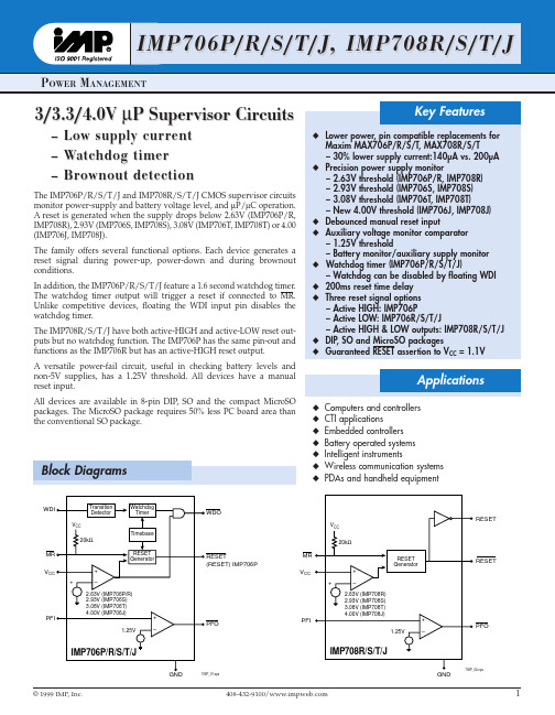
Key Features
x Lower power, pin compatible replacements for Maxim MAX706P/R/S/T, MAX708R/S/T – 30% lower supply current:140µA vs. 200µA
x Precision power supply monitor – 2.63V threshold (IMP706P/R, IMP708R) – 2.93V threshold (IMP706S, IMP708S) – 3.08V threshold (IMP706T, IMP708T) – New 4.00V threshold (IMP706J, IMP708J)
5 GND
706P_03.eps
Ordering Information
Part Number
IMP706PCPA IMP706PCSA IMP706PCUA IMP706PEPA IMP706PESA IMP706RCPA IMP706RCSA IMP706RCUA IMP706REPA IMP706RESA IMP706SCPA IMP706SCSA IMP706SCUA IMP706SEPA IMP706SESA IMP706TCPA IMP706TCSA IMP706TCUA IMP706TEPA IMP706TESA IMP706JCPA IMP706JCSA IMP706JCUA IMP706JEPA IMP706JESA IMP708RCPA IMP708RCSA IMP708RCUA IMP708REPA IMP708RESA IMP708SCPA IMP708SCSA IMP708SCUA IMP708SEPA IMP708SESA IMP708TCPA IMP708TCSA IMP708TCUA IMP708TEPA IMP708TESA IMP708JCPA IMP708JCSA IMP708JCUA IMP708JEPA IMP708JESA
半导体器件芯片常用型号参数12页word文档
半导体器件常用型号参数一、半导体二极管参数符号及其意义CT---势垒电容Cj---结(极间)电容,表示在二极管两端加规定偏压下,锗检波二极管的总电容Cjv---偏压结电容Co---零偏压电容Cjo---零偏压结电容Cjo/Cjn---结电容变化Cs---管壳电容或封装电容Ct---总电容CTV---电压温度系数。
在测试电流下,稳定电压的相对变化与环境温度的绝对变化之比CTC---电容温度系数Cvn---标称电容IF---正向直流电流(正向测试电流)。
锗检波二极管在规定的正向电压VF下,通过极间的电流;硅整流管、硅堆在规定的使用条件下,在正弦半波中允许连续通过的最大工作电流(平均值),硅开关二极管在额定功率下允许通过的最大正向直流电流;测稳压二极管正向电参数时给定的电流IF(AV)---正向平均电流IFM(IM)---正向峰值电流(正向最大电流)。
在额定功率下,允许通过二极管的最大正向脉冲电流。
发光二极管极限电流。
IH---恒定电流、维持电流。
Ii--- 发光二极管起辉电流IFRM---正向重复峰值电流IFSM---正向不重复峰值电流(浪涌电流)Io---整流电流。
在特定线路中规定频率和规定电压条件下所通过的工作电流IF(ov)---正向过载电流IL---光电流或稳流二极管极限电流ID---暗电流IB2---单结晶体管中的基极调制电流IEM---发射极峰值电流IEB10---双基极单结晶体管中发射极与第一基极间反向电流IEB20---双基极单结晶体管中发射极向电流ICM---最大输出平均电流IFMP---正向脉冲电流IP---峰点电流IV---谷点电流IGT---晶闸管控制极触发电流IGD---晶闸管控制极不触发电流IGFM---控制极正向峰值电流IR(AV)---反向平均电流IR(In)---反向直流电流(反向漏电流)。
在测反向特性时,给定的反向电流;硅堆在正弦半波电阻性负载电路中,加反向电压规定值时,所通过的电流;硅开关二极管两端加反向工作电压VR时所通过的电流;稳压二极管在反向电压下,产生的漏电流;整流管在正弦半波最高反向工作电压下的漏电流。
二极管封装大全
军用电子器件目录JUN YONG DIAN ZI QI JIAN MU LU(2005年版)济南半一电子有限公司目录半导体器件选用注意事项 (1)第一部分:二极管 (8)一. 开关二极管 (8)1. 锗金键开关二极管2AK1~20系列 (8)2. 锗金键检波二极管2AP1~31B系列 (9)3. 肖特基检波二极管SP1~31B系列(替代2AP1~31B) (10)4. 肖特基开关二极管SK1~20系列(替代2AK1~20) (11)5. 肖特基开关检波二极管2DKOlO、020、O3O型(替代2AK1~20、2AP1~31B)··126. 硅开关二极管2CK70~86、2CK49~56系列 (13)7. 硅开关二极管1N、1S、1SS、BAV系列 (16)8. 玻璃钝化封装大电流开关二极管RG0.5~5系列 (17)二. 整流二极管 (18)1. 玻封快速硅整流二极管2CZ50~57系列 (18)2. 玻璃钝化整流管1N、RL、6A系列 (19)3. 玻璃钝化高速整流管SF11G~66G系列 (20)4. 贴片玻璃钝化整流管S1~5系列 (21)5. 贴片高速整流管ES1~5系列 (22)6. 肖特基二极管SR0620~510、1N5817~5822系列 (23)7. 肖特基二极管SR735~4060系列 (24)8. 贴片肖特基二极管SS1~36、SS110系列 (25)三. 电压调整(稳压)二极管 (26)1. 硅稳压二极管2CW50~78系列 (26)2. 硅稳压二极管2CW100~121系列 (27)3. 硅稳压二极管ZW50~78系列 (28)4. 硅稳压二极管ZW100~121系列 (29)5. 硅稳压二极管2CW5221~5255(1N5221~5255)系列 (30)6. 硅稳压二极管2CW4728A~4754A(1N4728A~4754A)系列 (31)7. 硅稳压二极管1N746A~759A、1N957A~974A系列 (32)8. 硅稳压二极管1N4352B~4358B系列 (33)9. 硅稳压二极管HZ2~36系列 (34)10. 硅稳压二极管BZX55/C系列 (35)11. 硅稳压二极管BZX85/C系列 (36)四. 电压基准二极管 (37)1. 硅基准稳压二极管2DW14~18系列 (37)2. 硅平面温度补偿二极管2DW230~236系列 (38)五. 电流调整(稳流)二极管 (39)1. 稳流管2DH1~36系列 (39)六. 瞬变电压抑制二极管 (40)1. 单双向瞬变电压抑制二极管TVS500~534系列 (40)2. 单双向瞬变电压抑制二极管TVS1000~1034系列 (41)3. 单双向瞬变电压抑制二极管TVS1500~1534系列 (42)4. 单双向瞬变电压抑制二极管TVS5000~5034系列 (43)第二部分:晶体管 (44)一. 双极型晶体管 (44)1. 硅NPN型平面高频小功率三极管3DG110、3DG111、3DG130系列 (44)2. 硅NPN型外延平面高反压三极管3DG182系列 (45)3. 硅NPN型平面三极管3DK101、3DK106、3DK21系列 (46)4. 硅PNP型外延平面高频小功率三极管3CG111、3CG120、3CG130系列 (47)5. 硅PNP型外延平面高频小功率三极管3CK2、3CK120、3CK130系列 (48)6. 硅PNP型外延平面高频高反压小功率三极管3CG182、3CG184、2N2907系列 (49)7. 硅NPN低频大功率晶体管3DD1~8系列 (50)8. 硅NPN达林顿功率晶体管FH6~8系列 (53)二. 场效应晶体管 (54)1. N沟道MOS型场效应晶体管IRF120~823系列 (54)2. P沟道MOS型场效应晶体管IRF9130~9643系列 (56)3. N沟道结型场效应晶体管3DJ2、3DJ6/66、3DJ7/67/304、3DJ8/68系列 (57)三. 部分替代俄型号晶体管 (59)第三部分:半导体分立器件组件 (60)一. 说明 (60)二. 产品型号 (61)1. 200mA~2A玻璃钝化芯片整流桥DF、1W、RB、W系列 (61)2. 1~4A玻璃钝化芯片整流桥2W、GBP、GBL系列 (62)3. 4~15A玻璃钝化芯片整流桥GBU、GBP系列 (63)4. 15~35A玻璃钝化芯片整流桥GBPC系列 (64)5. 定制式三相整流桥 (65)6. 2Д906A型硅二极管矩阵 (65)7. 双向限幅器SXF0.25~5.8系列 (65)第四部分:电路及模块 (66)一. 集成稳压器 (66)1. 固定输出三端正稳压器CW7800系列 (66)2. 固定输出三端负稳压器CW7900系列 (66)3. 可调输出三端正稳压器CW117系列 (67)4. 可调输出三端负稳压器CW137系列 (67)5. 定制式5V以下电压基准DCW系列 (68)第五部分:外形图 (69)半导体器件选用注意事项半导体器件(以下简称器件)的质量问题,不仅有器件本身所固有的质量和可靠性问题,也有由于用户选择或使用不当造成的器件失效问题。
SC08-13GWA资料
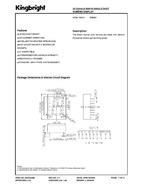
: GRAY FACE, WHITE SEGMENT.
Package Dimensions & Internal Circuit Diagram
Notes: 1. All dimensions are in millimeters (inches), Tolerance is ±0.25(0.01")unless otherwise noted. 2. Specifications are subject to change without notice.
REV : V.1 CHECKED:Joe Lee
DATE: APR/19/2003 DRAWN: L.ZHANG
PAGE: 2 OF 3
元器件交易网
Green
SC08-13GWA
SPEC NO: DSAD2298 APPROVED:J.LU
REV NO: V.1 CHECKED:Joe Lee
Electrical / Optical Characteristics at TA=25°C °
Sy m b o l λpeak λD ∆λ1/2 C VF IR P ar am et er Peak Wavelength Dominate Wavelength Green Green D ev i c e Ty p . 565 568 30 15 2.2 2.5 10 Max . Un its nm nm nm pF V uA Tes t Co n d it io n s I F =20mA I F =20mA I F =20mA VF=0V;f=1MHz I F =20mA V R = 5V
Spectral Line Half-width Green Capacitance Forward Voltage Reverse Current Green Green Green
3164_GFC-8131H GFC-8270H_已仅提供中文类型发号 submariner 短信说
目录页数1. 产品介绍 (1)2. 技术规格 (2)3. 操作前注意事项 (4)3-1. 拆开包装 (4)3-2. 使用电源 (4)3-3. 设备装配及操作 (5)4. 面板介绍 (6)5. 应用 (10)6 维护 (12)6-1. 校准的标准方法 (12)6-2. 清洁………………………………………………………..13计频器GFC-8131H/GFC-8270H 操作手册11.产品介绍计频器的通道A用以测量范围为0.01Hz到120MHz的频率和周期﹐通道B的测量范围为50MHz到1.3(2.7)GHz.为读值之便﹐此产品提供了高分辨率和灵敏度特性﹒GFC-8131H/GFC-8270H 操作手册2 2﹒技术规格 通道A 范围耦合交流直流频率 A 30Hz 到120MHz 0.01Hz 到120MHz 周期 A 8ns 到30ms 8ns 到100s 灵敏度 (rms)50m Vrms 最大到10kHz. 25m Vrms 最大到80MHz 35m Vrms 最大到120MHz(如果频率<10MHz,灵敏度特性只能提供4位稳定显示) 耦合可AC 和DC 切换滤波器通道A 的低通滤波可激活也可关闭 3dB(100kHz)阻抗额定1M Ω与小于40pF 并联 衰减器额定 x1 或 x20 触发电平-2.5V DC 至 +2.5V DC 可调损害电平AC & DC x1DC ~ 2.4kHz 250V(DC+AC rms) 2.4kHz ~ 100kHz 600kV rms Hz/FREQ >100kHz 6V rms AC & DC x 20 DC ~ 20kHz 500V(DC+AC peak) 20kHz ~ 100kHz 10MV rms Hz/FREQ >100kHz 100V rms 通道B 范围50MHz ~1.3GHz (GFC-8131H) 50MHz ~ 2.7GHz (GFC-8270H) 灵敏度GFC-8131H GFC-8270H25mVrms 最大到80MHz 25mVrms 最大到80MHz 15mVrms 最大到700MHz 15mVrms 最大到1GHz 25mVrms 最大到1GHz 25mVrms 最大到2GHz 40mVrms 最大到1.3GHz 50mVrms 最大到2.7GHzGFC-8131H/GFC-8270H 操作手册3耦合AC 阻抗50Ω最大输入电平 3Vrms 正弦波形 通道 A & B 分辨率Gate time 显示位数﹕1s 檔位显示7位﹐100ms 檔位显示6位﹐10ms 檔位显示5位﹒频率测量的最大分辨率分别为100nHz(1Hz 檔位),0.1Hz(100MHz 檔位)﹔对周期测量﹐最大分辨率分别为10nS(1Hz 檔位)﹐0.1fs(100MHz 檔位﹐f=10-15)时基频率---------10MHz老化率(Aging Rate)--------1ppm/month 温度-------5ppm, 23℃±5℃电源-------±0.005ppm(±10% 变动)精度±分辨率 ± 时基误差Gate time 从10ms 到10s 连续可调﹐或输入信号的一个周期﹐取决于较长者﹒显示8位﹐溢出时有 ‘overflow’显示 工作温度 0℃ 40℃ 工作湿度 10 % RH使用电源 100/120/220/230V ±10%,50/60Hz 内部可选﹒最大消耗功率为15VA尺寸大约230(宽) x 95(高) x 280(长) mm 重量大约 2.0kgs 附件操作手册………….x 1电源线…………….x 1测试引线 GTL-101………….x 1GTL-110…………..x 1GFC-8131H/GFC-8270H 操作手册4 3﹒操作前注意事项 3-1. 拆开包装仪器在出厂前已被检测过﹒收到仪器后﹐请打开包装检查是否有运输过程中造成的损坏﹒若有﹐请与运输公司或经销商联系﹒3-2. 使用电源仪器的使用电源可以是以下表格中的任一种﹒请检查后面板上所标示的电源﹐并替换相应的保险丝﹒警告﹒为避免电击﹐请务必将电源线保护接地端子接地﹒当使用电源改变﹐请按以下表格所示替换保险丝﹒ 供应 范围 保险丝 供压 范围保险丝100V 120V 90-110V 108-132VT200mA 250V220V 230V198-242V 207-253VT100mA 250V警告﹒为避免人身伤害﹐换保险丝前请不要连接电源线﹒GFC-8131H/GFC-8270H 操作手册53-3. 设备装配及操作请确保该仪器在适当的环境下使用﹒如果该仪器的使用未遵循规定﹐可能会造成对仪器的损坏﹒GFC-8131H/GFC-8270H 操作手册6 4﹒面板介绍(1). Power ON/OFF电源开/关键﹒(2). Reset 使计频器回初始值零以重新开始计频﹒(3). FREQ A 选择通道A 频率模式 (4). PRID A 选择通道A 周期模式 (5). FREQ B 选择通道B 频率模式 (6). Gate Time(旋钮) 用以连续选择从10ms 到10s 的不同测量时间﹒(最小=输入信号的一个周期)﹒拉出此旋钮﹐显示值可被锁定﹒(7). Gate Time(LED) 当Gate time 发光二极管亮﹐计频器的主闸门电路被开﹐测量在进行﹒(8). TRIG LEVEL拔出此钮﹐触发电平在 –2.5V x ATT 到 (旋钮)+2.5V x ATT 间变动﹒按下此纽﹐进行自动设置功能﹒(9). TRIG LEVEL设置了触发电平﹐该显示灯显示输入(LED)信号高于或低于触发电平﹒GFC-8131H/GFC-8270H 操作手册7(10). LPF/ON 通道A中加入一100kHz 的低通滤波器(11). ATT x1/x20 选择通道A的衰减x1 输入信号直接连到放大器x20 衰减率为20(12). COUP DC/AC 选择通道A的直流或交流耦合﹒(13). INPUT A 通道A的输入BNC(14). INPUT B 通道B的输入BNC(15). S 显示值的单位为秒 (S)(16). Hz 显示值的单位为赫兹(Hz)(17). Exponent (LED) 指示测量值的指数﹐如下﹕ k=1000 M=1,000,000 G=1000,000,000 m=1/1000u=1/1,000,000 n=1/1,000,000,000(18). DISPLAY(LED) 8位红色LED 显示﹒GFC-8131H/GFC-8270H 操作手册8(19). OVFL(LED) OVFL(overflow) 指示灯显示一个或多个最有效数字无法显示﹒GFC-8131H/GFC-8270H 操作手册9前面板图1 前面板GFC-8131H/GFC-8270H 操作手册10 5.应用(1)信号测量若频率范围为0.01Hz~120MHz,按FREQ A 开关﹐将输入信号连到通道A﹒若频率范围为50MHz~1.3(2.7)GHz,按FREQ B 开关﹐将输入信号连到通道B输入BNC.按“PRID” 开关选择通道A 的周期模式﹒(2)闸门时间设置此仪器可连续调整10ms~10s 的闸门时间或一个周期输入﹐取决于时间较长者﹒闸门时间的调整会影响到取样率和读值分辨率﹒逆时针旋转此钮可加快读数﹐顺时针旋转此钮可提高显示分辨率﹒拉出此GATE TIME 钮可锁定当前读值以方便纪录﹒按回此钮则恢复计频器正常操作﹒(3)触发电平调整通过拉出并旋转TRIG LEVEL 钮来调整通道A输入信号的触发电平﹒触发电平可设在 -2.5V x ATT 到 +2.5V x ATT 之间﹒如果按下此纽﹐则被设定在自动触发状态(此钮只适用通道A) (4)LP 滤波器通道A的低频测量噪声会造成读值不稳定﹒LP 滤波器可最小化高频噪声﹐使计频器仅测量需测的低频成分﹒若需要更稳定的读值﹐按下LP FILTER 按键﹐在通道A中内建一个100kHz 的低通滤波器﹒GFC-8131H/GFC-8270H 操作手册11(5)衰减器通道A输入电路中提供一衰减器﹐测量大信号时可提供额外过载保护﹒按下此钮可减小信号20倍﹒当测量信号的幅值未知﹐建议按下此键以提供保护﹒若幅值很低﹐则松开此键以求更高的灵敏度﹒GFC-8131H/GFC-8270H 操作手册12 6.维护以下指示步骤仅可由合格人员执行﹒为避免电击﹐请不要进行操作手册上未指明的操作﹒6-1 校准的标准方法(1)直流位准调整按下TRIG LEVEL 钮并旋到中间位置﹒连接一个10MHz 的正弦波到通道A﹐调整SVR102,降低10MHz 正弦波(标准20mVrms)的幅值到能维持稳定显示﹒(2)标准振荡器调整连接一标准参考频率(10MHz,温度系数<0.2ppm)到通道A﹒调整Gate time 以获得8位数字显示﹒调整SVC201以获得参考频率的最精确显示﹒(3)迟滞偏压调整激活LP FILTER 并设置COUP 到DC 位置﹒按下TRIG LEVEL 钮并旋转到中间位置﹒连接一个1Hz 正弦波30mVrms 到通道A ﹒调整SVR103到最小能维持稳定显示﹒GFC-8131H/GFC-8270H 操作手册136-2.清洁清洁仪器时﹐请用沾有水和温和溶剂的软布﹒不要将清洁剂直接喷到仪器上﹐以防止其渗透到外壳内造成损坏﹒不要用含有汽油﹐苯﹐甲苯﹐二甲苯﹐丙酮等相似的溶剂﹒不要将研磨剂用于仪器的任何部分﹒。
ITU-T G.8131
STUDY GROUP 15
TELECOMMUNICATION STANDARDIZATION SECTOR
STUDY PERIOD 2005-2008
TD 297 Rev1(PLEN/15)
English only Original: English
Document history Issue Notes
1.0
Initial version (date TSB)
ITU-T\COM-T\COM15\C\267E.DOC
-3TD297 Rev1 (PLEN/15)
CONTENTS 1 2 3 4 5 6 7 Scope ............................................................................................................................ 5 References..................................................................................................................... 5 Definitions .................................................................................................................... 5 Symbols and abbreviations ........................................................................................... 7 Conventions .................................................................................................................. 7 Network Objectives ...................................................................................................... 7 Architecture types ........................................................................................................ 8 7.1 T-MPLS trail protection ................................................................................. 8 7.1.1 1+1 trail protection ............................................................................................. 8 7.1.2 1:1 trail protection .............................................................................................. 9 7.2 T-MPLS SNC protection ................................................................................ 9 7.2.1 SNC/S protection ............................................................................................ 9 Switching types............................................................................................................. 9 Operation types ............................................................................................................. 9 9.1 Non-revertive operation.................................................................................. 9 9.2 Revertive operation ........................................................................................ 10 Automatic Protection Switching (APS) protocol ......................................................... 10 10.1 APS payload structure .................................................................................... 10 10.2 APS protocol type........................................................................................... 11 Application architectures .............................................................................................. 12 11.1 Unidirectional 1+1 trail protection switching................................................. 12 11.2 Bidirectional 1:1 trail protection switching .................................................... 13 11.3 11.4 12 Unidirectional 1+1 SNC/S protection switching .......................................... 14 Bidirectional 1:1 SNC/S protection switching ............................................... 14
CST微波工作室--用户全书

目录I 目录卷一基础入门第一章概述 (3)欢迎 (3)如何快速起步? (3)CST微波工作室®的功用为何? (3)谁应使用CST微波工作室®? (4)CST微波工作室®的主要特点 (5)概要 (5)结构建模 (5)瞬态求解器 (6)频域求解器 (7)本征模求解器 (8)模式分析求解器 (8)结果显示及导出结果的计算 (8)导出结果 (9)自动操作 (9)关于本卷 (9)版式约定 (9)您的反馈 (10)联系CST China (10)CST China (10)CST总部 (10)技术支持 (11)第二章安装 (12)安装需求 (12)IICST微波工作室®用户全书(卷一/卷二)软件需求 (12)硬件需求 (12)License选项 (12)安装指南 (13)提供密码文件 (14)第三章快速演练 (15)启动软件 (15)用户界面概览 (16)创建并观察一些简单结构 (17)创建第一个“方块” (17)常用基本图形概述 (19)选择预先定义的图形、用组件来将图形分组和指定材料特性 (20)改变视角 (23)几何变换 (25)使用布尔操作来合并图形 (28)选取模型的点、边、面 (30)倒直角和倒圆角 (31)拉伸、旋转和渐变 (32)局部坐标系 (38)历史记录 (41)历史树 (43)创建曲线 (45)局部修改 (48)创建平面导线 (50)第一个应用实例 (52)结构 (52)启动CST微波工作室® (53)打开仿真向导 (53)定义单位 (54)定义背景材料 (55)结构建模 (55)定义端口 (62)定义频率范围 (64)目录III定义边界条件和对称面 (64)查看网格 (67)开始仿真 (68)分析端口模式 (70)分析S参量 (71)自适应网格加密 (73)分析各频率的电磁场 (77)参量化模型和自动优化结构 (80)总结 (95)应该选用哪个求解器? (95)天线计算 (98)数字信号激励 (101)频域计算 (104)本征模(谐振器)计算 (106)模式分析计算 (109)离散端口 (110)提取SPICE网络模型 (111)基于模型降阶法的网络参量提取 (112)基于传输线的网络参量提取 (115)第四章寻求更多信息 (119)仿真向导 (119)教程 (120)实例 (121)在线帮助 (121)参见《CST微波工作室®用户全书》(卷三:高级概念) (121)寻求技术支持 (122)宏语言文档 (122)版本更新记录 (122)附录快捷键一览表 (123)IVCST微波工作室®用户全书(卷一/卷二)主结构视图中的通用快捷键 (123)编辑栏可用快捷键 (126)卷二应用算例第一章魔T (129)几何建模及求解器设置 (130)概述及模型尺寸 (130)几何建模 (131)结果 (140)1D结果(端口信号,S参量) (140)2D和3D结果(端口模式及场监视器) (141)精度分析 (143)获取更多信息 (146)第二章同轴连接器 (147)几何建模及求解器设置 (148)概述及模型尺寸 (148)几何建模 (148)设置求解器并计算S参量 (167)结果 (173)1D结果(端口信号,S参量) (173)2D和3D结果(端口模式及场监视器) (174)精度分析 (176)获取更多信息 (179)第三章微带相桥 (180)几何建模及求解器设置 (181)概述及模型尺寸 (181)目录V 几何建模 (182)结果 (200)1D结果(端口信号,S参量) (200)2D和3D结果(端口模式及场监视器) (202)精度分析 (203)获取更多信息 (206)第四章贴片天线 (208)几何建模及求解器设置 (209)概述及模型尺寸 (209)几何建模 (209)结果 (223)1D结果(端口信号,S参量) (224)2D和3D结果(端口模式及远场监视器) (225)计算天线阵 (227)精度分析 (230)贴片天线阵 (232)几何建模步骤 (232)合并结果 (235)并行激励 (238)获取更多信息 (241)第五章腔体 (242)几何建模及求解器设置 (243)概述及模型尺寸 (243)几何建模 (244)求解器设置 (250)使用AKS的本征模计算 (252)查看本征模式及计算Q值 (256)精度分析 (258)VICST微波工作室®用户全书(卷一/卷二)使用JD(无耗)的本征模计算 (263)获取更多信息 (266)第六章窄带滤波器 (267)几何建模及求解器设置 (268)概述及模型尺寸 (268)几何建模 (269)设置求解器并计算S参量 (282)结果 (291)1D 结果(S参量) (291)2D和3D结果(端口模式和三维模式) (291)精度分析 (293)其他可选的求解器 (298)JD(无耗)本征模求解器 (298)频域求解器 (301)获取更多信息 (303)。
CSTM电站用马氏体耐热钢08Cr9W3Co3VNbCuBN(G115)对焊管件编制说明

《电站用马氏体耐热钢08Cr9W3Co3VNbCuBN(Gl 15)对焊管件》团体标准编制说明起草编制组2020年6月《电站用马氏体耐热钢08Cr9W3Co3VNbCuBN(G115)对焊管件》团体标准编制说明一、工作简况1.任务来源2017年12月20日,全国锅炉压力容器标准化技术委员会于对08Cr9W3Co3VNbCuBN (GII 5®)钢管进行了市场准入技术评审,评审意见认为,GH 5® 钢管系列温度(IOO-700 ℃)高温力学性能实验结果符合金属材料高温力学性能规律,进行了大量的持久实验,其中最长点为38803 h,累计台时超过5.0xl()5h, 650 C高温抗氧化性能能够达到GB/T 13303《高温抗氧化性能测试方法》规定的1级(完全抗氧化性)要求,按相关标准生产的Gu5®钢管能满足GB/T 16507 标准的要求,可以用于超(超)临界锅炉的集箱、蒸汽管道、受热面管子等部件,以及类似工况的受压元件,集箱及管道的钢管允许最高壁温650 ℃;受热面管子允许最高壁温660 C,必要时可采用适当的抗氧化措施。
2018年,国家能源局正式批复大唐郛城630℃超超临界二次再热国家电力示范项目。
GII5®钢是目前世界范围唯一可工程上应用于630-650℃蒸汽温度的新型马氏体耐热钢,是大唐郛城630C超超临界二次再热国家电力示范项目锅炉集箱和主蒸汽管道等最高温度段唯一可选材料。
2017年12月29日,CSTM标准技术委员会发布《电站用马氏体耐热钢08Cr9W3Co3VNbCuBN(G115)无缝钢管》团体标准,标准号:T/CSTM 00017-2017o在大唐郛城630C超超临界二次再热示范项目设计和建设中,最高温度段管道选用G115钢,关键位置布置的管道与管道连接处需用G115钢管件。
因此,有必要建立电站用马氏体耐热钢08Cr9W3Co3VNbCuBN(GΠ5)对焊管件标准,填补标准空白。
