91C1DD24D10R51中文资料
EtherNet IP直接输入型步进电机控制器(伺服24VDC)系列JXC91 安装与维护手册说明书

Installation & Maintenance Manual EtherNet/IP Direct input typeStep Motor Controller (Servo 24VDC)Series JXC91This manual contains essential information for the protection of users and others from possible injury and/or equipment damage.•Read this manual before using the product, to ensure correct handling,and read the manuals of related apparatus before use.•Keep this manual in a safe place for future reference.•These instructions indicate the level of potential hazard by label of "Caution", "Warning" or "Danger", followed by important safety information which must be carefully followed.•To ensure safety of personnel and equipment the safety instructions in this manual and the product catalogue must be observed, along with other relevant safety practices.WarningWarningThe compatibility of the product is the responsibility of the person who designs the equipment or decides its specifications.Since the product specified here is used under various operatingconditions, its compatibility with specific equipment must be decided by the person who designs the equipment or decides its specifications based on necessary analysis and test results.The expected performance and safety assurance of the equipment will be the responsibility of the person who has determined its compatibility with the product.This person should also continuously review all specifications of the product referring to its latest catalog information, with a view to giving due consideration to any possibility of equipment failure when configuring the equipment.Only personnel with appropriate training should operate machinery and equipment.The product may become unsafe if handled incorrectly.The assembly, operation and maintenance of machines or equipment must be performed by an operator who is appropriately trained and experienced.Do not attempt to service or replace product and machinery/equipment until safety is confirmed.1. The inspection and maintenance of machinery/equipment should only be performed after measures to prevent falling or runaway of the driven objects have been confirmed.2. When the product is to be removed, confirm that the above safety measures are implemented and the power from any appropriate source is cut, and read and understand the specific product precautions of all relevant products carefully.3. Before machinery/equipment is restarted, take measures to prevent unexpected operation and malfunction.CautionThe product is provided for use in manufacturing industries.The product herein described is basically provided for peaceful use in manufacturing industries.If considering using the product in other industries, consult SMC beforehand and provide specifications or a contract, if necessary.If anything is unclear, contact your nearest sales branch.Refer to the operation manual on the SMC website (URL ).Contact SMC beforehand and take special consideration of safety measures if the product is to be used in any of the following conditions:1. Conditions and environments outside of the given specifications, or use outdoors or in a place exposed to direct sunlight.2. Installation on equipment in conjunction with atomic energy, railways,air navigation, space, shipping, vehicles, military, medical treatment,combustion and recreation, or equipment in contact with food and beverages, emergency stop circuits, clutch and brake circuits in press applications, safety equipment or other applications unsuitable for the standard specifications described in the product catalog.3. An application which could have negative effects on people, property, or animals requiring special safety analysis.4. Use in an interlock circuit, which requires the provision of doubleinterlock for possible failure by using a mechanical protective function,and periodical checks to confirm proper operation.WarningThe Communication cable must be connected to a PC using a USB cable through a conversion unit.Do not connect the teaching box to a PC.Do not use LAN cable to connect to the controller, as this may cause damage to the personal computer.2 Product configurationTo P1, P2∗1∗1●ControllerOptionsPLCTo SIPCorEtherNet/IP Controller power supply 24VDC•Power supply plug (Included)<Applicable wire size>AWG20 (0.5mm )•Communication cable •Conversion unit•Controller set up kit (Controller settingsoftware, communication cable, conversion unit,USB cable are included)Part No: LEC-W2•Teaching box(3m cable is provided.)Product number:LEC-T1-3□G□•USB cable (A-mini B type)∗1 These items are included when ordered using the part number for an actuator set.∗2 The latest version of the controller setting software must be used.Upgrade software can be downloaded from SMC website./Electric actuatorTo ENCTo MOT To PWRLED displayRefer to the table below for the details of the LED status.∗2CautionDo not turn OFF the input power supply for the controller or disconnect and connect the cable while the data is being written to EEPROM (PWR LED (green) is flashing).∗Possibility of incorrect/corrupted data (step data, parameter)•Actuator cable(Robotic type cable)Model number:•LE-CP-□-□(Robotic type cable)•LE-CP-□-□-S (Standard cable)•Conversion cable Product no.:P5062-5(2) GroundingPlace the grounding cable with crimped terminal between the M4 screw and shakeproof washer as shown below and tighten the screw.Refer to the operation manual on SMC website (URL ).CautionThe M4 screw, cable with crimped terminal and shakeproof washer must be prepared by the user.The controller must be connected to Ground to reduce noise.URL (Global) (Europe)Specifications are subject to change without prior notice from the manufacturer.© 2016 SMC Corporation All Rights Reserved13 ContactsAUSTRIA (43) 2262 62280-0NETHERLANDS (31) 20 531 8888 BELGIUM (32) 3 355 1464 NORWAY (47) 67 12 90 20 CZECH REP.(420) 541 424 611 POLAND (48) 22 211 9600 DENMARK (45) 7025 2900 PORTUGAL (351) 21 471 1880FINLAND (358) 207 513513 SLOVAKIA (421) 2 444 56725 FRANCE (33) 1 6476 1000 SLOVENIA (386) 73 885 412GERMANY (49) 6103 4020 SPAIN (34) 945 184 100 GREECE (30) 210 271 7265 SWEDEN(46) 8 603 1200 HUNGARY (36) 23 511 390 SWITZERLAND (41) 52 396 3131 IRELAND (353) 1 403 9000 UNITED KINGDOM(44) 1908 563888ITALY(39) 02 92711BULGARIA (359) 2 974 4492ESTONIA (372) 651 0370 ROMANIA (40) 21 320 5111LATVIA (371) 781 77 00 LITHUANIA(370) 5 264 8126 12 TroubleshootingRefer to the operation manual on the SMC website (URL ).(1) MountingThe controller can be direct mounted using screws or mounted on a DIN rail.Details of the controller mounting options are shown below.Mounting directionBasic specifications[1] Direct mounting (JXC917-□)(Mounting with two M4 screws)Mounting directionGround wire[2] DIN rail mounting (JXC918-□)(Mounting with DIN rail)Hook the controller on the DIN rail andpress lever A in the direction of the arrow to lock it.Ground wireBefore locked onto DIN railLocked onto DIN railGround wireDIN railACable with crimping terminal M4 screwShakeproof washerControllerPower supply plug specificationsThe specifications of the power supply plug supplied with the controller are shown below.Power supply plugIP address×Manual setting of IP address8 Initial Setting methodSetting of switch (IP address)Turn OFF the power supply while setting the switch.The rotary switch should be set with a small flat blade screwdriver.Refer to the operation manual on the SMC website (URL ).。
DediProg 1.0 专用编程器指南说明书
Table of ContentsI.Introduction (3)II.Conditions and Limitations (3)III.How to start (3)mand List (4)V.Revision History (6)Important notice:This document is provided as a guideline and must not be disclosed without consent of DediProg. However, no responsibility is assumed for errors that might appear.DediProg reserves the right to make any changes to the product and/or the specification at any time without notice. No part of this document may be copied or reproduced in any form or by any means without prior written consent of DediProg.--device arg (Work with all Basic Switches)- 1: Activate only the programmer connected to USB1- n: Activate only the programmer connected to USBnNote: If '--device' is not used, the command will be executed on allconnected programmer.--fix-device arg Fix programmer serial number with programmer sequence.- Instructions must be enclosed in double quotation marks("")Example:dwcmd --fix-device "1 SPU000001"--list-device-id arg - 0 : List all programmers’ ID from USB1 to USBn (Default)Note: The sequence is assigned by OS during USB plug-in.- 1: Prompt the device ID of programmer connected to USB1.- n: Prompt the device ID of programmer connected to USBn. Miscellaneous options:-t [ --timeout ] arg (=600) Timeout value in seconds-i [ --silent ] Suppress the display of real-time timer counting- Used when integrating with 3rd-party tools(e.g. IDE)--log arg Write operation result into a file(Default is located underC:\DediLog\dwcmd-xxxxx.log)Example:dwcmd --usb-prj d:\test.dprj --log d:\result.txtNote:Windows Command Line does not support ProgMaster series.Usage Examples:1. dwcmd -d file.dprj -rDownload project file to StarProg and run it.2. dwcmd -rRun project from the StarProg embedded SD card.3. dwcmd --usb-prj file.dprjExecute project file via USB.4. dwcmd --usb-prj file.dprj --device 1Execute Programmer 1 project file.5. dwcmd -d file.dprj --device 1Download project file to programmer 16. dwcmd -r --device 1Execute project file7. dwcmd -d file.dprj -r --device 2Download project file to StarProg and run the project file on programmer 2.8. dwcmd -d file.dprj -r --log d:\result.txtDownload project file to StarProg and save the operation result to d:\result.txt.V.Revision HistoryDate Version Changes05/11/2016 1.0 Initial releaseDediProg Technology Co., Ltd- Taiwan Headquarter TEL: 886-2-2790-7932FAX: 886-2-2790-79164F., No.7, Ln. 143, Xinming Rd., Neihu Dist., Taipei City 114, Taiwan- Shanghai Office TEL: 86-21-5160-0157 FAX: 86-21-6126-3530Room 503, Block E, No.1618, Yishan Road, Shanghai, ChinaTechnical Support:support@Sales Support:sales@Information furnished is believed to be accurate and reliable. However, DediProg assumes no responsibility for the consequences of use of such information or for any infringement of patents or other rights of third parties which may result from its use. Specifications mentioned in this publication are subject to change without notice.This publication supersedes and replaces all information previously supplied.All rights reservedPrinted in Taiwan.。
91MCE系列限位开关说明书

DESCRIPTIONThe 91MCE Series limit switch is a compliment to Honeywell’s existing product line of smaller, lower cost limit switches. Designed for modern industrial OEMs, the miniature package size fits in applications where space is limited. The small package size can be gangmounted for applications requiring more than two switch circuits. The 20 mm mounting pattern meets most globally accepted mounting standards.This product family offers the user many options including a variety of different actuator styles. Connection options include pre-leaded cable in various lengths or M12 connectors, both with side or bottom exits. Design flexibility is further enhanced with the availability of both slow action and snap action circuitry. Direct acting contacts are designed to open the NC contact when actuated. The epoxy-sealed rugged die-cast housing provides enhanced environmental durability.Priced competitively, the 91MCE is a drop-in replacement to many products, and provides enhanced quality that customers expect from Honeywell.FEATURES•• Sealed to IP67; NEMA 1, 4, 12, 13 suitable for outdoor applications• CE, UKCA, cULus, CCC approvals meet most global approvals• Nine actuator styles offer design flexibility• Slow-action and snap-action circuitry options• Pre-leaded cable and M12 connector options• Expected mechanical life: 5 million operations• Side exit (standard) and bottom exit connection options91MCESERIESMICRO SWITCH Miniature Compact Limit Switches002311Issue 3POTENTIAL APPLICATIONS• Machine equipment • Material handling • Aerial lifts • Forklifts• Off road and outdoor equipmentPORTFOLIOThe 91MCE Series is part of the 14CE, 914CE, NGC, SZL-VL-S, SSCE and SL1 Series of miniature limit switches.Switches.PRODUCT NOMENCLATURE91MCESwitch Type16Actuator TypeCable/Connector Exit91MCE Series Miniature Compact Limit Switch1Cable Length*ConnectorNOTE: not all combinations of model codes are available.Please contact your Honeywell provider/representative for assistance.PSwitch TypeBLever TypeFOR MORE INFORMATION Honeywell Advanced Sensing Technologies services its customers through a worldwide network of sales offices and distributors. For application assistance, current specifications, pricing or the nearest Authorized Distributor, visit our website or call:USA/Canada +1 302 613 4491Latin America +1 305 805 8188 Europe +44 1344 238258 Japan +81 (0) 3-6730-7152 Singapore +65 6355 2828 Greater China +86 4006396841HoneywellAdvanced Sensing Technologies830 East Arapaho RoadRichardson, TX 75081 WARRANTY/REMEDYHoneywell warrants goods of its manufactureas being free of defective materials andfaulty workmanship during the applicablewarranty period. Honeywell’s standard productwarranty applies unless agreed to otherwise byHoneywell in writing; please refer to your orderacknowledgment or consult your local salesoffice for specific warranty details. If warrantedgoods are returned to Honeywell during theperiod of coverage, Honeywell will repair orreplace, at its option, without charge thoseitems that Honeywell, in its sole discretion,finds defective. The foregoing is buyer’s soleremedy and is in lieu of all other warranties,expressed or implied, including those ofmerchantability and fitness for a particularpurpose. In no event shall Honeywell beliable for consequential, special, or indirectdamages.While Honeywell may provide applicationassistance personally, through our literatureand the Honeywell web site, it is buyer’s soleresponsibility to determine the suitability ofthe product in the application.Specifications may change without notice.The information we supply is believed tobe accurate and reliable as of this writing.However, Honeywell assumes no responsibilityfor its use.m WARNINGMISUSE OFDOCUMENTATION• The information presented in thisproduct sheet is for reference only.Do not use this document as aproduct installation guide.• Complete installation, operation,and maintenance informationis provided in the instructionssupplied with each product.Failure to comply with theseinstructions could result in death orserious injury.002311-3-EN | 3 | 12/21。
LOREX SG15OD2844161 网络查看器软件使用说明书

Copyright © 2006 LOREX Technology Inc. Instruction ManualEnglish Version 1.0MODEL:SG15OD2844161Table of ContentsTable of ContentsAbout Netviewer (2)System Requirements (3)Software Installation (4)Configuring the Online DIPS Server Account (7)Router Port Forwarding (11)NetViewer Software (12)Menu Functionality (12)Main Screen Functionality (16)Disconnecting from the DVR (18)Hard Drive Viewer Software (19)Save Image to File (22)Record to Local Hard Drive (22)About NetviewerThe NetViewer software package allows you to access your DVR from a remote location to view live and previously recorded video.• View and Record from your PC - Connect your Observation System to your Network• Minimum System Requirements: Windows XP, Pentium 4 processor with 256MB RAM2System Requirements System RequirementsThe NetViewer software (included with the System) has the following installation requirements.Minimum System Requirements:Operating System Windows 2000Windows XP Home EditionWindows XP ProfessionalProcessor Pentium 4 - 1.5 GHz Processor (or equivalent)Memory256 MB RAMHard Drive50 MB - Installation space required* Additional Hard Drive space required for recording.Recorded file size will vary depending on recordingquality settingsRecommended System Requirements:Operating System Windows XP Home EditionWindows XP ProfessionalProcessor Pentium 4 - 3 GHz Processor (or equivalent)Memory1024 MB RAMHard Drive50 MB - Installation space required* Additional Hard Drive space required for recording.Recorded file size will vary depending on recordingquality settings34Software InstallationSoftware InstallationPlace the NetViewer Installation CD in the CD-ROM Drive of your Computer. The Software Install Wizard for the 4Channel DVR Utility will begin.1. Click NEXTto continue the InstallationNOTE : If the Installation Process does not automatically start, you will have to begin the installation process manually:• Double Click the MY COMPUTER icon on your Desktop• Double Click the CD-ROM DRIVE (Drive Letter will vary depending on the number of drives in your computer)• Double Click the SETUP.EXE file (may appear as SETUP with no file extension, depending on your system settings.The Installation Process will begin.Software Installation2. The Destination Folder dialogue window allows you to select the Installation Directory. Click theCHANGE button to change the Installation Directory, or click NEXT to accept the default location:• C:\Program Files\Lorex\4Channel DVR Utility\ Arraybutton to begin the Installation.3. Click the INSTALL5Software Installation4. Click on the FINISHbutton to complete the Installation Process.NOTE: The following Program Shortcuts will be created:• Start Menu - Programs - Lorex - 4Channel DVR Utilityz AviGenz Install MS-MPEG4 Codecz NetViewerz HDDViewerz Manualsz Uninstall 4Channel DVR Utility• Desktop Shortcuts for:z NetViewer zHDDViewer67Configuring the Online DIPS Server AccountConfiguring the Online DIPS Server AccountTo remotely access the DVR, you will need the following information from the DVR Combo Unit. Press the ONE FRAME button on the MAIN CONTROL or on the REMOTE CONTROL while in Camera viewing mode to locate the following System Information:• Version: _________________________________________________________• IP ADDRESS: ____________ . ____________ . ____________ . ____________• MAC ADDRESS: _______ : _______ : _______ : _______ : _______ : _______• PRODUCT ID: _________________________ - _________________________This information can also be located from the System MENU - NETWORK settings. Refer to the DVR COMBO MANUAL for further information on MENU settings.Once the above information has been recorded, the ONLINE DIPS SERVER can be configured.1. Open a Web Browser and navigate to /Configuring the Online DIPS Server Account2. Click on SIGNIN on the Navigation Bar to create a new account. Enter information for:• Login ID• Name• PasswordClick the SIGNIN button to create your account.A confirmation dialogue box will appear indicating a successful account setup:8Configuring the Online DIPS Server Account3. Click on the LOGIN button to log into the DIPS ONLINE SERVER using your newly createdaccount information:• Login ID• PasswordClick the LOGIN button to Sign In.A confirmation box will appear indicating a successful Login:The Navigation bar options will change once you have successfully logged into the system:910Configuring the Online DIPS Server Account4. Click on REGISTER DIP on the Navigation Bar to add your DVR information. Enter information for:• MAC ADDRESS - Information found on the DVR Combo Unit.• PRODUCT ID - Information found on the DVR Combo Unit.• DESCRIPTION - Any name you would like to call the unit (i.e. Warehouse, House, NY Office)Click the REGISTER DIP button to add this information to your account.A confirmation box will appear indicating that the information has been entered successfully:5. To view the DIP Settings, click the LIST DIPon the Navigation Bar.Router Port ForwardingComputerInternal IP192.168.0.2DVRInternal IP192.168.0.3RouterInternal IP192.168.0.1RouterExternal IP216.13.154.34NETWORK EXAMPLEInternet Internal NetworkRouter Port ForwardingYou will need to enable port forwarding on your Router to allow for external communications with your System. The following ports will need to be forwarded:• 14337• 14338Computers, DVR’s, and other devices inside your network can only communicate directly with each other within the internal network. Computers and systems outside your network cannot directly communicate with these devices. When a system on the internal network needs to send or receive information from a system outside the network (i.e. from the Internet), the information is sent to the Router.When a computer on the Internet needs to send data to your internal network, it sends this data to the external IP address of the Router. The Router then needs to decide where this data is to be sent to. This is where setting up Port Forwarding becomes important.Port Forwarding tells the router which device on the internal network to send the data to. When you set up port forwarding on your Router, it takes the data from the external IP address:port number and sends that data to an internal IP address:port number (i.e Router External IP 216.13.154.34:14337 to DVR Internal IP 192.168.0.3:14337).The instructions found online in the Router Configuration Guide will assist you in the port forwarding configurations for a selection of different router models.Visit our Consumer Guides Support website at for more details.NetViewer SoftwareNetViewer SoftwareMenu FunctionalityThe Connect Menu options allow you to use your PC to remotely connect to your DVR (once you have successfully configured your system on the ONLINE DIPS SERVER and set the PORT FORWARDING on your specific model of Router)1. DDNS Connect - Connect to the DVR using the USER ID and PASSWORD that was used to configure the ONLINE DIPS SERVER account.Click the checkbox beside USER NAME SAVEto keep your USER ID in the program memory.Click the CONNECT button to access the DVR.2. IP CONNECT - Connect to the DVR using the IP ADDRESS and PASSWORD found in the DVR’s’ NETWORK SETTINGS .Click the checkbox beside SAVE IP ADDRESSto keep your IP ADDRESS in the programmemory.Click the CONNECTbutton to access the DVR.1.2.3.4.5.6.7.8.NetViewer Software 3. MAC CONNECT - Connect to the DVR using theMAC ADDRESS and PASSWORD found in theDVR’s’ NETWORK SETTINGS.Click the CONNECT button to access the DVR.4. DDNS CONFIGURATION - Connection Addressfor the DIPS ONLINE SERVER. The defaultaddress is• This Address should not be changed.NOTE: Once a successful connection has been made to the ONLINE DIPS SERVER, a listing of all configured devices will appear.Select the Device from the DVR LIST, and click the CONNECT button to start REMOTE VIEWING.NetViewer Software5. DISCONNECT - Disconnects the application from the DVR.6. EXIT - Exits the program.7. STATISTICS - Displays the Network Statistics for the connected DVR Unit.NetViewer Software 8. DVR Management - Displays the Control Settings for the DVR Unit:• HARD DISK INFORMATION - Displays theInstalled DVR Hard Drive information. Clicking onthe HDD INFORMATION button will display adialogue box with detailed Hard Drive information.• VIDEO QUALITY - Set the Video Display Quality.Options include Low, Med, High and Best.• RECORD FRAME RATE - Set the number ofFrames Per Second to Record between 1-30 fps.• ALARM ON DURATION - The duration that a Camerawill stay in Alarm. Set between 1-10 seconds.• SENSOR RECORD DURATION - The duration that a Sensor will record• AUDIO RECORDING - Sets Audio Recording to ENABLE/DISABLE.• DVR SPEAKER - Sets the DVR Speaker to ENABLE/DISABLE.• INPUT CHANNELS / RECORD CHANNELS - ENABLE/DISABLE the INPUT and RECORD for channels CH1-CH4 by setting them individually ON/OFF.• DVR TIME - Set the time on the DVR UNIT. Settings are for Year, Month, Day, Hour, Minute and Second.Once the settings have been changed, click the UPDATE SETTING button to update the DVR UNIT. Click the CLOSE WINDOW button to exit the dialogue box.NetViewer SoftwareMain Screen FunctionalityThe Main Screen Functionality options allow you to remotely control your DVR Combo unit.1. CH1 - CH4 - Currently displayed Camera2. DATE / TIME - The Date and Time on the DVR Combo Unit3. CONNECTION DETAILS :• Connected - Indicates Connection status as CONNECTED or DISCONNECTED• NTSC IP - Indicates the IP address of the DVR• Speed - Indicates the current data receiving (in Mb / sec.)• Frame Rate - The currently displayed Frame Rate of the Camera (in fps)1.2.3.4.5.6.7.NetViewer Software4. CHANNEL CONTROL - Control panel for Channel Control. Allows the user to switch between CH1 - CH4 by pressing the corresponding Channel Button.5. REMOTE DVR CONTROL - Allows the user to remotely control the DVR Unit:• REC BUTTON - Start recording on the DVR Unit.• STOP - Stops recording or playback on the DVR Unit.• REWIND - Rewinds the playback of a previously recorded event.• FAST FORWARD - Fast Forwards the playback of a previously recorded event.• PLAY - Displays a listing of previously recorded events on the DVR Unit:6. LOCAL CONTROL - Controls the playback and recording to the LOCAL PC . Controls work in the same way as the REMOTE DVR CONTROLS , however all PLAYBACK and RECORDING are taking place from the Local PC Hard Drive(s).7. VOLUME- Controls the Volume on the currently displayed Video Image.Time Search - Select the DVRMaster Hard Drive and set theSTART and END TimesTime Search Playback - OnceTimes have been selected, click toPlay previously recorded events fromthe DVR.Event Playback - Displays a listing ofPreviously Recorded Events on theDVR..Start Event Playback - Once anEvent has been selected, click to Playpreviously recorded events from theDVR.NetViewer SoftwareDisconnecting from the DVRThe connection to the DVR can be closed in two ways.1. Disconnecting from the NetViewer Application - To close the Connection to the connected DVRunit:• Click on CONNECT from the MAIN MENU to access the Drop Down Menu.• Click on DISCONNECT to stop remote viewing of the DVR Unit.2. Disconnecting from the DVR Combo Unit - If a user presses any buttons on either the DVRFRONT PANEL BUTTONS or DVR REMOTE CONTROL, the NetViewer application connection to the unit will be terminated. The following message will appear on screen:If the connection to the DVR is terminated, a new connection will need to be made using the options on the CONNECT menu.Hard Drive Viewer Software Hard Drive Viewer SoftwareThe Hard Drive Viewer Software allows you to view the contents of your DVR Hard Drive when the drive is removed from the DVR and physically connected to a PC.NOTE: It is not recommended that you remove the Hard Drive from theSG15OD2844161DVR Combo Unit. Consult a technical support represenative before attempting to remove the drive from the unit.The Data on the DVR Hard Drive cannot be viewed by a PC without using the Hard Drive Viewer Software.Menu Functionality1.2.5. 6.7.8.9.4.3.Hard Drive Viewer Software1. HARD DRIVE CONNECTION - Once the Hard Drivefrom the DVR Unit is connected to the PC, click the Hard Drive Connection button. A secondary dialogue box will appear once the drive is found - click on the CONNECT BACKUP HDD button to connect.2. CONNECTION STATUS INDICATOR - Indicates theconnection status of the Hard Drive as either CONNECTED or NOT CONNECTED.3. HARD DRIVE INFORMATION - Displays theinformation about the currently connected Hard Drive in a dialogue window:• Drive Capacity• Total Space• Used Space• Free Space4. EVENT TIME SEARCH - Displays a list of previouslyrecorded events on the Hard Drive.Click on one of the listed events and click the OKbutton to playback the recorded event.5. EVENT SEARCH - Search through previously recordedevents by• Year / Month / Day• Hour / Minute / SecondClick the SEARCH button to retrieve a listing of events.21Hard Drive Viewer Software6. PLAYBACK CONTROLS - Control the playback of recorded video• REC BUTTON - Copies the current recording to the PC Hard Drive as an AVI file.• STOP - Stops playback.• REWIND - Rewinds the playback.• FAST FORWARD - Fast Forwards the playback.• PLAY - Playback of the selected event:7. VOLUME CONTROL - Controls the Volume of the recorded playback.8. DISPLAY SCREEN - Display area for the video playback.9. SLIDING PLAYBACK BAR - Adjust the current playbackZOOM Channel ControlWhen playback is occurring in QUAD mode, an individual channel can be enlarged to full screen mode. Left Click (with the PC Mouse) on any of the desired Channels to ZOOM in - the channel will be displayed on screen in FULL SCREENmode.Hard Drive Viewer Software 22Hard Drive Viewer Software23It’s all on the webProduct InformationUser Manuals Quick Start Guides Specification Sheets Software Upgrades Firmware Upgrades LOREX Technology Inc.VISIT。
Vigor2920 系

Vigor2920 系列雙WAN安全防護路由器快速安裝手冊版本: 1.0韌體版本: V3.3.3.1日期: 19/07/2010因手冊更新無法及時通知用戶,請隨時連上居易網站,取得最新的手冊內容。
版權資訊版權聲明© 2010版權所有,翻印必究。
此出版物所包含資訊受版權保護。
未經版權所有人書面許可,不得對其進行拷貝、傳播、轉錄、摘錄、儲存到檢索系統或轉譯成其他語言。
交貨以及其他詳細資料的範圍若有變化,恕不預先通知。
商標本手冊內容使用以下商標:z Microsoft為微軟公司註冊商標z Windows視窗系列,包括Windows 95, 98, Me, NT, 2000, XP 以及其Explorer均屬微軟公司商標z Apple以及Mac OS均屬蘋果電腦公司的註冊商標z其他產品則為各自生產廠商之註冊商標安全說明和保障安全說明z在設置前請先閱讀安裝說明。
z由於路由器是複雜的電子產品,請勿自行拆除或是維修本產品。
z請勿自行打開或修復路由器。
z請勿把路由器置於潮濕的環境中,例如浴室。
z請將本產品放置在足以遮風避雨之處,適合溫度在攝氏5度到40度之間。
z請勿將本產品暴露在陽光或是其他熱源下,否則外殼以及零件可能遭到破壞。
z請勿將LAN網線置於戶外,以防電擊危險。
z請將本產品放置在小孩無法觸及之處。
z若您想棄置本產品時,請遵守當地的保護環境的法律法規。
保固自使用者購買日起二年內為保固期限,請將您的購買收據保存二年,因為它可以證明您的購買日期。
當本產品發生故障乃導因於製作及(或)零件上的錯誤,只要使用者在保固期間內出示購買證明,居易科技將採取可使產品恢復正常之修理或更換有瑕疵的產品(或零件),且不收取任何費用。
居易科技可自行決定使用全新的或是同等價值且功能相當的再製產品。
下列狀況不在本產品的保固範圍內:(1)若產品遭修改、錯誤(不當)使用、不可抗力之外力損害,或不正常的使用,而發生的故障;(2) 隨附軟體或是其他供應商提供的授權軟體;(3) 未嚴重影響產品堪用性的瑕疵。
国产ds1991L-F5 参数说明书

SELOCKEY.SOA§ 1,152-bit secure read/write, nonvolatilememory§ Secure memory cannot be decipheredwithout matching 64-bit password§ Memory is partitioned into 3 blocks of 384bits each§ 64-bit password and ID fields for eachmemory block§ 512-bit scratchpad ensures data transferintegrity§ Operating temperature range: -40°C to+70°C§ Over 10 years of data retentionCOMMON Button FEATURES§ Unique, factory-lasered and tested 64-bitregistration number (8-bit family code + 48-bit serial number + 8-bit CRC tester) assures absolute traceability because no two parts are alike§ Multidrop controller for MicroBUS§ Digital identification and information bymomentary contact§ Chip-based data carrier compactly storesinformation§ Data can be accessed while affixed to object § Economically communicates to bus masterwith a single digital signal at 16.3k bits per second§ Standard 16 mm diameter and 1-Busprotocol ensure compatibility with Button family§ Button shape is self-aligning with cup-shaped probes§ Durable stainless steel case engraved withregistration number withstands harsh environments§ Easily affixed with self-stick adhesivebacking, latched by its flange, or locked with a ring pressed onto its rim§ Presence detector acknowledges when readerfirst applies voltageF5 MICROCAN TMAll dimensions shown in millimetersORDERING INFORMATIONTM1991L-F5F5 MicroCanTM1991MultiKey Button TMTM1991 Button DESCRIPTIONThe TM1991 MultiKey Button is a rugged read/write data carrier that acts as three separate electronic keys, offering 1,152 bits of secure, nonvolatile memory. Each key is 384 bits long with distinct 64-bit password and public ID fields (Figure 1). The password field must be matched in order to access the secure memory. Data is transferred serially via the 1-Bus protocol, which requires only a single data lead and a ground return. The 512-bit scratchpad serves to ensure integrity of data transfers to secure memory. Data should first be written to the scratchpad where it can be read back. After the data has been verified, a copy scratchpad command will transfer the data to the secure memory. This process ensures data integrity when modifying the memory. A 48-bit serial number is factory lasered into each TM1991 to provide a guaranteed unique identity which allows for absolute traceability. The family code for the TM1991 is 02h. The durable MicroCan package is highly resistant to environmental hazards such as dirt, moisture and shock. Its compact button-shaped profile is self-aligning with mating receptacles, allowing the TM1991 to be easily used by human operators. Accessories permit the TM1991 to be mounted on plastic key fobs, photo-ID badges, printed-circuit boards or any smooth surface of an object. Applications include secure access control, debit tokens, work-in-progress tracking, electronic travelers and proprietary data.OPERATIONThe TM1991 is accessed via a single data line using the 1-Bus protocol. The bus master must first provide one of the four ROM Function Commands, 1) Read ROM, 2) Match ROM, 3) Search ROM, 4) Skip ROM. These commands operate on the 64-bit lasered ROM portion of each device and can singulate a specific device if many are present on the 1-Bus line as well as indicate to the bus master how many and what types of devices are present. The protocol required for these ROM Function Commands is described in Figure 9. After a ROM Function Command is successfully executed, the memory functions that operate on the secure memory and the scratchpad become accessible and the bus master may issue any one of the six Memory Function Commands specific to the TM1991. The protocol for these Memory Function Commands is described in Figure 5. All data is read and written least significant bit first.64-BIT LASERED ROMEach TM1991 contains a unique ROM code that is 64 bits long. The first eight bits are a 1-Bus family code. The next 48 bits are a unique serial number. The last eight bits are a CRC of the first 56 bits. (Figure 2.) The 1-Bus CRC is generated using a polynomial generator consisting of a shift register and XOR gates as shown in Figure 3. The polynomial is X8 + X5 + X4 + 1. Additional information about the Dallas 1-Bus Cyclic Redundancy Check is available in the Book of TM19xx Button Standards. The shift register bits are initialized to zero. Then starting with the least significant bit of the family code, one bit at a time is shifted in. After the 8th bit of the family code has been entered, then the serial number is entered. After the 48th bit of the serial number has been entered, the shift register contains the CRC value. Shifting in the eight bits of CRC should return the shift register to all zeros.MEMORY FUNCTION COMMANDSThe TM1991 has six device-specific commands. Three scratchpad commands: Write Scratchpad, Read Scratchpad and Copy Scratchpad and three subkey commands: Write Password, Write Subkey and Read Subkey. After the device is selected, the memory function command is written to the TM1991. The command is comprised of three fields, each one byte long. The first byte is the function code field. This field defines the six commands that can be executed. The second byte is the address field. The first six bits of this field define the starting address of the command. The last two bits of this field are the subkey address code. The third byte of the command is a complement of the second byte (Figure 4).TM1991 For the first use, since the passwords actually stored in the device are unknown, the TM1991 needs to be initialized. This is done by directly writing (i. e., not through the scratchpad) the new identifier and password for the selected subkey using the Write Password command. As soon as the new identifier and password are stored in the device, further updates should be done through the scratchpad.MEMORY MAP Figure 1* Each subkey or the scratchpad has its own unique address.64-BIT LASERED ROM Figure 28-Bit CRC Code48-Bit Serial Number8-Bit Family Code (02H) MSB LSB MSB LSB MSB LSB1-BUS CRC GENERATOR Figure 3TM1991 COMMAND STRUCTURE Figure 42nd byte3rd byte Command1st byteB7 B6B5 B4 B3 B2 B1 B0writescratchpad96H readscratchpad69H 1 1any value00H to 3FHcopyscratchpad3CH0 0 0 0 0 0readSubKey66H writeSubKey99Hany value 10H to 3FHwritepassword5AH Sub-KeyNr.:00or01or100 0 0 0 0 0ones complementof 2nd byteSCRATCHPAD COMMANDSThe 64-byte read/write scratchpad of the TM1991 is not password-protected. Its normal use is to build up a data structure to be verified and then copied to a secure subkey.Write Scratchpad [96H]The Write Scratchpad command is used to enter data into the scratchpad. The starting address for the write sequence is specified in the command. Data can be continuously written until the end of the scratchpad is reached or until the TM1991 is reset. The command sequence is shown in Figure 5, first page, left column.Read Scratchpad [69H]The Read Scratchpad command is used to retrieve data from the scratchpad. The starting address is specified in the command word. Data can be continuously read until the end of the scratchpad is reached or until the TM1991 is reset. The command sequence is shown in Figure 5, first page, center column.Copy Scratchpad [3CH]The Copy Scratchpad command is used to transfer specified data blocks from the scratchpad to a selected subkey. This command should be used when data verification is required before storage in a secure subkey. Data can be transferred in single 8-byte blocks or in one large 64-byte block. There are nine valid block selector codes that are used to specify which block is to be transferred (Figure 6). As a further precaution against accidental erasure of secure data, the 8-byte password of the destination subkey must be entered. If the password does not match, the operation is terminated. After the block of data is transferred to the secure subkey, the original data in the corresponding block of the scratchpad is erased. The command sequence is shown in Figure 5, first page, right column.SUBKEY COMMANDSEach of the subkeys within the TM1991 is accessed individually. Transactions to read and write data to a secured subkey start at the address defined in the command and proceed until the device is reset or the end of the subkey is reached.Write Password [5AH]The Write Password command is used to enter the ID and password of the selected subkey. This command will erase all of the data stored in the secure area as well as overwriting the ID and password fields with the new data. The TM1991 has a built-in check to ensure that the proper subkey was selected. The sequence begins by reading the ID field of the selected subkey; the ID of the subkey to be changed is then written into the part. If the IDs do not match, the sequence is terminated. Otherwise, the subkey contents are erased and 64 bits of new ID data are written followed by a new 64-bit password. The command sequence is shown in Figure 5, 2nd page, right column.MEMORY FUNCTIONS FLOW CHART Figure 5TMTMTMTMMEMORY FUNCTIONS FLOW CHART (cont’d) Figure 5 TMTMTM TMBLOCK SELECTOR CODES OF THE TM1991 Figure 6Block Nr.Address Range LS Byte Codes MS Byte0 to 700 to 3FH56567F51575D5A7F0identifier9A9A B39D646E694C1password9A9A4C629B91694C210H to 17H9A65B3629B6E964C318H to 1FH6A6A436D6B616643420H to 27H9595BC92949E99BC528H to 2FH659A4C9D649169B3630H to 37H6565B39D646E96B3738H to 3FH65654C629B9196B3Write SubKey [99H]The Write Subkey command is used to enter data into the selected subkey. Since the subkeys are secure, the correct password is required to access them. The sequence begins by reading the ID field; the password is then written back. If the password is incorrect, the transaction is terminated. Otherwise, the data following is written into the secure area. The starting address for the write sequence is specified in the command word. Data can be continuously written until the end of the secure subkey is reached or until the TM1991 is reset. The command sequence is shown in Figure 5, 2nd page, center column. Read SubKey [66H]The Read Subkey command is used to retrieve data from the selected subkey. Since the subkeys are secure, the correct password is required to access them. The sequence begins by reading the ID field; the password is then written back. If the password is incorrect, the TM1991 will transmit random data. Otherwise the data can be read from the subkey. The starting address is specified in the command. Data can be continuously read until the end of the subkey is reached or until the TM1991 is reset. The command sequence is shown in Figure 5, 2nd page, left column.1-Bus BUS SYSTEMThe 1-Bus bus is a system which has a single bus master and one or more slaves. In all instances, the TM1991 is a slave device. The bus master is typically a micro-controller. The discussion of this bus system is broken down into three topics: hardware configuration, transaction sequence, and 1-Bus signaling (signal types and timing). A 1-Bus protocol defines bus transactions in terms of the bus state during specified time slots that are initiated on the falling edge of sync pulses from the bus master. For a more detailed protocol description, refer to Chapter 4 of the Book of TM19xx Button Standards.HARDWARE CONFIGURATIONThe 1- bus has only a single line by definition; it is important that each device on the bus be able to drive it at the appropriate time. To facilitate this, each device attached to the 1-Bus bus must have an open drain connections or 3-state outputs. The TM1991 is an open drain part with an internal circuit equivalent to that shown in Figure 7. The bus master can be the same equivalent circuit. If a bidirectional pin is not available, separate output and input pins can be tied together.The bus master requires a pullup resistor at the master end of the bus, with the bus master circuit equivalent to the one shown in Figures 8a and 8b. The value of the pullup resistor should be approximately 5 k W for short line lengths.A multidrop bus consists of a 1-Bus bus with multiple slaves attached. The 1-Bus bus has a maximum data rate of 16.3k bits per second. The idle state for the 1-Bus bus is high. If, for any reason a transactionTM1991needs to be suspended, the bus MUST be left in the idle state if the transaction is to resume. If this does not occur, and the bus is left low for more than 120 m s, one or more of the devices on the bus may be reset.EQUIVALENT CIRCUIT Figure 7BUS MASTER CIRCUIT Figure 8TMTMTMTRANSACTION SEQUENCEThe protocol for accessing the TM1991 via the 1-Bus port is as follows:§Initialization§ROM Function Command§Memory Function Command§Transaction/DataINITIALIZATIONAll transactions on the 1-Bus bus begin with an initialization sequence. The initialization sequence consists of a reset pulse transmitted by the bus master followed by presence pulse(s) transmitted by the slave(s). The presence pulse lets the bus master know that the TM1991 is on the bus and is ready to operate. For more details, see the “1-Bus Signaling” sectionROM FUNCTION COMMANDSOnce the bus master has detected a presence pulse, it can issue one of the four ROM function commands. All ROM function commands are eight bits long. A list of these commands follows (refer to flowchart in Figure 9).Read ROM [33H]This command allows the bus master to read the TM1991’s 8-bit family code, unique 48-bit serial number and 8-bit CRC. This command can be used only if there is a single TM1991 on the bus. If more than one slave is present on the bus, a data collision will occur when all slaves try to transmit at the same time (open drain will produce a wired-AND result).Match ROM [55H]The match ROM command, followed by a 64-bit ROM sequence, allows the bus master to address a specific TM1991 on a multidrop bus. Only the TM1991 that exactly matches the 64-bit ROM sequence will respond to the subsequent memory function command. All slaves that do not match the 64-bit ROM sequence will wait for a reset pulse. This command can be used with a single or multiple devices on the bus.Skip ROM [CCH]This command can save time in a single drop bus system by allowing the bus master to access the memory functions without providing the 64-bit ROM code. If more than one slave is present on the bus and a read command is issued following the Skip ROM command, data collision will occur on the bus as multiple slaves transmit simultaneously (open drain will produce a wired-AND result).Search ROM [F0H]When a system is initially brought up, the bus master might not know the number of devices on the 1-Wire bus or their 64-bit ROM codes. The Search ROM command allows the bus master to use a process of elimination to identify the 64-bit ROM codes of all slave devices on the bus. The ROM search process is the repetition of a simple 3-step routine: read a bit, read the complement of the bit, then write the desired value of that bit. The bus master performs this simple 3-step routine on each bit of the ROM. After one complete pass, the bus master knows the contents of the ROM in one device. The remaining number of devices and their ROM codes may be identified by additional passes. See Chapter 5 of the Book of TM19xx Button Standards for a comprehensive discussion of a search ROM, including an actual example.1-BUS SIGNALINGThe TM1991 requires strict protocols to ensure data integrity. The protocol consists of four types of signaling on one line: Reset Sequence with Reset Pulse and Presence Pulse, Write 0, Write 1 and Read Data. All these signals except presence pulse are initiated by the bus master. The initialization sequence required to begin any communication with the TM1991 is shown in Figure 10. A reset pulse followed by a presence pulse indicates the TM1991 is ready to send or receive data given the correct ROM command and memory function command. The bus master transmits (TX) a reset pulse (t RSTL , minimum 480 m s).The bus master then releases the line and goes into receive mode (RX). The 1-Bus bus is pulled to a high state via the pullup resistor. After detecting the rising edge on the data pin, the TM1991 waits (t PDH , 15-60m s) and then transmits the presence pulse (t PDL , 60-240 m s).ROM FUNCTIONS FLOW CHART Figure 9TMTMTMTM TMTM TMTMTMTMINITIALIZATION PROCEDURE “RESET AND PRESENCE PULSES” Figure 10480 m s £ t RSTL < ¥ *480 m s £ t RSTH < ¥(includes recovery time)15 m s £ t PDH < 60 m s 60 m s £ t PDL < 240 m s* In order not to mask interrupt signaling by other devices on the 1-Bus bus, tRSTL + t R should alwaysbe less than 960 m s.READ/WRITE TIME SLOTSThe definitions of write and read time slots are illustrated in Figure 11. All time slots are initiated by the master driving the data line low. The falling edge of the data line synchronizes the TM1991 to the master by triggering a delay circuit in the TM1991. During write time slots, the delay circuit determines when the TM1991 will sample the data line. For a read data time slot, if a “0” is to be transmitted, the delay circuit determines how long the TM1991 will hold the data line low overriding the 1 generated by the master. If the data bit is a “1”, the Button will leave the read data time slot unchanged.READ/WRITE TIMING DIAGRAM Figure 11Write-One Time Slot60 m s £ t SLOT < 120 m s1 m s £ t LOW1< 15 m s 1 m s £ t REC < ¥TMREAD/WRITE TIMING DIAGRAM (cont’d) Figure 11Write-Zero Time Slot60 m s < t LOW0 < t SLOT < 120 m s 1 m s < t REC < ¥Read-Data Time Slot60 m s £ t SLOT < 120 m s 1 m s £ t LOWR < 15 m s 0 £ t RELEASE < 45 m s 1 m s £ t REC < ¥t RDV = 15 m s t SU < 1 m sTMPHYSICAL SPECIFICATIONSSize See mechanical drawingWeight 3.3 gramsHumidity 90% RH at 50°CAltitude 10,000 feetExpected Service Life 10 years at 25°C (150 million transactions, see note 4) Safety Meets UL#913 (4th Edit.); Intrinsically Safe Apparatus,Approved under Entity Concept for use in Class I, Division1, Group A, B, C and D LocationsABSOLUTE MAXIMUM RATINGS*Voltage on any Pin Relative to Ground -0.5V to +7.0VOperating Temperature -40°C to +70°CStorage Temperature -40°C to +70°C*This is a stress rating only and functional operation of the device at these or any other conditions above those indicated in the operation sections of this specification is not implied. Exposure to absolute maximum rating conditions for extended periods of time may affect reliability.DC ELECTRICAL CHARACTERISTICS (V PUP *=2.8V to 6.0V; -40°C to +70°C) PARAMETER SYMBOL MIN TYP MAX UNITS NOTES Input Logic Low V IL-0.30.8V1 Input Logic High V IH 2.2 6.0VOutput Logic Low @ 4 mA V OL0.4VOutput Logic High V OH V PUP 6.0V1,2 Input Resistance V IL500k W3* V PUP = external pullup voltageAC ELECTRICAL CHARACTERISTICS (-40°C to 70°C) PARAMETER SYMBOL MIN TYP MAX UNITS NOTES Time Slot Period t SLOT60120m sWrite 1 Low Time t LOW1115m sWrite 0 Low Time t LOW060120m sRead Data Valid t RDV exactly 15m sRelease Time t RELEASE01545m sRead Data Setup t SU1m s5 Recovery Time t REC1m sReset Low Time t RSTL480m sReset High Time t RSTH480m s4 Presence Detect High t PDH1560m sPresence Detect Low t PDL60240m sNOTES:1.All voltages are referenced to ground.2.V PUP= external pullup voltage to system supply.3.Input pulldown resistance to ground.4.An additional reset or communication sequence cannot begin until the reset high time has expired.5.Read data setup time refers to the time the host must pull the 1-Bus bus low to read a bit. Data isguaranteed to be valid within 1 m s of this falling edge and will remain valid for 14 m s minimum.。
瓦勒vdrive控制系统DCS1 11A 中文版说明书
vDRIVE – CONTROL SYSTEMS DCS111A | EN 2018vDRIVE – KEY HIGHLIGHTSSYSTEMVAHLE vDRIVE system provides a wide range of power stages between 0.75 kW and 1.5kW which offers a perfect match up for any Electrifi ed Monorail System (EMS). Additionally, a wide range of I/O allows a ma-ximum fl exibility in any application. The vDRIVE portfolio also includes equipments for positioning, distance control and communication.CERTIFICATIONSVAHLE vDRIVE fulfi lls all required standards and conforms to the ‚Low Voltage Directive‘, EMC requirements and specifi c test methods, and the Electromagnetic Compatibility Regulations.COMMUNICATIONCommunication between stationary and mobile consumers becomes a more important role in automated processes. VAHLE vDRIVE systems provide many different communication systems to ensure the best so-lution for your application. The options include the half wave bus, rail bus and VAHLE SMGM – the exclusive slotted microwave guide minisolution.STATUS INFORMATIONEvery vDRIVE DCS system is delivered with a two row OLED display tooffer an on demand status and further operational information. DClink voltage, actual current, temperature, frequency or communicationstats can be called up at any time. For maintenance, a computer can be added via a USB connection to the control system. With the VAHLEvDRIVE EMS confi gurator, internal stored data and parameters can be read, rewritten or saved for monitoring.MANUAL SERVICEFor convenient maintenance, VAHLE offers an exclusive infrared remo-te control. Developed for vDRIVE especially, the remote control enablea simple navigation to access any required internal information in a short amount of time.CONFIGURATORVAHLE vDRIVE EMS confi gurator program allows control and monitoring for complete system performance. Important system parameter, such as electrical information, motor speed, and stop confi guration, can be read and adapted. Faults and interferences can be recorded, allowing fast diagnostics and solutions.vDRIVE– SYSTEM OVERVIEWDCS1APOS Optic Reading Head (underlying) Railbus Collector (underlying) Positioning Motor*EMS Trolly*APOS Optic Codestrip SMGM Profi leElectrical Monorail System U10EMS Profi le** The EMS components are not part of VAHLE delivery scope.DCS1DCS1 - HW - HALF WAVE COMMUNICATIONDescription Order No.vDRI_DCS1-075-HW-02Control System with 0.75kW frequency inverter and half wave communication 10018098vDRI_DCS1-110-HW-02Control System with 1.1kW frequency inverter and half wave communication 10018099vDRI_DCS1-150-HW-02Control System with 1.5kW frequency inverter and half wave communication 10018100vDRI_ IC-CC-C V1.1Curve Block Control System 400 VAC 1 x Input / 1 x Output10011374vDRI_ IC-CC-C V1.2Curve Block Control System 400 VAC 1 x Input / 2 x Output10013168vDRI_ IC-SB-D V1.1 400Separating block control system, Plug Configuration X1: Solid Shaft Malfunction 400 VAC10013234vDRI_ IC-SB-D V1.2 400Separating block control system, Plug Configuration X1: Negative Solid Shaft Malfunction400 VAC10011373vDRI_ IC-SB-D V1.1 480Separating block control system, Plug Configuration X1: Solid Shaft Malfunction 480 VAC10013169vDRI_ IC-SB-D V1.2 480Separating block control system, Plug Configuration X1: Negative Solid Shaft Malfunction480 VAC10013357vDRI_MC8/10M Remote Control for DCS0777006vDRI_DS-VD Data Stick for DCS10010330vDRI_EMD4P Positioning 0777004vDRI_IC-HW-1K Half wave module stationary10010345 RANGE OF PRODUCTSM3~2123455M134 DCS1Remote ControlData StickPositioningHalf wave modulePower Specifi cationNominal power ..............................0.75kW/1.1kW/1.5kW Supply voltage ............................... 400 ... 480VAC ±10%3 phase symmetricSupply net system ........................TT, TN (grounded neutral)Inrush current peak ......................6 A Supply frequency ..........................45 ... 65 Hz Output curent nominal .................1.8 A/2.6 A/3.5 A Output current peak (60s) ...........3.0 A/4.0 A/5.0 AOutput frequency ..........................0 ... 120 kHz Power loss .....................................22W/40W/60W Auxilliary (external Sensors) ........24VDC, ±10%, 0.5A Nominal voltage break .................185VDC Maximum current break ...............0.5ADCCommunicationBroadcast ......................................Conductor bar Technology ....................................Coal Absolute adress participant ........n/a Max. participants/segment .........n/a Data rate .......................................n/a Transmission .................................n/a Fieldbus mobile ............................n/aEquipment (stationery/mobile) ....Integrated in DCS Positioning .....................................EMD4PMechanical Specifi cationDimension* ...................................280 x 230 x 110mmAmbient temperature ...................0 ... + 40 °C non-condensing Shock .............................................3M4Vibration ........................................7M2Environment ..................................General industrial Cooling ...........................................ConvectionProtection rating ........................... 3K3 (-10...+45 °C) @ 100 % duty3K3 (-0...+50 °C) @ 70 % dutyConnection Power X1 ...................VAHLE connectorConnection Motor X2 ...................Harting HAN10B, 10-pole+PE Adapter for I/O ..............................SA02* Please notice the different dimensions of DCS with 1.5 kW nominal power: 280 x230 x140mm.TECHNICAL DATADIMENSIONSDescriptionOrder No.vDRI_DCS1-075-RB-02Control System with 0.75kW frequency inverter and half railbus communication 10018095vDRI_DCS1-110-RB-02Control System with 1.1kW frequency inverter and half railbus communication 10018096vDRI_DCS1-150-RB-02Control System with 1.5kW frequency inverter and half railbus communication 10018097vDRI_ IC-SB-D V1.3 400Separating block control system, Plug Configuration X1: Malfunction signaling contact N.C. 24 VDC, 400 VAC10013361vDRI_ IC-SB-D V1.2 480Separating block control system, Plug Configuration X1: Malfunction signaling contact N.C. 24 VDC, 480 VAC 10013362vDRI_MC8/10M Remote Control 0777006vDRI_DS-VD Data Stick10010330APOS Optic See vPOS catalogue vDRI_IC-PCB-2k-PNRailbus Module Stationary 10011521vDRI_Functionbloc/TIA_PortalOptionRANGE OF PRODUCTSM 3~24M 1TECHNICAL DATA* Please notice the different dimensions of DCS with 1.5 kW nominal power: 280 x 230 x 140 mm.DIMENSIONSPower Specifi cationNominal power ..............................0.75 kW/1.1 kW/1.5 kW Supply voltage ............................... 400 ... 480VAC ±10% 3 phase symmetricSupply net system ........................TT, TN (grounded neutral)Inrush current peak ......................6A Supply frequency ..........................45 ... 65 Hz Output curent nominal .................1.8 A/2.6 A/3.5 A Output current peak (60s) ...........3.0 A/4.0 A/5.0 AOutput frequency ..........................0 ... 120 kHz Power loss .....................................22W/40W/60W Auxilliary (external Sensors) ........24VDC, ±10%, 0.5A Nominal voltage break .................185VDC Maximum current break ...............0.5ADCCommunicationBroadcast ......................................Conductor bar Technology ....................................Coal Absolute adress participant ........n/a Max. participants/segment .........n/a Data rate .......................................n/a Transmission .................................n/a Fieldbus mobile ............................n/aEquipment (stationery/mobile) ....Integrated in DCS Positioning .....................................APOS OpticMechanical Specifi cationDimension*. ..................................280 x 230 x 110 mm Ambient temperature ...................0 ... + 40 °C non-condensing Shock .............................................3M4Vibration ........................................7M2Environment ..................................General industrial Cooling ...........................................ConvectionProtection rating ........................... 3K3 (-10...+45 °C) @ 100 % duty3K3 (-0...+50 °C) @ 70 % dutyConnection Power X1 ...................VAHLE connectorConnection Motor X2 ...................Harting HAN10B, 10-pole+PE Adapter for I/O ..............................SA02DCS1DCS1 - SMGM - SLOTTED MICROWAVE GUIDE MINIDescriptionOrder No.vDRI_DCS1-075-SMGM-06Control System with 0.75kW frequency inverter and SMGM communication 10018101vDRI_DCS1-110-SMGM-06Control System with 1.1kW frequency inverter and SMGM communication 10018102vDRI_DCS1-150-SMGM-06Control System with 1.5kW frequency inverter and SMGM communication 10018103vDRI_MC8/10M Remote Control 0777006vDRI_DS-VD Data Stick10010330APOS Optic See vPOS catalogue SMGMSee vCOM catalogueRANGE OF PRODUCTS12345M 3~236716745DCS1Remote Control Data Stick APOS OpticSMGM Mobile Coupler SMGM SISMGM BCC/SMGM11TECHNICAL DATA* Please notice the different dimensions of DCS with 1.5 kW nominal power: 280 x230 x140 mm.DIMENSIONSPower Specifi cationNominal power ..............................0.75 kW/1.1 kW/1.5 kW Supply voltage ............................... 400 ... 480 VAC ± 10 %3 phase symmetricSupply net system ........................TT, TN (grounded neutral)Inrush current peak ......................6 A Supply frequency ..........................45 ... 65 Hz Output curent nominal .................1.8A/2.6A/3.5A Output current peak (60s) ...........3.0A/4.0A/5.0AOutput frequency ..........................0 ... 120 kHz Power loss .....................................22 W/40 W/60 W Auxilliary (external Sensors) ........24 VDC, ± 10 %, 0.5 A Nominal voltage break .................185 VDC Maximum current break ...............0.5 ADCCommunicationBroadcast ......................................Slotted waveguide Technology ....................................Reading head Absolute adress participant ........n/a Max. participants/segment .........n/a Data rate .......................................n/a Transmission .................................n/a Fieldbus mobile ............................n/aEquipment (stationery/mobile) ....Integrated in DCS Positioning .....................................APOS OpticMechanical Specifi cationDimension* ...................................280 x 230 x 110 mm Ambient temperature ...................0 ... + 40 °C non-condensing Shock .............................................3M4Vibration ........................................7M2Environment ..................................General industrial Cooling ...........................................ConvectionProtection rating ........................... 3K3 (-10...+45°C) @ 100% duty3K3 (-0...+50°C) @ 70% dutyConnection Power X1 ...................VAHLE connectorConnection Motor X2 ...................Harting HAN10B, 10-pole+PE Adapter for I/O ..............................SA06Paul Vahle GmbH & Co. KGWesticker Str. 52 59174 Kamen Germany Tel.: +49 2307 704-0Fax: +49 2307 704-444*******************W 2526126/00-E /e n | 1000 | R e v .02 | 02/18 | E r r o r s a n d t e c h n i c a l m o d i fi c a t i o n s s u b j e c t t o c h a n g e .。
DC19108X215_1VX1_C_X,X 数据手册说明书

版本记录销售与服务广州大彩光电科技有限公司电话:************-601传真:************Email:*************(咨询和支持服务)网站:地址:广州黄埔区(科学城)玉树华新园C栋3楼网络零售官方旗舰店:目录1. 硬件介绍 (1)1.1产品外观 (1)1.2硬件配置 (1)1.3调试工具 (2)2. 安装示意图 (3)3. 产品规格 (4)4. 可靠性测试 (7)4.1ESD测试 (7)4.1.1执行标准 (7)4.1.2测试环境 (7)4.1.3测试数据 (7)4.2高低温老化测试 (8)4.2.1测试环境 (8)4.2.2测试数据 (8)4.3群脉冲测试 (9)4.3.1执行标准 (9)4.3.2测试环境 (9)4.3.3测试数据 (9)4.4辐射测试 (9)4.4.1执行标准 (9)4.4.2测试环境 (9)4.4.3测试数据 (10)5. 产品尺寸 (12)6. 型号定义 (13)7. RS232与TTL电平转换 (14)8. 协议配置 (15)9. LUA脚本配置 (16)10. 包装与物理尺寸 (17)11. 产品架构 (18)12. 开发软件 (19)12.1什么是虚拟串口屏 (19)12.2Keil与虚拟串口屏绑定调试 (20)13. 开发文档 (21)14. 免责声明 (22)1. 硬件介绍本章节主要介绍产品的一些外观参考图、硬件配置图和调试所需工具。
1.1 产品外观以下为该尺寸的外观参考图,如图1-1所示。
注:未涉及关键结构工艺修改或布局大调整,仅产品工艺或可靠性方面的变更迭代,公司不予对外发起变更,具体以收到的实物为准。
图1-1 21.5寸电容触摸参考图1.2 硬件配置以下为该尺寸产品硬件配置参考图,如图1-2所示。
图1-2硬件配置图1.3 调试工具以下为该产品调试工具参考图,如图1-3所示。
图1-3调试工具图2. 安装示意图以下为该型号产品的安装示意图。
中国联通GSM WCDMA数字蜂窝移动通信网UICC卡技术规范 v1.0

中国联通GSM/WCDMA数字蜂窝移动通信网UICC卡技术规范China Unicom GSM/WCDMA UICC Card Technical Specification(V 1.0)目次前言 (IV)1 范围 (1)2 规范性引用文件 (1)3 定义、符号、缩略语和编码协定 (2)3.1 定义 (2)3.2 符号 (3)3.3 缩略语 (3)3.4 编码协定 (5)4 物理特性 (5)4.1 ID-1 UICC (5)4.2 Plug-in UICC (5)4.3 卡操作的温度范围 (6)4.4 触点 (6)5 UICC-终端接口的电气特性 (7)5.1 A类操作条件 (7)5.2 B类操作条件 (9)5.3 C类操作条件 (10)6 UICC 特征 (11)6.1 电压级别 (11)6.2 文件控制参数(FCP) (11)6.3 界面协议 (11)7 初始通信建立程序 (11)7.1 UICC激活和去激活 (11)7.2 供电电压的转换 (12)7.3 复位响应的内容 (13)7.4 PPS程序 (13)7.5 复位程序 (14)7.6 时钟停止模式 (14)7.7 比特/字符的持续时间和采样时间 (15)7.8 错误处理 (15)7.9 兼容性 (15)8 传输协议 (15)8.1 物理层 (15)8.2 数据链路层 (15)8.3 传输层 (21)8.4 应用层 (26)9 应用和文件结构 (27)9.1 UICC应用结构 (27)9.2 文件类型 (28)9.3 文件引用 (29)9.4 选择文件的方法 (29)9.5 应用特性 (31)9.6 保留的文件ID (32)9.7 逻辑信道 (33)9.8 共享与非共享文件 (33)10 安全特性 (34)10.1 支持的安全特性 (34)10.2 安全架构 (34)10.3 安全环境 (36)10.4 PIN的定义 (37)10.5 PIN和密钥引用的关系 (38)11 命令和响应的结构 (40)11.1 APDU命令的结构 (40)11.2 APDU响应的结构 (42)11.3 逻辑信道 (45)12 命令 (45)12.1 通用命令 (45)12.2 USAT命令 (67)13 与传输相关的命令 (68)13.1 T=0中特定的命令 (68)14 独立于应用的文件 (69)14.1 EFDIR (69)14.2 EFICCID(ICC标识) (70)14.3 EFPL(优选语言) (71)14.4 EFARR(访问规则引用) (71)15 独立于应用的协议 (72)15.1 与文件相关的程序 (72)15.2 与PIN相关的程序 (72)15.3 应用选择程序 (73)15.4 与应用相关的通用程序 (74)15.5 其他程序 (74)15.6 与USAT相关的程序 (74)附录 A 驻留在UICC文件中Alpha字段的UCS2编码(标准) (76)附录 B UICC的主要状态(参考) (77)附录 C APDU协议传输实例(参考) (77)C.1 使用T=1进行交互 (77)C.1.1 情况1命令 (78)C.1.2 一个{90 00}的R-APDU从UICC返回到终端。
基于以太网的嵌入式系统网络接口卡的设计

基于以太网的嵌入式系统网络接口卡的设计摘要: 介绍了以10M/100M自适应以太网控制器和DSP为基础的嵌入式系统以太网网络接口卡(NIC) 的接口电路及软硬件实现方法。
关键词: 嵌入式系统 NIC; 网络接口卡; LAN91C111 耦合隔离滤波器YL18-2050S引言当今社会己经进入数字信息技术和网络技术高速发展的后PC时代,嵌入式系统己经广泛渗透到科学研究、工程设计、军事技术、各类产业和商业文化艺术、娱乐业以及人们的日常生活等方方面面。
随着网络技术的快速发展和互联网的广泛应用,各种家电设备、PDA、仪器仪表、工业生产中数据的采集与控制等设备正在逐渐走向网络化,以共享互联网络中庞大的信息资源。
嵌入式设备的网络化开发有着广阔的前景。
本文以SMSC公司的LAN91C111嵌入式以太网控制器为基础,介绍嵌入式系统网络接口卡(NIC)的软硬件设计。
LAN91C111芯片介绍LAN91C111是SMSC公司生产的专门用于嵌入式产品的10M/100M第三代快速以太网控制器。
其优良的性能、低功耗及小尺寸,使LAN91C111逐渐成为嵌入式NIC中的主流产品,其主要性能为:·支持IEEE 802.3(ANSI8802-3)以太网标准·自适应地选择传输速率,支持10M/100Mbps·充分支持全双工交换式以太网,具有睡眠模式·8KB内部存储器用作接受发送的FIFO缓存·提前发送和接受功能·硬件MMU·通过串行EEPROM选择性配置□·全双工传输模式·可连接同轴电缆和双绞线,支持100Base-Tx/10Base-T,并可自动检测所连介质·低功耗的CMOS设计。
一个IEEE 802.3数据帧由以下几部分组成: 前导位(Preamle)、帧起始位(SFD)、目的地址(destination)、源地址(source)、数据长度(1ength)、数据((data)、帧校验字(FCS)。
东元变频器电路图

R9 4 30 3
R82 103 C5 7
R512 1502 R7 2 38 31
+1 5V
R7 0
10
30 3
13
11
U9 /C3 39G
R83 103
R71 1373 D22
16 +1 5V
D14 R53 103
c
5V
C4 1
延时短-故障过电流 运行中检测
+1 5V
D23 R84 103
d
5V
C8 4
47 0u 25 V
C1 6 68 0u 16 V
R3 2 15 2
U-
ZD 2 10 39 10 V
R2 9 30 1
PC 3
1 14
R2 16 51 2
2 13 3 12
Nc 4 11 Nc 5 10
Nc 6 9
Nc 7 8 PC 929
东元变频器 INTPBGBA0100AZ 110kVA 144A TECO 56-07785-0005 REY.01 3P160C 0640001 WEIGHT:04KG
5
R S
D
KM1 L1
FU 1
+C
+
R
T
-
主电路/直流回路
R37
100 k 2W
+5V
R38 100 k 2W
D28
4702 PC 2
FU 故 障信 号
P421
R S T
0V
驱动供电10V
-1 0V
D
KM1 L1
+
FU 1
+C
R
-
主电路/直流回路
91华升富士达主板规格书

91华升富士达主板规格书1.电路板规格;外形图;材质:FR4环氧树脂;板厚:;2.接插件规格;JP 1,JP2:AMP178327;JP3,JP4,JP5:JSTB6P-VH;JP6,JP7,JP8,JP9:AMP17832;JP10:26针双列排线直座;JP11:RS232九针弯座;JP12:14针双列排线直座;JP13:CON8 A;3.主要元气件规格;U1:INTELN1.电路板规格外形图材质:FR4环氧树脂板厚:2.接插件规格JP1,JP2: AMP 178327JP3,JP4,JP5: JST B6P-VHJP6,JP7,JP8,JP9: AMP 178325JP10: 26针双列排线直座JP11: RS232九针弯座JP12: 14针双列排线直座JP13: CON8A3.主要元气件规格U1: INTEL N80C196U2: WSI PSD813F2U6,U11: PHILIPS SJA1000TU3,U5: TI TPIC6B273U7,U10,U12: FAIRCHILD 74HC245K1-K10: OMRON G6B-1114P4.端口定义★ - , - 为外部开关信号输入口,: 输入 X0,检修信号,断开为检修,闭合为自动 (输入类型不可更改): 输入 X1,上行信号. 在检修时闭合为点动上行,在司机时闭合为上行换向(输入类型不可更改): 输入 X2,下行信号. 在检修时闭合为点动下行,在司机时闭合为下行换向(输入类型不可更改): 输入 X3,上行多层终端换速开关, 2 米/秒以上电梯要求使用,(输入类型可更改,出厂值是常闭,低速电梯不用此信号时,请设置输入类型 X3为常开): 输入 X4,下行多层终端换速开关, 2 米/秒以上电梯要求使用,(输入类型可更改,出厂值是常闭,低速电梯不用此信号时,请设置输入类型X4 为常开): 输入 X5,上行限位开关 (输入类型可更改,出厂值是常闭触点) : 输入 X6,上行限位开关 (输入类型可更改,出厂值是常闭触点): 输入 X7,上行单层终端换速开关. (输入类型可更改,出厂值是常闭触点) : 输入 X8,下行单层终端换速开关. (输入类型可更改,出厂值是常闭触点) : 输入 X9,上平层干簧 (输入类型可更改,出厂值是常开触点): 输入 X10,下平层干簧 (输入类型可更改,出厂值是常开触点): 输入 X11,调速器故障输出信号 (输入类型可更改,出厂值是常开触点) : 输入 X12,消防开关 (输入类型可更改,出厂值是常开触点) : 输入 X13,安全回路继电器检测 (输入类型不可更改): 输入 X14,门锁回路继电器检测 (输入类型不可更改): 输入 X15,调速器进线接触器检测 (输入类型不可更改)★ - , - 为外部开关信号输入口和需要外部 +24V 电源输入,作为外部输入信号的隔离电源: 输入 X16,调速器出线接触器检测 (输入类型不可更改): 输入 X17,抱闸继电器检测 (输入类型不可更改): 输入 X18,门区信号输入,用于开门再平层和提前开门,闭合有效 (输入类型不可更改): 输入 X19,调速器运行信号检测,检测到此信号闭合则抱闸可以张开 (输入类型不可更改): 输入 X20,提前开门和再平层继电器检测: 输入 X21,火灾管制: 输入 X22,备用: 输入 X23,备用: 输入 X24,备用: 输入 X25,备用: X0-X25 输入信号公共端.: X0-X25 输入信号公共端.: X0-X25 隔离电路电源负极,0V.: X0-X25 隔离电路电源正极,+24V.: X0-X25 传感器用电源正极,+24V.内部与连通,负极用: X0-X25 传感器用电源正极,+24V.内部与连通,负极用★是主机板工作电源,由外部开关电源供电: 空端子: 0V 电源: +24V 电源: 0V 电源: +5V 电源: 空端子★作并联或群控用,作并联时只要连接对应两台主机的三根线: 空端子: TXV+ (+24V 电源输出): TXV- (0V 电源输出): TXA2+: TXA2-: 空端子★接外呼板和轿厢板,必须采用双绞线TXV+和TXV-用一对双绞线,TXA1+和TXA1-用另一对双绞线,推荐线径平方毫米,双绞线的绞合节距 25-35 毫米: 空端子: TXV+ (+24V 电源输出): TXV- (0V 电源输出): TXA1+: TXA1-: 空端子★是安全回路与门锁回路检测: 输入 X26 正电压端,+110V 输入,安全回路: 输入 X26 0V: 输入 X27 正电压端,+110V 输入,门锁回路: 输入 X27 0V: 输入 X28 正电压端,+110V 输入,备用: 输入 X28 0V: 空端子★ , 是继电器输出: 输出继电器 Y0,抱闸输出: 输出继电器 Y1,抱闸强激输出: 输出继电器 Y2, 调速器进线接触器★是继电器输出: 输出继电器 Y3 调速器出线接触器: 输出继电器 Y0,Y1,Y2,Y3 公共端: 输出继电器 Y4,开门继电器: 输出继电器 Y5,关门继电器: 输出继电器 Y6,提前开门或开门再平层继电器: 输出继电器 Y7,备用: 输出继电器 Y4,Y5,Y6,Y7 公共端: 输出继电器 Y8,消防输出指示指示(关门继电器1) : 输出继电器 Y9,电梯故障输出指示(开门继电器1) : 输出继电器 Y8,Y9 公共端★是 MOS 光藕隔离输出: 输出Y10,调速器上行方向: 输出Y11,调速器下行方向: 输出Y12,调速器运行使能: 输出Y13,调速器数字多段速度端口: 输出Y14,调速器数字多段速度端口: 输出Y15,调速器数字多段速度端口: 输出端口Y10-Y15的公共端Y13 Y14 Y15停车 0 0 0爬行 0 1 1检修 1 0 0单层 1 0 1双层 1 1 0多层 1 1 1★,,模拟信号输出: 模拟负载补偿信号,输出到调速器的力矩补偿端,±10V信号: 模拟速度给定,输出到调速器的速度设定端,0-10V信号: 模拟信号0V★是编码器输入接口★如果使用差分输出编码器,则,不接,适用于 CT,QuickMotion,KEB等调速器跳线 J3,J4,J5,J6 连接方式是:< - >< - >< - >< - >如果使用推挽输出编码器,请连接,到PG卡,适用于富士,安川等调速器跳线 J3,J4,J5,J6 连接方式是:< - >< - >< - >< - >: 接PG卡电源正极+12V或+15V输入: 接PG卡电源 0V.: 空端子: 空端子: 编码器 A 相,可以接受集电极开路输出或推挽输出,可接受频率为 0-100KHz: 编码器 B 相,可以接受集电极开路输出或推挽输出可接受频率为 0-100 KHz: 差分编码器 A+: 差分编码器 A-: 差分编码器 B+: 差分编码器 B-JP10: LCD 人机界面接口JP11: RS232/RS485 MODEM 远程监控接口(可以考虑成为手掌机调试接口,协议完全兼容): DCD三亿文库包含各类专业文献、生活休闲娱乐、中学教育、各类资格考试、外语学习资料、高等教育、文学作品欣赏、91华升富士达主板规格书等内容。
ILX551A 中文数据手册

2048像素CCD 线性传感器(黑白)概述ILX551A 是一种专为传真、图像扫描仪和OCR 设计的小型CCD 线性传感器,该传感器能够以200DPI (每英寸点数)的密度读取B4尺寸的文档。
内置的时钟发生器能向外提供5V 的逻辑驱动电平。
功能•有效像素数:2048像素•像素大小:14μm (间距14μm )内置定时发生器和时钟驱动器•超低延迟•最大时钟频率:5MHz 绝对最大额定值•电源电压 V DD111V V DD26V •工作温度–10 to +55°C•储存温度–30 to +80°C引脚配置(顶视图)内部电路框图E00439-PS索尼保留更改产品和规格的权利,恕不另行通知。
该信息不以任何暗示或其他专利、知识产权的方式传达任何许可。
所示的应用电路(如有)是说明设备操作的典型示例。
对于因使用这些电路而引起的任何问题,Sony 概不负责。
– 1–ILX551A22 针 DIP (Cer-DIP)V O U TV D D 2φR O GS H S WV D D 2G N DφC L KV D D 2N CN CN CN CV OUT NC NC SHSW φCLK NC NC V DD2V DD2NC φROGV DD2V DD2V DD1GND NC GND NC NC NC NC GND– 2–单位pF pF最大值——典型值1010最小值——符号C φCLK C φROG项目φCLK 引脚输入电容φROG 引脚输入电容引脚输入电容项目单位V V最大值9.55.25典型值9.05.0最小值8.54.75项目V DD1V DD2推荐电源电压值引脚状态Pin 4 SHSWGND V DD2使用模式S/H Yes No 单位V V最大值5.50.5典型值5.0—最小值4.50.0输入时钟高电平输入时钟低电平推荐输入脉冲电压值引脚定义引脚号符号描述1234567891011V OUT NC NC SHSW φCLK NC NC V DD2V DD2NC φROG信号输出NC NC 时钟脉冲NC NC 5V 电源5V 电源NC 时钟脉冲引脚号符号描述1213141516171819202122GND NC NC NC NC GND NC GND V DD1V DD2V DD2地NC NC NC NC 地NC 地9V 电源5V 电源5V 电源注)升高和降低电源电压的规则要提高电源电压,请先升高VDD1(9V ),然后升高VDD2(5V )。
C106D1G中文资料
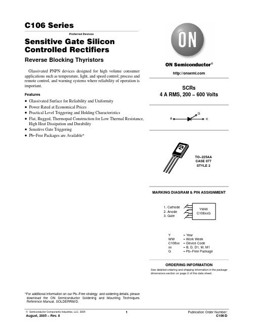
© Semiconductor Components Industries, LLC, 2005
1
August, 2005 − Rev. 8
Publication Order Number: C106/D
元器件交易网
C106 Series
MAXIMUM RATINGS (TJ = 25°C unless otherwise noted)
500 Units / Box
C106BG
TO−225AA (Pb−Free)
500 Units / Box
C106D
TO−225AA
500 Units / Box
C106DG
TO−225AA (Pb−Free)
500 Units / Box
C106D1*
TO−225AA
500 Units / Box
C106D1G*
TO−225AA (Pb−Free)
500 Units / Box
C106M
TO−225AA
500 Units / Box
C106MG
TO−225AA (Pb−Free)
500 Units / Box
C106M1*
TO−225AA
500 Units / Box
C106M1G*
TO−225AA (Pb−Free)
IGT
VGRM VGT
VGD
Latching Current (VAK = 12 V, IG = 20 mA)
Holding Current (VD = 12 Vdc) (Initiating Current = 20 mA, Gate Open)
DYNAMIC CHARACTERISTICS
洛雷克Eco黑盒+系列安防录像机说明书

WATcH oVER YoUR WoRLDFROM ANYWHERE IN THE WORLDMoBILE SURVEILLANcEConnect and view your system on the go with your tablet or smartphone over a 3G/4G or WiFi network.†SIMPLE YET ADVANcEDRecord on a surveillance grade hard drive, designed for 24/7 operation providing weeks or even months of reliable recording.1SIMULTANEoUS MoNIToR VIEWING Connect to a TV, PC, or CCTV monitors with industry standard HDMI, VGA & BNC inputs. 2EASY SYSTEM NAVIGATIoNIntuitive menu options with simple icons allow for fast and efficient DVR programming.CONNECT WITH TABLET & SMARTPHONEVIEW & CONTROL WITH PC & MAC 24/7 RELIABLE RECORDINGHIGH DEFINITION HDMI OUTPUT AFFORDABLE PEACE OF MINDiPhone ®iPad ®Remote connectivity & compatibilitySEcURITY cAMERA SYSTEM16cHANNELS 8cAMERAS1TB600TVL RESoLUTIoN 90/60FT NIGHT VISIoN•H.264 video compression ¹•HDMI output (HDMI cable included for – simple connection to HDTVs) 2 •Real time recording: 8/16ch: (360x240), 4ch: (720x240) resolution •960H (960x480) recording resolution capable 3•Pentaplex operation - View, Record, Playback, Back Up & Remotely Control the system simultaneously•24/7 100% Duty cycle hard drive pre-installed•PTZ cameras supported (RS485). Remotely controlable through App •Exclusive LOREX Easy Connect Internet Set-up Wizard 4•Instant Mobile Viewing on compatible Smart phones & Tablets † •PC and Mac Compatible (Internet Explorer & Safari browsers)•Free LOREX DDNS (Dynamic Domain Name Service) for advanced remote connectivity at all times•Instant email alerts with snap shot attachment•Accurate Time Stamps with NTP & Daylight Savings TimeDIGITAL VIDEo REcoRDER:Series•Super Resolution with enhanced optics•BrightNight Viewing with enhanced lowlight image sensor•Night Vision up to 90/66ft (28/20m) away 5•Anti-glare feature ensures clear images under strong lighting conditions •Accurate colours with Lorex’s automatic light filtering technology• 3.6mm wide-angle lens captures a 78° Field of View (diagonal) 6•Vandal resistant design with cable pass through mounting bracket7FEATURESTRUE coLoRSSee accurate colors with Lorex’s automatic light filtering technology.VANDAL RESISTANT DESIGNProtective cable pass-through bracket and metal housing.VIEW YOUR WORLD -IN SUPER RESOLUTION.CLEAR vidEo dAY ANd NiGHTviEW WiTH BRiGHT-NiGHTWEATHERPRooF HoUSiNGA SUPER RESoLUTIoN PERSPEcTIVEView your world with improved detail, sharpness, and clarity day and night.HOME BUSINESS RETAIL COMMERCIALAmbient Lighting Total DarknessPLA YBAcKPlayback Channel 1~4 Adjustable(4 ch), 1~8 Adjustable (8 ch), 1~16Adjustable (16 ch)Playback Speed V ariable Max 16x Playback Players Backup Player Search By time & eventLog Search Up to 10,00,000 lines for motion detected, configurationchanges, connects/disconnects and video loss.Audio PlayY esSToRAGE & ARcHIVE StorageUp to 1 HDD’s (SA T A) Maximum Capacity Up to 2TBBackup Media USB Flash Drive & HDDBackup File Format H.264 file (A VI generator included)coNNEcTIVITY Easy ConnectLorex Auto Port Forward WizardSupported Operating Systems Windows ™ 8, 7, XP , VistaMac OSX Snow Leopard 10.6 or above BrowsersInternet Explorer & Safari 6.0Email notification T ext with snapshotInstant Smart Phone Compatibility † Smart Phone & Tablet Compatibility: iPad ®,iPhone ®, BlackBerry (supported model numbers: 9800, 9700, 9000), Android (version 1.5 & above), Windows Mobile (6.0, 6.5), Symbian 3rd & 5th generation phones DDNSFree Lorex DDNSSystem Configuration Full setup configuration over network PortsProgrammable by UserNetwork ProtocolTCP/IP / DHCP / UDP / DDNS / PPPoE Network Interface 10/100-Base-TX, RJ-45 Network Speed Control 48Kb ~ 8MB/sec.GENERAL Power Consumption Approx. 10 watts (No HDD Installed)Supply V oltage 100V AC-240V AC, 12VDC , 2A, 50/60Hz Unit Dimensions 11.81”/300mm x 8.66”/220mm x(W x D x H) 1.97”/50mmUnit W eight (KGs) 1.51s kg/3.33 Lbs Operating temperature 32° ~ 104° F / 0° ~ 40° C Humidity10 ~ 90% NCImage Sensor: 1/3” Color Image Sensor Video Format: NTSCEffective Pixels: H: 758 V: 488Resolution: 600 TV Lines Scan System: 2:1 Interlace Sync System: Internal S/N Ratio: 46.8dB (AGC Off)Iris: AESAES Shutter Speed: 1/60 ~ 1/100,000 Sec.Min. Illumination: 0.1 Lux without IR LED0 Lux with IR LEDVideo Output: Composite 1.0Vpp @75 ohm Lens / Lens Type: 3.6mm F1.2 / Fixed FOV (Diagonal): 78°T ermination: BNC Type IR LED Qty / Type: 24 pieces / 850nm Night Vision Range: 90ft (28m)/66ft (20m) Power Requirement: 12V DC ±10%Power Consumption: Max. 280mA (w/IR)Operating T emp. Range: 14° ~ 122°F / -10° ~ 50°C Operating Humidity Range:< 60% RH Environmental Rating: IP66W eight (including stand):0.6lbs / 0.3kg CAMERA (CVC7572PK4B):DVR (LH0161001H):SYSTEM Operating System Linux (embedded)Pentaplex Simultaneous View, Record, Playback, Backup & Remote MonitoringNumber of Channels 16Inputs/outputs Video IN 16 x 1Vp-p, CVBS, 75ohms, BNC Video OUT 1 x BNC VGA OUT Y esHDMI Y esAudio IN 4 Line in(RCA), G.711Audio OUT 1 line out(RCA), G.711USB Port 1 at the back for Mouse, 1 at the front for firmware upgrade & USB backup Alarm IN 8ch In Alarm OUT1ch Out Video Output Resolution 800x600, 1024x768, 1280x1024, 1440x900, HDMI (1920x1080)PTZ control RS-485 Pelco D & P ProtocolDisplay Live Display 1, 4, 9, 16Live Display Speed 480 NTSC, 400 P ALOSD ON/OFFSystem Navigation USB Mouse, IR Remote Controller Motion Area Setting Adjustable grid (30x44) NTSCAdjustable grid (36x44) P AL Sensitivity levels 8Firmware Upgrade Via USB device and Network User Authority By user groupTime Synchronization Auto time sync by NTP server REcoRDINGVideo Compression H.264 Audio Compression G.711Recording Resolution NTSc: D1 mode: 720x480(D1), 720x240(2CIF), 360x240(CIF) 960H: 960x480, 960x240, 480x240 P AL: D1 mode: 720x576(D1), 720x288(2CIF), 360x288(CIF)960H: 960x576, 960x288, 480x288Recording Speed: NTSc: D1 mode: 480fps @ CIF , 224fps @ D1 & 2CIF 960H : 480fps @ 480x240, 160fps @ 960x480 & 960x240 P AL: D1 mode: 400fps @ CIF , 192fps @ D1 & 2CIF960H: 400fps @ 480x240, 144fps @ 960x480 & 960x240Recording Resolution Setting Per camera for different resolutions Recording Quality Control 3 levelsRecording ScheduleBy hour, by day , by recording mode, by motion, by alarm, by chPre Recording Max. 10 Secs Post Recording Max. 5 Minutes Reliability W atch-Dog, Auto-recovery after power failure Covert VideoY esMoDEL coNFIGURATIoN PAcKAGE W x D x H Inches & mmWEIGHT cUBEUPc code LH016810B16 ch Eco Blackbox+ DVR, x 8 (600) TVL Cameras (CVC7572PK4B) x 1TB HDDBrown Box426mm x 335mm x 297mm/16.8” x 13.2” x 11.7”9.8 kg/21.65 lbs0.042475m / 1.50ft7-78597-01681-9INCLUDES16 ch DVR with Pre-Installed HDD, HDMI Cable, Remote Control, Power adapter, Mouse, Ethernet Cable, Documentation & Software CD, QSG, Instruction Manual, 8 x Cameras, 8 x Camera Stands, 8 x 60ft BNC/DC Extension Cables, 2 x 4 in 1 Camera Power Adaptors.© 2013 Lorex Technology Inc.As our product is subject to continuous improvement, Lorex Technology & subsidiaries reserve the right to modify product design, specifications &prices without notice and without incurring any obligation. E&OE.Lorex Technology Inc.250 Royal Crest CourtMarkham, Ontario, Canada L3R 3S11-230113DVR Inputs & outputs DISCLAIMERS:1. Recording time may vary based on recording resolution & quality, lighting conditions and movement in the scene.2. HDMI output (1920x1080) for high definition multi-channel live viewing only. High definition recording not supported, recording resolution is limited to a maximum of 960x480 per channel. Image quality and resolution is dependent on the type of camera connected to the DVR.3. When used with 960H compatible cameras. DVR is backwards compatible and supports different camera inputs: standard resolution and 960H.4. Requires a high speed internet connection and a router (not included).5. IR Illumination range under ideal conditions. Actual range and clarity may vary depending on scene/object reflection and camera application. Measurements are calculated using ambient lighting and total darkness conditions. Picture automatically switches to B&W delivering better clarity in ow light conditions.6. Field of view, diagonal. If light level is too low, camera will switch over to B/W for increased light sensitivity.7. Not intended for submersion in water. Installation in a sheltered location recommended.† Smart Phone & Tablet Compatibility: iPad ®, iPhone ®, BlackBerry (supported model numbers: 9800, 9700, 9000), Android (version 1.5 & above),Windows Mobile (6.0, 6.5), Symbian 3rd & 5th generation phones. Mobile phone data plan is required (not included). Router port forwarding required. For the latest compatibility list check as new models become available in the market.* BlackBox is used solely as a marketing term and does not imply that the product can survive fire or extreme conditions. Use product in accordance with the instructions provided.All trademarks belong to their respective owners. No claim is made to the exclusive right to use the trademarks listed, other than the trademarks owned by Lorex Technology Inc. We reserve the right to change models, configurations or specifications without notice or liability. Product may not be exactly as shown. Images are simulated.Product Information:16 channel DVR901 Elkridge Landing Road, Suite 100Linthicum, Maryland 21090,USA.DVRDimensions:cVc7572PK4B cAMERA。
Dell PowerEdge R515 系统 硬件用户手册说明书

Dell PowerEdgeR515系统硬件用户手册管制型号 E12S 系列和 E13S 系列管制类型 E12S002 和 E13S002注、小心和警告注:“注”表示可以帮助您更好地使用计算机的重要信息。
小心:“小心”表示如果不遵循说明,就有可能损坏硬件或导致数据丢失。
警告:“警告”表示可能会导致财产损失、人身伤害甚至死亡。
____________________本出版物中的信息如有更改,恕不另行通知。
© 2010 Dell Inc. 版权所有,翻印必究。
未经 Dell Inc. 书面许可,严禁以任何形式复制这些材料。
本文中使用的商标:Dell™、DELL 徽标和 PowerEdge™是 Dell Inc. 的商标。
Microsoft®、Windows®、MS-DOS®和 Windows Server®是 Microsoft Corporation 在美国和/或其它国家和地区的商标或注册商标。
本出版物中述及的其它商标和产品名称是指拥有相应商标和产品名称的公司或其制造的产品。
Dell Inc. 对其它公司的商标和产品名称不拥有任何所有权。
管制型号 E12S 系列和 E13S 系列管制类型 E12S002 和 E13S0022010 年 8 月Rev. A00目录1关于系统 (11)在启动期间访问系统功能 (11)前面板部件和指示灯 (12)LCD 面板部件(可选) (15)主屏幕 (16)Setup(设置)菜单 (17)View(视图)菜单 (17)硬盘驱动器指示灯显示方式 (18)背面板部件和指示灯 (19)连接可选外部设备的指南 (22)NIC 指示灯代码 (22)电源指示灯代码 (23)诊断指示灯(可选) (24)LCD 状态信息(可选) (26)解决 LCD 状态信息描述的问题 (36)删除 LCD 状态信息 (36)目录3系统信息 (37)警告信息 (50)诊断程序信息 (50)警报信息 (50)可能需要的其它信息 (51)2使用系统设置程序和UEFI引导管理器 (53)选择系统引导模式 (53)进入系统设置程序 (54)响应错误信息 (54)使用系统设置程序导航键 (54)系统设置程序选项 (55)主屏幕. . . . . . . . . . . . . . . . . 55Memory Settings(内存设置)屏幕 (57)Processor Settings(处理器设置)屏幕 (58)SATA Settings(SATA 设置)屏幕(可选) (59)Boot Settings(引导设置)屏幕 (60)Integrated Devices(集成设备)屏幕 (61)PCI IRQ Assignments(PCI IRQ 分配)屏幕 (62)Serial Communication(串行通信)屏幕 (63)Embedded Server Management(嵌入式服务器管理)屏幕 (64)Power Management(电源管理)屏幕 (64)System Security(系统安全保护)屏幕 (65)Exit (退出)屏幕 (67)4目录进入 UEFI 引导管理器 (68)使用 UEFI 引导管理器导航键 (68)UEFI 引导管理器屏幕 (69)UEFI Boot Settings(UEFI 引导设置)屏幕 (69)System Utilities(系统公用程序)屏幕 (70)系统密码和设置密码功能 (70)使用系统密码 (70)使用设置密码 (73)嵌入式系统管理 (74)底板管理控制器配置 (75)进入 BMC 设置模块 (75)iDRAC6 配置公用程序 (76)进入 iDRAC6 配置公用程序 (76)3安装系统组件 (77)建议使用的工具 (77)系统内部组件 (77)前挡板(可选) (80)卸下前挡板 (80)安装前挡板 (81)打开与合上系统护盖 (81)打开系统护盖 (81)合上系统护盖 (83)冷却导流罩 (84)卸下冷却导流罩 (84)安装冷却导流罩 (85)目录5硬盘驱动器 (85)卸下硬盘驱动器挡片 (85)安装硬盘驱动器挡片 (86)卸下硬盘驱动器 (86)安装硬盘驱动器 (87)从硬盘驱动器托盘中卸下硬盘驱动器 (88)将硬盘驱动器安装到硬盘驱动器托盘中 (89)内部硬盘驱动器 (89)卸下内部硬盘驱动器托架 (89)安装内部硬盘驱动器托架 (91)从内部硬盘驱动器托架上卸下内部硬盘驱动器 (91)将硬盘驱动器安装到硬盘驱动器托架中 (92)光盘驱动器(可选) (93)卸下光盘驱动器 (93)安装光盘驱动器 (94)冷却风扇 (95)卸下冷却风扇 (95)安装冷却风扇 (98)电源设备 (99)卸下电源设备 (99)安装电源设备 (100)卸下电源设备挡片 (101)安装电源设备挡片 (101)系统内存 (101)内存模块安装一般原则 (102)模式特定原则 (103)安装内存模块 (104)卸下内存模块 (106)6目录扩充卡和扩充卡提升板 (107)扩充卡安装原则 (107)安装扩充卡 (109)卸下扩充卡 (111)卸下扩充卡提升板 (111)安装扩充卡提升板 (113)集成存储控制器卡 (114)卸下存储控制器卡 (114)安装存储控制器卡 (116)iDRAC6 Express 卡(可选) (117)安装 iDRAC6 Express 卡 (117)卸下 iDRAC6 Express 卡 (118)iDRAC6 Enterprise 卡(可选) (119)安装 iDRAC6 Enterprise 卡 (119)卸下 iDRAC6 Enterprise 卡 (121)VFlash 介质(可选) (122)安装 VFlash 介质卡 (122)卸下 VFlash 介质卡 (122)内部 USB 存储钥匙 (122)处理器 (123)卸下处理器 (123)安装处理器 (126)系统电池 (127)更换系统电池 (127)RAID 电池(可选) (130)卸下 RAID 电池 (130)安装 RAID 电池 (131)目录7控制面板部件— LED (131)卸下控制面板模块 LED 指示灯 (131)安装控制面板模块 LED 指示灯 (133)控制面板部件—LCD(可选) (133)卸下控制面板显示模块 (133)安装控制面板显示模块 (134)卸下控制面板部件 (134)安装控制面板部件 (136)SAS 背板 (136)卸下 SAS 背板 (136)安装 SAS 背板 (140)配电板 (141)卸下配电板 (141)更换配电板 (144)系统板 (145)卸下系统板 (145)安装系统板 (147)8目录4系统故障排除 (149)安全第一—为您和您的系统着想 (149)系统启动失败故障排除 (149)外部连接故障排除 (149)视频子系统故障排除 (150)USB 设备故障排除 (150)串行 I/O 设备故障排除 (151)NIC 故障排除 (151)受潮系统故障排除 (152)受损系统故障排除 (153)系统电池故障排除 (154)电源设备故障排除 (154)系统冷却问题故障排除 (155)风扇故障排除 (155)系统内存故障排除 (156)内部 USB 密钥故障排除 (158)光盘驱动器故障排除 (159)硬盘驱动器故障排除 (160)内部硬盘驱动器故障排除 (161)存储控制器故障排除 (162)扩充卡故障排除 (163)处理器故障排除 (164)目录95运行系统诊断程序 (167)使用 Online Diagnostics (167)嵌入式系统诊断程序功能 (167)何时使用嵌入式系统诊断程序 (168)运行嵌入式系统诊断程序 (168)嵌入式系统诊断程序检测选项 (168)使用 Custom Test(自定义检测)选项 (169)选择要检测的设备 (169)选择诊断程序选项 (169)查看信息和结果 (169)6跳线和连接器 (171)系统板跳线 (171)系统板连接器 (172)禁用已忘记的密码 (174)7获得帮助 (177)与 Dell 联络 (177)索引 (179)10目录关于系统在启动期间访问系统功能在启动期间,可以使用下列击键访问系统功能。
Christie Roadie 4K45 快速入門手冊说明书

快速入門手冊020-102664-01 Roadie 4K45注意版權與商標Copyright © 2017 Christie Digital Systems USA Inc. 保留一切權利。
所有品牌名稱與產品名稱分別屬於各擁有者的商標、註冊商標或商品名稱。
常見問題我們已盡最大努力確保準確性,但是有些情況下,產品或可用性變更可能未能及時在本文件中反映。
Christie 保留不經通知逕行變更規格的權利。
效能規格是代表性規格,但是可能隨Christie 無法控制的條件而異,例如,產品在正常工作條件下的維護。
效能規格是以本文件印刷時可用的資訊為依據。
Christie 對於此資料不提供任何保證,包含 (但不限於) 針對特定用途所隱含的適用保證。
Christie 對於此資料內含的錯誤不負任何責任,對於此資料的履行或使用而產生的意外或間接損害亦不負任何責任。
加拿大的製造場所通過 ISO 9001 與14001 認證。
保固產品受到 Christie 標準有限保固,相關的詳細資訊請聯絡 Christie 經銷商或 Christie。
除了 Christie 標準有限保固中可能規定的限制和與您的產品相關或適用於您產品的限制之外,本保固不包括:a.任一方向運送過程中造成的問題或損壞。
b.投影機燈泡 (請參閱 Christie 的獨家燈泡方案政策)。
c.使用超出建議燈泡壽命的投影機燈泡,或使用除 Christie 或 Christie 燈泡授權經銷商所提供之 Christie 燈泡以外的燈泡,所造成的問題或損壞。
d.本產品與非 Christie 設備組合 (例如分配系統、攝影機、DVD 播放器等) 或本產品與任何非 Christie 介面裝置一起使用所造成的問題或損壞。
e.使用從非 Christie 燈泡授權經銷商處所購買或取得之任何燈泡、更換零部件或元件所造成的問題或損壞,這些經銷商包括但不限於透過網際網路提供 Christie 燈泡、更換零部件或元件的任何經銷商 (可能從 Christie 取得授權經銷商的確認)。
淋浴机制 可汗 AZ. 51 BSV 超级 B 电影相机说明书

-Power System: film drive and power zooming operated by two micromotors ; entire zooming range is covered in approx. six
SG6-12
NOMENCLATURE
Rear Cover Opening Button Viewfinder
Eyepiece Adjustment Ring Footage Counter Film Transport Indicator Filming Speed Dial Switch Dial EE/Manual Aperture Control Ring
f/stop scale
• t.I
2.B 4 5.6
o
PRECISE AUTO EXPOSURE WITH THROUGH-THE-LENS SERVO EE METER a. No matter how slight the change in light while filming , the
AZ 518SV compensates for it automatically with its through-the-Iens Servo EE metering system. It assures perfect exposures under almost any conditions.
CODE NO. 3-30711-21