AGMA 97FTM7-1997
无人机机载武器的新发展

无人机机载武器的新发展作者:贺作豪来源:《无人机》2017年第08期9?11事件之后,美国通用原子航空系统公司(GA-ASI)生产的“捕食者”系列无人机开始在阿富汗执行日常武装侦察任务。
2011年10月7日,一架MQ-1“捕食者”无人机对目标实施了首次空中打击。
“捕食者”及其衍生型“死神”携带45kg的AGM-114“海尔法”激光制导空地导弹,这种导弹由主要用于有人直升机的“海尔法”经适配而成。
“捕食者”系列无人机还携带从有人机武器经适配而来的其他武器,如GBU-12“宝石路”Ⅱ、“杰达姆”(JDAM)和AGM-176“格里芬”(Griffin)。
续航时间长是无人机相对有人作战飞机的主要优势之一,用无人机能够实现纵深侦察打击,因此,发展尺寸小、重量轻和功耗低的武器对无人机来说至关重要。
“狂暴”泰雷兹英国公司的“轻型多用途导弹”(LMM)2015年开始在英国海军“野猫”(Wildcat)直升机上使用,该公司还销售这种武器供无人机使用。
这种小型武器具有2.2kg成形装药双重爆杀伤战斗部,可打击的目标范围很宽,包括户外人员、轻装甲车和中等装甲车等。
最初型LMM有动力装置,后来发展的自由落体式LMM,即FFLMM,是一种无动力滑翔型导弹。
FFLMM重6kg,其战斗部重2.2kg,适用于Ⅲ类和Ⅳ类无人机。
按泰雷兹公司与美国德事隆系统公司(Textron)的协议,被称为“狂暴”的FFLMM已在德事隆系统公司的“影子”无人机上进行了试验。
与有动力的LMM相比,“狂暴”的主要优点是重量轻,只有6kg,而用火药筒推进的LMM 重16kg;而且“狂暴”的隐身性能好,在发射时不产生闪光和声响。
这两种型别导弹的战斗部是通用的,但采用不同的制导方式。
LMM现在采用激光驾束(LBR)制导,而“狂暴”采用半主动激光(SAL)制导。
LBR制导需要在无人机上装有专用于对导弹进行制导的激光器。
其优点是激光器的功率很低,不会对被照射的目标发出警告,因此,没有已知的对抗措施。
美军M977重型扩大机动性战术车简介
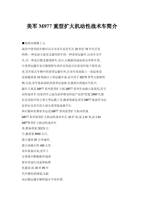
美军M977重型扩大机动性战术车简介●张煜高翔姚丁元战争中使用的车辆可以分为术车是美军在20世纪70年代开发两种,一种是前方进攻支援用的军的一种重型运输车.以该车为平车,另一种是后勤支援保障车,其台,可根据用途拓展为多种车型,中重型运输车是后勤保障车的代非常适合在恶劣环境下使用.此表.美军轮式车辆中的重型运输车外,在该车尾部装上一套起重设是指载质量10吨级以上的运输车备,还可用于M270型等火箭弹的辆.目前,美军装备部队的重型运装卸.在我国台湾地区军队中,输车主要是M977系列重型扩大机M977系列车也被大量使用,其号动性战术车.该系列车已成为驻伊称高科技产品的"雷霆2000"火箭拉克美陆军的主要大型运载工具,炮系统就是采用M977底盘作为运驻伊拉克美军的大部分重型装备载平台.和后勤补给都靠其运送.M977系列重型扩大机动性战M977系列重型扩大机动性战术车长10.17米,宽2.43米,高2.84M977I型扩大机动性战术车米,整备质量28123公斤,载质量9980公斤,最大速度88公里/d,时,最大续驶行程480公里.该车装备以来,美军十分重视不断根据作战需要对其进行改进和标准化建设.按20世90年代车辆发展规划,为提高后勤运输车辆性能并节省经费,美陆军与奥什柯什公司正对在役的M977系列重型扩大机动性战术车进行改造——1995年9月,奥什柯什公司接受了一份对123辆现役M977进行"扩展维修"的合同.现役的M977被解体后,送到新车装配线进行检修,并换装多个新型子系统,使该型车(增强型M977)成为美陆军机动性最强的一种运输车.增强型的M977重型扩大机动性战术车的主要改进是:增加了独立悬架,安装了中央轮胎充放气系统,使用了永久性润滑部件.使用独立悬架后,车辆上弹簧的可供使用行程比原来的设计标准增加了1倍,乘员和货物更加平稳,车辆的牵引力和离地间隙也有所增大,涉水深度由1.2米提高到1.5米.中央轮胎充放气系统可供驾驶员在任何条件下将车辆性能调整到最佳状态.永久性润滑系统(包括传动轴,球铰接件和控制臂枢轴)确保了车辆更好的野外使用性能,并能节省维修保养费用.口栏目编辑:王广仁QICHEYUNYONG2005年?筹1期?总筹147期一。
IEEE标准列表
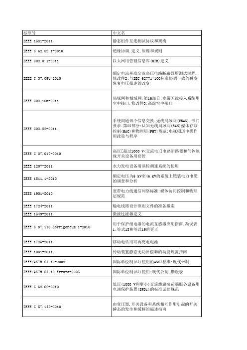
IEEE NESCIR551-2009
IEEE NESCIR550-2008 IEEE NESCIR549-2008 IEEE NESCIR548-2009 IEEE NESCIR547-2008 IEEE NESCIR546-2007 IEEE NESCIR545-2007 IEEE NESCIR544-2007 IEEE N42.48-2008
IEEE 1636.2-2010
IEEE 1609.4-2010 IEEE 1410-2010 IEEE C 63.10-2009 IEEE C 57.19.00 Errata-2010 IEEE C 57.12.00-2010 IEEE C 37.90.1 Errata-2003 IEEE C 37.46-2010 IEEE C 37.239-2010 IEEE C 37.13.1a-2010 IEEE 82 Errata-2009
第38节:法规384C设备接地与连接
第21节.法规215C1非载流部件的一般要求.总论
说明.第21节:电路、支撑结构和设备的接地 215C5b规则的一般要求.非流动运输部分
第21节:法规215C1接地电路、支持结构和设备的 一般要求.非载流部件.总论
第26节:强度要求 说明.第1节:现有设备的国家电气安全规程规则 013B3应用(2007版本,第2页)(26-3-2009) IR548
应用在电力输电和配电系统中的大功率电子器件 (1 MW或更大)控制结构用指南
38 kV以上高架配电系统野生动物防护设施的电 气,机械和耐用性能测试指南
降低鸟类引起的断电指南
AGMA Standards-美国齿轮标准
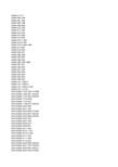
AGMA 217.01AGMA 900-H06AGMA 901-A92AGMA 904-C96AGMA 908-B89AGMA 910-C90AGMA 911-A94AGMA 912-A04AGMA 913-A98AGMA 914-B04AGMA 915-1-A02AGMA 915-2-A05AGMA 915-3-A99-1999AGMA 917-B97AGMA 918-A93AGMA 920-A01AGMA 922-A96AGMA 923-B05AGMA 925-A03AGMA 926-C99-1999AGMA 927-A01AGMA 930-A05AGMA 931-A02AGMA 932-A05AGMA 933-B03AGMA 935-A05AGMA 938-A05AGMA ISO 10064-1AGMA ISO 10064-2AGMA ISO 10064-5-A06 AGMA ISO 14179-1ANSI/AGMA 1003-G93 (R1999) ANSI/AGMA 1006-A97 (R2003) ANSI/AGMA 1010-E95 (R2004) ANSI/AGMA 1012-2005ANSI/AGMA 1102-A03ANSI/AGMA 1106-A97 (R2003) ANSI/AGMA 2000-A88ANSI/AGMA 2001-D04ANSI/AGMA 2002-B88 (R1996) ANSI/AGMA 2003-B97 (R2003) ANSI/AGMA 2004-B89 (R2006) ANSI/AGMA 2005-D03ANSI/AGMA 2007-C00ANSI/AGMA 2008-C01ANSI/AGMA 2009-B01ANSI/AGMA 2011-A98ANSI/AGMA 2015-1-A01ANSI/AGMA 2015-2-A06ANSI/AGMA 2101-D04ANSI/AGMA 2111-A98ANSI/AGMA 2116-A05ANSI/AGMA 6000-B96 (R2002) ANSI/AGMA 6001-D97 (R2003) ANSI/AGMA 6002-B93 (R2001) ANSI/AGMA 6004-F88 (R1996)ANSI/AGMA 6005-B89 (R1996) ANSI/AGMA 6008-A98ANSI/AGMA 6011-I03ANSI/AGMA 6013-A06ANSI/AGMA 6022-C93 (R2000) ANSI/AGMA 6023-A88 (R2000) ANSI/AGMA 6025-D98ANSI/AGMA 6033-B98ANSI/AGMA 6034-B92 (R1999) ANSI/AGMA 6035-2002ANSI/AGMA 6113-A06ANSI/AGMA 6123-A06ANSI/AGMA 6133-B98ANSI/AGMA 6135-2002ANSI/AGMA 9000-C90 (R2001) ANSI/AGMA 9001-B97 (R2003) ANSI/AGMA 9002-B04ANSI/AGMA 9003-A91 (R1999) ANSI/AGMA 9004-A99ANSI/AGMA 9005-E02ANSI/AGMA 9008-B00 (R2006) ANSI/AGMA 9009-D02ANSI/AGMA 9112-A04ANSI/AGMA ISO 1328-1ANSI/AGMA ISO 1328-2ANSI/AGMA ISO 18653-A06ANSI/AGMA/AWEA 6006-A03 Supplemental Tables for AGMA 2015 AGMA 6006-A03ANSI/AGMA 6009-A00ANSI/AGMA 6109-A00ANSI/AGMA 6110-F97 (R2003)Information Sheet - Gear Scoring Design for Aerospace Spur and Helical Power GearsStyle Manual for the Preparation of Standards, Information Sheets and Editorial ManualsA Rational Procedure for the Preliminary Design of Minimum Volume GearsMetric UsageInformation Sheet - Geometry Factors for Determining the Pitting Resistance and Bending Strength of Spur, HelicFormats for Fine-Pitch Gear Specification DataDesign Guidelines for Aerospace GearingMechanisms of Gear Tooth FailureMethod for Specifying the Geometry of Spur and Helical GearsGear Sound Manual - Part I: Fundamentals of Sound as Related to Gears; Part II: Sources, Specifications and Levels of G Inspection Practices - Part 1: Cylindrical Gears - Tangential MeasurementsInspection Practices - Part 2: Cylindrical Gears - Radial MeasurementsInspection Practices - Gear Blanks, Shaft Center Distance and Parallelism"Design Manual for Parallel Shaft Fine-Pitch GearingA Summary of Numerical Examples Demonstrating the Procedures for Calculating Geometry Factors for Spur an Materials for Plastic GearsLoad Classification and Service Factors for Flexible CouplingsMetallurgical Specifications for Steel GearingEffect of Lubrication on Gear Surface DistressRecommended Practice for Carburized Aerospace GearingLoad Distribution Factors - Analytical Methods for Cylindrical GearsCalculated Bending Load Capacity of Powder Metallurgy (P/M) External Spur GearsCalibration of Gear Measuring Instruments and Their Application to the Inspection of Product GearsRating the Pitting Resistance and Bending Strength of Hypoid GearsBasic Gear GeometryRecommendations Relative to the Evaluation of Radial Composite Gear Double Flank TestersShot Peening of GearsCylindrical Gears - Code of Inspection Practice - Part 1: Inspection of Corresponding Flanks of Gear TeethCylindrical Gears - Code of Inspection Practice - Part 2: Inspection Related to Radial Composite Deviations, Runout, Tooth Code of Inspection Practice - Part 5: Recommendations Relative to Evaluation of Gear Measuring InstrumentsGear Reducers - Thermal Capacity Based on ISO/TR 14179-1Tooth Proportions for Fine-Pitch Spur and Helical GearingTooth Proportions for Plastic GearsAppearance of Gear Teeth - Terminology of Wear and FailureGear Nomenclature, Definitions of Terms with SymbolsTolerance Specification for Gear HobsTooth Proportions for Plastic Gears (Metric Version of ANSI/AGMA 1006-A97)Gear Classification and Inspection Handbook - Tolerances and Measuring Methods for Unassembled Spur and H Fundamental Rating Factors and Calculation Methods for Involute Spur and Helical Gear TeethTooth Thickness Specification and MeasurementRating the Pitting Resistance and Bending Strength of Generated Straight Bevel, Zerol Bevel and Spiral Bevel Gear Teeth Gear Materials and Heat Treatment ManualDesign Manual for Bevel GearsGears - Surface Temper Etch Inspection After GrindingAssembling Bevel GearsBevel Gear Classification, Tolerances and Measuring MethodsCylindrical Wormgearing Tolerance and Inspection MethodsAccuracy Classification System - Tangential Measurements for Cylindrical GearsAccuracy Classification System - Radial Measurements for Cylindrical GearsFundamental Rating Factors and Calculation Methods for Involute Spur and Helical Gear Teeth (Metric Edition) Cylindrical Wormgearing Tolerance and Inspection Methods (Metric)Evaluation of Double Flank Testers for Radial Composite Measurement of GearsSpecification for Measurement of Linear Vibration on Gear UnitsDesign and Selection of Components for Enclosed Gear DrivesDesign Guide for Vehicle Spur and Helical GearsGear Power Rating for Cylindrical Grinding Mills, Kilns, Coolers, and DryersPower Rating for Helical and Herringbone Gearing for Rolling Mill ServiceSpecifications for Powder Metallurgy GearsSpecification for High Speed Helical Gear UnitsStandard for Industrial Enclosed Gear DrivesDesign Manual for Cylindrical WormgearingDesign Manual for Enclosed Epicylic Gear DrivesSound for Enclosed Helical, Herringbone, and Spiral Bevel Gear DrivesMarine Propulsion Gear Units, Part 1 - MaterialsPractice for Enclosed Cylindrical Wormgear Speed Reducers and GearmotorsDesign, Rating and Application of Industrial Globoidal WormgearingStandard for Industrial Enclosed Gear Drives (Metric Edition)Design Manual for Enclosed Epicyclic Gear DrivesMaterials for Marine Propulsion GearingDesign, Rating and Application of Industrial Globoidal Wormgearing (Metric Edition)Flexible Couplings - Potential Unbalance ClassificationFlexible Couplings - LubricationBores and Keyways for Flexible Couplings (Inch Series)Flexible Couplings - Keyless FitsFlexible Couplings - Mass Elastic Properties and Other CharacteristicsIndustrial Gear LubricationFlexible Couplings - Gear Type - Flange Dimensions, Inch Series (Also listed as 9008-B99)Flexible Couplings - Nomenclature for Flexible CouplingsBores and Keyways for Flexible Couplings (Metric Series)Cylindrical Gears - ISO System of Accuracy - Part 1: Definitions and Allowable Values of Deviations Relevant to Correspon Cylindrical Gears - ISO System of Accuracy - Part 2: Definitions and Allowable Values of Deviations Relevant to Radial Co Gears - Evaluation of Instruments for the Measurement of Individual GearsDesign and Specification of Gearboxes for Wind TurbinesAccuracy Classification System - Tangential Measurement Tolerance Tables for Cylindrical GearsStandard for Design and specification of Gearbox for Wind Turbines (Spersedes AGMA 921 - A97)Standard for Gearmotor, Shaft Mounted and Screw Conveyor DrivesStandard for Gearmotor, Shaft Mounted and Screw Conveyor Drives (metric version)Spur, Helical, Herringbone, and Bevel Enclosed DrivesAGMA Technical CommitteeAGMA Technical CommitteeAGMA Technical CommitteeAGMA Technical CommitteeAGMA Technical CommitteeAGMA Technical Committeecifications and Levels of Gear Sound; Part III: Gear Noise ControlAGMA Technical CommitteeAGMA Technical CommitteeDeviations, Runout, Tooth Thickness and BacklashInstrumentsAGMAAGMASpiral Bevel Gear TeethAGMAAGMAAGMAMetric Edition)AGMAAGMAAGMAAGMAAGMAAGMAAGMAns Relevant to Corresponding Flanks of Gear Teethns Relevant to Radial Composite Deviations and Runout Information in GE libraries while not listed herelisted in sheet ver3 while missed in ver4listed in sheet ver3 while missed in ver4listed in sheet ver3 while missed in ver4AGMA+217.01.pdf46 AGMA+900-H06.pdf30 AGMA+901-A92.pdf42 AGMA+904-C96.pdf42 AGMA+908-B89.pdf84 AGMA+910-C90.pdf51 AGMA+911-A94.pdf96 AGMA+912-A04.pdf70 AGMA+913-A98.pdf58 AGMA+914-B04.pdf76 AGMA+915-1-A02.pdf105 AGMA+915-2-A05.pdf47 AGMA+915-3-A99-1999.pdf42 AGMA+917-B97+.pdf84 AGMA+918-A93.pdf68 AGMA+920-A01.pdf58 AGMA+922-A96.pdf42 AGMA+923-B05.pdf79 AGMA+925-A03.pdf69 AGMA+926-C99-1999.pdf48 AGMA+927-A01.pdf69 AGMA+930-A05.pdf83 AGMA+931-A02.pdf63 AGMA+932-A05.pdf60 AGMA+933-B03.pdf37 AGMA+935-A05.pdf40 AGMA+938-A05.pdf45 AGMA+ISO+10064-1.pdf75 AGMA+ISO+10064-2.pdf55 AGMA+ISO+10064-5-A06.pdf145 AGMA+ISO+14179-1.pdf69 ANSI+AGMA+1003-G93+(R1999).pdf68 ANSI+AGMA+1006-A97+(R2003).pdf68 ANSI+AGMA+1010-E95+(R2004).pdf96 ANSI+AGMA+1012-2005.pdf82 ANSI+AGMA+1102-A03.pdf82 ANSI+AGMA+1106-A97+(R2003).pdf62 ANSI+AGMA+2000-A88.pdf140 ANSI+AGMA+2001-D04.pdf167 ANSI+AGMA+2002-B88+(R1996).pdf90 ANSI+AGMA+2003-B97+(R2003).pdf145 ANSI+AGMA+2004-B89+(R2006).pdf96 ANSI+AGMA+2005-D03.pdf167 ANSI+AGMA+2007-C00.pdf37 ANSI+AGMA+2008-C01.pdf68 ANSI+AGMA+2009-B01.pdf101 ANSI+AGMA+2011-A98.pdf84 ANSI+AGMA+2015-1-A01.pdf84 ANSI+AGMA+2015-2-A06.pdf40 ANSI+AGMA+2101-D04.pdf140 ANSI+AGMA+2111-A98.pdf74 ANSI+AGMA+2116-A05.pdf38 ANSI+AGMA+6000-B96+(R2002).pdf73 ANSI+AGMA+6001-D97+(R2003).pdf84 ANSI+AGMA+6002-B93+(R2001).pdf68 ANSI+AGMA+6004-F88+(R1996).pdf84ANSI+AGMA+6005-B89+(R1996).pdf79 ANSI+AGMA+6008-A98.pdf56 ANSI+AGMA+6011-I03.pdf95 ANSI+AGMA+6013-A06.pdf159 ANSI+AGMA+6022-C93+(R2000).pdf73 ANSI+AGMA+6023-A88+(R2000).pdf84 ANSI+AGMA+6025-D98.pdf79 ANSI+AGMA+6033-B98.pdf84 ANSI+AGMA+6034-B92+(R1999).pdf56 ANSI+AGMA+6035-2002.pdf79 ANSI+AGMA+6113-A06.pdf135 ANSI+AGMA+6123-A06.pdf140 ANSI+AGMA+6133-B98.pdf74 ANSI+AGMA+6135-2002.pdf74 ANSI+AGMA+9000-C90+(R2001).pdf62 ANSI+AGMA+9001-B97+(R2003).pdf42 ANSI+AGMA+9002-B04.pdf55 ANSI+AGMA+9003-A91+(R1999).pdf51 ANSI+AGMA+9004-A99.pdf69 ANSI+AGMA+9005-E02.pdf84 ANSI+AGMA+9008-B00+(R2006).pdf38 ANSI+AGMA+9009-D02.pdf49 ANSI+AGMA+9112-A04.pdf53 ANSI+AGMA+ISO+1328-1.pdf63 ANSI+AGMA+ISO+1328-2.pdf42 ANSI+AGMA+ISO+18653-A06.pdf75 ANSI+AGMA+AWEA+6006-A03.pdf208 Supplemental+Tables+for+AGMA+20137。
国外军用电子元器件质量等级与国内对应一览表

国外军用电子元器件质量等级与国内对应一览表为了保证元器件的质量,我国制定了一系列的元器件标准。
在上世纪70年代末期制定了“七专”7905技术协议和80年代初制定了“七专”8406技术协议,已具备了军用器件标准的雏形,但标准是在改革开放之前制定的,有很多局限性,很难与国际接轨。
从80年代开始,我国标准化部门参照了美国军用标准(MIL)体系建立了GJB体系,元器件的标准有规范、标准、指导性文件等三种形式。
一、国内军用元器件质量分级二、美国军标质量等级体系:MIL-PRF-19500半导体器件试验总规范(依次低→高等级)单片微电路规范(依次低→高等级)B-2级:不完全符合MIL-STD-883的节的要求,并按照政府批准文件,包括卖方等效的B级要求进行采购。
B-1级:完全符合MIL-STD-883(微电子器件试验方法和程序)的节所要求,并按照标准军用图样(SMD –Standard Microcicuit Drawing),国防电子供应中心(DESC –DefenceElectronic Supply Center)图样或政府批准的其它文件进行采购。
即通常称883级,器件上有5962 –xxx号。
S-1级:完全按照MIL-STD-975(NASA标准的电子电气和机电源器件目录)或MIL-STD-1547(航天飞行器和运载火箭用元器件、材料和工艺技术要求)进行采购,并有采购机关的规范批准。
MIL-PRF-38534D混合集成电路规范(依次低→高等级)电阻、电容、电感元件MIL 标准中有可靠性指标的元件失效等级分五级MIL 标准中有可靠性指标的失效率等级和失效率的对应关系三、欧空局元器件半导体分立器件:ESA/SCC(Europe SpaceAgency/Space Componet Cooperation)5000标准试验等级:B级、C级(从高到低)批接收等级:1级、2级、3级(从高到低)微电路:ESA/SCC(Europe SpaceAgency/Space Componet Cooperation)9000标准试验等级:B级、C级(从高到低)批接收等级:1级、2级、3级(从高到低)电阻、电容、电感器件:ESA/SCC(Europe SpaceAgency/Space Componet Cooperation)3000和4000标准试验等级:B级、C级(从高到低)批接收等级:1级、2级、3级(从高到低)四、国外军用元器件与我国军用元器件质量等级对应关系半导体分立器件质量等级对应关系微电路质量对应等级阻容电感失效率等级对应参考来源:融融网及网络资料。
三防手机 IP三防标准 AGM OEPT 标准户外三防手机标准

三防手机,包括户外爱好者选购户外手机时,时常会看到类似IPXX,例如IP67下面对三防手机的IP等级说明,帮助大家选购三防手机。
IP三防等级的意义:IP三防是Ingress Protection的缩写,IP三防等级针对电气设备外壳对异物侵入的防护等级,IP三防等级来源是国际电工委员会的标准IEC 60529,这个标准在2004年也被采用为美国国家标准。
IP等级的格式为IPXX,其中XX为两个阿拉伯数字,第一标记数字表示接触保护和外来物保护等级,第二标记数字表示防水保护等级,具体的防护等级可以参考下面的表格。
IP是国际用来认定防护等级的代号Ip等级由两个数字所组成,第一个数字表示防尘;第二个数字由表示防水,数字越大表示其防护等组长越佳。
IP X X第一位表示防固体侵入的级别:0.无防护1.防护大于50mm(如:手掌)2.大于12mm(如:手指)3.大于2.5mm(如:工具,导线)4.大于1.0mm(如:导线,细棍)5.防护足以造成危害的粉尘。
6. 完全防止灰尘侵入(密封),完善的防接触保护第二位表示防水侵入级别:0.无防护1.防滴水2.防下滴倾角小于15°的滴水3.防喷洒水,倾角<60°4.防护来自所有方向溅水5.防护来自所有方向水柱6.防护水溏或高压水柱7.侵于水中150mm~1m深,防水8.埋于水中,适合连续侵于水中,防水(例如:IP65即表示完全防尘,并可以防护来自所有方向的水柱)IP57级别以上的户外三防手机产品对手机的整机和内核密封设计以及生产工艺的要求极高,产品的不良率也一直居高不下。
目前市场能达到IP67级别或者说是准IP68级别的户外三防手机并不多。
AGM OEPT(Outdoor Environment Performance Test 户外环境全防测试)则是专门针对户外恶劣环境,定义户外三防手机。
AGM OEPT 标准规范了户外三防手机的各项防护指标,融合了IPXX密封标准,符合并全部通过 AGM OEPT 标准的可称之为真正的顶级三防手机或全防手机产品。
风力发电标准大全
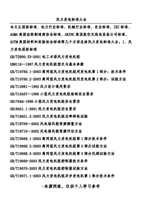
风力发电标准大全本文从国家标准、电力行业标准、机械行业标准、农业标准、IEC标准、AGMA美国齿轮制造商协会标准、ARINC美国航空无线电设备公司标准、ASTM美国材料和实验协会标准等几个方面总结风力发电标准大全。
1、风力发电国家标准GB/T19068.3-2003离网型风力发电机组第3部分风洞试验方法GB/T19069-2003风力发电机组控制器技术条件GB/T19070-2003风力发电机组控制器试验方法GB/T19071.1-2003风力发电机组异步发电机第1部分技术条件GB/T19071.2-2003风力发电机组异步发电机第2部分试验方法GB/T19072-2003风力发电机组塔架GB/T19073-2003风力发电机组齿轮箱GB/T19115.1-2003离网型户用风光互补发电系统第1部分:技术条件GB/T19115.2-2003离网型户用风光互补发电系统第2部分:试验方法2DL/T5067—1996风力发电场项目可行性研究报告编制规程DL/T5191—2004风力发电场项目建设工程验收规程DL/T5383-2007风力发电场设计技术规范3、风力发电机械行业标准JB/T6939.1—2004离网型风力发电机组用控制器第1部分:技术条件JB/T6939.2—2004离网型风力发电机组用控制器第2部分:实验方法JB/T6941—1993风力提水用拉杆泵技术条件JB/T7143.1-1993风力发电机组用逆变器技术条件JB/T7143.2-1993风力发电机组用逆变器试验方法JB/T7323—1994风力发电机组试验方法JB/T10398—2004离网型风力发电系统售后技术服务规范JB/T10399—2004离网型风力发电机组风轮叶片JB/T10400.1-2004离网型风力发电机组用齿轮箱第1部分:技术条件JB/T10400.2-2004离网型风力发电机组用齿轮箱第2部分:实验方法JB/T10401.1-2004离网型风力发电机组制动系统第1部分:技术条件JB/T10401.2-2004离网型风力发电机组制动系统第2部分:实验方法JB/T10402.1-2004离网型风力发电机组偏航系统第1部分:技术条件JB/T10402.2-2004离网型风力发电机组偏航系统第2部分:实验方法JB/T10403—2004离网型风力发电机组塔架45【机系统-安全要求】IEC61400-2风力发电机组第2部分:小型风力发电机的安全【Windturbinegeneratorsystems-Part2:Safetyofsmallwindturbines 风力发电机系统-小风机的安全】IEC61400-3Windturbinegeneratorsystems-Part3:Designrequirementsforoffshorewindturbines风机发电机系统-近海风机的设计要求IEC61400-11风力发电机噪声测试【Windturbinegeneratorsystems-Part11:Acousticnoisemeasurementte【【dsIEC/TS61400-23风力发电机组认证Windturbinegeneratorsystems-Part23:Full-scalestructuraltestingo frotorblades风力发电机系统-风轮结构测试IEC/TR61400-24Windturbinegeneratorsystems-Part24:Lightningprotection风力发电机系统-防雷保护IEC61400-25-1-2006Windturbines-Part25-1:Communicationsformonito ringandcontrolofwindpowerplants-Overalldescriptionofprinciplesa ndmodels风力涡轮机第25-1部分:风力发电厂监测和控制通信系统原理和模型总描述25-2风力涡25-5ISO/IEC81400-4Windturbinegeneratorsystems-Part4:Gearboxesfortur binesfrom40kWto2MWandlarger风机发电机系统-40kW到2MW或更大风机变速箱IEC61400-SERWindturbinegeneratorsystems-ALLPARTS风力发电机系统-所有部分6、风力发电AGMA美国齿轮制造商协会标准AGMA02FTM4-2002Multibody-System-SimulationofDriveTrainsofWind Turbines风力涡轮机的驱动齿轮组的多体系统仿真ANSI/AGMA6006-2004DesignandSpecificationofGearboxesforWindTurbi nes风力涡轮机齿轮箱的设计和规范7、风力发电ARINC美国航空无线电电9、风风ANSI/ASMEPTC42-1988风力机性能试验规程ASMEPIC20.3-1970汽轮发电机组用压力控制系统11、风力发电ASTM美国材料和实验协会标准ASTME1240-88风能转换系统性能的测试方法12、风力发电IEEE美国电气与电子工程师协会标准ANSI/IEEE67-2005涡轮发电机的操作维护指南ANSI/IEEE492-1999水利发电机运转和维护指南ANSI/IEEE1010-2006水利发电站的控制指南IEEE/ANSI1021-1988小型与公用电网互联的推荐规范13、风力发电AS澳21BS风力发电,DINEN61400-25-3-2007Windturbines-Part25-3:Communicationsformoni toringandcontrolofwindpowerplants-Informationexchangemodels(IEC 61400-25-3:2006);GermanversionEN61400-25-3:2007,textinEnglish 风力涡轮机。
融合多源数据与元胞传输模型的高速公路交通状态估计方法

第21卷第4期2023年12月交通运输工程与信息学报Journal of Transportation Engineering and InformationVol.21No.4Dec.2023文章编号:1672-4747(2023)04-0103-12融合多源数据与元胞传输模型的高速公路交通状态估计方法易术*,黄丹阳(四川智能交通系统管理有限责任公司,成都610200)摘要:针对高速公路管控和决策应对交通状态进行准确、可靠和精细化估计的需求,本文提出了一种基于多源数据+元胞传输模型(Multi-Source Data Cell Transmission Model,MD-CTM)的交通状态估计方法。
该方法针对传统CTM模型要求元胞长度必须一致的局限性,提出了一种元胞长度划分的优化方法,能够灵活调整元胞长度和数量。
同时,应用卡尔曼滤波技术,将ETC门架流量、稀疏视频检测器流量和样本车辆平均速度数据融合,并与CTM模型相结合,实现高速公路元胞级交通状态估计。
为了验证本文提出方法的有效性和准确性,我们利用VISSIM软件构建了长度5km的高速公路仿真场景。
仿真案例结果表明,本文提出的MD-CTM模型能够较为准确地反映不同流量需求下交通流状态的时空演化特征,且相较于CTM模型,其元胞密度估计精度提高12.59%~36.26%。
此外,本文选取了成都市绕城高速路段实际场景,对模型的运行效果进行了展示。
关键词:智能交通;交通状态估计;卡尔曼滤波;元胞传输模型;多源数据融合中图分类号:U495文献标志码:A DOI:10.19961/ki.1672-4747.2023.08.001Freeway traffic state estimation based on multi-source data andcell transmission modelYI Shu*,HUANG Dan-yang(Sichuan Intelligent Transport System Management Co.,Ltd.,Chengdu610200,China)Abstract:Accurate,reliable,and efficient traffic state estimation is essential for effective freeway management and decision-making.This study presents a traffic state estimation method called MD-CTM,which combines multi-source data and the cell transmission model(CTM).As the traditional CTM has limitations owing to fixed cell lengths,we propose a cell division approach that allows for flexible lengths and numbers.To enhance the accuracy of traffic state estimation,we utilize the Kal-man filtering technique to fuse different types of traffic data,including traffic flow from the electron-ic toll collection system and sparse video detectors,and an average link speed with the CTM to achieve cell-level traffic state estimation on freeways.To evaluate the performance of the proposed approach,we conducted simulations using VISSIM on a freeway section of5km.The simulation re-sults show that the proposed MD-CTM model improves the accuracy of cell density estimation by12.59%~36.26%compared with the CTM model.Furthermore,our model effectively captures thespatio-temporal evolution characteristics of traffic flow states under different traffic demand condi-收稿日期:2023-08-07录用日期:2023-08-25网络首发:2023-09-12审稿日期:2023-08-07~2023-08-09;2023-08-17~2023-08-25基金项目:国家重点研发计划项目(2021YFB1600100)作者简介:黄丹阳(1988—),男,硕士,高级工程师,研究方向为交通智能控制、内模与预测控制,E-mail:****************通信作者:易术(1970—),男,硕士,高级工程师,研究方向为交通工程、智慧交通,E-mail:****************引文格式:易术,黄丹阳.融合多源数据与元胞传输模型的高速公路交通状态估计方法[J].交通运输工程与信息学报,2023,21(4):103-114.YI Shu,HUANG Dan-yang.Freeway traffic state estimation based on multi-source data and cell transmission model[J].Journal of Transportation Engineering and Information,2023,21(4):103-114.104交通运输工程与信息学报第21卷tions.Moreover,a real-world scenario of Chengdu city is used to further demonstrate the effective-ness of our proposed approach.Key words:intelligent transportation;traffic state estimation;Kalman filter;cell transmission model;multi-source data fusion0引言高速公路交通状态估计是交通领域中的一个重要研究方向。
AGM-78 标准 反辐射导弹

AGM-78反辐射导弹一、概述AGM-78“标准”是美国通用动力公司于1966年开始研制的第二代反辐射导弹,1968年正式投入批量生产。
与第一代“百舌鸟”相比,“标准”反辐射导弹的射程更远、威力更大、抗干扰能力更强、导引头的频带更宽,并增加了目标位置和频率记忆功能。
即使目标雷达关机,该弹仍能按照关机前记忆的目标位置继续飞行,一旦目标雷达重新开机,它便可再次捕捉目标。
1、研制背景1964年由美国德州仪器研制的世界第一种反辐射导弹AGM—45“百舌鸟”服役,并于1965年投入越南战场实战使用。
在战争初期,美军用“百舌鸟”攻击越方57毫米高炮阵地和SA-2导弹系统的雷达,曾迫使这些雷达不敢轻易开机。
据统计,在使用“百舌鸟”前,越军击落一架美国飞机需发射10枚地空导弹,在使用“百舌鸟”后需发射70枚导弹才能击落一架美机。
但作为第一代反辐射导弹的典型代表,“百舌鸟”也有以下明显缺点:第一,导引头覆盖频段太窄。
虽然“百舌鸟”所有型号都采用通用的、可将天下尺寸降低到目标雷达波长1/4 以下的等角四臂平面螺旋天线,但导引头覆盖频段太窄,为了对付工作在不同频段的雷达不得不研制许多导引头,并在出击前根据已知情报选用。
“百舌鸟”早期型号依靠多达18 种导引头才覆盖了D~J 波段(1~20 吉赫兹),后期型在这方面改进也不显著,这是导致它的型号特别多的最重要原因。
第二,制导方式单一。
“百舌鸟”系列只能沿着雷达发出的电磁波飞向目标,而且在发射到击中目标的全过程中目标必须始终发射雷达波;一旦对方雷达采用关机等措施,导弹将失去制导信息来源而无法命中目标。
所以,在越南战争后期,北越军队抓住“百舌鸟”的这些破绽,使用不同频率的雷达组成防空网,让它顾此失彼,并在导弹来袭时紧急关机,使“百舌鸟”失去目标而纷纷落荒。
此后,一种能在瞬间改变工作频率的捷变频雷达也问世了,它使“百舌鸟”的命中率在1970 年下降到3%~6%。
第三,导引精度低、战斗部威力不足。
1997-FOIL AIRGAS BEARING TECHNOLOGY ~ AN OVERVIEW
The AMERICAN SOCIETY OF MECHANICAL ENGINEERS345 E. 47th St., New York, NY 10017Publication 97-GT-347FOIL AIR/GAS BEARING TECHNOLOGY ~ AN OVERVIEWGiri L. AgrawalR&D Dynamics CorporationBloomfield, CT 06002ABSTRACTThis paper summarizes the chronological progress of foil air bearings for turbomachinery during the last 25 years. Descriptions of various machines which are in production are provided. The foil bearing air cycle machine on the 747 aircraft has demonstrated an MTBF (mean time between failure) in excess of 100,000 hours. Many advantages of foil air bearings are noted. Various designs of foil air bearings presently in use and their relative merits are described. Analytical methods, their limitations, and their relationships with test results are noted. Descriptions of various machines built and tested in process fluids being gases, other than air, and cryogenic liquids are described. Conclusions are drawn that various high speed turbomachines including high temperature applications can be designed and developed using foil air bearings which will increase efficiency and reduce cost of these machines. INTRODUCTIONFoil air bearings have made significant progress during the last 25 years. Reliability of many high speed turbomachines with foil bearings has increased over tenfold compared to those with rolling element bearings. A high speed rotating machine called Air Cycle Machine (ACM) is the heart of the Environmental Control System (ECS) used on aircraft to manage cooling, heating and pressurization of the aircraft. Today, ACM for almost every new ECS system on military and civil aircraft and on many ground vehicles use foil air bearings. Old ECS systems with rolling element bearings are being converted to foil air bearings. The F-16 aircraft ACM used rolling element bearings from 1974 to 1982, but all aircraft built since 1982 use foil air bearings. The 747 aircraft ACM used rolling element bearings from 1970 to 1988. All aircraft built since 1988 have foil air bearings. ECS on the older model 737 aircraft have rolling element bearings, whereas ECS on new737 use foil air bearings. Many machines with working fluids other than air, such as helium, xenon, refrigerants, liquid oxygen and liquid nitrogen, have been built and successfully tested.WHY FOIL BEARINGS?The use of foil bearings in turbomachinery has several advantages.Higher Reliability - Foil bearing machines are more reliable because there are fewer parts necessary to support the rotative assembly and there is no lubrication needed to feed the system. When the machine is in operation, the air/gas film between the bearing and the shaft protects the bearing foils from wear. The bearing surface is in contact with the shaft only when the machine starts and stops. During this time, a coating on the foils limits the wear.No Scheduled Maintenance - Since there is no oil lubrication system in machines that use foil bearings, there is never a need to check and replace the lubricant. This results in lower operating costs.Soft Failure - Because of the low clearances and tolerances inherent in foil bearing design and assembly, if a bearing failure does occur, the bearing foils restrain the shaft assembly from excessive movement. As a result, the damage is most often confined to the bearings and shaft surfaces. Theshaft may be used as is or can be repaired. Damage to the other hardware, if any, is minimal and repairable during overhaul.Environmental Durability - Foil bearings can handle severe environmental conditions such as sand and dust ingestion. Largerparticles do not enter into the bearing flow path because of a reversed pitot design at the cooling flow inlet and smaller particles are continually flushed out of the bearings by the cooling flow. This ability to withstand contamination eliminates the need for filters in the airflow.High Speed Operation - Compressor and turbine rotors have better aerodynamic efficiency at higher speeds. Foil bearings allow these machines to operate at the higher speeds without any limitation as with ball bearings. In fact, due to the hydrodynamic action, they have a higher load capacity as the speed increases.Low and High Temperature Capabilities - Many oil lubricants cannot operate at very high temperatures without breaking down. At low temperature, oil lubricants can become too viscous to operate effectively. Foil bearings, however, operate efficiently at severely high temperatures, as well as at cryogenic temperatures.Process Fluid Operations - Foil bearings have been operated in process fluids other than air such as helium, xenon, refrigerants, liquid oxygen and liquid nitrogen. For applications in vapor cycles, the refrigerant can be used to cool and support the foil bearings without the need for oil lubricants that can contaminate the system and reduce efficiency.HISTORYGarrett AiResearch (now Allied Signal) has done the pioneering work on foil air bearings. Several laboratory and prototype machines were built in the mid 60’s. The first production ACM using foil air bearings was designed and developed for the DC-10 ECS system in 1969. Field experience proved that the unit was far more reliable then previous 727 ball bearing units. Further research and laboratory testing to increase load capacity and damping continued. In 1972, a 125 kw turbo-alternator-compressor (TAC) supported on foil bearings was built by AiResearch for NASA Lewis, which worked well. In 1974, under pressure from the Navy to increase the reliability of the A7E air cycle machine, AiResearch converted existing ball bearing machines to foil bearing machines on three A7E aircraft. These aircraft were flown by the Navy off the Coral Sea during the Vietnam War for evacuation of Americans from South Vietnam. These units worked extremely well and proved to be much more reliable than previous ball bearing units. As a result, after Vietnam was over, the Navy gave a contract to AiResearch to convert the entire fleet of A7E to foil bearing units. This program gave high confidence to AiResearch management in foil bearing technology even for a military aircraft. In 1976, when the F-18 program was launched by Northrop, AiResearch decided to proceed with foil air bearings from the start. The unit successfully passed vibration and shock load testing. This was the first military unit with foil air bearings to go into production.In 1978, AiResearch developed a small foil air bearing supported ACM for the commuter plane Cessna-550. This unit since then is also used on other aircraft e.g. EMB-120, ATR-42, ATR-72 and others. In 1979, a new commercial aircraft 767/757 was launched by Boeing. By now the success of foil air bearings was well known; hence Boeing required that ECS on 767/757 use foil air bearings. AiResearch successfully developed a foil air bearing supported ACM for 767/757. Based on the successful testing, they won the contract and went into production. In 1979AiResearch developed a foil air bearings supported ACM for Navy F-14 aircraft which was also flight tested on Air Force F-15 aircraft with some modifications. Later AiResearch, by making necessary modifications, used existing machines on various other ECS systems. They also developed a small foil air bearing supported machine for the M-1 tank.While substantial advancement in foil air bearing technology was being made by AiResearch in the 70’s, their competitor Hamilton Standard started lagging behind in ECS business. At the same time, Mechanical Technology Inc. (MTI), a research and development company, came up with their own concept of a foil bearing design called Hydresil. Hamilton signed a contract with MTI to use Hydresil bearings. Hydresil had comparable load capacity, but had low damping. Several ACM with Hydresil bearings were flight tested by Hamilton on 747 aircraft from 1975 to 1979. During flight testing those units lasted only four hours to fifty hours. In 1979, Hamilton launched their own program for foil bearing research. They came up with their own design concept and patented it. In 1982, Hamilton successfully flight tested a foil bearing ACM based on their own foil bearing design on F-16 aircraft. The same machine with minor changes went into production for B-1B aircraft and B-2 aircraft. Later the same machine was successfully flight tested on two F-18 aircraft. Based on successful flight test experience, the Navy qualified the machine for the F-18 without formal qualification testing. Hamilton also developed, qualified and produced a machine for L-1011 aircraft. Under pressure from various airlines, Boeing adopted the same machine with some changes for 747-400 aircraft which went into production in 1988. This machine has shown MTBF (mean time between failure) of over 100,000 hours. Between 1983 and 1988, Hamilton developed several other prototype machines supported on foil air bearings. In 1991, Hamilton developed, qualified and started producing a machine for SAAB 2000 aircraft. The same machine is being used for EMB-145 aircraft.In 1993, Hamilton developed, qualified and started producing the world’s first four-wheel ACM supported on foil air bearings for 777 aircraft. The unit passed 36,000 start-stop cycle to simulate a 30 year life.Various other companies such as Sunstrand, British Aerospace, ABG-Semca (France) and Tupolev (Russia) have done limited work on foil air bearing technology.FOIL BEARING TECHNOLOGYThe principle of an air or gas bearing is simple. As shown in Fig. 1, when two surfaces form a wedge, and one surface moves relative to the other surface, pressure is generated between the surfaces due to the hydrodynamic action of the fluid which carries load.Fig. 1: Principle of an Air BearingJournal BearingIn a journal bearing, the shaft deflects and a wedge is formed due to the eccentricity between the shaft center and the bearing center. The resulting hydrodynamic pressure generation is shown in Fig. 2. Even though, the principle of an air bearing is simple,application is complex. Usually running radial clearance between the shaft and the bearing is less than 0.0005 inch for a 2 inch diameter shaft running at 36,000 rpm. But the shaft growth due to temperature and centrifugal force could be 0.0020 in. Hence a bearing can not be made to work at various speeds and temperatures.In addition, damping is required to suppress any whirl instability,and there could be misalignment between various rotating parts and stationary parts. These problems are resolved by foil bearings.While stationary, there is a small amount of preload between the shaft and the bearing. As the shaft turns, a hydrodynamic pressure is generated, which pushes the foils away from the shaft and the shaft becomes completely airborne. This phenomenon occurs instantly during start-up at a very low speed. When the shaft is airborne, friction loss due to shaft rotation is very small. As the shaft grows, the foils get pushed further away keeping the film clearance relatively constant. In addition, foils provide coulomb damping due to relative sliding, which is essential for stability of themachine. Various concepts of foil bearings have been tested.Fig. 2: Hydrodynamic Pressure GenerationThe Multipad concept is shown in Fig. 3, which has been pursued by AiResearch since the days of the DC-10. Multiple pads form an iris and provide a preload when the shaft is not running.During starting, the iris expands and a cushion of air is formed between the bearing and the shaft. Later versions such as for 767/757 have a supportive spring behind each pad which increases the load capacity significantly. The top foil is coated with Teflon-Sor a polyimide coating to provide lubricity during starts and stops.Fig. 3: Multipad Foil Journal Bearing SchematicFigure 4 is a Reversed Multilayer journal bearing concept which has been pursued by Hamilton Standard in 747, B-1B, B-2,SAAB-2000, 777 and other aircraft. The single corrugated (bump)foil which has a bilinear spring characteristic is restrained in an axial keyway in the outer shell along one edge. The intermediate and top foils are attached to a key along one edge and are wound in opposite directions. The top foil has a thin coating which provides lubricity during startup and shutdown. As the shaft rotates, a wedge is formed due to the radial displacements of the shaft. Hydrodynamic action draws the working gas into the wedge where it is locally compressed. The corrugated foil acts as a spring which accommodates expansion, excursions and any misalignment. It also provides a flow path for the cooling air to remove parasitic heat from the bearing. In the Reversed Multilayer foil bearing, the adjacent foils move in opposite directions. The net result is that relative movement is additive, which in turn produces high coulombdamping.Fig. 4: Reversed Multilayer Foil Journal BearingSchematicFigure 5 is a Hydresil foil journal bearing. It has been pursued by Mechanical Technology Inc. (MTI). Both the bump foil and the foil are spot welded to the sleeve. Various versions have been patented. The load capacity of the Hydresil is comparable to the Multipad or Reversed Multilayer foil bearing, but it has lowdamping.Fig. 5: Hydresil Foil Journal Bearing SchematicThe damping characteristic of three types of bearings is shown in Fig. 6, where orbits are shown when 27 lbs. of shock load is applied to a 2 inch diameter shaft rotating at 36,000 rpm. It is obvious that the Reversed Multilayer concept is the most stable andit is least affected by shock loads.Fig. 6: Orbits of Various Foil Journal Bearings under 27 lbs. of Shock LoadEven though Reversed Multilayer concept has high damping,the foils have a tendency to protrude like a telescope during assembly. In addition, manufacturing is costly because all bendsnear the keyway have tight tolerances. A new concept called Reversed Multipad shown in Fig. 7 has been patented by R&D Dynamics Corporation. It has benefits of both Multipad and Reversed Multilayer designs. It has high damping as well as it requires low preload. Lower preload makes the machine start at alower torque. Due to multipad design, the tolerances are not tight.Fig. 7: Reversed Multipad Foil Journal Bearing SchematicThrust BearingsThrust bearings withstand axial loads in a rotating machinery.They work on the same hydrodynamic principle as journal bearings shown in Fig. 1. In a journal bearing the wedge action comes from eccentricity between the center of the rotating shaft and the center of the bearing itself, whereas in a thrust bearing the wedge is built in taking into account any deflection due the axial load.A radial spring type thrust bearing is shown in Fig. 8. It was invented by AiResearch and has been followed since 1970 when first used for the DC-10. There are multiple radial springs which transfer the load to the housing. Foils between the springs deflect under pressure forming the wedge required for the hydrodynamic action. During the last 20 years many versions of the same design,usually for the manufacturing reasons mostly by AiResearch, have been used. In some designs instead of a separate spring being spot welded to the main bearing plate, it is formed by chemical etching out of the bearing plate. It reduces manufacturing cost, butsomewhat compromises performance in some instances.Fig. 8: Radial Spring Foil Thrust BearingA dual spring thrust bearing is shown in Fig. 9. It was invented by Hamilton Standard. In this concept the bearing consists of two washer shaped plates similar to radial spring bearings. The coated pads, welded to the top plate, are supported on stiff bump foil springs to optimize the wedge shape required for load capacity and lift-off. The bottom plate has several softer bump foil springs welded to it, required to optimize the overall spring rate and damping of the bearing. The dual spring rate thrust bearings have approximately 15% higher load capacity than the radial springbearings, but they are more expensive to manufacture.Fig. 9: Dual Spring Foil Thrust BearingCoatings Both journal and thrust bearings apply a small amount of preload on the shaft when the machine is not running. The foil face which is touching the shaft is coated for lubricity during startup and shutdown. A typical DC-10, machine which runs at 48,000 rpm, is fully airborne at about 2,000 rpm. Several foil coatings are used.Most commercial aircraft use Teflon-S made by DuPont which isgood up to 475o F. Most military aircraft ACM use a polyimide coating, whose basic research was performed by NASA Lewis. Both AiResearch and Hamilton have modified the basic formula and the application process to suit their needs. The coating is good up to 700o F. Extensive high temperature coating research has been performed, mostly by NASA Lewis, Air Force Wright Laboratory, AiResearch (Phoenix Division) and Mechanical Technology Inc. A partial list of various coatings, which have been considered, is given below:Coating ProcessFOIL:BN/Pt, BN/Pd Electrophoretic DepositionBN/Pt Chemical Vapor InfiltrationBN/SiO2, BN/ZrO2 Sol GelBN/Ni-Cr,ZrO2/Ni-Cr Mechanical AlloyingBN/Ni Electroless DepositionCr2O3 SputteringTiC SputteringA12O3 SputteringTiN SputteringTribaloy-400 SputteringJOURNAL:NASA PS212 Plasma SprayKAMAN DES Chemically AdherentTiAlN/TiA1 SputteringWC-9Co D-GunCr2O3-4OCr D-GunAnalysis and TestingThe analysis of foil air bearings requires simultaneous solutions or iteration methods to solve foil elasticity equations and fluid hydrodynamic equations. Foil elasticity equations are nonlinear and involves large deformation theory. A foil can deform as much as five times its own thickness. Hence most finite element or finite difference methods, do not provide satisfactory results. Hydrodynamic equations are nonlinear Reynolds’ equations with continuously changing boundary conditions. Many papers analyzing foil bearings have been published. In some papers, predicted results vary as much as 500% from the actual test results. What seems to work and provide reasonable results are semi-empirical methods. Sufficient test data are collected by varying geometrical parameters and test parameters of the bearing. Results are correlated using a multiple regression method. Then a model is prepared using coefficients of the multiple regression analysis. Hydrodynamic equations are solved using the preferred final geometry. Then an inverse method is used to design the foil geometry in the unloaded position. In the above described procedure, the complex problem is decoupled into many simple problems using both analytical methods and the test results.The above described approach has been used both by AiResearch (Los Angeles) and Hamilton Standard to design and develop successfully many foil air bearing machines which are flying today. Others have taken more conventional approach and have not succeeded. Design of the machine parameters such as static and dynamic loads, critical speed, thrust loads, rotor clearance, seals, cooling flow etc. must be correlated with the design of the foil air bearings.A satisfactory design method requires reliable test data. Successful test rigs to test journal bearings, thrust bearings and coatings have been designed and developed. Typical rigs presently being used at R&D Dynamics Corporation are shown in Figs. 10, 11and 12.Fig. 10: Journal Bearing Test Rig(R&D Dynamics Corp.)Fig. 11: Thrust Bearing Test Rig(R&D Dynamics Corp.)Fig. 12: Coating Wear Test Rig(R&D Dynamics Corp.)APPLICATIONSDC-10 - The DC-10 was the first production foil air bearing machine. It was designed and developed by AiResearch and went into production in 1970. The same machine is also used for Airbus A-300. A photograph of the machine is shown in Fig. 13. The rotating assembly has three rotors: a turbine, a compressor and a fan. The machine runs at 48,000 rpm. To date, over 80 millionhours have been accumulated on this machine.Fig. 13: DC-10 Foil Bearing Air Cycle Machine(Developed by AiResearch)F-18 - The F-18 is the first military production machine aftersuccessful modifications of the A7E machine from ball bearings to air bearings. The F-18 machine was designed and developed by AiResearch in 1976. A cross section of the machine is shown in Fig. 14. It has two rotors: a turbine and a compressor. Themachine runs at about 95,000 rpm.Fig. 14: F-18 Foil Bearing Air Cycle Machine(Developed by AiResearch )Cessna-550 - In 1977 AiResearch developed a small two-wheel air cycle machine for commuter aircraft such as the Cessna-550.The machine is shown in Fig. 15. It runs at 105,000 rpm. The same machine is being used for EMB-120, ATR-42 and ATR-72 aircraftwith minor modifications.Fig. 15: Cessna-550 Foil Bearing Air Cycle Machine (Developed by AiResearch)F-15/F-14 - Following success of the F-18, AiResearch developed a slightly larger two-wheel air cycle machine for F-15 aircraft in 1977. The same machine with slight modifications was used for F-14 aircraft in 1978. Photograph of F-14 machine is shown in Fig.16.Fig. 16: F-14 Foil Bearing Air Cycle Machine(Developed by AiResearch)767/757 - The 767/757 aircraft was launched by Boeing in 1979. Knowing the success of DC-10 ACM, Boeing required that 767/757 ACM must have foil air bearings. This was the first aircraft where the customer required a foil bearing ACM. Cross section of the machine developed by AiResearch is shown in Fig. 17. It is also a three-wheel machine like the DC-10, but the design is muchsimpler.Fig. 17: 767/757 Foil Bearing Air Cycle Machine(Developed by AiResearch)F-16 - The F-16 aircraft is built by General Dynamics. Its production was started in 1974. An air cycle machine with a ball bearing design was built by Hamilton Standard. In 1982, due to additional electronics on the aircraft, the Air Force required a new air cycle machine. AiResearch modified the existing F-18 machine and qualified for F-16 aircraft, which is now in production. A photoof the F-16 ACM is shown in Fig. 18.Fig. 18: F-16 Foil Bearing Air Cycle Machine(Developed by AiResearch)M1A1 - AiResearch also developed a foil air bearing air cycle machine for the M1A1 tank environmental control system. The machine has a turbine and a fan on a common shaft. The machine worked well during the last Gulf War in spite of heavy sand and dustin the desert. The machine is shown in Fig. 19.Fig. 19: M1A1 Tank Foil Bearing Air Cycle Machine(Developed by AiResearch)L-1011 - The L-1011 machine was the first production foil bearing machine produced by Hamilton Standard. As can be seen in Fig. 20, it is a three-wheel machine with fan, compressor and turbine rotors. These ACMs were placed on the last five production L-1011 aircraft and have been performing well. Figure 21 shows an L-1011 flight test unit that was returned for inspection after 13,000 hours of service at Saudia. The unit was in excellent working condition despite being heavily contaminated by sand, cement and oil. This shows the ability of the foil bearings to operate in severe environmental conditions.Fig. 20: L-1011 Foil Bearing Air Cycle Machine(Developed by Hamilton Standard)Fig. 21: L-1011 Foil Bearing Air Cycle MachineAfter 13,000 Hours in Saudia Aircraft 747 - Hamilton Standard supplies the ECS on the 747 aircraft. Aircraft production started in 1970. Air cycle machines on all aircraft built until 1987 are ball bearing units. Under pressure from the airlines, Boeing and Hamilton Standard decided to change the ECS system to incorporate foil air bearing ACMs. All 747 aircraft built since 1988 have foil bearing ACMs. Over 1000 machines are flying successfully. These machines are performing well in the field, and to date, over 12 million flight hours have been accumulated. The machine has shown an MTBF (mean time between failure) of over 100,000 hours in the field. A photograph of the 747 machine is shown in Fig. 22.Fig. 22: 747 Foil Bearing Air Cycle Machine(Developed by Hamilton Standard)B-1B - The foil bearing machine shown in Fig. 23 was developed for use on the B-1B aircraft by Hamilton Standard. The unit runs at 95,000 rpm. To date, this two-wheel foil bearing machine has logged over 120,000 flight hours. One hundred production units and thirty spares were delivered for use on this longrange bomber.Fig. 23: B-1B Foil Bearing Air Cycle Machine(Developed by Hamilton Standard)B-2 - Hamilton Standard builds the ECS system on the Air Force B-2 Stealth bomber. The system contains a high speed foil air bearing supported ACM. The B-2 ACM, shown in Fig. 24, completed a rigorous qualification program in 1989. After one test that included 7500 start/stop cycles, the bearings were inspected and found to be in like-new condition. The hardware for this machine is shown in Fig. 25. Another test included 1600 hours of endurance running. These tests show the durability of the foil bearings. Many B-2aircraft are flying successfully using foil air bearing ACMs.Fig. 24: B-2 Foil Bearing Air Cycle Machine(Developed by Hamilton Standard)Fig. 25: B-2 Foil Bearing Air Cycle Machine After 7,500Start-StopsASME Publication 97-GT-347Printed with the permission of ASME. Copyright © 1997 by ASME11SAAB-2000 - Hamilton Standard has designed, developed and qualified a midsize foil air bearing ACM for use on SAAB-2000commuter aircraft. Many aircraft with these units are flying successfully. Shown in Fig. 26, this three-wheel machine will alsobe used on other large commuter aircraft.Fig. 26: SAAB-2000 Foil Bearing Air Cycle Machine (Developed by Hamilton Standard)777 - Hamilton Standard has developed and qualified an ECS system on the latest Boeing aircraft 777. The system uses the world’s first four-wheel air bearing ACM. All of the previous machines are either two-wheel or three-wheel machines. The unit has successfully passed 36,000 start-stop cycles, which is equivalent to 30 years life of the machines. Many 777 aircrfat are flying with production ACMs. Approximately 300 aircraft have already been sold and will be delivered in the near future. A cross section of theACM is shown in Fig. 27.Fig. 27: 777 Foil Bearing Air Cycle Machine(Developed by Hamilton Standard)ADDITIONAL APPLICATIONSMany applications of foil air/gas bearings other than air cycle machines have been built and successfully tested, but nothing appears to be in production at this time. AiResearch successfully tested a vapor cycle machine on Navy P-3 aircraft with Freon as the working fluid. A machine similar to this will be built for F-22aircraft. A cryogenic foil bearing turbo pump working in liquid oxygen was built by AiResearch and successfully tested by NASA.Both AiResearch and Hamilton Standard have built foil bearing high speed fans for the Space Station. Several cryogenic foil bearing turboexpanders for air separation plants for the Navy have been built. AiResearch built a high temperature foil bearing APU (Auxiliary Power Unit) for B-2 aircraft in 1985. The unit ran successfully, but could not pass the endurance test. It was concluded that coating wear at high temperature was the cause.Since then much research has been done in the areas of foil coating and bearing design. Recently R&D Dynamics jointly with Allison Engine Company built a missile engine with a hot end foil bearing good up to 1000 o F.CONCLUSIONSFoil bearings have been extremely successful for air cycle machines. They have increased the reliability of these machines up to tenfold. Even though several machines have been built for other applications, the work has not been pursued by the same vigor and commitment for various reasons. Foil bearings have strong potential for the following applications:A.A small general aviation gas turbine engine supported on foil bearings will be more reliable and cost less than existing engines.B.Oil free cryogenic turboexpanders supported on foil bearings will be more reliable and increase efficiency of gas separation plants.C.Highly reliable and less expensive APU’s can be built for various aerospace and ground vehicles using foil bearings.D.Recent concept of foil bearings provide potential for low cost bearings using automated manufacturing methods for commercial applications; e.g. automobile gas turbine engines, vapor cycle centrifugalcompressors and commercial air/gas compressors.ACKNOWLEDGMENTSThe materials presented here have been compiled from various sources including those from airlines and military customers. Some cross sections and photos were reproduced or redrawn frompreviously published material or sales brochures. Some photos were retaken from hardware available with various customers.。
船舶抵美前接受AGM检查的相关事宜
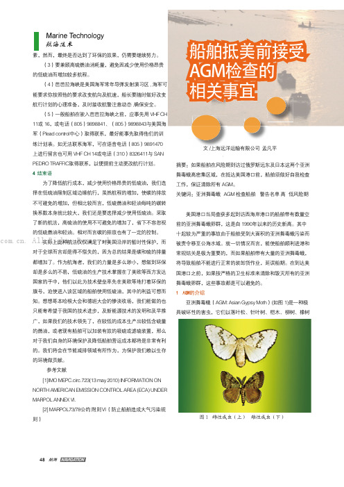
48素,然而,最终是否达到了环保的效果,仍需要继续努力。
(3)要兼顾高硫燃油消耗量,避免因减少使用价格昂贵的低硫油而增加较多航程。
(4)芭芭拉海峡是美国海军常年导弹发射演习区, 海军可能要求你按照他的要求改变航向及航速,船长要随时做好改变航行计划的心理准备,及时接收航警注意动态,确保安全。
(5)一般船舶在驶入芭芭拉海峡之前,应事先用VHF CH 11或16,或电话(805)9898841、(805)9898843与美国海军(Plead control中心)取得联系,最好能事先取得他们的训练计划表。
如无法联系海军,可在语音电话(805)9891470上进行留言也可用VHF CH 14或电话(310)8326411与SAN PEDRO TRAFFIC取得联系,以便提前主动更改航行计划。
4 结束语为了降低航行成本,减少使用价格昂贵的低硫油,我们选择在低硫油限制区域边缘航行,虽然航程的增加,使碳的排放不可避免的增加,但相比较而言,低硫燃油和轻油每吨的碳转换系数本身就比较大,我们还是要选择减少使用低硫油。
采取了新的航法,高硫油的使用不可避免的增加了,省下不容忽视的低硫燃油和轻油。
相对而言碳的排放也有了一定的控制。
实际上此种航法仅仅满足了对美国沿岸的暂时性保护,而对于全球而言却是得不偿失的,因为总的结果是碳和硫的排量都增加了。
作为航海者,我们的力量是多么渺小,想做到环保却是多么的不易,低硫油的生产技术掌握在了美欧等西方发达国家的手中,他们以此为技术壁垒率先在美欧等地打着环保的旗号,迫使进入该区域的船舶使用低硫油,其中的利益可想而知。
想想哥本哈根大会和德班大会的惨淡收场,我们能做的也只能寄希望于我国的技术进步,及新能源技术的发明和及早推广,如果我们的技术领先了,在较低的成本生产出较低含硫量的燃油,或者现有船舶可以加装有效的吸硫或滤硫装置,那么对于我们自身的环境保护及降低船舶营运成本都将是非常有利的。
我们将会在节能减排领域有所作为,为保护我们赖以生存的环境做贡献。
国外GDP32、V8、GSM07物探电磁法仪功能指标比较

国外GDP-32Ⅱ、V8、GMS-07多功能电法仪主要功能指标介绍寇伟在诸多勘探地球物理方法中电磁法当属是一种应用领域广泛、分支众多的重要的物探方法。
在我国最先应用电磁法的领域金属矿产勘探,随着经济的不断发展,电磁法的应用领域已经拓展到地下水勘探、工程勘探、海洋资源勘探等众多领域。
电磁法种类繁多,按其勘探方式可分为电磁测深法和电磁剖面法,而电磁测深法又包括时间域方法和频率域方法。
而应用最广泛,发展最快的是频率域电磁测深法。
电磁法发展历史:1、20世纪50年代,法国的Cagniard和前苏联的Tikhonov提出了大地电磁法(MT);2、20世纪60年代的Berdichevski等(1969),提出了音频大地电磁法(AMT);3、1971年和1978年,Goldstein和Strangberg提出了可控源音频大地电磁法(CSAMT)。
从原理上来讲,大地电磁(MT)和可控源音频大地电磁(AMT)测深的实质测量由于太阳风或太阳黑子活动及赤道区的闪电雷击在地球表面产生的各种频率的水平电场和水平磁场,然后通过阻抗与电阻率的关系计算视电阻率从而了解地下电性结构。
大地电磁法的优点是采用天然场源,不受高阻屏蔽的影响,设备轻便,勘探深度能达到数百公里;其缺点是场源不可控制并且信号微弱,易受自然环境的影响,尤其是在矿山、城区附近很难开展工作,随着电子技术的不断发展和软件处理技术的不断提高,这些问题已经基本得以解决。
可控源音频大地电磁(CSAMT)测深,通过人工发射电磁波解决了场源微弱和多变性问题,增强了信噪比,但同时也引入了场源的影响,电磁场不满足无源区齐次方程,且带有庞大电源的发射机,明显增加了野外工作的难度。
国际市场上的电磁测深仪器有很多,在此仅介绍三种目前技术较为先进、具有综合探测功能的电磁法仪:美国ZONGE公司的GDP-32Ⅱ多功能电法仪,加拿大凤凰公司(phoenix)的V-8电磁系统,德国Metronix公司的GMS-07(ADU-07)综合电磁法仪。
esd stm12.1-1997

ESD STM12.1-1997是一个关于静电放电(ESD)的标准,主要关注的是静电敏感设备的接地要求。
这个标准规定了接地系统的设计、安装和维护要求,以确保静电敏感设备在制造、运输和使用过程中的安全。
具体来说,该标准规定了以下方面的要求:
1.接地系统的设计要求,包括接地电阻、电流容量等。
2.接地系统的安装要求,包括接地线的材料、规格、连接方式等。
3.接地系统的维护要求,包括定期检查、测试和记录等。
这个标准适用于所有静电敏感设备的接地系统,包括电子设备、电子元件、电路板等。
因此,它对于电子产品制造、运输和使用的安全性至关重要。
美军最具杀伤力的武器
美军最具杀伤力的武器美军最具杀伤力的武器时间:2011-05-02 16:16:58 点击:1188次 [ 大中小 ]美国中文网张衡君编译:美国一直研发致命武器,用于伊拉克战场,阿富汗战争上,追击亚盖特基地恐佈组织,例如:MQ9 捕食者侦察机,镭射复仇者,马尔斯机器人等,使美国军队在任何战场上,处于优势,战无不胜,其中有一些武器已经存在了数年,有一些正在改装中,有一些武器仍然在生产。
美国的十大最强武器有哪些?MQ9 捕食者侦察机制造商:通用原子航空系统公司发布日期:2001年MQ9 捕食者侦察机,是一种无人机,是美军目前一种重要的远程中高度监视侦察系统。
目前该机已增加了使用精确制导武器攻击地面或空中目标的能力,并已经发展出了具备一定隐身能力的C型,研发已经有超过 10年,直至最近,主要用于情报和侦察,具有长时程、高海拔监视的设计。
MQ9 捕食者侦察机,翼展长达84英尺,起飞重量为7000磅,续航时间 36小时。
无人机爬升到52,000英尺上空,可读取来自两英里远的车牌,能够携带 500磅炸弹。
在伊拉克战争中,“捕食者”曾与米格-25交战,使得该机成为了第一种直接进行空空战斗的无人机。
“捕食者”装有雷达、电视摄影机和前视红外装置,其获得的各种侦察影像,可以通过卫星通信系统可实时的向前线指挥官或后方指挥部门传送。
截至2011年3月,空军培训更多人员来控制无人机,比任何其他武器的发展蓬勃。
AA12 艾奇逊(Atchisson)突击霰弹枪制造商:麦斯韦尔(Maxwell Atchisson)发布日期:2005年艾奇逊AA-12自动霰弹枪特别适合特种部队、守备部队、巡逻部队、反恐怖部队等,由于霰弹枪的射程在100米左右,减少了因跳弹或贯穿前一目标后,伤及后面目标的概率。
所以霰弹枪特别适用于丛林战、山区战、城市战及保护机场、海港等重要基地和特殊设施。
此外,专门用于突发战斗,由于霰弹枪具有在近距离上火力猛、反应迅速,以及面杀伤的能力,故在夜战、遭遇战及伏击、反伏击等战斗中能大显身手。
AN-777

LM2577Three Output, Isolated Flyback RegulatorMany voltage regulator applications require multiple outputs, such as a computer’s power supply or a regulator used to meet the voltage requirements inside an automobile.Some of these applications require isolation between the regula-tor’s input and output for protection and separate ground ing this criteria,a LM2577simple switcher flyback regulator has been designed with multiple(3)outputs and input-to-output isolation.The three outputs are:1)5V@ 150mA,2)7.5V@100mA,and3)−7.5V@70mA.The table below gives the electrical specifications.The LM2577flyback regulator uses a4N27optocoupler to provide a galvanic isolation.The base resistor of the opto-coupler is chosen so that it is large enough(47kΩ)to supply a minimum base current—which in turn,demands a lower drive current to the optocoupler’s diode—but not so large as to produce a pole in the regulator’s frequency response.If the pole’s frequency is below the regulator loop’s crossover frequency,stability problems will occur.Thus,a zero must be developed,requiring extra circuitry,to compensate for the extra pole in the loop.An LM385Adjustable Voltage Reference,along with resis-tors R O1and R O2,set the main output voltage to5V±4%by the equation:V O=1.24V(1+R O2/R O1).The LM385sup-plies a drive current to the optocoupler(about10mA)pro-portional to the output voltage.Due to the high gain of the LM385,the LM2577’s error amplifier is bypassed,and the feedback signal is fed directly to the compensation pin.Em-ploying the error amplifier’s gain block in the loop would add with the LM385gain(the optocoupler’s gain is around unity) to produce a very large overall loop gain.Such a large loop gain makes the loop too difficult to stabilize—thus the by-passed error amplifier.With the regulator input voltage of 26V and full load on all outputs,the frequency response has a crossover frequency at1kHz and phase margin of90˚. The flyback regulator’s mode of operation is continuous,so a large primary inductance(L P=300µH)is needed for the ing a Ferroxcube812E250-3C8E core,the primary winding requires about50turns.With the turnsratios as they are shown on the schematic and the small core size, the transformer windings must be wound tightly so that they fit the core windows.Interlaying the primary winding be-tween the secondary windings improves the transformers coupling.The zener diode circuit(V Z,R Z,R I)is added to provide the optocoupler transistor with about20µA of bias current,on top of the current sourced from the compensation pin(about 7µA).The isolation resistor,between the compensation pin and the zener diode,needs to be as large as100kΩ,or at start-up,the compensation pin will see too large a voltage, turning the power switch fully on—thus forcing the LM2577 into current limit.Also,to ensure good line regulation,the dy-namic impedance of the zener diode must be very good. Test data for this regulator follows the schematic.Since feed-back is taken from Output1,its load and line regulation are better than that of the other two outputs,which rely on feed-back through the transformer coupling.The output ripple voltage of all three outputs is largely dependent on the filter capacitors used,and could be reduced by the use of addi-tional high-quality filter capacitors or an additional L-C filtersection.ELECTRICAL TEST DATA V I =16V–36VOutput Line Regulation Load RegulationOutput Ripple VoltageVoltages (I O =Full Load)(V I =26V)(T A =25˚C)V O1=5V 0.2%0.04%50mV30mA–150mAV O2=7.5V0.3%3%50mV20mA–100mAV O3=7.5V0.3%2%50mV 12mA–70mALM2577Three Output,Isolated Flyback RegulatorAN011217-2Load Transient Response A.Load Current,50mA/divB.Output Voltage Change 50mV/div (AC-Coupled)Horizontal:5ms/divAN011217-3Output Ripple Voltage 20mV/div (AC-Coupled)Horizontal:5ms/div 23LIFE SUPPORT POLICYNATIONAL’S PRODUCTS ARE NOT AUTHORIZED FOR USE AS CRITICAL COMPONENTS IN LIFE SUPPORT DEVICES OR SYSTEMS WITHOUT THE EXPRESS WRITTEN APPROVAL OF THE PRESIDENT OF NATIONAL SEMICONDUCTOR CORPORATION.As used herein:1.Life support devices or systems are devices orsystems which,(a)are intended for surgical implantinto the body,or (b)support or sustain life,andwhose failure to perform when properly used inaccordance with instructions for use provided in thelabeling,can be reasonably expected to result in a significant injury to the user.2.A critical component in any component of a life support device or system whose failure to perform can be reasonably expected to cause the failure of the life support device or system,or to affect its safety or effectiveness.National Semiconductor Corporation AmericasTel:1-800-272-9959Fax:1-800-737-7018Email:support@National Semiconductor EuropeFax:+49(0)180-5308586Email:europe.support@Deutsch Tel:+49(0)180-5308585English Tel:+49(0)180-5327832Français Tel:+49(0)180-5329358Italiano Tel:+49(0)180-5341680National Semiconductor Asia Pacific Customer Response Group Tel:65-2544466Fax:65-2504466Email:sea.support@National Semiconductor Japan Ltd.Tel:81-3-5620-6175Fax:81-3-5620-6179A N -777L M 2577T h r e e O u t p u t ,I s o l a t e d F l y b a c k R e g u l a t o rNational does not assume any responsibility for use of any circuitry described,no circuit patent licenses are implied and National reserves the right at any time without notice to change said circuitry and specifications.。
常用中图分类号
常用中图分类法简表目录O数理科学和化学 (1)O4物理学O41理论物理学O42声学O43光学O44电磁学、电动力学O45无线电物理学O46真空电子学(电子物理学)O469凝聚态物理学O47半导体物理学O6化学 (2)O61无机化学O62有机化学O63高分子化学(高聚物)O64物理化学(理论化学)、化学物理学O65分析化学O69应用化学O7晶体学 (3)P天文学、地球科学 (4)P1天文学P2测绘学P3地球物理学P35空间物理P4大气科学(气象学)Q生物科学 (6)Q6生物物理学Q94植物学Q95动物学R医药、卫生 (6)R3基础医学R4临床医学R5内科学R6外科学R77眼科学R8特种医学T工业技术 (7)TB一般工业技术 (7)TB3工程材料学TB4工业通用技术与设备TB5声学工程TB7真空技术TB8摄影技术TB96光学计量TG金属学与金属工艺 (8)TH7仪器、仪表 (9)TH74光学仪器TH75天文仪器TH76地球科学仪器TH761测绘仪器TH762地球物理观测仪器TJ武器工业 (11)TL原子能技术 (11)TM电工技术TN无线电电子学、电信技术 (12)TN0一般性问题TN1真空电子技术TN2光电子技术、激光技术 (12)TN21红外技术及仪器TN23紫外技术及仪器TN24激光技术、微波激射技术TN248激光器 (12)TN248.4半导体激光器 (13)TN25波导与集成光学 (13)TN3半导体技术 (13)TN384发光器件 (13)TN4微电子技学、集成电路(IC) (13)TN6电子元件、组件 (13)TN7基本电子电路TN8无线电设备、电信设备 (13)TN91通信 (14)TN92无线通信TN94电视TN95雷达TN96无线电导航TN97电子对抗(干扰及抗干扰)[TN98] 无线电、电信测量技术及仪器TN99无线电电子学的应用TP自动化技术、计算机技术 (16)TP2自动化技术及设备TP3计算技术、计算机技术TP7遥感技术TQ化学工业 (18)V航空、航天V1航空、航天技术的研究与探索V2航空V4航天(宇宙航行)[V7] 航空、航天医学O数理科学和化学O4 物理学O41理论物理学O413量子论O413.1量子力学(波动力学、矩阵力学)O42声学O426.3 声光作用O43 光学(光仪器制造入TH74,显微镜学入TH742,发光学入O482.31,激光入TH24,光电子学入TN201)O431 光本性的理论(光子入O572,中子光学入O571.56)O431.1 光的电磁理论O431.2 量子光学(光的量子理论及波粒二象性入此)O432 光辐射、光度学、色度学O432.1 光辐射O432.1+1 气体放电辐射O432.1+2 受激光发射O432.2 光度学(测光学)O432.3 色度学O433 光谱学O433.1 光谱测量O433.2 光谱激发O433.3 谱线结构O433.4 光谱分析O433.5 各类光谱O433.5+1 吸收光谱O433.5+2 火焰光谱O433.5+3 弧光谱O433.5+4 激光光谱O433.5+5 火花光谱O433.5+9 其他光谱O434 X射线、紫外线、红外线O434.1 X射线(α、β、γ射线入O571.32)O434.13 光谱O434.14 与物质的相互作用O434.19 应用O434.2 紫外线O434.3 红外线O435 几何光学(高斯光学、近轴光学入此)O435.1 反射与折射(梯度折射率光学入此)O435.2 光具组理论与象差理论(参见TH74)O436 物理光学(波动光学)(分子光学入此,光子入O572.31,中子光学入O571.56,量子光学入O431.1,光的电磁理论入O431.1,薄膜光学入O484.4+1,晶体光学入O734,集成光学、纤维光学入TN25)O436.1 干涉与衍射O436.2 吸收与散射O436.3 偏振与色散O436.4 电光现象(克尔效应)与磁光现象(法拉弟效应)O437 非线性光学(强光与物质的作用)(非线性光谱学入此)O437.1 合频效应O437.2 受激布里渊散射O437.3 受激拉曼散射O437.4 光参量器件O437.5 光自聚焦O438 信息光学O438.1 全息光学O438.2 傅里叶光学O439 应用光学(在各方面的应用入有关各类)O44 电磁学、电动力学O461.2 各类型放电O461.2+1 辉光放电O461.2+2 弧光放电O462 阴极电子学O462.1 热电子发射、热阴极O462.2 二次电子发射、二次电子发射阴极 O462.3 光致发射、光阴极、外光电效应 O462.4 场致发射、场致发射阴极O462.5 离子发射、离子发射阴极O463 带电粒子光学O463+.1 电子光学O463+.2 离子光学O469 凝聚态物理学O47 半导体物理学O471 半导体理论O471.1 半导体量子理论O471.3 极化与激子理论O471.4 半导体晶体物理O471.5 半导体能带结构O472 半导体性质O472+.3 光学性质O472+.8 光电效应O474 杂质和缺陷O475 P-N结O48 固体物理学(晶体物理学入O73)O481 固体理论O481.1 能带论[O481.2] 点阵力学O481.3 多体理论O481.4 穆斯堡尔效应O482 固体性质O482.1 力学性质与声学性质O482.2 热学性质O482.2+1 热容量O482.2+2 导热性O482.2+3 热膨胀O482.3 光学性质O482.31 发光学O482.5 磁学性质O482.55 磁光效应O482.7 光电效应O483 固体缺陷O484 薄膜物理学O484.1 薄膜的生长、结构和外延 O484.2 薄膜中的力学效应O484.3 薄膜中的输运现象O484.4 薄膜的性质O484.4+1 光学性质O484.5 薄膜测量与分析O51 低温物理学O52 高压与高温物理学O53 等离子体物理学O531 产生O532 约束与加热O532+.25 激光加热O532+.26 高能粒子注入加热 O536 辐射与测量O539 等离子体物理的应用O55 热学与物质分子运动论O551 热学O552 物质分子运动论O552.4+23 光学性质O552.4+24 电磁效应O56 分子物理学、原子物理学O561 分子物理学O561.3 分子光谱 O561.5 碰撞与散射O562 原子物理学O562.3 原子光谱学O562.3+1 谱线结构O562.3+2 光谱线在电场及磁场中的分裂O57 原子核物理学、高能物理学O571.32 各种射线及其衰变O571.32+1 α射线及α衰变O571.32+2 β射线及β衰变O571.32+3 γ射线及γ衰变O571.33 射线与物质的相互作用O571.42+4 电子和光子引起的核反应O572.3 粒子类型O572.31 光子与规范粒子交子、引力子入此。
美国导弹鉴赏
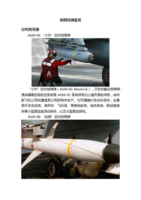
美国导弹鉴赏空对地导弹AGM-65 “小牛”空对地导弹“小牛”空对地导弹(AGM-65 Maverick),又称幼畜空地导弹,是由美国空军航空系统局AGM-65系统项目办公室负责的项目,由休斯飞机公司和雷锡恩公司研制并生产。
它可精确打击点状目标,主要用于攻击坦克、装甲车、飞机场、导弹发射场、炮兵阵地、野战指挥所等小型固定或活动目标,以及大型固定目标。
AGM-88 “哈姆”空对地导弹AGM-88反辐射导弹(英文:AGM-88 HARM Anti-Radiation Missile [1] ),是20世纪70年代美国研制的一型机载高速反辐射导弹。
该导弹由美国得克萨斯仪表公司为美国海、空军研制生产的空对地反辐射导弹,绰号“哈姆”(HARM),主要用于压制、摧毁地面和舰上防空导弹系统的雷达和高炮控制雷达。
AGM-114 “地狱火”空对地反坦克导弹AGM-114反坦克导弹,是一种能从海、陆、空中发射的、攻击海上或陆地上带有装甲机动目标的导弹,有多种改进型号在役,具有发射距离远,精度高,威力大等优势,采用激光制导,抗干扰能力强,不需目标照射保障。
AGM-142 “突眼”空对地导弹“突眼”AGM-142空地导弹是以色列空军装备使用的防区外通用战术空地导弹,用以攻击严密设防的坚固目标,研制始于80年代初,为满足以色列空军关于提供一种防区外攻击坚固设防目标的电视制导空地导弹的要求,采用独特的正常式气动外形布局。
AGM-154 联合防区外空对地导弹AGM-154式联合远程武器亦称“杰索伍”。
美国于1992年开始研制,1995 年进行试验,现已装备部队并在“沙漠之狐”行动中首次投入使用,是一种新型防区外打击武器。
1999年1月24日,美海军一架F/A-18战斗机在伊拉克“禁飞区”发射了该型弹中的A型弹,攻击了伊军一个防空设施,首次投入实战获得成功。
科索沃战争中该型弹也投入了使用,效果不详。
AGM-158 联合防区外空对地导弹AGM-158联合防区外空地导弹是美国空军装备的新型空射巡航导弹,主要用于精确打击敌严密设防的指挥与控制系统、通信系统、防空系统、弹道导弹发射架以及舰船等高价值目标。
各国飞机的奶妈(空中加油机)一览
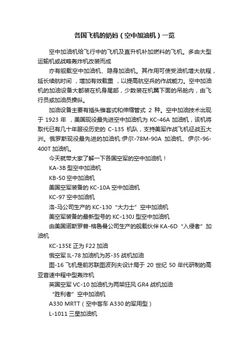
各国飞机的奶妈(空中加油机)一览空中加油机给飞行中的飞机及直升机补加燃料的飞机。
多由大型运输机或战略轰炸机改装而成亦有舰载空中加油机、隐身加油机。
其作用可使受油机增大航程,延长续航时间,增加有效载重,以提高航空兵的作战能力。
空中加油机的加油设备大都装在机身尾部,少数装在机翼下面的吊舱内,由飞行员或加油员操纵。
加油设备主要有插头锥套式和伸缩管式2种。
空中加油技术出现于1923年,美国现役最先进空中加油机为KC-46A加油机,该机将取代已有几十年服役历史的C-135机队,支持美军作战飞机征战五大洲。
俄罗斯现役最先进的加油机:伊尔-78M-90A加油机、伊尔-96-400T加油机。
今天就带大家了解一下各国空军的空中加油机!KA-3B型空中加油机KB-50空中加油机美国空军装备的KC-10A空中加油机KC-97空中加油机洛-马公司生产的KC-130“大力士”空中加油机美空军装备的最新型号的KC-130J型空中加油机由美国诺斯罗普-格鲁曼公司生产的舰载伙伴KA-6D“入侵者”加油机KC-135E正为F22加油俄空军IL-78加油机为苏-35战机加油图-16飞机是前苏联图波列夫设计局于20世纪50年代研制的高亚音速中程中型轰炸机英国空军VC-10加油机为两架狂风GR4战机加油“胜利者”空中加油机A330 MRTT(空中客车A330的军用型)L-1011三星加油机印度空军的伊尔-78MKI为幻影战机进行空中加油德国空军A310 MRTT(空中客车A310的军用型)KC-767A型空中加油机中国空军HY-6(轰油6)为歼8加油免责声明:图文信息来源于网络,版权归原作者,平台发布只限于服务飞行爱好者,若有来源标注错误或侵犯了您的合法权益,请作者持权属证明与本网联系,我们将及时更正、删除,谢谢。
(旋翼机、固定翼、直升机相关图纸、资料)文章源 | 网络。
Ions Measurement at the Edge of HT-7 Tokamak
Ions Measurement at the Edge of HT-7 Tokamak 凌必利;王恩耀;高伟;万宝年;李建刚
【期刊名称】《等离子体科学和技术(英文版)》
【年(卷),期】2005(7)2
【摘要】需要一种可靠的测量托卡马克等离子体中离子和离子温度的方法,为此已在HT-7托卡马克上开发了一种类似欧米茄的仪器。
本文显示了类似欧米茄的仪器的基本布局。
上次关于HT-7托卡马克的实验活动中已进行了工作气体离子的测量。
研究了离子电流,电子推斥极电压和阱电压之间的关系。
这种类似欧米茄的仪器还提供了边缘等离子体离子温度。
【总页数】3页(P2716-2718)
【关键词】离子测量欧米茄托卡马克
【作者】凌必利;王恩耀;高伟;万宝年;李建刚
【作者单位】Institute of Plasma Physics the Chinese Academy of Sciences,Hefei 230031,China;Southwestern Institute of Physics Chengdu 610041,China
【正文语种】中文
【中图分类】TL631.24;O532.21
因版权原因,仅展示原文概要,查看原文内容请购买。
英国陆军直升机的电子战设备选择

英国陆军直升机的电子战设备选择
佚名
【期刊名称】《电子信息对抗技术》
【年(卷),期】1992(000)005
【摘要】可以预料,即将来临的就英国陆军空军的125架下一代战场攻击直升机展开的竞争,将突出高水平的电子战保护。
马可尼防御系统公司已提出了一种综合的防御系统,以供“眼镜蛇”直升机使用。
【总页数】1页(P7)
【正文语种】中文
【中图分类】TN97
【相关文献】
1.美陆军直升机将安装先进的电子战自卫系统 [J], 雨相
2.陆军的重要战术装备电子战直升机的发展 [J],
3.美国陆军开展新的电子战项目整合信号情报、电子战和网络空间能力 [J],
4.美陆军直升机电子战自卫系统动态 [J], 立平
5.阿·韦公司获英国陆军WAH-64直升机IOS项目 [J], 陈
因版权原因,仅展示原文概要,查看原文内容请购买。
