螺杆空压机使用说明书(英语版)
30hx-12开利螺杆机手册英文版

Front . . . . . . . . . . . . . . . . . . . . . . . . . . . . . . . . . . .3 ft (914 mm) Rear. . . . . . . . . . . . . . . . . . . . . . . . . . . . . . . . . . . . .3 ft (914 mm) Top . . . . . . . . . . . . . . . . . . . . . . . . . . . . . . . . . . . . .2 ft (610 mm) Ends . . . . . . . . . . . . . . . . . . . . . . tube length at one (either) end;
INSTALLATION
Step 1 — Inspect Shipment — Inspect unit for damage upon arrival. If damage is found, immediately file a claim with the shipping company. Verify proper unit delivery by checking unit nameplate data (see Fig. 1). Do not store units in an area exposed to weather because of sensitive control mechanisms and electronic devices.
SAFETY CONSIDERATIONS
Installing, starting up, and servicing this equipment can be hazardous due to system pressures, electrical components, and equipment location. Only trained, qualified installers and service mechanics should install, start up, and service this equipment.
英格索兰螺杆空压机使用说明书
99285165 A
欢迎您使用上海英格索兰压缩机有限公司 生产的各种牌号的螺杆压缩机
SIRC 有权对产品进行修改和改进,不负有对已出厂产品进行相应修改和改进 的义务。
用户订单号:________________ I-R 公司订单号:________________ 为了便于查询,请将你所购的机器编号和型号记录在此
1.原主机返回时是装配就绪的且未打开过的。 2.提交一直使用着英格索兰公司的机油、过滤器和油分离器芯的证明文件。至 于所要求的正确的机油、过滤器和油分离器芯的图号请参考操作零件手册。 3.提交一直遵照推荐间隔周期进行维护保养的证明文件。
注意:详细内容须与英格索兰公司售后服务部门具体联系商谈。
保修期 标准 可选
3
a) 不可能受到英格索兰公司认可, b) 可能削弱使用者及其他人的安全,并 c) 可能侵害英格索兰公司的一切要求。 表1 以本机组来制造压缩空气,用于: a)直接的人身消耗 b)未通过可靠过滤和纯度检验的间接的人身消耗。 在本手册“概述”章节中指定的环境温度范围外使用本机组。 冒任何实际的或可预见的危险,在可燃性气体或蒸汽达危险程度的地方使用本 机组。 使用装有未经英格索兰公司认可的零部件/润滑油/液体的机组。 使用安全部件或控制部件已失缺或失效的机组。 对以上内容的确切含义,请索取原始英语版本。本公司不承担此手册翻译中发 生的与英语版本间的偏差。 版权 2000 英格索兰公司
扩充范围
5 年/10000 小时 有限保修 (参阅操作手册)
零件 英格索兰
月
小时
覆盖范围
6
无限制
仅限零件
主机更换 主机
月பைடு நூலகம்
小时
扩充范围
美国寿力双螺杆空压机使用说明书
欢迎阁下购买并使用 寿力亚洲公司 生产的固定式螺杆压缩机
希望寿力亚洲公司生产的各种规格的固定式螺杆压缩机在您的工作中 发挥预期的作用。
在您和您的工作人员操作和维护寿力亚洲公司的保留对产品不断研究和改进的权利,不负有对以前出厂 的产品进行修改和改进的义务。
VI
7.8 7.9 7.10 7.11 7.12
零件更换和调整· ………………………………………………………………………………… 32 故障分析与排除—仪表型· ……………………………………………………………………… 37 故障分析与排除—电脑型· ……………………………………………………………………… 39 传感器使用说明及监控器参数的校准· ………………………………………………………… 41 管路安装图· ……………………………………………………………………………………… 41
第八章
8.1 8.2
电气原理图
仪表型控制电气原理图· ………………………………………………………………………… 44 电脑板控制电气原理图· ………………………………………………………………………… 45
第九章
常用备件· …………………………………………………………………………………… 46
VII
LS12-50&LS16-60/75LF 系列螺杆压缩机操作手册
第四章
4.1 4.2 4.3 4.4
压缩机的安装
机组的安装· ……………………………………………………………………………………… 16 通风和冷却· ……………………………………………………………………………………… 17 供气管路的安装· ………………………………………………………………………………… 18 联轴器检查· ……………………………………………………………………………………… 18
螺杆空压机使用说明书
目录第一章前言 (2)第二章安全规程 (3)一.安装预防措施 (3)二.操作预防措施 (3)三.保养预防措施…………………………………………………四.失火时的预防措施……………………………………………第三章空压机机组简介………………………………………………一.主要技术规格..................................................................................................................二.概述............................................................第四章...空压机机组的安装.......................................一.......安装场所的选择..................................二...............安装基础..........................................三...................安装管道.....................................四........................供电状况.................................第五章........................系统流程及各部件功能....................................统..........................................一....系气路................................................二.............油路系统..........................................三................冷却系统............安全保护...............四................控电气制、调节系统及..................章第六..................操作...............................................................初次启动前的准备工作................一..................停开车与车............................二..............................运行中的注意事项..........三.................................作.........................四.................................基本操........................七第章........................整保养及调................................................养保周期........................一............................定选择润滑油及期更换....二...........................保长期停机养...............三..................................保滤清器的更换及养.四..........................................气空.........五..................................的冷却器保养.................................整装安全保护置的调与检查..........六...............及故障修理........................章八第......................................................修及.一故生能机空压可发的障维...............电气.......二......维及障的生发可统系能故修 (1)第一章前言尊敬的用户,非常感谢您选用神龙牌螺杆式空气压缩机,SLOG系列产品是依据最新技术标准设计制造,具有操作简单、运行稳定可靠、效率高、维护方便等优点和特性。
水冷螺杆冷水机组使用说明书英文版本资料
Installation & Operation manualScrew Type Water Cooled Chiller Nanjing Lidesheng Machinery CO.,LTD.ContentPart 1 Installation and maintenance Introduction (2)Schematic drawing for service clearance (3)Schematic drawing for hoisting (4)Setup and maintenance (5)Part 2 Controlling and handling Introduction (12)Part 1 Installation and maintenanceIntroductionMENERGY MSSH serial Water-cooled Screw-type Chiller, which is concisely designed, applies the advanced semi-enclosed dual-screw compressor and the high-effective heat exchange tube with the most updated technologies, and can be controlled through the advanced microcomputer. This product has advantages of stable system, low oscillation, high reliability and high effectiveness on energy saving. MENERGY original anti-reversal program for the compressor can strengthen the running reliability of the chiller. This product has more than twenty types for being extensively applied in many comfortable or technical situations by the customer.Before the chiller is started up, all the related personnel in charge of setup, startup, operation and maintenance should carefully read through this manual so as to know all the precautions onsite.Schematic drawing for service clearanceSchematic drawing for hoisting Single-head:Dual-head:Setup and maintenanceSetup and maintenance of the chiller should only be carried out by a qualified person who has been trained professionally, and is familiar with local standards and rules and has practical operational experience. The trial running of the chiller must be carried out by the professional service supplier to ensure the quality of the chiller.Check before acceptanceAfter the device has arrived, check if all the items listed in the delivery order are complete, and any part damaged during transportation should be informed to the forwarding agent with written form for claim. Before setup, check if the local supply voltage, frequency and so on are complying with the chiller. MENERGY will bear no liability for any damage after the device has been accepted.HoistingHeavy-duty ropes or chains should be used for hoisting through the hoisting holes of the chiller, and the control cabinet and other parts of the chiller should be protected from damage when hoisting (The schematic drawing for hoisting introduced above should be referred to).Environmental requirementThe chiller is suitable to be used in the environment that the surrounding temperature is -15℃ above and the relative humidity is ≤ 95%, and the ground for placement should be horizontal and with enough solidity or reinforcement measures should be taken (The requirements in the schematic drawings of ground base and service clearance for the chiller should be referred to).Water quality requirementAs the composition of local water is complicated, the water quality should be check when some uncommon water (such as industrial waste water, ground water, etc.) is used. If the water quality does not satisfy the requirement for the water used in air-conditioning, the water should be treated according to the Specification for Design of Industrial Re-circulating Cooling Water Treatment or other related standards.Water pipesBoth outlet and inlet of the chiller should be equipped with a stop valve, a thermometer and a pressure gauge for routine check and maintenance of the water system; and both outlet and inlet of the water pump should be equipped with a strainer to prevent impurities from going into the pump or the vessel; before insulating the heat of the water pipe, the sealing of the pipeline should be checked when the water is to go into the chiller; all the pipelines connected with the chiller should be equipped with vibration dampers and flow controllers (such as water flow valves, water pressure difference switch, etc.) as per the requirement; when a device for contamination draining is to be mounted to the water system of the air-conditioning engineering, it should be avoided from the pipelines of the outlet and inlet of the chiller, or the normal operation of the chiller would be disturbed. Schematic drawing for the external water pipeline systemInlet Of The Colling TowerInlet Of The Terminal InstallationOutlet Of The Colling TowerOutlet Of Terminal InstallationPipeline design Installation Notesa)Pipe works must avoid any unnecessary bends and offset(up and down).b)Install gate valve for every joint for service and maintenance.c)Air vent must be installed at the highest position.Open the air vent to realease theair trapped in the water system.d)Water pump must install at water return linee)At the lowest point of the pipe work,install a gate valve drain out water.f)At the highest point of the pipe work,install a manual or automatic air vent.g)Install strainer before water entering to the water pump.h)Flush lot of clean water to remove foreign material before unit start up.i)Pressure gauge and thermometer must be installed at visible and accessiblelocation.Check before starting upWater circuit partCheck all the pipelines of the water system to ensure that the evaporator and the condenser are correctly connected and the water flow direction is correct. Check if the inlet pipe and the outlet pipe of the heat exchanger mentioned above are well connected, and then open all the water valves and start up the corresponded water pump to wash the pipes so as to ensure the water system is clean and check if there is any leakage at the pipes and joints. Discharge the air in the water circuit of the evaporator and the condenser, and the water circuit should be keep clean away from rust. Check the resistance loss at the water side of the evaporator and the condenser against the water volume. Check if the temperature transducers are correctly connected.Electric circuit partCut off the main isolating switch and then check all the startup circuits and control circuits of the control cabinet to ensure all the switches are in off position. Check the power supply to the chiller and the voltage fluctuation range should be within ±10% of the rated voltage shown on the nameplate of the compressor, and the unbalance of the phase voltage should be within 2%. Check if there is enough power supply capacity to ensure the startup and full load running of the chiller. Check if all the electric wires and fuses have the matched specification with the running of the chiller, and finish all the interlock control circuits according to the related electric control drawing. Check and ensure all the ancillary equipments and control equipments for air-conditioning are in normal operation and have enough refrigerating capacity to satisfy the running requirement of the chiller at the first operation.Chiller partMake sure that the engine oil heater of the compressor has been electrified for 24 hours, and examine the oil level through the inspecting mirror of the oil separator, and refill oil if the oil level can not be seen. Fully open the manual stop valve on the sparging pipe and remove the seal bonnet away, and fully open the suction and discharge stop valve and then counterclockwise turn it back for 1/2 circle, and then fully open the liquid supply stop valve and start up the ancillary equipments, the condensed water pump and the refrigerated water pump, and finally check if all the safety control equipments are in original status and if the settings are correct. See <Table 1> below for the related items for checking.Safety equipmentsThe chiller is equipped with safety protective devices to ensure safe running, and if one of the safety protective devices is in operation, an error indicator will turn on, and the corresponded function will stop while the other functions will be still normal. It isrecommended to stop the chiller for troubleshooting to avoid from more serious accident only if any part becomes abnormal. See <Table 2> for the detailed series of the safety protective devices of the chiller.Recommended running rangeRecommended maintenance periodsTroubleshooting for the Screw-type ChillerPart 2 Controlling and handlingAs the leaving water temperature is setting, the operator press start key then the unit will be operating automatically; and it will stop when press stop key. The intervention from operator is not needed during entire process.Rotating test and manual test can be utilized in order to facilitate regulation and repairing.◆Data SupervisionWhen the unit is power on, the unit will check digital and analog input automatically and the unit will adjust the capacity based on the water temperature in time. The data collecting is very fast and its accuracy is high, it will reflect the actual fact.◆TroubleshootingTrouble will be solved immediately via the program and it will make pre-alarm or alarm at the same time. The unit will stop running when the unit occur severe trouble in order to avoid further damage.Safe and Easy to ManageThe protection of setting password is used in order to protect safety and performance of the unit. You can give different authority according to your different requirement, so that you will not be worried about the abnormal damage of unit as the operator or other person exceed their authority. In other words, the unit is safety and easy to manage.。
螺杆空压机控制器(面板)操作说明

螺杆空压机控制器 操作说明V1.3上海宏赛自动化电气有限公司2007-10-12一、基本操作面板二、按键介绍启动 ―― 在无故障情况下启动运行空压机并可从停机切换到运行状态。
停止 ―― 停止运行空压机。
设定键 ―― 修改参数后,按此键确认数据存储输入。
上移键 ―― 在缺省页面下作为时间查询键;数据修改时,按此键增加该数位;在菜单选择时作为选择键。
下移键 ―― 在缺省页面下作为主菜单键;数据修改时,按此键减少该数位;在菜单选择时作为选择键。
移位/确认键 ―― 在缺省页面下作为近/远控切换键;数据修改时,此键作为移位键;在菜单选择时作为确定键。
返回键 ―― 在菜单操作时,此键作为返回键返回上一级菜单。
三、外部开关量和模拟量的输入输出特点说明经济型空压机控制接口说明JP1引脚号名称 意义 1PIN+ 压力传感器输入+ 2PIN- 压力传感器输入- 3TIN- 温度传感器输入- 4TIN- 温度传感器输入- 5TIN+ 温度传感器输入+ 6I1 主机电流(R)传感器输入 7I2 主机电流(T)传感器输入 8FIR 风机电流(R)传感器输入 9FIT风机电流(T)传感器输入 10VST ST 相电压传感器输入 11GND 信号公共点JP4引脚号名称 意义 1DI0 空滤信号输入(常开) 2DI1 油滤信号输入(常开) 3DI2 油细信号输入(常开) 4DI3 压力开关输入(常开) 5 DI4 紧停信号输入(常闭)6 GND 输入信号公共点7 A RS485通讯口8 B RS485通讯口JP3引脚号 名称 意义1 ACIN0 接触器用电源输入1(内部继电器输出公共点)2 ACIN1 接触器用电源输入2 (内部RC公共点)3 VD 加载电磁阀输出4 KF 风机接触器输出5 RCS Y接插器RC 输出6 KS Y接插器输出7 RCD △接触器RC输出8 KD △接插器输出9 KM 主接触器输出JP5引脚号 名称 意义1 XGD 接大地2 ACIN0 ~25V电源输入(与R相同名)3 ACIN1 ~25V电源输入(与S相同名)四、空压机操作使用介绍控制器通电后,操作面板上电源信号灯亮。
螺杆式空气压缩机控制器操作说明
螺杆式空气压缩机控制器操作说明书Contents Page 1按键说明——————————————————————————22界面说明——————————————————————————33操作说明——————————————————————————74保养部件提示————————————————————————85故障报警和处理———————————————————————9附1基本参数说明表———————————————————————10附2电气原理图—————————————————————————121、按键说明2、界面说明1)开机和主页面检查紧急停止按钮,使其处于打开状态。
控制器通电后,文本显示器液晶背光亮。
控制器上电后,进入欢迎页面:当通讯成功后自动进入主页面:2)查询菜单在主页面下,按‘设置’键,进入菜单选择:键操作)i.系统状态(SYS STAT)菜单在查询菜单下,选择系统状态,进入系统状态查询:符号提示区:2006年日12:00:00按‘↓’键:符号提示区:空车时间:小时ii.维护查询(M.I.PAGE)菜单在查询菜单下,选择维护查询,进入维护参数查询:符号提示区:空滤剩余时间:1234小时按‘↓’键:油滤剩余时间:1234小时按‘↓’键:按‘↓’键:按‘↓’键:注:此页面只有在皮带传动的设备上才能显示;对于齿轮传动的则显示齿轮油使用时间iii.参数设置(PARA SET )菜单参数设置内含“风机测试”及“加载阀测试”功能参数,此两项参数只有在正常停机状态下才会显示,并可进行调试。
运行状态或紧急停机状态下该参数不显示。
油分剩余时间:1234小时润滑油剩余时间:1234小时皮带剩余时间:1234小时3)操作指示i.密码输入说明:12、密码输入错误,页面会提示:‘密码或权限错误!’,然后重新回到密码设置。
密码输入说明:1、按页面所示校验码,输入系统密码。
2、密码分为两级:用户级密码(二级),工厂级密码(一级)。
阿特拉斯螺杆空压机电气说明书

Mark4,Elektronikon11 Operating manual一. 控制屏(图1.1)电脑显示屏/按钮/键代号名称功能1停机按钮按此键停止空气压缩机,显示屏退出.空压机将空载运行大约30秒后停机.2启动按钮按此按键启动空压机.显示屏显示调节器的运行状态.显示屏退出(如果空压机手动调为空载时)3显示器显示出空压机的运转状态,协助需求或故障4翻业按键在显示屏上翻页5横移按键用水平箭头选择显示参数,只有向右的箭头对应的参数才能修改6LED上的电压显示开关开启时的电压7LED总报警当维护器警告或停机警告条件存在时或传感器不受控制时报警灯亮8LED总在传感器的停机功能消失或紧急停机后的情况下报警灯会闪烁. 9功能键控制并执行程序.S3 紧急停机按钮在紧急情况下立即停止空压机,在修复后.将此按钮拔出.10报警符号11自动运行符号12电源指示灯(1.1)二. 功能键使用的功能键:手动调节空压机的负荷调出或设定程序重新设定电动机的过负荷,停机,维护器信息或紧急停机.进入调节器所收集的数据.功能键都根据显示菜单的不同而不同.实际上都缩写并显示有关键的最底部一行,普通的缩写如下:缩写名称功能Add 增加指令用来增加空压机的自动启动/停机(日期) Back 返回指令返回到的选择或菜单Canc 取消当设定参数有误时.用来取消已设定的数dle 删除用来删除空压机的自动启动/停机时间Help 帮助帮助寻找Atlas Copco的内部地址Lim 上下限显示允许设定的上下极限数据Load 负载手动操作空压机负载Main 回到主目录从任一画面回到主目录Menu 菜单从主画面开始可进入子目录Menu 菜单从任一子目录返回到先前的目录Mod 修改修改设定参数Prog 编写输入将新的设定数据编写输入Rset 重新设定重新设定计时器及信息Rtrn 回归回归到前一页或前一目录Unld 空载手动操作空压机空载Xtra 额外的找寻调节器的构造模式三. 控制程序的功能程序/功能说明主屏幕简单地显示空压机的运转状态,是进入所有功能画面的出入口状态数据调出空压机的维护功能状况:停机.停机警告,维修期限快到的警告以及警告的数据,也可重新设定停机参数,马达超载和维修条件的数据.测量数据可调出:实际测量数据,还有如马达的超负荷保护这样一些输入数据计数器可调出:运行时间,带负荷运转小时数,马达开启次数,电脑运行时间数,负荷循环次数.试验试验显示屏修改设定修改以下设定:参数(如空载和负载时的压力)保护(如停机温度)维护计划.维护器调出维护计划并重新设定计时器已存数据调出上次关机,紧急停机时已存的数据1.5.2主屏幕当开启电源开关时,主屏幕自动简单地显示空压机的操作状况.Delivery Air(输送空气)Bar(压力) 7.0 ↓Auto Loaded(自动负载)Menu(菜单) Unld(空载)F1 F2 F3如果功能键或↓几分钟不用的话显示屏就自动返回到主屏幕.无论在哪个子目录,只要按:Main就会返回到主目录.1.5.3 调出其他子菜单.从主目录开始: 用↓可快速浏览空压机的实际状态(见1.5.4节) .按Menu键(F1),供选择的数据就会跟在水平箭头后面:也可按横向移动箭头5来选择这个菜单或用↓来翻页到带有水平箭头的子目录为止,然后按水平键来选择这个菜单.1.5.4 迅速查看空压机的实际状态步骤1.从主目录开始(见1.5.2节),按↓键,就会显示相似下面的一个画面:Auto Operation(自动运转)Local Control(负荷控制)Tiner Active(激活计时器)Main (主画面) Help Xtra ↓F1 F2 F3图1.11所示为空压机实际状态显示第一行指出调节器的运行是自动还是手动的:<Auto Operation>表示调节器自动调节空压机的运转.如:Local(负载),Unlocal(空载),根据程序参数Sotp(停机)和 Restart(重启).<Man Operation>表示手动操作,如果在主屏幕上按了”Unload”键后调节器的自动压力控制就被打断了.第二行指出调节器是现场控制方式(Local control)还是远程控制方式(Remote control): <Local control>表示Start/Stop,load/unload(即开启/停止,负载/空载)的按钮是激活状态,可直接按.<Remote control>表示功能键是远方控制的,就地操作无效.第三行表示为计时器的开机停机命令是否在激活状态,见(1.15.13)2. 按↓键可以获得其它数据(如空压机的实际运行条件)1.5.5 状态数据菜单状态数据子目录给出了有关空压机保护功能的状态信息(如停机 .停机警告,维护器警告和一般警告)以及重新设定停止,马达超载和服务条件.步骤:从主屏幕开始(见1.5.2)按Menu(F1),用水平箭头选择状态数据.按横向移动键(LED 中的5)1.5.5.1无信息存在在这种情况下,LED的7不存在,显示屏的信息表明所有条件正常(Fig1.12)All conditionsAre OKMenuF1 F2 F3图1.12状态数据屏的实例1.5.5.2 有停机信息存在在空压机停止时,LED中7会闪光.如果是由于空压机的出口温度过高导致的停机,就会显示以下屏幕:Element outletC 122Shd Max 120Menu** **RsetF1 F2 F3图1.13状态数据屏的实例1.指示器(**)会闪光.屏幕显示传感器(空压机的出口)的实际可读温度(122℃),及空压机停机(Shd)设定(120℃).2.可以继续翻页到其它菜单,检查其它参数值.当返回到数据菜单时,可供选择的(“Shutdowns”会闪光,按横向移动键5返回到停机屏幕来选择(“Shutdowns”).重新设定停机参数1.关闭电源开关后处理问题,在修复完毕并且停机显示消失后,开启电源开关,按Rset(重新设定)键.2.按Menu和 Main键返回主屏幕并按I键重新启动空压机.马达超载之重设1.关闭电源开关并处理问题,过负荷继电器(F2)冷却后会自动重新设定,但冷却风扇的断路器(Q15)必须重置.开启电源开关,按Rset(重新设定)键. 2.按Menu和Main键返回主屏幕并重启空压机.1.5.5.3存在停机警告信息1.如有停机警告出现,LED上的7灯亮,会出现类似下面的屏幕:Delivery airBar 7.0*Shutd Warn*Menu** **UnldF1 F2 F3图1.14停机报警的实例2指示器(**)闪光和信息*Shutd Warn*会交替出现,无论空压机是空载还是带负载运行.3.按Menu和横向移动键5来选择状态数据菜单:保护(Protection)会闪光.4.按横向移动键5来选择报警闪光项.屏幕显示如下:Element outletC 116Shdw Max 110Menu** **F1 F2 F3图1.15停机报警的实例屏幕上说明空压机温度太高(116℃),参照第六节修复问题.5.如有需要,按O键直到空压机停止为止.6.关闭电源开关,检查并修复空压机.7.当报警条件除去时,报警信号也会消失.1.5.5.4出现维护器报警信号1.LED上的7灯亮,会出现类似下面的屏幕,如图1.16所示:Delivery airBar 7.0*Serv Requir*Menu** **UnldF1 F2 F3图1.16报警屏幕的实例2指示器(**)闪光和维护器报警信号会交替出现,无论空压机是空载运行还是带负荷运行.3.按Menu和横向移动键5来选择状态菜单:维护器项(Service),闪光4.翻页并按横向移动键5来选择下面二报警闪光项:<Inputs>:如果维护器超出了预设的报警标准(如油分的最高压力露点).见8.2节.<Plans>:如果维护计划时间间隔超限.5.停止空压机并关闭电源6.如果维护器信息为上述的<Inputs>(油分故障):就更换分离器.开启电源,翻到状态数据菜单的<Inputs>并按Rset键,重新设定维护信息.7.如果维护器信息为上述的<Plans>:执行有关指示计划的维修动作,重新设定1.5.15节里记述的有关计划的计时器.1.5.5.5 出现报警信号及处理1. LED上的7灯亮,在屏幕上会出现一个报警信息.2. 指示器(**)闪光和服务报警信号会交替出现,无论空压机是空载运行还是负荷运行.此警告指出:空压机的冷却水,冷却水的出口温度超过了设计报警温度.内置干燥机(配有干燥机的空压机),露点温度超出了报警温度.3. 停机4. 关闭电源,检查并修复空压机.1.5.6 测量数据菜单功能:按Menu(F1) 按↓到 Measured data 画面按横向移动箭头5激活菜单Delivery airBar 7.0Menu ↓F1 F2 F3图1.17状态数据屏的实例2按↓可见一组实际测量数据(见图1.9)3.如果有一个传感器连接到了停机,维护器或报警功能上面的话,只要按横向移动箭头5就可以调出与其有关的实际测量数据.1.5.7 计数器菜单功能: 允许操作员调出:运行时间带负荷时间马达启动次数电脑运行时间步骤1.从主屏幕开始(见1.5.2) 按Menu(F1)按↓到Counters画面按横向移动箭头5激活此菜单2.按↓就可见到上面提到的数据.(也可见图1.9)1.5.8 试验菜单功能可修改图1.9提到的许多数据.步骤1.从主屏幕开始(见1.5.2) 按Menu(F1)按↓到Modify setting画面,按横向移动箭头5激活菜单2.水平箭头将指向Display test选项.3.按→←第一条(负载压力)及它的设定都会出现4.使用↓翻到水平箭头指向的已修改的参数.1.5.10.1 空/负载上下限压力修改压力段如果合适的话,操作员可以随空/负载压力的不同而设定二个压力段(1段和2段).1段的设定指示为:<Loading pressure>及<Unloading pressure>,2段的设定指示为:<Loading pressure2>及<Unloading pressure2>.例如:1 段压力设定:Loading pressur: 6.4barUnloading pressur: 7.0bar2段压力设定:Loading pressur: 4.0barUnloading pressur: 6.0bar步骤1.负载压力参数的设定1)参照上节选择负载压力参数:Loading pressBar 6.0Menu Mod ↓F1 F2 F3图1.18为修改参数菜单3).Lim(F2)键可查看参数的上下限,用↓或↑调整压力参数值.4).按Prong(F1)编写输入新设定值,或按Canc(F3)取消修改操作.2. 修改空载压力的设定同上.3. 如果需要修改空/负载压力段2的话,则重复上述步骤..1.5.11 修改保护设定功能1.修改保护设定停机保护(<Shd>)由于出口温度的问题停机警告(<Shdw>)由于出口温度的问题警告(<Warn>),如:冷却水回路或露点警告维护器报警(<Serv>),如:DP油分故障(最大压力降)2.检查空压机的一些情况,如:马达超载通讯的状态.图1.9所示的参数表.注意:有些参数不能修改步骤1.从主屏幕开始(见1.5.2)按Menu(F1)按↓到Modify setting画面,按横向移动箭头5激活此菜单2.用↓翻页,水平箭头将指向Protection选项.3.按→←第一条(Delivery air)及它的值都会出现.4.使用↓翻到水平箭头指向的已修改的参数.1.5.11.1 温度上下限之设定修改1.参阅上节选择出口温度参数(Element outet):Element OutletC 94 →Shd Max 120Menu Mod ↓F1 F2 F3图1.20为修改参数菜单2.上屏幕显示的是正常温度94℃及停机温度120℃.按MOD(F2),数字120闪动,如图1.21所示:Element OutletC 120(闪动)Prog Lim Canc ↓F1 F2 F3图1.21为修改参数菜单3.Lim(F2)键可查看参数的上下限。
英格索兰螺杆空压机使用说明书

第一章 保修
英格索兰公司移动式压缩机部很高兴地宣布用户可获得长期有限度的主机保 修。此长期有限度的主机保修的承诺是与 Pro-Tec .压缩机油的推广互为联系。ProTec 压缩机油是一种琥珀色液体专门为移动式压缩机组特制,在工厂内试车时对所 有机组已预先加注。
所有机组都有标准的主机保修期 ----无论从发运至第一位用户起满 24 个 月或累积满 4000 使用小时,以先到者为终止点。*
您可从当地英格索兰公司或分销商处购得 Pro-Tec .压缩机油。
当气候条件显示必须使用另一种英格索兰压缩机油(XHP505 或 Performance 500)时,如上述情况仍得以满足的话,长期保修将仍适用。
5
常规保修 移动式压缩机
常规保修信息
机组 主机
1 年/2000 小时 2 年/4000 小时
本手册包含操作维护人员的全部日常操作及有计划地执行维护保养任务所需要 的指导和技术资料。大修项目已超出本手册的范围,必须垂询权威性的英格索兰公 司服务部门。
所有连接至压缩空气系统的零部件、辅助件、管路和接头必须: ♦ 有良好质量,从有声望的制造商处购买;可能的话,最好是一种经英格索兰公 司认可的类型。 ♦ 压力标定清晰且至少不低于本机组最大允许工作压力。 ♦ 与压缩机润滑油/冷却剂完全相容。 ♦ 附有安全安装、操作及维护的指导说明。
CPN: DATE: REV:
99285165 A
欢迎您使用上海英格索兰压缩机有限公司 生产的各种牌号的螺杆压缩机
SIRC 有权对产品进行修改和改进,不负有对已出厂产品进行相应修改和改进 的义务。
用户订单号:________________ I-R 公司订单号:________________ 为了便于查询,请将你所购的机器编号和型号记录在此
埃尔沃克双级螺杆空压机操作使用说明书

Operating Instructions操作手册 Screw Air Compressors螺杆空气压缩机Airworker ® ATS series埃尔沃克® ATS 系列目录安全注意事项 (2)安装细则 (3)压缩机工作原理 (7)主要功能件介绍 (8)控制装置与电气原理 (14)运行与停机注意事项 (16)日常维护与检查 (19)定期维保周期表 (27)常见故障排除表 (28)常用备件列表 (29)触控屏电气原理图 (30)安全注意事项一、安装注意事项压缩机的安装应遵循当地的有关法律法规,并严格遵守以下规定:1、压缩机应采用承重能力大于机组重量的起重设备进行吊运,吊运速度、加速度应限制在许可范围之内。
2、尽量把压缩机安装在凉爽、干净、通风良好的地方,保证压缩机吸入洁净的空气。
3、压缩机吸入的空气不允许含有可燃气体及腐蚀性气体,以免引起爆炸或内部锈蚀。
4、水冷型机组接入的冷却水应符合第10页所述的水质要求,并满足:进水温度小于32℃,压力在0.2Mpa~0.1Mpa之间。
5、压缩机污水,废油的排放应遵守当地环保部门的规定。
6、本机器为三相交流电源380V、50Hz,引导压缩机的供电线必须大于其功率匹配并安装空气开关、熔断丝等安全装置,为确保电器设备的可靠安全,必须可靠接地。
二、调试和运行1、新机调试,必须由本公司指定或认可的调试人员进行;2、调试前注意检查电源线是否连接可靠;3、水冷型机组请打开进、出水阀门;检查水温、水压是否满足要求;4、开机前应确认机组无人,并检查是否遗留物品和工具,关上机组门;开机时应先通知机组周围人员注意安全;5、试运转时,严格检查压缩机的转向,当发现反转应立即停机,切断电源,把三相线任何两根对调再重新开机,否则会损坏压缩机(每次工厂电源检修需注意!);6、压缩机工作不能高于铭牌规定的排气压力,否则会导致电机过载而烧坏;7、当压缩机处于远程控制时,机器随时可能启动,应挂牌提醒;8、当压缩机发生故障或有不安全因素存在时,切勿强行开机,此时应切断电源,并作出显著标记。
阿特拉斯螺杆空压机电气说明书

Mark4,Elektronikon11 Operating manual一. 控制屏(图1.1)电脑显示屏/按钮/键代号名称功能1停机按钮按此键停止空气压缩机,显示屏退出.空压机将空载运行大约30秒后停机.2启动按钮按此按键启动空压机.显示屏显示调节器的运行状态.显示屏退出(如果空压机手动调为空载时)3显示器显示出空压机的运转状态,协助需求或故障4翻业按键在显示屏上翻页5横移按键用水平箭头选择显示参数,只有向右的箭头对应的参数才能修改6LED上的电压显示开关开启时的电压7LED总报警当维护器警告或停机警告条件存在时或传感器不受控制时报警灯亮8LED总在传感器的停机功能消失或紧急停机后的情况下报警灯会闪烁. 9功能键控制并执行程序.S3 紧急停机按钮在紧急情况下立即停止空压机,在修复后.将此按钮拔出.10报警符号11自动运行符号12电源指示灯(1.1)二. 功能键使用的功能键:手动调节空压机的负荷调出或设定程序重新设定电动机的过负荷,停机,维护器信息或紧急停机.进入调节器所收集的数据.功能键都根据显示菜单的不同而不同.实际上都缩写并显示有关键的最底部一行,普通的缩写如下:缩写名称功能Add 增加指令用来增加空压机的自动启动/停机(日期) Back 返回指令返回到的选择或菜单Canc 取消当设定参数有误时.用来取消已设定的数dle 删除用来删除空压机的自动启动/停机时间Help 帮助帮助寻找Atlas Copco的内部地址Lim 上下限显示允许设定的上下极限数据Load 负载手动操作空压机负载Main 回到主目录从任一画面回到主目录Menu 菜单从主画面开始可进入子目录Menu 菜单从任一子目录返回到先前的目录Mod 修改修改设定参数Prog 编写输入将新的设定数据编写输入Rset 重新设定重新设定计时器及信息Rtrn 回归回归到前一页或前一目录Unld 空载手动操作空压机空载Xtra 额外的找寻调节器的构造模式三. 控制程序的功能程序/功能说明主屏幕简单地显示空压机的运转状态,是进入所有功能画面的出入口状态数据调出空压机的维护功能状况:停机.停机警告,维修期限快到的警告以及警告的数据,也可重新设定停机参数,马达超载和维修条件的数据.测量数据可调出:实际测量数据,还有如马达的超负荷保护这样一些输入数据计数器可调出:运行时间,带负荷运转小时数,马达开启次数,电脑运行时间数,负荷循环次数.试验试验显示屏修改设定修改以下设定:参数(如空载和负载时的压力)保护(如停机温度)维护计划.维护器调出维护计划并重新设定计时器已存数据调出上次关机,紧急停机时已存的数据1.5.2主屏幕当开启电源开关时,主屏幕自动简单地显示空压机的操作状况.Delivery Air(输送空气)Bar(压力) 7.0 ↓Auto Loaded(自动负载)Menu(菜单) Unld(空载)F1 F2 F3如果功能键或↓几分钟不用的话显示屏就自动返回到主屏幕.无论在哪个子目录,只要按:Main就会返回到主目录.1.5.3 调出其他子菜单.从主目录开始: 用↓可快速浏览空压机的实际状态(见1.5.4节) .按Menu键(F1),供选择的数据就会跟在水平箭头后面:也可按横向移动箭头5来选择这个菜单或用↓来翻页到带有水平箭头的子目录为止,然后按水平键来选择这个菜单.1.5.4 迅速查看空压机的实际状态步骤1.从主目录开始(见1.5.2节),按↓键,就会显示相似下面的一个画面:Auto Operation(自动运转)Local Control(负荷控制)Tiner Active(激活计时器)Main (主画面) Help Xtra ↓F1 F2 F3图1.11所示为空压机实际状态显示第一行指出调节器的运行是自动还是手动的:<Auto Operation>表示调节器自动调节空压机的运转.如:Local(负载),Unlocal(空载),根据程序参数Sotp(停机)和 Restart(重启).<Man Operation>表示手动操作,如果在主屏幕上按了”Unload”键后调节器的自动压力控制就被打断了.第二行指出调节器是现场控制方式(Local control)还是远程控制方式(Remote control): <Local control>表示Start/Stop,load/unload(即开启/停止,负载/空载)的按钮是激活状态,可直接按.<Remote control>表示功能键是远方控制的,就地操作无效.第三行表示为计时器的开机停机命令是否在激活状态,见(1.15.13)2. 按↓键可以获得其它数据(如空压机的实际运行条件)1.5.5 状态数据菜单状态数据子目录给出了有关空压机保护功能的状态信息(如停机 .停机警告,维护器警告和一般警告)以及重新设定停止,马达超载和服务条件.步骤:从主屏幕开始(见1.5.2)按Menu(F1),用水平箭头选择状态数据.按横向移动键(LED 中的5)1.5.5.1无信息存在在这种情况下,LED的7不存在,显示屏的信息表明所有条件正常(Fig1.12)All conditionsAre OKMenuF1 F2 F3图1.12状态数据屏的实例1.5.5.2 有停机信息存在在空压机停止时,LED中7会闪光.如果是由于空压机的出口温度过高导致的停机,就会显示以下屏幕:Element outletC 122Shd Max 120Menu** **RsetF1 F2 F3图1.13状态数据屏的实例1.指示器(**)会闪光.屏幕显示传感器(空压机的出口)的实际可读温度(122℃),及空压机停机(Shd)设定(120℃).2.可以继续翻页到其它菜单,检查其它参数值.当返回到数据菜单时,可供选择的(“Shutdowns”会闪光,按横向移动键5返回到停机屏幕来选择(“Shutdowns”).重新设定停机参数1.关闭电源开关后处理问题,在修复完毕并且停机显示消失后,开启电源开关,按Rset(重新设定)键.2.按Menu和 Main键返回主屏幕并按I键重新启动空压机.马达超载之重设1.关闭电源开关并处理问题,过负荷继电器(F2)冷却后会自动重新设定,但冷却风扇的断路器(Q15)必须重置.开启电源开关,按Rset(重新设定)键. 2.按Menu和Main键返回主屏幕并重启空压机.1.5.5.3存在停机警告信息1.如有停机警告出现,LED上的7灯亮,会出现类似下面的屏幕:Delivery airBar 7.0*Shutd Warn*Menu** **UnldF1 F2 F3图1.14停机报警的实例2指示器(**)闪光和信息*Shutd Warn*会交替出现,无论空压机是空载还是带负载运行.3.按Menu和横向移动键5来选择状态数据菜单:保护(Protection)会闪光.4.按横向移动键5来选择报警闪光项.屏幕显示如下:Element outletC 116Shdw Max 110Menu** **F1 F2 F3图1.15停机报警的实例屏幕上说明空压机温度太高(116℃),参照第六节修复问题.5.如有需要,按O键直到空压机停止为止.6.关闭电源开关,检查并修复空压机.7.当报警条件除去时,报警信号也会消失.1.5.5.4出现维护器报警信号1.LED上的7灯亮,会出现类似下面的屏幕,如图1.16所示:Delivery airBar 7.0*Serv Requir*Menu** **UnldF1 F2 F3图1.16报警屏幕的实例2指示器(**)闪光和维护器报警信号会交替出现,无论空压机是空载运行还是带负荷运行.3.按Menu和横向移动键5来选择状态菜单:维护器项(Service),闪光4.翻页并按横向移动键5来选择下面二报警闪光项:<Inputs>:如果维护器超出了预设的报警标准(如油分的最高压力露点).见8.2节.<Plans>:如果维护计划时间间隔超限.5.停止空压机并关闭电源6.如果维护器信息为上述的<Inputs>(油分故障):就更换分离器.开启电源,翻到状态数据菜单的<Inputs>并按Rset键,重新设定维护信息.7.如果维护器信息为上述的<Plans>:执行有关指示计划的维修动作,重新设定1.5.15节里记述的有关计划的计时器.1.5.5.5 出现报警信号及处理1. LED上的7灯亮,在屏幕上会出现一个报警信息.2. 指示器(**)闪光和服务报警信号会交替出现,无论空压机是空载运行还是负荷运行.此警告指出:空压机的冷却水,冷却水的出口温度超过了设计报警温度.内置干燥机(配有干燥机的空压机),露点温度超出了报警温度.3. 停机4. 关闭电源,检查并修复空压机.1.5.6 测量数据菜单功能:按Menu(F1) 按↓到 Measured data 画面按横向移动箭头5激活菜单Delivery airBar 7.0Menu ↓F1 F2 F3图1.17状态数据屏的实例2按↓可见一组实际测量数据(见图1.9)3.如果有一个传感器连接到了停机,维护器或报警功能上面的话,只要按横向移动箭头5就可以调出与其有关的实际测量数据.1.5.7 计数器菜单功能: 允许操作员调出:运行时间带负荷时间马达启动次数电脑运行时间步骤1.从主屏幕开始(见1.5.2) 按Menu(F1)按↓到Counters画面按横向移动箭头5激活此菜单2.按↓就可见到上面提到的数据.(也可见图1.9)1.5.8 试验菜单功能可修改图1.9提到的许多数据.步骤1.从主屏幕开始(见1.5.2) 按Menu(F1)按↓到Modify setting画面,按横向移动箭头5激活菜单2.水平箭头将指向Display test选项.3.按→←第一条(负载压力)及它的设定都会出现4.使用↓翻到水平箭头指向的已修改的参数.1.5.10.1 空/负载上下限压力修改压力段如果合适的话,操作员可以随空/负载压力的不同而设定二个压力段(1段和2段).1段的设定指示为:<Loading pressure>及<Unloading pressure>,2段的设定指示为:<Loading pressure2>及<Unloading pressure2>.例如:1 段压力设定:Loading pressur: 6.4barUnloading pressur: 7.0bar2段压力设定:Loading pressur: 4.0barUnloading pressur: 6.0bar步骤1.负载压力参数的设定1)参照上节选择负载压力参数:Loading pressBar 6.0Menu Mod ↓F1 F2 F3图1.18为修改参数菜单3).Lim(F2)键可查看参数的上下限,用↓或↑调整压力参数值.4).按Prong(F1)编写输入新设定值,或按Canc(F3)取消修改操作.2. 修改空载压力的设定同上.3. 如果需要修改空/负载压力段2的话,则重复上述步骤..1.5.11 修改保护设定功能1.修改保护设定停机保护(<Shd>)由于出口温度的问题停机警告(<Shdw>)由于出口温度的问题警告(<Warn>),如:冷却水回路或露点警告维护器报警(<Serv>),如:DP油分故障(最大压力降)2.检查空压机的一些情况,如:马达超载通讯的状态.图1.9所示的参数表.注意:有些参数不能修改步骤1.从主屏幕开始(见1.5.2)按Menu(F1)按↓到Modify setting画面,按横向移动箭头5激活此菜单2.用↓翻页,水平箭头将指向Protection选项.3.按→←第一条(Delivery air)及它的值都会出现.4.使用↓翻到水平箭头指向的已修改的参数.1.5.11.1 温度上下限之设定修改1.参阅上节选择出口温度参数(Element outet):Element OutletC 94 →Shd Max 120Menu Mod ↓F1 F2 F3图1.20为修改参数菜单2.上屏幕显示的是正常温度94℃及停机温度120℃.按MOD(F2),数字120闪动,如图1.21所示:Element OutletC 120(闪动)Prog Lim Canc ↓F1 F2 F3图1.21为修改参数菜单3.Lim(F2)键可查看参数的上下限。
AtlasCopco阿特拉斯科普柯固定式螺杆空气压缩机中英文说明书
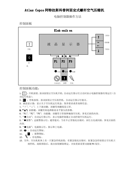
Atlas Copco 阿特拉斯科普柯固定式螺杆空气压缩机电脑控制器操作方法控制面板控制面板功能:1:开机按钮。
按该按钮让空压机开机,自动运行指示灯点亮时表示电脑控制器有效运行(自动运行状态)。
2,O :停机按钮。
按该按钮让空压机停机,自动运行指示灯熄灭。
3,液晶显示器:显示关于空压机运行状态,保养要求或者故障信息。
4,“↑”,“↓”:上下滚动键:该键用来翻阅显示屏。
5,“ 〓 ”:表格键:该键用来选择跟着水平箭头的参数。
6,“F1”,“F2”,“F3”:功能键:该键用于控制和编制空压机,参见后面的内容。
7,“●自动”:自动运行指示灯:表示电脑控制器正自动控制空压机运行。
8,“●报警”:总报警指示灯:通常熄灭,当有不正常情况出现时,该灯点亮或闪烁,参见后面的内容。
9,“●电源”:电源指示灯:指示和上电源。
10:自动运行图标。
11,:报警图标。
12,13,另外,空压机机体上有一只紧急停机按钮:有紧急情况出现时,按紧急急停按钮让空压机立刻停机,故障排除后,拔出按钮解除锁定,并按重新设置功能键F3复位。
1显示屏-键1.1 典型显示图1)前三行:——显示屏显示传感器的名称和实际的读数。
——测量值的单位和传感器的实际读数。
——关于空压机运行的信息(空压机停机,等等),保养要求(比如油过滤器和空气过滤器)或者是故障信息(比如故障停机)。
2)在四行位于三个功能键的上方(F1/F2/F3),显示这些键(F1/F2/F3)对应的实际功能。
1.2 滚动键(↑↓)这些滚动键标有垂直的箭头,允许滚动显示屏。
只要在显示屏的最右边的位置上有一个指向下面的箭头,其对应的滚动键就可以用来查阅下面的内容。
只要在显示屏的最右边的位置上有一个指向上面的箭头,其对应的滚动键就可以用来查阅前面的内容。
1.3 表格键( = )该键标有两个水平箭头,允许操作者选择标有水平箭头的参数。
只有后面跟着指向右面的箭头的参数才可以修改。
qgf 昆西螺杆空压机说明书

QGF 5.5 ~ 75 kW操作手册昆泰克空气系统技术有限公司Q-Tech Air System Technologies Co.Ltd.P/N :1625 1787 342011年03月第B 版目录部分Ⅰ-概论全警示标志 (1)安全预防措施 (2)备件的定购信息 (3)序列号/型号铭牌 (3)标准的保修内容 (4)部分Ⅱ-阐述概论 (5)压缩循环 (5)空气流动 (6)冷却系统 (6)控制系统 (7)电气系统 (11)电气原理图 (12)外形图 (23)控制流程图 (27)部分Ⅲ-安装设备的接受 (28)设备运至安装现场 (28)定位 (29)连接配管 (30)压力容器 (30)安全阀 (30)电气方面 (31)防护 (31)手动通风和截止阀 (31)压缩机的旋转 (31)风机旋转 (31)部分Ⅳ-操作程序启动之前 (32)启动压缩机 (32)停止压缩机 (33)控制面板的操作 (34)部分Ⅴ-维护维修和维护前的准备 (41)安全 (41)维护计划 (42)去除水分 (43)油气分离器滤芯 (43)空气过滤器 (44)压力设定 (44)油冷却器 (44)软管 (44)电机 (44)V型皮带驱动的维护 (45)电子控制 (50)空气和压缩机油的管道系统 (51)管接头安装 (51)部分Ⅵ-压缩机油压缩机油的规格 (52)压缩机油的液面高度 (53)压缩机油过滤器 (53)影响油使用寿命的因素 (54)压缩机油分析程序-常规 (54)QuinSyn PG (55)QuinSyn XP (56)QuinSyn Plus (57)QuinSyn Fluids (58)QuinSyn Flush (59)部分Ⅶ-故障的排除故障的排除 (60)o安全警示标志o安全预防措施o备件的定购信息o序列号/型号铭牌o标准的保修内容安全警示标志重要!本手册区别各重要危险标志,以下标志表明了危险的程度。
此标志表示当前会导致严重人身伤害、伤亡和严重财产损失的危险。
螺杆式空气压缩机设备操作说明书
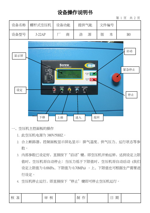
设备操作说明书
第 1 页 共 2 页
设备名称 螺杆式空压机 设备功能 提供气能 文件编号 设备型号 J-22AP
厂 商
劲 源
版 本
B0
一﹑空压机主控面板的操作
1. 此空压机电源为380V/50HZ 。
2. 合上断路器﹐控制面板显示屏处显示﹕排气温度﹑供气压力﹑运行状态等参
数。
3. 内部参数已设定好﹐直接按下“启动”键﹐即空压机开始运转﹐达到设定上限
值时﹐空压机将自动停止﹔当压力低于下限值时﹐空压机将自动启动 (我们设定上限值为0.8MPa ﹑下限值为0.70MPa) 。
上﹑下限值也可根据生产需要进行设定。
4. 空压机停止运行﹐即直接按下“停止”键即可停止空压机运行。
核 准
审 核 制 作 日 期
显示屏
停止
紧急停止
启动
下移
设定
上移
进入
返回
设备操作说明书
第 2 页共 2 页。
复盛空压机说明书
SINCE 1953SA SERIES使用手册INSTRUCTION MANUALSCREW AIR COMPRESSOR螺杆式空气压缩机复盛公司感谢您选用复盛牌螺杆空气压缩机!复盛公司对产品享有设计变更权,不对已出厂产品进行相应修改和改进。
说明:1.如不特别指明,本说明书中所指的压力均为表压力;2 .用户就保养、服务等有关压缩机的问题与本公司联系时,请指明机型和压力别,该内容在机器的铭牌上和保修卡上均有标识。
机组型号主机编号开机调试日期前言十分感谢您选用复盛牌螺杆空压机,本公司的产品在出厂前均已经过严格的检验与测试,但为确保机器能够安全、可靠、耐久地使用,请操作人员在机组运行前详细阅读本使用说明书,充分掌握该空压机组的操作规范和技能,使其设备长期处于良好的工作状态。
为了保证用户权益,请将设备质量保证卡寄回本公司服务部门,以便我公司能给予您及时的、最好的技术服务和售后服务。
谢谢!安全敬告在安全操作空压机前,请务必仔细阅读:安全注意事项:1.安装配管焊接时,需移开周围易燃物品,并注意防止焊接火花掉入空压机内,避免烧坏空压机某些部件;2.引到空压机的供电线径必须与其功率匹配(要考虑电线长度所引起的压降)并安装空气开关、熔断丝等安全装置,为确保电器设备的可靠安全,必须要有接地装置,必要时加装避雷装置;3.新机调试,必须由本公司指定或认可的调试人员进行;4.开机前应确认机组内无人,并检查是否有遗留物品和工具,关上机组门。
开机时,应先通知机组周围人员注意安全;5.第一次开机或电源线变动时,必须注意主机和风机转向是否按箭头指示方向运转;6.空压机不能在高于铭牌规定的排气压力下工作,否则会导致电机过载而烧坏;7.在空压机发生故障或有不安全因素存在时,切勿强行开机,此时应切断电源,并作出显著警示标志;8.压缩空气和电器都具有危险性,检修或维护保养时应确认电源已被切断,并在电源处挂“检修”或“禁止合闸”等警告标志,以防他人合闸送电造成伤害;9.停机维护必须关闭空压机机组对外供气相应隔离阀,且维护人员应避开空压机系统中的任何排气口把机组压缩空气安全释放完,等待空压机机组全部冷却后进行;10.清洗机组零部件时,应采用无腐蚀性的安全溶剂,严禁使用易燃易爆及易挥发的清洗剂;11.空压机运行一段时间后,须定期检查安全阀等保护系统,确保其灵敏可靠,安全阀必需定期进行鉴定(一般每年检验一次);12.空压机的零配件必须是正厂提供,其螺杆油必须为本公司指定复盛螺杆空压机高级冷却液,并且两种不同品牌的油严禁混用,否则会引起系统积炭造成重大事故;13.冬季空压机停止使用时,必须将油冷却器及后部冷却器中的冷却水完全排放干净,以防锈蚀和冻裂;14.空压机组应由固定人员操作,操作人员应通读并理解本说明书内容,遵循说明书中的工作程序和安全注意事项及维护规范。
阿特拉斯螺杆空压机说明书
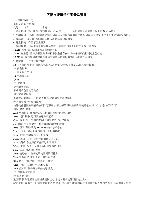
阿特拉斯螺杆空压机说明书一. 控制屏(图1.1)电脑显示屏/按钮/键代号名称功能1 停机按钮按此键停止空气压缩机,显示屏退出.空压机将空载运行大约30秒后停机.2 启动按钮按此按键启动空压机.显示屏显示调节器的运行状态.显示屏退出(如果空压机手动调为空载时)3 显示器显示出空压机的运转状态,协助需求或故障4 翻业按键在显示屏上翻页5 横移按键用水平箭头选择显示参数,只有向右的箭头对应的参数才能修改6 LED上的电压显示开关开启时的电压7 LED总报警当维护器警告或停机警告条件存在时或传感器不受控制时报警灯亮8 LED总在传感器的停机功能消失或紧急停机后的情况下报警灯会闪烁.9 功能键控制并执行程序.S3 紧急停机按钮在紧急情况下立即停止空压机,在修复后.将此按钮拔出.10 报警符号11 自动运行符号12 电源指示灯(1.1)二. 功能键使用的功能键:手动调节空压机的负荷调出或设定程序重新设定电动机的过负荷,停机,维护器信息或紧急停机.进入调节器所收集的数据.功能键都根据显示菜单的不同而不同.实际上都缩写并显示有关键的最底部一行,普通的缩写如下:缩写名称功能Add 增加指令用来增加空压机的自动启动/停机(日期)Back 返回指令返回到的选择或菜单Canc 取消当设定参数有误时.用来取消已设定的数dle 删除用来删除空压机的自动启动/停机时间Help 帮助帮助寻找Atlas Copco的内部地址Lim 上下限显示允许设定的上下极限数据Load 负载手动操作空压机负载Main 回到主目录从任一画面回到主目录Menu 菜单从主画面开始可进入子目录Menu 菜单从任一子目录返回到先前的目录Mod 修改修改设定参数Prog 编写输入将新的设定数据编写输入Rset 重新设定重新设定计时器及信息Rtrn 回归回归到前一页或前一目录Unld 空载手动操作空压机空载Xtra 额外的找寻调节器的构造模式三. 控制程序的功能程序/功能说明主屏幕简单地显示空压机的运转状态,是进入所有功能画面的出入口状态数据调出空压机的维护功能状况:停机.停机警告,维修期限快到的警告以及警告的数据,也可重新设定停机参数,马达超载和维修条件的数据.测量数据可调出:实际测量数据,还有如马达的超负荷保护这样一些输入数据计数器可调出:运行时间,带负荷运转小时数,马达开启次数,电脑运行时间数,负荷循环次数.试验试验显示屏修改设定修改以下设定:参数(如空载和负载时的压力)保护(如停机温度)维护计划.维护器调出维护计划并重新设定计时器已存数据调出上次关机,紧急停机时已存的数据1.5.2 主屏幕当开启电源开关时,主屏幕自动简单地显示空压机的操作状况.Delivery Air(输送空气)Bar(压力) 7.0 ↓Auto Loaded(自动负载)Menu(菜单) Unld(空载)F1 F2 F3如果功能键或↓几分钟不用的话显示屏就自动返回到主屏幕.无论在哪个子目录,只要按:Main就会返回到主目录.1.5.3 调出其他子菜单.从主目录开始: 用↓可快速浏览空压机的实际状态(见1.5.4节) .按Menu键(F1),供选择的数据就会跟在水平箭头后面:也可按横向移动箭头5来选择这个菜单或用↓来翻页到带有水平箭头的子目录为止,然后按水平键来选择这个菜单.1.5.4 迅速查看空压机的实际状态步骤1.从主目录开始(见1.5.2节),按↓键,就会显示相似下面的一个画面:Auto Operation(自动运转)Local Control(负荷控制)Tiner Active(激活计时器)Main (主画面) Help Xtra ↓F1 F2 F3图1.11所示为空压机实际状态显示第一行指出调节器的运行是自动还是手动的:<Auto Operation>表示调节器自动调节空压机的运转.如:Local(负载),Unlocal(空载),根据程序参数Sotp(停机)和 Restart(重启).<Man Operation>表示手动操作,如果在主屏幕上按了”Unload”键后调节器的自动压力控制就被打断了.第二行指出调节器是现场控制方式(Local control)还是远程控制方式(Remote control): <Local control>表示Start/Stop,load/unload(即开启/停止,负载/空载)的按钮是激活状态,可直接按.<Remote control>表示功能键是远方控制的,就地操作无效.第三行表示为计时器的开机停机命令是否在激活状态,见(1.15.13)2. 按↓键可以获得其它数据(如空压机的实际运行条件)1.5.5 状态数据菜单状态数据子目录给出了有关空压机保护功能的状态信息(如停机 .停机警告,维护器警告和一般警告)以及重新设定停止,马达超载和服务条件.步骤:从主屏幕开始(见1.5.2)按Menu(F1),用水平箭头选择状态数据.按横向移动键(LED中的5)1.5.5.1无信息存在在这种情况下,LED的7不存在,显示屏的信息表明所有条件正常(Fig1.12)All conditionsAre OKMenuF1 F2 F3图1.12状态数据屏的实例1.5.5.2 有停机信息存在在空压机停止时,LED中7会闪光.如果是由于空压机的出口温度过高导致的停机,就会显示以下屏幕: Element outletC 122Shd Max 120Menu** **RsetF1 F2 F3图1.13状态数据屏的实例1. 指示器(**)会闪光.屏幕显示传感器(空压机的出口)的实际可读温度(122℃),及空压机停机(Shd)设定(120℃).2. 可以继续翻页到其它菜单,检查其它参数值.当返回到数据菜单时,可供选择的(“Shutdowns”会闪光,按横向移动键5返回到停机屏幕来选择(“Shutdowns”).重新设定停机参数1. 关闭电源开关后处理问题,在修复完毕并且停机显示消失后,开启电源开关,按Rset(重新设定)键.2. 按Menu和 Main键返回主屏幕并按I键重新启动空压机.马达超载之重设1. 关闭电源开关并处理问题,过负荷继电器(F2)冷却后会自动重新设定,但冷却风扇的断路器(Q15)必须重置.开启电源开关,按Rset(重新设定)键.2. 按Menu和Main键返回主屏幕并重启空压机.1.5.5.3存在停机警告信息1.如有停机警告出现,LED上的7灯亮,会出现类似下面的屏幕:Delivery airBar 7.0*Shutd Warn*Menu** **UnldF1 F2 F3图1.14停机报警的实例2指示器(**)闪光和信息*Shutd Warn*会交替出现,无论空压机是空载还是带负载运行.3. 按Menu和横向移动键5来选择状态数据菜单:保护(Protection)会闪光.4. 按横向移动键5来选择报警闪光项.屏幕显示如下:Element outletC 116Shdw Max 110Menu** **F1 F2 F3图1.15停机报警的实例屏幕上说明空压机温度太高(116℃),参照第六节修复问题.5. 如有需要,按O键直到空压机停止为止.6. 关闭电源开关,检查并修复空压机.7. 当报警条件除去时,报警信号也会消失.1.5.5.4出现维护器报警信号1.LED上的7灯亮,会出现类似下面的屏幕,如图1.16所示:Delivery airBar 7.0*Serv Requir*Menu** **UnldF1 F2 F3图1.16报警屏幕的实例2指示器(**)闪光和维护器报警信号会交替出现,无论空压机是空载运行还是带负荷运行.3. 按Menu和横向移动键5来选择状态菜单:维护器项(Service),闪光4. 翻页并按横向移动键5来选择下面二报警闪光项:<Inputs>:如果维护器超出了预设的报警标准(如油分的最高压力露点).见8.2节.<Plans>:如果维护计划时间间隔超限.5. 停止空压机并关闭电源6. 如果维护器信息为上述的<Inputs>(油分故障):就更换分离器.开启电源,翻到状态数据菜单的<Inputs>并按Rset键,重新设定维护信息.7. 如果维护器信息为上述的<Plans>:执行有关指示计划的维修动作,重新设定1.5.15节里记述的有关计划的计时器.1.5.5.5 出现报警信号及处理1. LED上的7灯亮,在屏幕上会出现一个报警信息.2. 指示器(**)闪光和服务报警信号会交替出现,无论空压机是空载运行还是负荷运行.此警告指出:空压机的冷却水,冷却水的出口温度超过了设计报警温度.内置干燥机(配有干燥机的空压机),露点温度超出了报警温度.3. 停机4. 关闭电源,检查并修复空压机.1.5.6 测量数据菜单功能:按Menu(F1) 按↓到 Measured data 画面按横向移动箭头5激活菜单Delivery airBar 7.0Menu ↓F1 F2 F3图1.17状态数据屏的实例2按↓可见一组实际测量数据(见图1.9)3. 如果有一个传感器连接到了停机,维护器或报警功能上面的话,只要按横向移动箭头5就可以调出与其有关的实际测量数据.1.5.7 计数器菜单功能: 允许操作员调出:运行时间带负荷时间马达启动次数电脑运行时间步骤1. 从主屏幕开始(见1.5.2) 按Menu(F1)按↓到Counters画面按横向移动箭头5激活此菜单2. 按↓就可见到上面提到的数据.(也可见图1.9)1.5.8 试验菜单功能可修改图1.9提到的许多数据.步骤1. 从主屏幕开始(见1.5.2) 按Menu(F1)按↓到Modify setting画面,按横向移动箭头5激活菜单2. 水平箭头将指向Display test选项.3. 按→←第一条(负载压力)及它的设定都会出现4. 使用↓翻到水平箭头指向的已修改的参数.1.5.10.1 空/负载上下限压力修改压力段如果合适的话,操作员可以随空/负载压力的不同而设定二个压力段(1段和2段).1段的设定指示为:<Loading pressure>及<Unloading pressure>,2段的设定指示为:<Loading pressure2>及<Unloading pressure2>.例如:1 段压力设定:Loading pressur: 6.4barUnloading pressur: 7.0bar2 段压力设定:Loading pressur: 4.0barUnloading pressur: 6.0bar步骤1. 负载压力参数的设定1) 参照上节选择负载压力参数:Loading pressBar 6.0Menu Mod ↓F1 F2 F3图1.18为修改参数菜单3).Lim(F2)键可查看参数的上下限,用↓或↑调整压力参数值.4).按Prong(F1)编写输入新设定值,或按Canc(F3)取消修改操作.2. 修改空载压力的设定同上.3. 如果需要修改空/负载压力段2的话,则重复上述步骤..1.5.11 修改保护设定功能1. 修改保护设定停机保护(<Shd>)由于出口温度的问题停机警告(<Shdw>)由于出口温度的问题警告(<Warn>),如:冷却水回路或露点警告维护器报警(<Serv>),如:DP油分故障(最大压力降)2. 检查空压机的一些情况,如:马达超载通讯的状态.图1.9所示的参数表.注意:有些参数不能修改步骤1. 从主屏幕开始(见1.5.2)按Menu(F1)按↓到Modify setting画面,按横向移动箭头5激活此菜单2. 用↓翻页,水平箭头将指向Protection选项.3. 按→←第一条(Delivery air)及它的值都会出现.4. 使用↓翻到水平箭头指向的已修改的参数.1.5.11.1 温度上下限之设定修改1.参阅上节选择出口温度参数(Element outet):Element OutletC 94 →Shd Max 120Menu Mod ↓F1 F2 F3图1.20为修改参数菜单2.上屏幕显示的是正常温度94℃及停机温度120℃.按MOD(F2),数字120闪动,如图1.21所示: Element OutletC 120(闪动)Prog Lim Canc ↓F1 F2 F3图1.21为修改参数菜单3. Lim(F2)键可查看参数的上下限。
ANEST IWATA LRS系列螺杆式空压机 使用说明书

地址:上海市徐汇区宛平南路200号电话:021-6448-1059传真:021-6448-1184邮编:200030开始制造,销售往复式空压机1928无油往复式空压机1984进入了回转式空压机的领域1977无油螺杆式空压机1989低真空涡旋真空泵(DVSL)1997高真空涡轮分子泵真空机组 2001无油增压空压机2004无油旋齿式空压机(变频)2012发售世界最先进的无油涡旋空压机1991复合树脂制活塞的无油空压机2000制氮机2002通过了ISO140012007世界首发搭载7.5kW本体的无油涡旋式空压机2015发售LRS系列螺杆式空压机2017极致简约,外形时尚的LRS系列将LRL 系列机器使用的黑色更加突出表现极致追求无浪费的简约化及时尚产品品质油冷却器和后冷却器的面积增大冷却风扇、冷却器的布局变更冷却效率提高全系列搭载一目了然的操作面板各部品的交换周期、加载状况等空压机的详细状况可以确认显示语言可以设定中文、英文2种易见性·采用LRSV(变频机)+LRS(工频机)组合,降低初期成本,实现节能控制运行基于LRS+LRSV台数控制的空压机负载状况50%100%消耗空气量比率采用高品质变频控制器LRSV系列为软起动方式,高效节能节能性搭载IE3电机,大幅度提高效率,节省电费高效性降低10%(19,000元)年度电费降低30%(50,000元)产品式样标准机变频机如何舒适、高效的使用压缩机。
安全注意事项(关于压缩机的使用对象)● 请勿用于直接吸入压缩空气的呼吸器系统装置。
(会给人体造成重大的损伤。
特殊用途的情况下请垂询本公司。
)● 压缩机排出的气体中含有大气中的尘埃、各种气体、滑动部磨耗粉、储气罐的铁锈、水滴等。
●微油型压缩机的排出气体中含有油分,请对应设备安装油分去除装置(空气过滤器)。
● 储气罐的排水管内也含有铁锈,因此请每天实施排水作业。
(否则会造成排水管道堵塞。
)● 若用于重要的制造设备,当压缩机因保护装置动作而停止或发生故障时,请准备备用设备或替换装置加以对应。
螺杆式空压机开关机流程英文版
螺杆式空压机开关机流程英文版A screw-type air compressor is a critical component in many industrial and commercial operations, providing vital compressed air for various applications. The switch-on and switch-off processes for this type of air compressor are crucial for its efficient and safe operation.To start the screw-type air compressor, the operator first checks the oil level and ensures that there are no leaks or abnormalities in the system. Once the preliminary checks are complete, the operator turns on the main power switch and activates the control panel. The control panel allows the operator to set the desired pressure level and monitor the compressor's performance. With the settings in place, the operator then initiates the start-up sequence, allowing the compressor to build up pressure gradually.As the compressor reaches the set pressure level, the operator can then put it into full operation, allowing it to supply compressed air to the required equipment or machinery. During operation, the compressor's performance is monitored closely to ensure that it remains within safe parameters and operates efficiently.When it comes time to shut down the screw-type air compressor, the operator first depressurizes the system by releasing the compressed air in a controlled manner. Once the pressure is at a safe level, the operator can then proceed to turn off the compressor and the control panel. After powering down the main switch, the operator performs any required maintenance or checks to ensure that the compressor is in good working condition for the next operation.In conclusion, the switch-on and switch-off processes for a screw-type air compressor are essential steps in its operation. By following the proper procedures and maintainingthe equipment, operators can ensure the safe and efficient performance of the air compressor, contributing to the success of the overall industrial or commercial operation.。
BOGE空压机双螺杆压缩机操作说明书

BOGE空压机操作手册皮带驱动机构螺杆式压缩机S31~S340SD31~SD100长沙东工电源设备有限公司转译第一章节概论 (4)1.1 空气压缩机的安全指南 (4)1.2 空气压缩机保养和修理的安全指南 (5)1.3 预防事故规定 (6)1.4使用标记 (7)1.5 空气压缩机上的标记 (8)1.6 合理的使用 (8)1.7 不合理使用 (9)1.8运输损伤 (9)1.9铭牌上的数据 (9)1.10 服务 (10)第二章节产品描述 (10)2.1 技术数据 (10)S31~S100和SD31~SD100的技术数据,第一部分 (2)S101~S340的技术数据,第一部分 (3)S31~S100和SD31~SD100的技术数据,第二部分 (4)S101~S340的技术数据,第二部分 (5)2.2 功能描述 (6)压缩转子工作原理 (6)空气循环 (6)油路循环 (7)2.3 压缩机控制 (8)出口压力 (8)操作状态 (8)操作模式 (8)短时间操作 (9)2.4 控制设备 (9)容调控制或称作无级控制 (9)2.5 安全操作装置 (10)概论 (10)压缩室温度监控器 (10)安全阀门 (10)监视传动马达和风扇马达 (11)传动方向监视(增选项) (11)安全—压力开关器(增选项) (11)系统压力构成(增选项) (11)2.6 水冷却系统 (12)串联 (12)冷却水的连接 (13)冷却水水质 (13)第三章节安装 (2)3.1 运输 (2)概论 (2)运输方法 (2)3.2 尺寸 (3)操作和保养的空间要求S31~S100 (3)3.3 机房 (8)储气罐的安装,保养条件和使用目的 (8)安装地面 (8)防火措施 (8)防噪音措施 (8)环境条件 (9)防冻措施 (9)冷却气流的输入和排出 (9)冷却风量 (10)机房通风的方法 (11)冷凝液的处理 (11)3.4 安装 (12)概论 (12)安装空气压缩机 (12)连接压缩机和系统 (12)连接冷却水(增选项) (13)拆卸运输紧固插销 (13)使皮带张力装置生效 (14)检查机油情况 (14)3.5 电路连接 (15)3.6 试车启动 (16)检验马达运转方向 (16)打开阀门 (16)检查泄漏 (16)试车工作 (16)长时间停机后试车 (17)冷冻式空气干燥机 (17)第四章节控制系统 (18)4.1 Boge公司ARS控制系统的概念 (18)概论 (18)微电脑 (18)模块化构成 (18)4.2 操作和控制面板 (2)4.3 操作元件 (3)4.5 操作 (6)4.6 信息查询 (8)4.7 故障报警信息表 (10)4.8 控制参数 (11)概述 (11)参数设置步骤 (11)输入参数代码 (11)设置空压机保养周期和重启计数器 (11)设置马达保养周期和重启计数器 (12)设置运转部件保养的循环次数 (12)改变目标压力值(P MAX和P MIN) (12)外接输出有效 (12)切换就地—远程控制 (13)远程开停控制 (14)改变空车延时 (14)设置连续模式 (15)复电自动开机 (15)RS-485总线地址设置 (15)参数一览表 (16)操作元件SD31~SD100冷冻式干燥机排水系统 (17)第二章第五章节故障处理 (1)控制系统的自我监控 (1)5.2 普通故障 (3)第三章第六章节功能结构 (1)6.1 平面热量交换器BOGE-DUOTHERM BPT (1)功用 (1)安装 (1)启动 (2)保养 (2)6.2 安全热量交换器BOGE-DUOTHERM BSW (3)功用 (3)启动 (3)保养 (3)第七章节保养 (4)7.1 安全指导 (4)7.2 Boge服务部的保养工作 (5)定期性的保养工作 (5)保养间隔期 (6)关于润滑油的常用指南 (7)机油的后处理 (7)备品和易损件 (7)7.3 常规保养工作 (8)清洁或更换进气过滤器 (8)清洁过滤筒 (8)更换进风口过滤网(增选项) (9)润滑驱动马达轴承 (10)持久性润滑的驱动马达 (10)带有润滑装置的驱动马达 (10)更换皮带 (11)GM马达传动系统的安装规格 (12)检查油量/加注机油 (13)更换油过滤器 (14)更换油气分离器 (15)换油 (17)清洗油路 (19)清洗冷却器 (19)清洗油冷却器(水冷却) (20)检查和调整操作压力变送器 (21)无级控制或者称作容调控制(增选项) (21)检查安全阀门 (22)7.4 备品和增选设备 (23)备品易损件表 (23)增选部件表 (24)第八章节附录 (2)8.1 流程图 (2)SD31~SD100 (3)SD31~SD100/Plus (3)平面热量交换器BOGE-DUOTHERM BPT (5)安全热量交换器BOGE-DUOTHERM-PLUS BSW (5)8.2 保养和服务记录 (6)第一章节概论用户须知:忽视安全的话将会导致人身的伤害或者空气压缩机的损坏。
- 1、下载文档前请自行甄别文档内容的完整性,平台不提供额外的编辑、内容补充、找答案等附加服务。
- 2、"仅部分预览"的文档,不可在线预览部分如存在完整性等问题,可反馈申请退款(可完整预览的文档不适用该条件!)。
- 3、如文档侵犯您的权益,请联系客服反馈,我们会尽快为您处理(人工客服工作时间:9:00-18:30)。
Contents1.0 Products (2)2.0 Security (2)3.0 general description (4)4.0 Technical Specifications (6)5.0 installation requirements and start-up inspection before (7)6.0 operating (10)7.0 Options (13)8.0 maintenance (14)Intelligent control systems that operate (21)Screw-type air compressor Manual (36)1.0 ProductsScrew-type air compressor structure of a unique design, a compact, stylish appearance, high efficiency, small energy consumption, low noise characteristics and long life, is a smart environment-friendly products. Is widely applied in metallurgy, machinery, chemicals, and mining, and electric power industries of the ideal gas source equipment.It has:The third generation of advanced rotorConcise intake control systemEfficient centrifugal separator oil and gas, gas oil content is extremely small, tube and core of long lifeEfficient, Low Noise Suction fan of the full use of export dynamic pressure increased effect of heat transfer (air-cooled)Automatic water-cooling system for large air compressor to provide more efficient heat transfer capacity (water-cooled)Packaging materials so that the noise to the minimum level of noise attenuation Fault diagnosis system, the control panel is easy to operateRemovable door, equipment maintenance, service convenientMicro-electronic processing so that temperature, pressure and other parameters are closely monitoredShow-controlled instrument used (standard) and PLC-controlled liquid crystal display (intelligent), two forms of electrical control, have a variety of monitoring protectionNo one realized fully automatic operation, intelligence operations, and remote control and linkage controlThe operation manual is to help users get the best results, must be read carefully before operating. On the proper use and maintenance plan, will extend the service life and reduce air compressor failure.Note: All the relevant information, services and spare parts directly with the customer service department or its authorized agents mechanical linkages.2.0 Security2.1 GeneralAir compressor designed to take fully into account the safety of operators, but operators must ultimately be responsible for their own safety. Below the security measures only as a guidance, is aimed at the use of air compressor in the process of harm reduction.Not operate under unsafe conditions for air compressor. In maintenance, air compressor should be marked temporarily unable to work and cut off power supply, This will prevent the misuse of others caused injuries.2.2 Personal Protective EquipmentWork long hours in the air compressor next to the operators must wear ear protectors.2.3 Pressure1, the removal of the oil filter, air compressor should be in a state of downtime, and no pressure (to be down five minutes before the removal of the oil filter). 2, in the open any pipe, valves, Mentou, joints, as well as related parts, should eliminate internal pressure.3, the Ministry of technology has not been agreed, not to alter the pressure settings. 4, not to damage or removal of safety valve.5, under any circumstances, do not direct the flow of the body or cooling the air. 6, under any circumstances, not to compressed air directly in front of their own any part of the body.2.4 Fire, explosion-proof1, should immediately clean flying out of lubricants and other flammable and explosive materials.2, flammable and explosive items must be away from the air compressor, air compressor next to the smoking ban.3, cables and connectors to maintain clean, bonded and Terminals.4, to ensure good air compressor operation, the use of special lubricants and spare parts.5, air compressor should be in a good ventilation or hot-air row of the installation work. (Otherwise, hot air temperature will rise)2.5 Mobile and the protection of rotating machinery1, the release of the clothing and any part of the body are not close to fans and other rotating parts.2, in the maintenance of air compressors, power must be shut down to prevent accidental launch.3, in the absence of protection of the gate, not to start machines.2.6 Dangerous surfaceAvoid physical and thermal fluid, heat and the exhaust pipe of contact with the surface, to avoid scalding.2.7 Hazardous Substances1, do not breathe the air out from the air compressor.2, compressed air is not directly at anyone.1, the air compressor when the application-oriented hoisting rope, twisting to prevent bad air compressor. After lifting to check whether the welds and bolts loose.2, if the trailer is flat handling, should ensure that the trailers have enough flat-panel power to drag the air compressor.3, if the forklift is used to handling, should also ensure that the forklift has sufficient power, according to the specific situation to the local requirements.2.9 Personnel in the prevention of machines shut down withinIf the air compressor within the very large space (to accommodate), in the air compressor to work outside the marked, and must cut off power and placed obvious signs.2.10 Operation1, air compressor acoustic enclosures optimize the structural design of the cooling air flow (under normal circumstances, the door was opened, should not boot).2, open-air compressor can not work unless the provision of specialized equipment to maintain the open.3, if the air compressor leakage, please do not start up, should contact customer service.Tip: When the air compressor running time should be installed first acoustic home3.0 General d escriptionScrew the screw air compressor rotor is manufactured in accordance with international standards, the use of asymmetric linear design, to ensure that the use of all energy consumption and the smallest gain the maximum amount of compressed air. Air compressor is modular in design, screw rotor, oil and gas separation extinguishers, coolers, are installed in a motor, within the framework of acoustic enclosures through the noise of rubber materials.3.1 Principle of operationScrew air compressor is the main components of screw head, the separation of oil and gas cylinder. Screw suction filter through the nose and suction inlet control valve, oil also inject compressed room, a cooling of the nose, while the screw and the bearings lubricated by compressed air pressure that is generated.Compressed gas mixture of oil and gas production, oil and gas emissions to the separation barrel. Centrifugal force in the machinery and the role of gravity, the majority of the oil from the oil and gas separated from the gas mixture. Residual fuel-air after the separation of oil and gas no longer be separated from the core. Separated from the core oil and gas separation of the oil filter, clean the oil return to the work of screw head cavity.When the oil is separated, compressed air into the minimum pressure valve after coolers,Minimum pressure valve to maintain the normal operation at the start and oil pressure on Circulating the required minimum.3.2 Control SystemControl system is aimed at controlling the intake valve open, to ensure the normal flow of air. The system includes an intake valve, a Detroit, two electromagnetic valve. 1, the start: When you launch air compressor, by the spring of the intake valve is closed to the role. So empty air compressor in the case started, only a small amount of air through air controllers for one-way valve be inhaled, the establishment of cavity pressure to ensure that the oil cycle.2, to load: When the air compressor to load up and running (running) state, is a vacuum within the compressor, air filters, pressure, pressure to both the intake valve piston operation, intake valve open. With the air into the intake valve to open all, the pressure increased.3, a full load: When oil and gas from the cylinder pressure reached 40 KPa, the minimum pressure valve opened, compressed air outflow. (As long as the system pressure than the pressure setting, intake valve has been opened)4, unloading: when the pressure pipeline to set up pressure, the pressure switch to the electromagnetic valve off, compressors and air filter of the Inner Mongolia Autonomous Region have no pressure. Spring on the role of intake valve will be closed. Exhaust electromagnetic valve action, separation of oil and gas cylinder to reduce the pressure on so that the screw head lower back pressure. Unloading when a small amount of air into to maintain a certain pressure to ensure that the oil pressure of work so that the rotor, the bearings lubricated. When the pipeline pressure dropped to set the load pressure, the air compressor return to the loading state. Electromagnetic valve power, the intake valve open, the pressure increased. Based on the needs of compressed air, repeat cycle of the process.5, stands: When the air compressor downtime, all of the electromagnetic valve off, the intake valve closed, the pressure through the barrel of electromagnetic exhaust pressure relief valve.3.3 Jin temperatureAir compressor design operating temperature for 5 ℃ to 50 ℃, measuring point is the air entry points.3.3.1 Condensation - CoolIn the relatively high humidity, and lower operating temperature than when condensed water easily gathered in the oil. Wen Kongfa air compressor with a temperature set at 70 ℃(This is the steam necessary for the evaporation temperature), when the oil temperature, oil temperature higher than that before the oil cooler. In the ambient temperature below 5 ℃ areas, use of the machine, under the requirements of oil and gas separation extinguishers installed heater (please contact the Department of Technology).When the ambient temperature at 50 ℃ or more, or the installation of a boiler room, use the machine, inhaled air must be introduced from the outside.Air compressor maximum operating temperature is 105 ℃, must be based on manual to find the reasons for the failure, or contact customer service.3.3.3 Discharge temperatureTemperature temperature of the exhaust air compressor set point in the exhaust port. According to the exhaust temperature is the ambient temperature, the cooler the cleanliness, air filter and the cleanliness of the oil filter change in the cleanliness. Normal operating temperature of 70 ℃ to be between 90 ℃.In the cold start-up, quickly exhaust temperature rose to 85 ℃, Wen Kongfa fully open (Wen Kongfa action began at 70 ℃). When the oil temperature back to 70 ℃, when Wen Kongfa will bypass part of the oil to prevent oil temperature is too low. Wen Kongfa is to control the oil cooler to regulate the oil discharge temperature.4.0 Technical Specifications4.1 Electrical characteristicsIntelligent Unit optional SCK PLC, and its main features are:1, SCK is the latest award-winning, solid and compact plastic casing, easy wiring, control and, with the former mask to protect components.2, through the mounting holes or DIN rails can be installed vertically or horizontally in the cabinet, the terminal row as a fixed wiring accessories (optional).3, data security in the internal EEPROM storage users of the original procedures and scheduled, and in a longer time period (typically 190 hours), all intermediate data can maintain a super-capacitors.4, Profibus DP network control and the use of near-unanimous far, the maximum transfer rate of up to 12 Mbit/s.4.2 Of lubricantsScrew Compressors for oil has the following characteristics:foaming low and difficult to volatilerole of strong anti-emulsifyinghigh antioxidantcampaign viscosity (40 ℃) mm2 / s 28-35has a good anti-wear lubricity, anti-foam and water separationcondensate temperature -20 ℃, to prevent the curing performance, lower power consumptionflash point temperature of 200 ℃, to prevent the formation of carbon deposition performance, lower power consumptionhigh stability, can significantly prolong life, reduce maintenance cycle andHuanyouzhouqi, good adaptabilityScrew air compressor for oil, screw machine is based on the principle of special and exclusive distribution of air compressor oil, in order to ensure the normal useof air compressor, screw air compressor selected for oil.⇩Note: clients for the use of other brands of oil caused the problem, the company does not undertake any responsibility.4.2.1 bearing motor oilBearing the air compressor motor oil recommended Shell Alvania RL 3 fats.Note: do not lead to the correct installation of durability failure5.0 installation requirements and start-up checkBefore installing the air compressor, double-check whether the transport of the damage caused. If it is found that significantly damaged, immediately contact customer service.5.1 location request1, air compressor should be placed in a clean, no dust in the air and non-poisonous gas, flammable, explosive gases and well-ventilated occasions, and to facilitate maintenance work.2, open-air compressor can not be used, unless the compressor is installed with the open-air options, all the air compressor must be installed in the indoor (or increase shelf covered).3, poor outdoor environment, dust, should be in the room air into the rough validity of the outlet installed filters to reduce indoor dust content.4, the temperature must be greater than the 5 ℃, lubricants to ensure the normal cycle.5, the surrounding air compressor must have a certain space, one meter away from the wall for good, so that operators of day-to-day operation, maintenance and overhaul. 6, air compressor must be placed at the level of hard ground, not bolt fixed.Tip: Do not install air compressor in the vicinity of the hot air. From the exhaust pipe from the hot air, the cycle can not be inhaled. (The air compressor in a ventilated places)5.2 cooling requirements1, to prevent the emission of hot air re-inhalation2, the smallest air resistance3, to reduce suction vacuum4, the same room to install multiple air compressor, please contact customer service5, poorly ventilated rooms, the need to install ventilation and exhaust pipe6, machine outdoor installation, the machines must be installed at the top of Yupeng, or other open-air installation of devices7, to consider each of the suction machine outlet from the other machines will not exhaust the suction mouth8, plate-fin heat exchanger emission of air can not be promptly dispersed, it will affect the temperature of the surrounding air compressor, the proposed use of exhaust pipe (no exhaust pipe and tube planes, which can not be greater than the pressure drop of 30 Pa, and Pai Wind pressure can not be in the air compressor).Note: taking into account the cooling effect, to a well-ventilated rooms (if not enough cooling capacity, will lead the indoor temperature rise, leading to overheated air compressor). Paying particular attention to the cooler is to prevent the emission of air being inhaled. The installation of new machinery and start-up, please contact customer service.5.3 pair of water-cooling unit, cooling water quality requirements1, total hardness CaCo3 used to be that less than 100 PPM (100 mg/l)2, PH value of between 6 to 83, suspension of not more than 50 PPM (50 mg/l)Tip: Cooling water temperature is designed to 32 ℃, water quality must be consistent with the general industrial water to avoid the use of groundwater, if the poor water quality and cleaning agents to regularly remove fouling. The following winter at the freezing point, stands a long time, cooling water must be clean emissions.5.4 Pipeline system connecting the air requirements1, piping, require exhaust pipe with a diameter of at least diameter of the exhaust pipe of the compressor, all pipes and fittings should be able to withstand the rated pressure, appropriate allocation of the gas flow requirements so that the pipeline pressure drop no more than set pressure air compressor 5%, in line to minimize the use of the elbow and drag coefficient of components, longer pipeline, the best choice of the design value than the diameter.2, to avoid condensation of water in the pipeline along the pipeline flow to the work machine or pneumatic components, should be set up in front of their water and gas separation plant and sewage installations. Road charge of piping, the pipe must have one or two degrees of tilt, for the benefit of the condensate pipeline from the cold water.3, the exit of the compressor, a one-way valve should be installed and the closing valves, then there should be pressure on the sampling population, with maintenance of the cut-off valve, in order to access the hose, with maintenance work.4, due to a compressor base Earthquake pads, no fixed the support of all the external piping must have its own independent support. Pipeline installation to be considered downtime, will not return to the condensed water into the air compressor. (Pipeline connecting the air compressor air compressor shall not exceed the Export I)5, supporting the use of compressors and dryers, the ideal piping system is in between the compressor and the installation of a dryer cylinders, this could be caused by gas compressor cooling and isolated part of condensed water. After cylinders at the same time, low temperature and Hanshui Fen less compressed air transport into the dryer, you can reduce the load dryer, saving energy consumption.6, the ideal trial for the allocation and use of gas around the entire plant, this can have access to any location in both the compressed air, and in the appropriate configuration around the main line on the valve, so as to help cut maintenance purposes.5.5 electrical installation requirements and electrical inspection1, all the wires have been in the air compressor factory testing, access the external air compressor wires must use qualified manufacturers of wires, according to compressors necessary for the importation of power, the correct choice of the power cord specifications. When the power cable lines long, the line losses to be considered at this time should be bold diameter to meet the air compressor up and running. 2, the displacement compressor should be considered a separate power supply system, so as not to affect the commencement of the compressor other devices work properly. 3, air compressor in the power supply voltage to be confirmed with the compressor rated voltage line.4, compressors must do a good job in a reliable grounding line, to prevent leakage and dangerous.Tip: the machine started on the panel marked electrical schematics.5.5.1 PowerStandard requirements:380V, 3 phase, 50 Hz groundingSpecial requirements in order when⇩Note: air compressor its own transformer, do not need the center line.5.5.2 Motor toIn testing motor to the former, familiar with the manual of Chapter 6.Electric power and the right to access, to ensure that the right motor. Air compressor with a motor to prevent reversal of the special device (if the three-phase phase sequence wrong, the electrical automatic shutdown to protect the motor).Specific methods are as follows: Access to power, release the emergency shutdown button, the machine self-inspection; on the start button, the electrical operating normally, the three-phase progressive correct.Motor automatic shutdown of the sequence is wrong, and the two pairs of input current exchange (and not to replace the starter motor coil and the coil, these coils are factory optimization of the use of motor performance and configuration, can not be changed). The electrical wiring of electrical work must have a certificate from the staff to complete.5.6 mechanical testing5.6.1 screw head of the inspection1, from two different directions manually rotating the screw head pulley or coupling, the screw head has not been confirmed locked.2, down more than 12 months when the air compressor or storage after a period of time must be open intake valve, through the inlet valve control by adding a half litre of oil. From two different directions manually rotating the screw head pulley or coupling to ensure that all oil into the screw head.3, then again into the trachea, to ensure the mouth sealed.5.6.2 oil-inspectionOpen the side door, we can see that oil and gas from the oil-barrel, oil must not be lower than under the standard oil, in the same operation. (efueling by the highest oil-mouth restrictions)By adding the oil provision to ensure that the lid Gaijin efueling mouth, the right ring can be sealed.5.6.3 Transmission System inspection (belt or patch-coupling)1, belt checksCheck all the belts are in bed, by adjusting the screw head of the adjustment bolt to adjust the tightness of the belt. (Normal adjustment method, see 8.7)2, patch-coupling of inspectionCheck whether the patch in the coupling bolts fastening the state.5.6.4 inspection system in all the valvesThe deadline for check valve is open.Note: Please refer to Chapter 6 of the correct procedures for start-up6.0 OperationThe following procedure is the first launch air compressor, air compressor, or stop using more than two months on the operational procedures.6.1 preparations for the pre-bootEquipped with advanced air compressor from stopping delay functions, which together with the air compressor assembly, would serve to protect the electrical, screw nose relay, to optimize system performance.1, the start delayedThis function is to avoid blackouts or after the emergency shutdown of the motor consecutive start. During this time, the air compressor could not be activated to ensure that the system to reduce the pressure to prevent a back-pressure compressor in the case started.In this period of time by the start button, the system will automatically record the signal, such as delay time that the air compressor will be automatically activated. 2, stands DelayThis is a soft-shutdown feature, which allows air compressor unloading stands. The shutdown button, air compressor unloading, running for a pre-set time after the shutdown. (This will help to reduce the pressure on oil and gas separation cylinder) This delay in the stop for a period of time according to boot button to stop automatically delay the end of this time, as long as the system pressure to load andoffload and normal air compressor.6.2 initial start-up procedures1, please read the manual in front of the section;2, all the preparation and start-up inspection should be strictly in accordance with Chapter 5 of the standard to implement;3, check whether the export of cut-off valve open (open the valve once the deadline, show that the pressure is the pressure);4, connected to power, power indicator light, the compressor started delayed, ban immediately launched air compressor;5, the start button (to ensure that the right - see 5.4.2), the air compressor is the delayed implementation of the normal start, once the pre-set the start-up time that the air compressor that is automatically activated. (In the delay time, the stop button down)6, observe the operation of the control panel on the temperature and pressure systems, the proper operation of air compressor (see 3.1);7, when the pressure to set up after the pressure switch moves, air compressor running, but running on empty state;8, through the air compressor to load, unload cycles and gas field, the operation must pay attention to pressure, temperature fluctuations and the current situation; 9, to ensure the smooth operation of machinery, no accidents vibration;Tip: the vibration machine accidents, stands contact customer service.6.2.1 peacetime startup procedures1, check the oil-is correct, the oil in the oil must be the subject of the middle; 2, the condensed water discharge cylinders;3, the deadline for confirmation valve open;4, the start button: (air compressor is not automatically activated in the running lights flashing, that delay in the launch air compressor)⇩Note: in the stands within 60 seconds, do not start machinery, oil and gas must be completely separated barrel pressure release (to prevent a back-pressure compressor in the case started).6.2.2 shutdown proceduresAs long as the shutdown button, air compressor started delay stands, and then prepare for the indicators lights flashing. After a period of time, the air compressor to automatically stop.If the air compressor has been in operation stands by full stands after the stop button. ⇩Note: air compressor in the state by plane may be downtime, may also be activated at some point, even if the motor did not turn down that should not be read by the light of whether or not lit.Tip: emergency shutdown button, generally used only for the state of emergency.6.3 functional control6.3.1 StandardStandard air compressor of monitoring devices in the air compressor before the panel at the top. The control panel of the state machinery such as the following shows, there are three in the control panel digital display and a pressure gauge. Digital display shows a screw head exhaust ports of temperature, pressure gauges instructions minimum pressure control valve after the pressure.Control board in a standard feature:emergency shutdown button (out of control when the hard stands)launch buttonshutdown button (delay soft shutdown feature)hours of servicetemperature figures show that oil and gas monitorsbefore the filter pressure gaugeexhaust pressure gaugeAdvanced monitoring board in the additional functions:power instructionsoperation instructionsigh-temperature oil and gas instructionsmain electrical overload instructionsuninstall instructionsair filter by blocking instructionscore oil and gas from the cylinder block instructionsoil filter by blocking instructionsFans have contained instructionswater directives6.3.2 on the use of intelligent operationPlease refer to Help Control System6.4 pressure control switchThe initial design of the factory table:Normal operating pressure(KPa)Normal operatingpressure(KPa)Cut Pressure(KPa)Pressure tocut(KPa)Adjustablepressure to cut(KPa)Adjustablepressure to cut(KPa)700 60 650 710 650 720800 70 730 800 730 8001000 80 920 1000 870 950Air compressor to increase the pressure on exports, the corresponding motor will increase the pressure, the air compressor to raise the pressure on exports, he must contact customer service⇩Note: without the technology sector agreed that the unauthorized export pressure to change the air compressor caused the problem, not liable6.5 high-temperature shutdownAir compressor equipped with high-temperature protection device6.5.1 screw head of the high-temperature protectionAir compressor equipped with digital monitoring display devices, if the temperature reaches rotor export 105 ℃ (This is the factory settings, can not be changed), air compressor downtimeWhen the high-temperature alarm, they should even take measures to identify reasons for troubleshooting.High-temperature shutdown after launch air compressor, must be re-confirmed (and other machines after cooling), the boot is now before the shutdown button.Tip: If fault can not be ruled out, this may be due to an internal temperature is also very high, in this case, air compressor must be cooled down.6.6 motor overload protectionAir compressor motors are equipped with temperature overload protection device, when the motor temperature too much time, temperature overload protection for movements to air compressor downtime. When this happens, the starter for the internal protection devices must be reconfirmed. Cut off power supplies, electronic control box open, click on the reset button on the device, find a place to solve problems.Note: Please other electrical contact with local suppliers6.7 Wen KongfaWhen the air compressor from the cold at the start of the emissions, the temperature will quickly rise around 82 ℃, Wen Kongfa all open at this time, if the load relatively small, oil temperature will be maintained at around 70 ℃. Wen Kongfa goalkeeper bypass without oil cooler to prevent the oil temperature is too low. When the load increased, oil temperature will rise, then Wen Kongfa will be part of the oil through the oil coolers, air compressor to maintain the ideal temperature to work⇩Note: correct settings will not damage air compressor, the company irresponsible7.0 OptionsBelow the option to order requests targeted under the Factories7.1 Lord, by way of ControlWhen the air compressor tandem with work, need a master / preparation of control, the main air compressor to provide the main gas source. Not enough to supply the main air compressor, air compressor by the work of preparing the main air compressor in a set time conversion (one day or a week)When more than one series of air compressor when the exhaust pipe must be careful layout. Incorrect pipe layout will air compressor in the condensed water gathered in charge of road, empty or flow back to prepare for the state of the air compressor. Overall air compressor Export mouth with the location of the high-mouth。
