M30853FJFP中文资料
开合安装式互感器

※可以按用户需求定做
等级
0.1、0.2
0.1、0.2
5
0.1、0.2
0.1、0.2
0.1、0.2
0.1、0.2
0.1、0.2
0.1、0.2
0.1、0.2
0.1、0.2
0.1、0.2
0.5
0.2
0.1
上一个产品
下一个产品
返回产品目录
哈尔滨三达德电力技术有限公司 销售热线:0451-86786010 网址: E-mail:sale@
开合安装式电流互感器外形图....................................................................................................................................................... 15
开合安装式电流互感器
产品目录
哈尔滨三达德电力技术有限公司 二零一零年十一月
开合安装式电流互感器
目录
目录 .................................................................................................................................................................................................... 1 开合安装式电流互感器简介............................................................................................................................................................. 2 开合安装式电流互感器产品明细..................................................................................................................................................... 3
三相电源4杆可拔电路保护器产品说明书
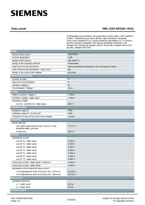
● at 415 V / rated value
● at 500 V / rated value
● at 690 V / rated value
breaking capacity maximum short-circuit current (Icu)
● at 415 V / rated value
● at 500 V / rated value
number of NC contacts / for auxiliary contacts
number of NO contacts / for auxiliary contacts
Suitability
suitability for use
Product details
product component
● at 690 V / rated value
Connections
arrangement of electrical connectors / for main current circuit
type of electrical connection / for main current circuit
Current operational current ● at 40 °C / rated value ● at 45 °C / rated value ● at 50 °C / rated value ● at 55 °C / rated value ● at 60 °C / rated value ● at 65 °C / rated value ● at 70 °C / rated value continuous current / rated value / maximum continuous current / rated value adjustable current response value current ● of instantaneous short-circuit trip unit / minimum ● of instantaneous short-circuit trip unit / maximum
FP30系列可编程数码调节器操作说明书V3
超过额定范围会导致升温,缩短本仪表的寿命并有可能引起故障。 ● 本仪表为了散热多处开有通风口。
如果金属等异物混入通风口会引起本仪表的故障,请千万注意。通风口请保持清洁通 畅,避免粉尘阻塞,导致升温和绝缘劣化,使本仪表寿命缩短,甚至引起故障。 ● 重复进行耐电压,耐干扰,耐浪涌电压等极限实验会引起本仪表的劣化,请注意。 ● 禁止用户对本仪表进行改装或不当使用。 ● 为正确使用本仪表,维护本仪表的信赖和品质,请您务必遵守操作手册中所载的注意 事项。 ● 操作本仪表前面的按键时,请用手指轻按,切勿用硬物或尖头的物体操作。 ● 清扫本仪表时,请用柔软的干布轻拭,切勿使用稀释剂等溶剂清洁。
6
基本窗口组...................................................................................................................................... 17
3&4&5ʗ36/ 转换
ൺྫप ظ
仪ද্电ঢ়态设ஔ
FP30 ྻܥ໘൘҆ํ๏
Ճ热ثஅ线报ܯ电ྲྀ检测ثʢCTʣతईੇ
ఔং步Ⴋ༨时间显ࣔ
iv
确认产品内容
本仪表出货前经过严格的品质检查。收到本仪表后,请确认仪表的外观和型号代码是否与你订购的一致,附
件是否齐全,产品是否有报损等。
确认型号代码
请确认仪表外壳粘帖的型号编码是否和您当初在选型表中选择订购的内容一致。
确认附件
三汇示波器说明书(Ver1.0)
DST4000 和 DST1000 系列数字存储示波器用户手册
i
目录
5.1 显示区 ........................................................................................ 20 5.2 信息区域..................................................................................... 23 5.3 波形显示..................................................................................... 23
三汇系列产品
DST4000 和 DST1000 系列 数字存储示波器
Version 1.0
杭州三汇科技有限公司 www.
目录
目录
目 录 ...........................................................................................................i 版权申明 .......................................................................................................................................................................v 第 1 章 安全事项......................................................................................... 1
霖叶 BL8530 开关型 DC DC 升压稳压器 选型指南说明书
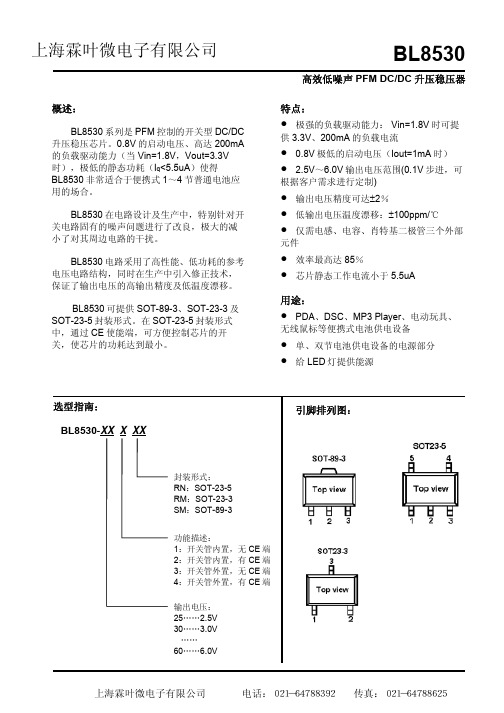
高效低噪声PFM DC/DC 升压稳压器BL8530概述:BL8530系列是PFM 控制的开关型DC/DC 升压稳压芯片。
0.8V 的启动电压、高达200mA的负载驱动能力(当Vin=1.8V ,Vout=3.3V 时),极低的静态功耗(I q <5.5uA )使得BL8530非常适合于便携式1~4节普通电池应用的场合。
BL8530在电路设计及生产中,特别针对开关电路固有的噪声问题进行了改良,极大的减小了对其周边电路的干扰。
BL8530电路采用了高性能、低功耗的参考电压电路结构,同时在生产中引入修正技术,保证了输出电压的高输出精度及低温度漂移。
BL8530可提供SOT-89-3、SOT-23-3及SOT-23-5封装形式。
在SOT-23-5封装形式中,通过CE 使能端,可方便控制芯片的开关,使芯片的功耗达到最小。
特点:• 极强的负载驱动能力: Vin=1.8V 时可提供3.3V 、200mA 的负载电流• 0.8V 极低的启动电压(Iout=1mA 时)• 2.5V ~6.0V 输出电压范围(0.1V 步进,可根据客户需求进行定制) • 输出电压精度可达±2%• 低输出电压温度漂移:±100ppm/℃• 仅需电感、电容、肖特基二极管三个外部元件• 效率最高达85%• 芯片静态工作电流小于5.5uA用途:• PDA 、DSC 、MP3 Player 、电动玩具、无线鼠标等便携式电池供电设备 • 单、双节电池供电设备的电源部分 •给LED 灯提供能源上海霖叶微电子有限公司 BL8530引脚定义表引脚号符号引脚描述SOT-89-3SOT-23-3 SOT-23-51 1 4 Vss(GND)接地引脚2 2 2 Vout输出电压监测,内部电路供电引脚3 3 5 Lx(Ext)开关引脚-- 3 NC 空脚-- 1 CE 使能端产品命名目录产品名称输出电压规格开关管 CE端封装形式V 内置无SOT-89-3BL8530-XX1SM XXBL8530-XX1RM XXV 内置无SOT-23-3V 内置有SOT-23-5BL8530-XX2RN XXBL8530-XX3SM XXV 外置无SOT-89-3BL8530-XX3RM XXV 外置无SOT-23-3BL8530-XX4RN XXV 外置有SOT-23-5系统框图:产品的极限参数输入电压------------------------------------------------------------------------------------------------0.3V~12VLx脚开关电压------------------------------------------------------------------------------------------0.3V~(Vout+0.3) CE脚电压-----------------------------------------------------------------------------------------------0.3V~(Vout+0.3) Lx脚输出电流-----------------------------------------------------------------------------------------0.7A允许的最大功耗,Pd T=25°CSOT-89-3------------------------------------------------------------------------------------------0. 5WSOT-23-5------------------------------------------------------------------------------------------0.15WSOT-23-3------------------------------------------------------------------------------------------0.15W最大工作结温-----------------------------------------------------------------------------------------150°C工作温度----------------------------------------------------------------------------------------------- -20~+80°C存贮温度----------------------------------------------------------------------------------------------- -40~125°C焊接温度和时间--------------------------------------------------------------------------------------260°C,10S推荐工作条件名称最小 推荐 最大 单位输入电压范围 0.8 Vout V 电感值10 27 100 µH 输入电容值 0 ≥10µF 输出电容值* 47 100 220 µF 工作环境温度 -20 85 ℃*:建议使用钽电容以减小输出电压的开关纹波。
M30302GCPFP资料
M16C/30P GroupSINGLE-CHIP 16-BIT CMOS MICROCOMPUTER REJ03B0088-0122Rev.1.22Mar 30, 20071.OverviewThe M16C/30P Group of single-chip microcomputers is built using the high-performance silicon gate CMOS process using a M16C/60 Series CPU core and is packaged in a 100-pin plastic molded QFP.These single-chip microcomputers operate using sophisticated instructions featuring a high level of instruction efficiency. With 1 Mbyte of address space, they are capable of executing instructions at high speed. In addition, these microcomputers contain a multiplier and DMAC which combined with fast instruction processing capability, make it suitable for control of various OA, communication, and industrial equipment which requires high-speed arithmetic/ logic operations.1.1ApplicationsAudio, cameras, TV, home appliance, office/communications/portable/industrial equipment, etc.1.2Performance OutlineTable 1.1 lists Performance Outline of M16C/30P Group.NOTES:1.I 2C bus is a registered trademark of Koninklijke Philips Electronics N. V.2.IEBus is a registered trademark of NEC Electronics Corporation.e the M16C/30P on VCC1 = VCC2.Table 1.1Performance Outline of M16C/30P GroupItem PerformanceCPU Number of Basic Instructions 91 instructionsMinimum Instruction Execution Time 62.5ns(f(XIN)=16MHz, VCC1=VCC2=3.0 to 5.5V, no wait)100ns(f(XIN)=10MHz, VCC1=VCC2=2.7 to 5.5V, no wait)Operation Mode Single-chip, memory expansion and microprocessormodeMemory Space 1 Mbyte Memory Capacity See Table 1.2 Product ListPeripheral Function Port Input/Output : 87 pins, Input : 1 pin Multifunction Timer Timer A : 16 bits x 3 channels,Timer B : 16 bits x 3 channelsSerial Interface 1 channelsClock synchronous, UART, I 2CBus (1), IEBus (2)2 channelsClock synchronous, UART, I 2CBus (1)A/D Converter 10-bit A/D converter: 1 circuit, 18 channels DMAC 2 channels CRC Calculation Circuit CCITT-CRC Watchdog Timer 15 bits x 1 channel (with prescaler)Interrupt Internal: 20 sources, External: 7 sources, Software: 4sources, Priority level: 7 levelsClock Generating Circuit 2 circuitsMain clock generation circuit (*), Subclock generation circuit (*),(*)Equipped with a built-in feedback resistor.Electric Characteristics Supply Voltage VCC1=VCC2=3.0 to 5.5 V (f(XIN)=16MHz)VCC1=VCC2=2.7 to 5.5 V (f(XIN)=10MHz, no wait)Power Consumption 10 mA (VCC1=VCC2=5V, f(XIN)=16MHz)8 mA (VCC1=VCC2=3V, f(XIN)=10MHz)1.8 μA (VCC1=VCC2=3V, f(XCIN)=32kHz, wait mode)0.7 μA(VCC1=VCC2=3V, stop mode)One time flash versionProgram Supply Voltage 3.3±0.3 V or 5.0±0.5 V Flash memory version Program/Erase Supply Voltage3.3±0.3 V or 5.0±0.5 V Program and Erase Endurance100 times (all area)Operating Ambient Temperature -20 to 85°C, -40 to 85°C Package 100-pin plastic mold QFP , LQFP1.3Block DiagramFigure 1.1 is a M16C/30P Group Block Diagram.1.4Product ListTable 1.2 lists the M16C/30P group products and Figure 1.2 shows the Part No., Memory Size, and Package. Table 1.4 lists Product Code of MASK ROM version for M16C/30P. Figure 1.3 shows the Marking Diagram of Mask ROM Version for M16C/30P (Top View). Table 1.5 lists Product Code of One Time Flash version, Flash Memory version, and ROM-less version for M16C/30P. Figure 1.4 shows the Marking Diagram of One Time Flash version,Flash Memory version, and ROM-less Version for M16C/30P (Top View). Please specify the marking for M16C30P (MASK ROM version) when placing an order for ROM.(D): Under development (P): Under planning NOTES:1.Previous package codes are as follows.PRQP0100JB-A : 100P6S-A, PLQP0100KB-A : 100P6Q-A2.Block A (4-Kbytes space) is available in flash memory version.Table 1.2Product List (1)As of March 2007Part No.ROM Capacity RAM Capacity package code (1)Remarks M30302MAP-XXXFP 96 Kbytes 5 KbytesPRQP0100JB-A Mask ROM versionM30302MAP-XXXGP PLQP0100KB-A M30302MCP-XXXFP 128 Kbytes PRQP0100JB-A M30302MCP-XXXGP PLQP0100KB-A M30302MDP-XXXFP 160 Kbytes 6 Kbytes PRQP0100JB-A M30302MDP-XXXGP PLQP0100KB-A M30302MEP-XXXFP 192 Kbytes PRQP0100JB-A M30302MEP-XXXGP PLQP0100KB-A M30302GAPFP 96 Kbytes 5 Kbytes PRQP0100JB-A One Time Flash version(blank product)M30302GAPGP (D)PLQP0100KB-A M30302GCPFP 128 Kbytes PRQP0100JB-A M30302GCPGP (D)PLQP0100KB-A M30302GDPFP 160 Kbytes 6 Kbytes PRQP0100JB-A M30302GDPGP (D)PLQP0100KB-A M30304GDPFP (D)12 Kbytes PRQP0100JB-A M30304GDPGP (D)PLQP0100KB-A M30302GEPFP 192 Kbytes 6 Kbytes PRQP0100JB-A M30302GEPGP (D)PLQP0100KB-A M30304GEPFP (D)12 KbytesPRQP0100JB-A M30304GEPGP (D)PLQP0100KB-A M30302GGPFP (D)256 Kbytes 12 Kbytes PRQP0100JB-A M30302GGPGP(D)PLQP0100KB-A M30302GAP-XXXFP 96 Kbytes5 Kbytes PRQP0100JB-A One Time Flash version(factory programmed product)M30302GAPvGP (D)PLQP0100KB-A M30302GCP-XXXFP 128 Kbytes PRQP0100JB-A M30302GCP-XXXGP (D)PLQP0100KB-A M30302GDP-XXXFP 160 Kbytes 6 Kbytes PRQP0100JB-A M30302GDP-XXXGP (D)PLQP0100KB-A M30304GDP-XXXFP (D)12 Kbytes PRQP0100JB-A M30304GDP-XXXGP (D)PLQP0100KB-A M30302GEP-XXXFP 192 Kbytes 6 Kbytes PRQP0100JB-A M30302GEP-XXXGP (D)PLQP0100KB-A M30304GEP-XXXFP (D)12 KbytesPRQP0100JB-A M30304GEP-XXXGP (D)PLQP0100KB-A M30302GGP-XXXFP (D)256 Kbytes12 Kbytes PRQP0100JB-A M30302GGP-XXXGP(D)PLQP0100KB-ATable 1.3Product List (2)As of March 2007(D): Under development (P): Under planning NOTES:1.Previous package codes are as follows.PRQP0100JB-A : 100P6S-A, PLQP0100KB-A : 100P6Q-A2.Block A (4-Kbytes space) is available in flash memory version.Part No.ROM Capacity RAM Capacity package code (1)Remarks M30302FAPFP 96 K + 4 Kbytes 5 KbytesPRQP0100JB-A Flash memory version (2)M30302FAPGP PLQP0100KB-A M30302FCPFP 128 K + 4 Kbytes PRQP0100JB-A M30302FCPGP PLQP0100KB-A M30302FEPFP 192 K + 4 Kbytes 6 Kbytes PRQP0100JB-A M30302FEPGP PLQP0100KB-A M30302SPFP - 6 Kbytes PRQP0100JB-A ROM-less versionM30302SPGPPLQP0100KB-ATable 1.4Product Code of MASK ROM version for M16C/30P Product Code Package Operating Ambient Temperature U1 Lead-free-20°C to 85°CU4 -40°C to 85°CNOTES:The one time flash version can be written once only.Version for M16C/30P (Top View)Table 1.5Product Code of One Time Flash version, Flash Memory version, and ROM-less version for M16C/30PProduct CodePackageInternal ROMOperating Ambient TemperatureProgram and Erase EnduranceTemperature RangeOne Time Flash version U3 Lead-free 00°C to 60°C -40°C to 85°CU5 -20°C to 85°C Flash Memory versionU3 Lead-free 1000°C to 60°C -40°C to 85°C U5 -20°C to 85°C ROM-less versionU3Lead-free −−-40°C to 85°C U5 -20°C to 85°C1.5Pin ConfigurationFigures 1.5 to 1.6 show the pin configurations (top view).Table 1.6Pin Characteristics (1)Pin No.ControlPin Port Interrupt Pin Timer Pin UART Pin Analog PinBus ControlPinFP GP199P9_6ANEX12100P9_5ANEX031P9_442P9_353P9_2TB2IN64P9_1TB1IN75P9_0TB0IN86BYTE97CNVSS108XCIN P8_7119XCOUT P8_61210RESET1311XOUT1412VSS1513XIN1614VCC11715P8_5NMI1816P8_4INT21917P8_3INT12018P8_2INT02119P8_12220P8_02321P7_72422P7_62523P7_5TA2IN2624P7_4TA2OUT2725P7_3TA1IN CTS2/RTS22826P7_2TA1OUT CLK22927P7_1TA0IN RXD2/SCL23028P7_0TA0OUT TXD2/SDA23129P6_7TXD1/SDA13230P6_6RXD1/SCL13331P6_5CLK13432P6_4CTS1/RTS1/CTS0/CLKS13533P6_3TXD0/SDA03634P6_2RXD0/SCL03735P6_1CLK03836P6_0CTS0/RTS03937P5_7RDY/CLKOUT 4038P5_6ALE4139P5_5HOLD4240P5_4HLDA4341P5_3BCLK4442P5_2RD4543P5_1WRH/BHE 4644P5_0WRL/WR 4745P4_7CS34846P4_6CS24947P4_5CS15048P4_4CS0Table 1.7Pin Characteristics (2)Pin No.Control Pin Port Interrupt Pin Timer Pin UART Pin Analog Pin Bus Control Pin FP GP5149P4_3A195250P4_2A185351P4_1A175452P4_0A165553P3_7A155654P3_6A145755P3_5A135856P3_4A125957P3_3A116058P3_2A106159P3_1A96260VCC26361P3_0A86462VSS6563P2_7A76664P2_6A66765P2_5A56866P2_4A46967P2_3A37068P2_2A27169P2_1A17270P2_0A07371P1_7D157472P1_6INT4D147573P1_5INT3D137674P1_4D127775P1_3D117876P1_2D107977P1_1D98078P1_0D88179P0_7AN0_7D78280P0_6AN0_6D68381P0_5AN0_5D58482P0_4AN0_4D48583P0_3AN0_3D38684P0_2AN0_2D28785P0_1AN0_1D18886P0_0AN0_0D08987P10_7KI3AN79088P10_6KI2AN69189P10_5KI1AN59290P10_4KI0AN49391P10_3AN39492P10_2AN29593P10_1AN19694AVSS9795P10_0AN09896VREF9997AVCC10098P9_7ADTRG1.6Pin DescriptionI : Input O : Output I/O : Input and outputTable 1.8Pin Description (1)Signal Name Pin Name I/O Type DescriptionPower supply input VCC1, VCC2VSS I Apply 2.7 to 5.5 V to the VCC1 and VCC2 pins and 0 V to the V SSpin. The VCC apply condition is that VCC1 = VCC2.Analog power supply input AVCC AVSS I Applies the power supply for the A/D converter. Connect the AVCCpin to VCC1. Connect the AVSS pin to VSS.Reset input RESET I The microcomputer is in a reset state when applying “L” to the thisVSSCNVSSI Switches processor mode. Connect this pin to VSS to when aftera reset to start up in single-chip mode. Connect this pin to VCC1 to start up in microprocessor mode.External data bus width select inputBYTEI Switches the data bus in external memory space. The data bus is16 bits long when the this pin is held "L" and 8 bits long when the this pin is held "H". Set it to either one. Connect this pin to VSS when an single-chip mode.Bus control pins D0 to D7I/O Inputs and outputs data (D0 to D7) when these pins are set as theseparate bus.D8 to D15I/O Inputs and outputs data (D8 to D15) when external 16-bit data busis set as the separate bus.A0 to A19O Output address bits (A0 to A19).CS0 to CS3O Output CS0 to CS3 signals. CS0 to CS3 are chip-select signals tospecify an external space.WRL/WR WRH/BHE RDOOutput WRL, WRH, (WR, BHE), RD signals. WRL and WRH or BHE and WR can be switched by program.• WRL, WRH and RD are selectedThe WRL signal becomes "L" by writing data to an even address in an external memory space.The WRH signal becomes "L" by writing data to an odd address in an external memory space.The RD pin signal becomes "L" by reading data in an external memory space.• WR, BHE and RD are selectedThe WR signal becomes "L" by writing data in an external memory space. The RD signal becomes "L" by reading data in an external memory space.The BHE signal becomes "L" by accessing an odd address.Select WR, BHE and RD for an external 8-bit data bus.ALE O ALE is a signal to latch the address.HOLD I While the HOLD pin is held "L", the microcomputer is placed in a hold state.HLDA O In a hold state, HLDA outputs a "L" signal.RDYIWhile applying a "L" signal to the RDY pin, the microcomputer is placed in a wait state.Table 1.9Pin Description (2)Signal Name Pin Name I/O Type DescriptionMain clock input XIN I I/O pins for the main clock generation circuit. Connect a ceramicresonator or crystal oscillator between XIN and XOUT. To use theexternal clock, input the clock from XIN and leave XOUT open.Main clockoutputXOUT OSub clock input XCIN I I/O pins for a sub clock oscillation circuit. Connect a crystal oscillatorbetween XCIN and XCOUT. To use the external clock, input the clockfrom XCIN and leave XCOUT open.Sub clockoutputXCOUT OClock output CLKOUT O The clock of the same cycle as fC, f8, or f32 is outputted. INT interruptinputINT0 to INT4I Input pins for the INT interrupt.NMI interruptinputNMI I Input pin for the NMI interrupt.Key inputinterrupt inputKI0 to KI3I Input pins for the key input interrupt.Timer A TA0OUT toTA2OUT I/O These are timer A0 to timer A2 I/O pins. (however, the output of TA0OUT for the N-channel open drain output.)TA0IN to TA2IN I These are timer A0 to timer A2 input pins. Timer B TB0IN to TB2IN I These are timer B0 to timer B2 input pins.Serial interface CTS0 to CTS2I These are send control input pins.RTS0 to RTS2 O These are receive control output pins.CLK0 to CLK2I/O These are transfer clock I/O pins.RXD0 to RXD2I These are serial data input pins.TXD0 to TXD2O These are serial data output pins. (however, TXD2 for the N-channelopen drain output.)CLKS1O This is output pin for transfer clock output from multiple pins function.I2C mode SDA0 to SDA2I/O These are serial data I/O pins. (however, SDA2 for the N-channelopen drain output.)SCL0 to SCL2I/O These are transfer clock I/O pins. (however, SCL2 for the N-channelopen drain output.)Referencevoltage inputVREF I Applies the reference voltage for the A/D converter.A/D converter AN0 to AN7,AN0_0 to AN0_7I Analog input pins for the A/D converter.ADTRG I This is an A/D trigger input pin.ANEX0I/O This is the extended analog input pin for the A/D converter, and is theoutput in external op-amp connection mode.ANEX1I This is the extended analog input pin for the A/D converter.I/O port P0_0 to P0_7,P1_0 to P1_7,P2_0 to P2_7,P3_0 to P3_7,P4_0 to P4_7,P5_0 to P5_7,P6_0 to P6_7,P7_0 to P7_7,P9_0 to P9_7,P10_0 to P10_7I/O8-bit I/O ports in CMOS, having a direction register to select an input or output.Each pin is set as an input port or output port. An input port can be setfor a pull-up or for no pull-up in 4-bit unit by program. (however, P7_0and P7_1 for the N-channel open drain output.)P8_0 to P8_4,P8_6, P8_7I/O I/O ports having equivalent functions to P0.Input port P8_5I Input pin for the NMI interrupt. Pin states can be read by the P8_5 bitin the P8 register.I : Input O : Output I/O : Input and output2.Central Processing Unit (CPU)Figure 2.1 shows the CPU registers. The CPU has 13 registers. Of these, R0, R1, R2, R3, A0, A1 and FB comprise a register bank. There are two register banks.2.1Data Registers (R0, R1, R2 and R3)The R0 register consists of 16 bits, and is used mainly for transfers and arithmetic/logic operations. R1 to R3 are the same as R0.The R0 register can be separated between high (R0H) and low (R0L) for use as two 8-bit data registers.R1H and R1L are the same as R0H and R0L. Conversely, R2 and R0 can be combined for use as a 32-bit data register (R2R0). R3R1 is the same as R2R0.2.2Address Registers (A0 and A1)The register A0 consists of 16 bits, and is used for address register indirect addressing and address register relative addressing. They also are used for transfers and logic/logic operations. A1 is the same as A0.In some instructions, registers A1 and A0 can be combined for use as a 32-bit address register (A1A0).2.3Frame Base Register (FB)FB is configured with 16 bits, and is used for FB relative addressing.2.4Interrupt Table Register (INTB)INTB is configured with 20 bits, indicating the start address of an interrupt vector table.2.5Program Counter (PC)PC is configured with 20 bits, indicating the address of an instruction to be executed.2.6User Stack Pointer (USP) and Interrupt Stack Pointer (ISP)Stack pointer (SP) comes in two types: USP and ISP, each configured with 16 bits.Your desired type of stack pointer (USP or ISP) can be selected by the U flag of FLG.2.7Static Base Register (SB)SB is configured with 16 bits, and is used for SB relative addressing.2.8Flag Register (FLG)FLG consists of 11 bits, indicating the CPU status.2.8.1Carry Flag (C Flag)This flag retains a carry, borrow, or shift-out bit that has occurred in the arithmetic/logic unit.2.8.2Debug Flag (D Flag)The D flag is used exclusively for debugging purpose. During normal use, it must be set to “0”.2.8.3Zero Flag (Z Flag)This flag is set to “1” when an arithmetic operation resulted in 0; otherwise, it is “0”.2.8.4Sign Flag (S Flag)This flag is set to “1” when an arithmetic operation resulted in a negative value; otherwise, it is “0”.2.8.5Register Bank Select Flag (B Flag)Register bank 0 is selected when this flag is “0” ; register bank 1 is selected when this flag is “1”.2.8.6Overflow Flag (O Flag)This flag is set to “1” when the operation resulted in an overflow; otherwise, it is “0”.2.8.7Interrupt Enable Flag (I Flag)This flag enables a maskable interrupt.Maskable interrupts are disabled when the I flag is “0”, and are enabled when the I flag is “1”. The I flagis cleared to “0” when the interrupt request is accepted.2.8.8Stack Pointer Select Flag (U Flag)ISP is selected when the U flag is “0”; USP is selected when the U flag is “1”.The U flag is cleared to “0” when a hardware interrupt request is accepted or an INT instruction for software interrupt Nos. 0 to 31 is executed.2.8.9Processor Interrupt Priority Level (IPL)IPL is configured with three bits, for specification of up to eight processor interrupt priority levels from level 0 to level 7.If a requested interrupt has priority greater than IPL, the interrupt is enabled.2.8.10Reserved AreaWhen write to this bit, write “0”. When read, its content is indeterminate.M16C/30P Group 3. Memory3.MemoryFigure 3.1 is a Memory Map of the M16C/30P group. The address space extends the 1 Mbyte from address 00000h to FFFFFh.The internal ROM is allocated in a lower address direction beginning with address FFFFFh. For example, a 64-Kbyte internal ROM is allocated to the addresses from F0000h to FFFFFh.The fixed interrupt vector table is allocated to the addresses from FFFDCh to FFFFFh. Therefore, store the start address of each interrupt routine here.The internal RAM is allocated in an upper address direction beginning with address 00400h. For example, a 5-Kbyte internal RAM is allocated to the addresses from 00400h to 017FFh. In addition to storing data, the internal RAM also stores the stack used when calling subroutines and when interrupts are generated. The SFR is allocated to the addresses from 00000h to 003FFh. Peripheral function control registers are located here. Of the SFR, any area which has no functions allocated is reserved for future use and cannot be used by users.The special page vector table is allocated to the addresses from FFE00h to FFFDBh. This vector is used by the JMPS or JSRS instruction. For details, refer to the M16C/60 and M16C/20 Series Software Manual.4.Special Function Register (SFR)SFR(Special Function Register) is the control register of peripheral functions. Tables 4.1 to 4.5 list the SFR information.NOTES:1.The blank areas are reserved and cannot be accessed by users.2.The PM00 and PM01 bits do not change at software reset.X : Nothing is mapped to this bitTable 4.1SFR Information (1) (1)Address RegisterSymbolAfter Reset0000h 0001h 0002h 0003h 0004h Processor Mode Register 0 (2)PM000000000b(CNVSS pin is “L”)00000011b(CNVSS pin is “H”)0005h Processor Mode Register 1PM100XXX0X0b 0006h System Clock Control Register 0CM001001000b 0007h System Clock Control Register 1CM100100000b 0008h Chip Select Control RegisterCSR 00000001b 0009h Address Match Interrupt Enable Register AIER XXXXXX00b 000Ah Protect RegisterPRCRXX000000b000Bh 000Ch 000Dh 000Eh Watchdog Timer Start Register WDTS XXh000Fh Watchdog Timer Control Register WDC 00XXXXXXb 0010h Address Match Interrupt Register 0RMAD000h 0011h 00h 0012h X0h 0013h 0014h Address Match Interrupt Register 1RMAD100h 0015h 00h 0016h X0h0017h 0018h 0019h 001Ah 001Bh 001Ch 001Dh 001Eh 001Fh 0020h DMA0 Source Pointer SAR0XXh 0021h XXh 0022h XXh 0023h 0024h DMA0 Destination Pointer DAR0XXh 0025h XXh 0026h XXh 0027h 0028h DMA0 Transfer Counter TCR0XXh 0029h XXh002Ah 002Bh 002Ch DMA0 Control Register DM0CON 00000X00b002Dh 002Eh 002Fh 0030h DMA1 Source Pointer SAR1XXh 0031h XXh 0032h XXh 0033h 0034h DMA1 Destination Pointer DAR1XXh 0035h XXh 0036h XXh 0037h 0038h DMA1 Transfer Counter TCR1XXh 0039h XXh003Ah 003Bh 003Ch DMA1 Control Register DM1CON 00000X00b003Dh 003Eh 003FhTable 4.2SFR Information (2) NOTES:1.The blank areas are reserved and cannot be accessed by users.2.This register is included in the flash memory version.3.This register is included in the flash memory version and one time flash version. X : Nothing is mapped to this bitAddress RegisterSymbolAfter Reset0040h 0041h 0042h 0043h 0044h INT3 Interrupt Control RegisterINT3IC XX00X000b 0045h 0046h UART1 BUS Collision Detection Interrupt Control Register U1BCNIC XXXXX000b 0047h UART0 BUS Collision Detection Interrupt Control Register U0BCNIC XXXXX000b 0048h 0049h INT4 Interrupt Control RegisterINT4IC XX00X000b 004Ah UART2 Bus Collision Detection Interrupt Control Register BCNIC XXXXX000b 004Bh DMA0 Interrupt Control Register DM0IC XXXXX000b 004Ch DMA1 Interrupt Control Register DM1IC XXXXX000b 004Dh Key Input Interrupt Control RegisterKUPIC XXXXX000b 004Eh A/D Conversion Interrupt Control Register ADIC XXXXX000b 004Fh UART2 Transmit Interrupt Control Register S2TIC XXXXX000b 0050h UART2 Receive Interrupt Control Register S2RIC XXXXX000b 0051h UART0 Transmit Interrupt Control Register S0TIC XXXXX000b 0052h UART0 Receive Interrupt Control Register S0RIC XXXXX000b 0053h UART1 Transmit Interrupt Control Register S1TIC XXXXX000b 0054h UART1 Receive Interrupt Control Register S1RIC XXXXX000b 0055h Timer A0 Interrupt Control Register TA0IC XXXXX000b 0056h Timer A1 Interrupt Control Register TA1IC XXXXX000b 0057h Timer A2 Interrupt Control RegisterTA2ICXXXXX000b0058h 0059h 005Ah Timer B0 Interrupt Control Register TB0IC XXXXX000b 005Bh Timer B1 Interrupt Control Register TB1IC XXXXX000b 005Ch Timer B2 Interrupt Control Register TB2IC XXXXX000b 005Dh INT0 Interrupt Control Register INT0IC XX00X000b 005Eh INT1 Interrupt Control Register INT1IC XX00X000b 005Fh INT2 Interrupt Control Register INT2IC XX00X000b0060h to 01AFh 01B0h 01B1h 01B2h 01B3h 01B4h 01B5h Flash Memory Control Register 1 (2)FMR10X00XX0Xb 01B6h 01B7h Flash Memory Control Register 0 (3) FMR000000001b01B8h 01B9h 01BAh 01BBh 01BCh 01BDh 01BEh 01BFh 01C0h to 024Fh 0250h 0251h 0252h 0253h 0254h 0255h 0256h 0257h 0258h 0259h 025Ah 025Bh 025Ch 025Dh 025Eh Peripheral Clock Select Register PCLKR 00000011b025Fh 0260h to 033FhTable 4.3SFR Information (3)Address Register Symbol After Reset 0340h0341h0342h0343h0344h0345h0346h0347h0348h0349h034Ah034Bh034Ch034Dh034Eh034Fh0350h0351h0352h0353h0354h0355h0356h0357h0358h0359h035Ah035Bh035Ch035Dh035Eh Interrupt Factor Select Register 2IFSR2A00XXXXXXb035Fh Interrupt Factor Select Register IFSR00h0360h0361h0362h0363h0364h0365h0366h0367h0368h0369h036Ah036Bh036Ch UART0 Special Mode Register 4U0SMR400h036Dh UART0 Special Mode Register 3U0SMR3000X0X0Xb036Eh UART0 Special Mode Register 2U0SMR2X0000000b036Fh UART0 Special Mode Register U0SMR X0000000b0370h UART1 Special Mode Register 4U1SMR400h0371h UART1 Special Mode Register 3U1SMR3000X0X0Xb0372h UART1 Special Mode Register 2U1SMR2X0000000b0373h UART1 Special Mode Register U1SMR X0000000b0374h UART2 Special Mode Register 4U2SMR400h0375h UART2 Special Mode Register 3U2SMR3000X0X0Xb0376h UART2 Special Mode Register 2U2SMR2X0000000b0377h UART2 Special Mode Register U2SMR X0000000b0378h UART2 Transmit/Receive Mode Register U2MR00h0379h UART2 Bit Rate Generator U2BRG XXh037Ah UART2 Transmit Buffer Register U2TB XXh037Bh XXh037Ch UART2 Transmit/Receive Control Register 0U2C000001000b037Dh UART2 Transmit/Receive Control Register 1U2C100000010b037Eh UART2 Receive Buffer Register U2RB XXh037Fh XXhNOTES:1.The blank areas are reserved and cannot be accessed by users.X : Nothing is mapped to this bitTable 4.4SFR Information (4)Address Register Symbol After Reset 0380h Count Start Flag TABSR000XX000b0381h Clock Prescaler Reset Fag CPSRF0XXXXXXXb 0382h One-Shot Start Flag ONSF00XXX000b0383h Trigger Select Register TRGSR XXXX0000b 0384h Up-Down Flag UDF XX0XX000b (2) 0385h0386h Timer A0 Register TA0XXh0387h XXh0388h Timer A1 Register TA1XXh0389h XXh038Ah Timer A2 Register TA2XXh038Bh XXh038Ch038Dh038Eh038Fh0390h Timer B0 Register TB0XXh0391h XXh0392h Timer B1 Register TB1XXh0393h XXh0394h Timer B2 Register TB2XXh0395h XXh0396h Timer A0 Mode Register TA0MR00h0397h Timer A1 Mode Register TA1MR00h0398h Timer A2 Mode Register TA2MR00h0399h039Ah039Bh Timer B0 Mode Register TB0MR00XX0000b039Ch Timer B1 Mode Register TB1MR00XX0000b039Dh Timer B2 Mode Register TB2MR00XX0000b039Eh039Fh03A0h UART0 Transmit/Receive Mode Register U0MR00h03A1h UART0 Bit Rate Generator U0BRG XXh03A2h UART0 Transmit Buffer Register U0TB XXh03A3h XXh03A4h UART0 Transmit/Receive Control Register 0U0C000001000b03A5h UART0 Transmit/Receive Control Register 1U0C100000010b03A6h UART0 Receive Buffer Register U0RB XXh03A7h XXh03A8h UART1 Transmit/Receive Mode Register U1MR00h03A9h UART1 Bit Rate Generator U1BRG XXh03AAh UART1 Transmit Buffer Register U1TB XXh03ABh XXh03ACh UART1 Transmit/Receive Control Register 0U1C000001000b03ADh UART1 Transmit/Receive Control Register 1U1C100000010b03AEh UART1 Receive Buffer Register U1RB XXh03AFh XXh03B0h UART Transmit/Receive Control Register 2UCON X0000000b03B1h03B2h03B3h03B4h03B5h03B6h03B7h03B8h DMA0 Request Factor Select Register DM0SL00h03B9h03BAh DMA1 Request Factor Select Register DM1SL00h03BBh03BCh CRC Data Register CRCD XXh03BDh XXh03BEh CRC Input Register CRCIN XXh03BFhNOTES:1.The blank areas are reserved and cannot be accessed by users.2.Bit 5 in the Up-down flag is “0” by reset. However, The values in these bits when read are indeterminate.X : Nothing is mapped to this bitTable 4.5SFR Information (5)Address Register Symbol After Reset03C0h A/D Register 0AD0XXh03C1h XXh03C2h A/D Register 1AD1XXh03C3h XXh03C4h A/D Register 2AD2XXh03C5h XXh03C6h A/D Register 3AD3XXh03C7h XXh03C8h A/D Register 4AD4XXh03C9h XXh03CAh A/D Register 5AD5XXh03CBh XXh03CCh A/D Register 6AD6XXh03CDh XXh03CEh A/D Register 7AD7XXh03CFh XXh03D0h03D1h03D2h03D3h03D4h A/D Control Register 2ADCON2XXX000X0b03D5h03D6h A/D Control Register 0ADCON0000X0XXXb03D7h A/D Control Register 1ADCON100000XXXb03D8h03D9h03DAh03DBh03DCh03DDh03DEh03DFh03E0h Port P0 Register P0XXh03E1h Port P1 Register P1XXh03E2h Port P0 Direction Register PD000h03E3h Port P1 Direction Register PD100h03E4h Port P2 Register P2XXh03E5h Port P3 Register P3XXh03E6h Port P2 Direction Register PD200h03E7h Port P3 Direction Register PD300h03E8h Port P4 Register P4XXh03E9h Port P5 Register P5XXh03EAh Port P4 Direction Register PD400h03EBh Port P5 Direction Register PD500h03ECh Port P6 Register P6XXh03EDh Port P7 Register P7XXh03EEh Port P6 Direction Register PD600h03EFh Port P7 Direction Register PD700h03F0h Port P8 Register P8XXh03F1h Port P9 Register P9XXh03F2h Port P8 Direction Register PD800X00000b03F3h Port P9 Direction Register PD900h03F4h Port P10 Register P10XXh03F5h03F6h Port P10 Direction Register PD1000h03F7h03F8h03F9h03FAh03FBh03FCh Pull-Up Control Register 0PUR000h03FDh Pull-Up Control Register 1PUR100000000b (2)00000010b (2)03FEh Pull-Up Control Register 2PUR200h03FFh Port Control Register PCR00hNOTES:1.The blank areas are reserved and cannot be accessed by users.2.At hardware reset, the register is as follows:• “00000000b” where “L” is inputted to the CNVSS pin• “00000010b” where “H” is inputted to the CNVSS pinAt software reset, the register is as follows:• “00000000b” where the PM01 to PM00 bits in the PM0 register are “00b” (single-chip mode).• “00000010b” where the PM01 to PM00 bits in the PM0 register are “01b” (memory expansion mode) or “11b” (microprocessor mode). X : Nothing is mapped to this bit。
防雷器工业用

Surge Protection System M300系列防雷器使用说明书深圳市华捷能科技有限公司总目录一.公司简介 (3)二.安全守则 (4)三.产品图片 (5)四.安装说明 (5)4.1注意事项 (5)4.2产品安装 (6)4.3产品连接 (6)4.4产品指示灯 (6)五.产品特性 (7)六.防雷器工作原理 (8)6.1工作过程 (9)七.产品规格 (10)八.产品尺寸图 (11)九.采用标准 (12)公司简介深圳市华捷能科技有限公司专业从事电能质量领域研究,集研发、生产、销售为一体的高新技术企业,自主研发的SPS防雷器填补了国内室内电源环保无污染的空白,行业的领导者-SPS防雷器,集合电源净化器,电源控制器,电源保护器,电源滤波器,防雷器,浪涌消除器,噪声消除器为一体,提供干净无污染的室内电源。
SPS防雷器,采用复合模式零通过技术保护电源,保护时不损坏元件,更不需要复位,零通过技术提供了最可靠的保障,吸收所有的浪涌,而且不会产生有害的副作用----如地面污。
耐阻抗与EMI滤波器,RFI滤波器在该领域的技术是最先进的,并且为广大的用户提供全面的电能质量优化方案及全过程的技术支持,SPS 防雷器代表浪涌保护领域最高水平的性能和最稳定的可靠性。
SPS防雷器主要特点:“一阻,二存,三放,四滤”,所有的污染都不经过地线,为室内电源提供环保无污染稳定的电源.SPS防雷器保护您的设备免受雷击浪涌,尖峰电压,EMI噪声,RFI噪声,HUM噪声,过压和线路故障的损坏,提高您设备的性能,并且不损坏元件就能消除浪涌高达6kV,而且不会产生有害的副作用,为您减少损失,降低成本,减少相关的麻烦。
SPS防雷器分为专业类,工业类,民用类。
主要应用于专业音频系统,专业视频系统,广播系统,工业系统,银行系统,IT系统,政府部门,计算机,多媒体设备,家庭影院,高档民用设备,有敏感电子元件的设备及需要高品质室内电源的任一场所。
8530D技术手册

1 简介1.1 概述8530D 是专门用于配接 TOLEDO 数字式传感器的称重显示仪。
8530D 仪表接收来自数字式传感器的数据,再根据仪表校正时存贮的信息计算出当前秤台上的重量并显示出来,同时支持各类接口的输出。
数字式传感器每发送一次数据,仪表将更新其重量显示一次,仪表显示更新率为 4 次 / 秒~16 次 / 秒。
1.2 功能说明8530D 仪表可以根据不同的需要,通过人机对话选择不同的称重和打印功能。
∙开机自动清零功能,清零范围可选为满量程的± 2%或± 20%;∙自动零跟踪功能,阈值可选为± 0.5d/s、±1d/s 或± 3d/s ;∙手动清零功能;∙零点及斜率调整功能;∙动态检测功能;∙自动或人工偏载调节(压角或压段)功能;∙欠载时也能显示重量数据;超载时仅显示光标而不显示重量数据,超载上限值可选择;∙为了得到稳定的显示,减小振动等因素对显示准确度的影响,可以选择滤波等级;∙设置 8 位 ID (标识号或车号);∙设置 6 位 CN(序号);∙时间 / 日期调显示及设定功能;∙200 个车号-皮重存贮及调用功能;∙10 种货物分项及总累计功能;∙连接 PQ30 称重打印机可汉字打印磅码单、车号-皮重表、货物累计报表等;∙显示、打印或输入零点、量程和偏载常数功能(对多个数字传感器);对于一个系统,在一次校正顺利完成后,可及时记录该系统的零点、量程和偏载常数,这样如果主 PCB 板受到损坏,或者存贮器内容遭到损坏,则可将这些记录下来的数据重新输入新的 PCB 板上,这样可避免重新校正。
∙仪表的自诊断功能,可以根据不同的故障、显示相应的出错代码;∙仪表断电后,内部的设定参数,累计重量值,时间 / 日期, ID (标识号或车号),以及存贮的皮重值等均可保存;∙仪表在通电情况下,每十分钟至少检查一次所有存贮器的内容,如果不是由于操作者的原因而使这些存贮器的数据有了改变,仪表将显示出错代码。
三垦力达电气(江阴)有限公司变频器说明书
小身材 大能力打造功率密度新高度所示参数仅供参考,具体数据以说明书为准,三垦力达保留变更权利。
版本号:KL1-V12CB3-211000MD三垦力达电气(江阴)有限公司地址:上海市浦东张江高科技园区祖冲之路899号6号楼电话:(021) 63756555 传真:(021) 63756816双机并联型柜机DB06系列单机壁挂式M6系列三相400V 级 315kW-710kW大功率通用变频器调速精度高,起动力矩大,有效提高挤出成品质量,同时可以适应恶劣工作环境。
共直流母线的应用使多电机同步运行,无速度矢量控制使系统运行更平稳,满足多纤维品种连续生产需求,抗干扰能力强。
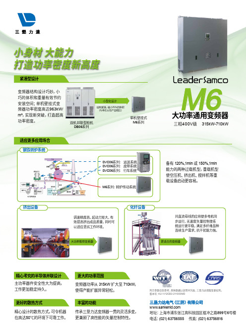
变频器结构设计巧妙,小巧的体积和重量有效节约安装空间;单机壁挂式变频器功率密度高达963kW/m³,实现新突破,打造超高功率密度。
化纤设备备有 120%,1min 或 150%,1min 能力的两种过载机型,重载机型使空压机、挤出机、搅拌机等重载设备启动更容易。
钢铁转炉系统SVC06系列: 运送系统SVC06系列: 皮带系统SVC06系列: 行车系统挤出设备精心考究的半导体并联设计丰富的功能更好的散热方式更大的功率范围变频器功率从 315kW 扩大至 710kW ,使得产能扩展异常轻松。
主功率器件安全性大为提高,工作更加稳定持久。
精心设计的散热方式,可令机器 在高达50℃的环境下可靠工作。
传承三垦力达变频器一贯的灵活多变,更兼顾了高性能的矢量控制特性。
M6系列:转炉传动系统更适合的变频器小型化设计结构紧凑,缩小70%的体积(与本社以往产品相比)大功率推荐变频器适应更多应用场合紧凑型设计M6※1 额定容量是输出电压为400V 时的容量。
※2 输入电压为AC400V 以上时,将根据输出功率降低额定电流。
※3 每10分钟允许过载1分钟。
※4 输出电压不能高于电源电压。
轻过载(P 模式)重过载(H模式)※5 根据带之流电抗器电源阻抗的不同而变化。
UA30CAD..TI超声分散数字输出传感器说明书
规格如有变更,恕不另行通知 (04.01.2017)1超声分散,数字输出型号 UA30CAD......TI• 圆柱形 M30 PBT 外壳• 感应距离:250-3500 mm • 电源:12 至 30 VDC• 输出:两个多功能开关输出。
PNP 或 NPN• 设置:正常开关或可调节磁滞• 重复性 0.2%• 波束角。
±6°• 防护措施:短路、反极性和过压• 防护等级 IP 67,Nema 4X • 2 m 线缆或 M12 插头产品说明感应范围为 250-3500 mm 的独立式多功能分散超声传感器。
2 个开关输出 - 可轻松为两种不同的输出模式设置并通过教导按钮调整 - 非常适合于各种容器中的液位控制任务。
坚固的整体式聚酯外壳为复杂的微处理器控制和数字过滤传感器电子元件提供理想的封装。
在实际距离测量中,此传感器的典型特色是 EMC 性能和优异的精度。
型号选择外壳 连接额定工作 数字输出 订购编号直径 距离 (S n ) NPN /PNP M30 插头 M12 250-3500 mm 2 x NPN UA 30 CAD 35 NP M1 TI M30 线缆250-3500 mm 2 x NPN UA 30 CAD 35 NP TI M30 插头 M12 250-3500 mm 2 x PNPUA 30 CAD 35 PP M1 TI M30线缆250-3500 mm2 x PNPUA 30 CAD 35 PP TI规格2规格如有变更,恕不另行通知 (04.01.2017)布线图UA30CAD..规格(续)检测范围尺寸规格如有变更,恕不另行通知 (04.01.2017)3UA30CAD..编程设置感测点 P1(最长距离)和 P2(最短距离)的常规设置与传感器类型或功能无关。
1) 将传感器安装到所选的应用中。
2) 将目标放在传感器前面的最大必要距离点 (P1),然后短暂按下教导按钮。
DPJ第二章(8535单片机系统结构)08年

5
AT90S8535特点 特点- § 2.1.1 AT90S8535特点-4
特别的MCU 8.特别的MCU 特点 •_上电复位电路 上电复位电路; 上电复位电路 •_具有计时功能、有独立振荡器的实时时钟(RTC); 具有计时功能、有独立振荡器的实时时钟(RTC) 具有计时功能 •_低功耗 三种节电模式: 空闲模式、省电模式和掉电模式 低功耗, 空闲模式、省电模式和掉电模式; 低功耗 •_内外部中断源 内外部中断源
15
§2.2.1 结构概述
•_ ALU算逻运算单元 ALU算逻运算单元
PC
•_32 个8 位通用寄存 器R0到R31。 最后6 个可以组成3 个 16 位用于间接寻址的 寄存器指针:X,Y,Z。 •_ 64 个I/O 寄存器 •_堆栈分布于SRAM , 堆栈指针SP为 16位, 可读写。
•_ R0到R31和 64 个I/O 寄存器 与SRAM内存一样分配有内存 地址,允许其象普通内存地址一样访问。 16
§2.3.1 内部在线可编程Flash(程序存储器) 内部在线可编程Flash( Flash §2.3.2 内部SRAM数据存储器 内部SRAM SRAM数据存储器 内部EEPROM EEPROM数据存储器 §2.3.3 内部EEPROM数据存储器 §2.3.4 §2.3.5 I/O 寄存器 内存映像
第二章
8535单片机系统结构 单片机系统结构
单片机AT90S8535 §2. 1 AVR单片机AT90S8535的总体结构 单片机AT90S8535的总体结构 8535单片机的中央处理器 单片机的中央处理器CPU §2. 2 8535单片机的中央处理器CPU §2. 3 §2. 4 8535单片机存储器组织 8535单片机存储器组织 AVR单片机系统复位 AVR单片机系统复位
松下 KX-FLB853CN传真机 说明书
非法复印 L 复印特定文稿属于非法行为。
在您所在国家复印特定文稿可能属于非法行 为。 这些犯罪行为可能导致罚款和/或监禁。 下面是一些在您所在国家可能属于非法的复 印行为示例。 - 货币 - 钞票和支票 - 银行和政府债券和有价证券 - 护照和身份证 - 未经所有者同意复印版权资料或商标 - 邮票和其它流通证券 此列表并不全面,我们对其完整性或准确性 不承担责任。 如有任何疑问,请与您的法律
重要信息
记录纸 L 对于尚未使用的纸,请原封不动地保持原来
的包装,并存放在凉爽干燥的地方。否则可 能会影响打印质量。 日常维护 L 用软布擦拭本机外层表面。切勿使用挥发 油、稀释剂或任何磨料粉。 移动本机 L 本机重量约为 18 kg。强烈建议由两个人搬动 本机。 L 移动本机时,抓住两侧的把手(1)。
1
1
18 kg
1 2
环境 L 应使本机远离产生电气干扰的装置,如荧光
灯和电机等。 L 应使本机避开灰尘、高温和振动。 L 勿将本机暴露在直接阳光照射下。 L 勿在本机上放置重物。 L 当您长时间不使用本机时,请从电源插座拔
出电源线。 L 将本机放置在远离加热器、厨房火炉等热源
的地方。请勿将本机放置在温度低于 10 ℃ 或 高于 32.5 ℃ 的房间。也不要放在潮湿的地下 室。
帮助按钮 2.5 帮助功能 ........................ 23
音量 2.6 调节音量 ........................ 24
初始编程 2.7 日期和时间 ...................... 24 2.8 您的识别信息 .................... 25 2.9 您的传真号码 .................... 27
FJN3303FBU;FJN3303FTA;中文规格书,Datasheet资料

* Pulse Test: Pulse Width = 5ms, Duty Cycle ≤ 10%Thermal Characteristics T A = 25°C unless otherwise notedOrdering InformationI CP Collector Current (Pulse) *3A I B Base Current (DC)0.75A I BP Base Current (Pulse) * 1.5A T J Junction Temperature 150°C T STGStorage Temperature range-65 to +150°CSymbolParameterValueUnitsP D Total Device Dissipation T C = 25°C T A = 25°C 1.1650W mW R θJC Thermal Resistance Junction-Case 48°C/W R θJAThermal Resistance Junction-Ambient190°C/WPart NumberMarking Info.PackagePacking MethodRemarksFJN3303FBU J3303F TO-92 (Straight)BULKGreen EMC FJN3303FTAJ3303FTO-92 (Form)AMMOGreen EMCDimensions in MillimetersDimensions in MillimetersThe following includes registered and unregistered trademarks and service marks, owned by Fairchild Semiconductor and/or its global subsidiaries, and is notAccuPower¥Auto-SPM¥Build it Now¥CorePLUS¥CorePOWER¥CROSSVOLT¥CTL™Current Transfer Logic™ EcoSPARK®EfficentMax™ EZSWITCH™*™*®Fairchild®Fairchild Semiconductor®FACT Quiet Series™ FACT®FAST®FastvCore¥FETBench¥FlashWriter®*FPS¥F-PFS¥FRFET®Global Power Resource SMGreen FPS¥Green FPS¥ e-Series¥G max™GTO¥IntelliMAX¥ISOPLANAR¥MegaBuck™MICROCOUPLER¥MicroFET¥MicroPak¥MillerDrive™MotionMax™Motion-SPM™OPTOLOGIC®OPTOPLANAR®®PDP SPM™Power-SPM¥PowerTrenchPowerXS™Programmable Active Droop¥QFET®QS¥Quiet Series¥RapidConfigure¥™Saving our world, 1mW/W/kW at a time™SmartMax™SMART START¥SPM®STEALTH™SuperFET¥SuperSOT¥-3SuperSOT¥-6SuperSOT¥-8SupreMOS™SyncFET™Sync-Lock™®*The Power FranchiseTinyBoost¥TinyBuck¥TinyCalc¥TinyLogic®TINYOPTO¥TinyPower¥TinyPWM¥TinyWire¥TriFault Detect¥TRUECURRENT¥*P SerDes¥UHC®Ultra FRFET¥UniFET¥VCX¥VisualMax¥XS™* Trademarks of System General Corporation, used under license by Fairchild Semiconductor.DISCLAIMERFAIRCHILD SEMICONDUCTOR RESERVES THE RIGHT TO MAKE CHANGES WITHOUT FURTHER NOTICE TO ANY PRODUCTS HEREIN TO IMPROVE RELIABILITY, FUNCTION, OR DESIGN. FAIRCHILD DOES NOT ASSUME ANY LIABILITY ARISING OUT OF THE APPLICATION OR USE OF ANY PRODUCT OR CIRCUIT DESCRIBED HEREIN; NEITHER DOES IT CONVEY ANY LICENSE UNDER ITS PATENT RIGHTS, NOR THE RIGHTS OF OTHERS. THESE SPECIFICATIONS DO NOT EXPAND THE TERMS OF FAIRCHILD’S WORLDWIDE TERMS AND CONDITIONS, SPECIFICALLY THE WARRANTY THEREIN, WHICH COVERS THESE PRODUCTS.LIFE SUPPORT POLICYFAIRCHILD’S PRODUCTS ARE NOT AUTHORIZED FOR USE AS CRITICAL COMPONENTS IN LIFE SUPPORT DEVICES OR SYSTEMS WITHOUT THE EXPRESS WRITTEN APPROVAL OF FAIRCHILD SEMICONDUCTOR CORPORATION.As used herein:1. Life support devices or systems are devices or systems which, (a) areintended for surgical implant into the body or (b) support or sustain life, and (c) whose failure to perform when properly used in accordance with instructions for use provided in the labeling, can be reasonably expected to result in a significant injury of the user. 2. A critical component in any component of a life support, device, orsystem whose failure to perform can be reasonably expected to cause the failure of the life support device or system, or to affect its safety or effectiveness.ANTI-COUNTERFEITING POLICYFairchild Semiconductor Corporation's Anti-Counterfeiting Policy. Fairchild's Anti-Counterfeiting Policy is also stated on our external website, , under Sales Support.Counterfeiting of semiconductor parts is a growing problem in the industry. All manufacturers of semiconductor products are experiencing counterfeiting of their parts. Customers who inadvertently purchase counterfeit parts experience many problems such as loss of brand reputation, substandard performance, failed applications, and increased cost of production and manufacturing delays. Fairchild is taking strong measures to protect ourselves and our customers from the proliferation of counterfeit parts. Fairchild strongly encourages customers to purchase Fairchild parts either directly from Fairchild or from Authorized Fairchild Distributors who are listed by country on our web page cited above. Products customers buy either from Fairchild directly or from Authorized Fairchild Distributors are genuine parts, have full traceability, meet Fairchild's quality standards for handling and storage and provide access to Fairchild's full range of up-to-date technical and product information. Fairchild and our Authorized Distributors will stand behind all warranties and will appropriately address any warranty issues that may arise. Fairchild will not provide any warranty coverage or other assistance for parts bought from Unauthorized Sources. Fairchild is committed to combat this global problem and encourage our customers to do their part in stopping this practice by buying direct or from authorized distributors.PRODUCT STATUS DEFINITIONSDefinition of TermsDatasheet Identification Product Status Definition分销商库存信息:FAIRCHILDFJN3303FBU FJN3303FTA。
853控制柜调试指导书
为099-100。
6.6.5. 再将载重量增加至额定载荷就可达到超载报警。
称重装置的插头端子对照表见下面表格。
6.7、舒适感调整一般情况下调整3319中的加速度、减速度及其jerk0-jerk3进行调整。
根据现场的实际情况而定,一般不调。
6.8、试外招和消防a用万用表量H4插键是否有短路,正常后插好,拨好地址码。
外召地址从21开始,一个地址一层,以此类推,按下按钮能呼到指定楼层,完毕。
b按下消防开关,电梯能返回指定楼层,且轿厢显示紧急退出,轿门一直打开,则正常。
以上结束后电梯上下反复运行几次,正常则调试完毕。
七、故障排除3.9编码器定位出厂时主机已经与控制柜进行配对试验,定位角度已经存在变频器中,如果发现主机运行异常或驱动器内参数与主机实际参数不符,则需要重新定位。
断电,将钢丝绳拨离曳引轮,短接SW-A1和BY-A1到AC110V,上电使接触器吸合,设置好驱动器参数和电机铭牌参数,将RUN SOURCE设成“0”,RUN ENABLE设成“0”。
用服务器插入SVT2,并按“M-3-3-2”并按“ENTER”键进行确认主机定位,注意:定位过程中主机将旋转(在此过程中要确认抱闸已经打开);等待服务器出现“Learning finished”表示定位完成;注意:如果电机相位更换,则需要进行重新定位,或更改成原来相位;3.10点动运行时,BY、SW不能正常吸合检查安全信号输入、输出(IO)信号是否正常,如不正常应根据原理图检查线路;如信号正常,请检查驱动器参数,参见驱动器参数表。
3.11点动运行时,接触器、抱闸继电器及抱闸正常打开,电机不转,电流很大“Drive Overload”。
可能是变频器到主机三相相序不对,应按照正确方法连接主机动力线,参见“2.6 动力线检查”。
3.12自学习运行到顶层后,电梯不能正常运行检查run enable值,应该设置成“1”,另外请检查井道信号是否正常。
3.13常见驱动器故障3.13.1驱动器“Over current”信息电流过大。
M30 CA30CLN25BP CA30CLN25BPM1 M32 CA32CLN25BP 电容式液

M30 CA30CLN25BP CA30CLN25BPM1 M32CA32CLN25BP产品说明用于塑料和橡胶的电容式液位传感器热塑性聚酯外壳型号 CA ,M30,M32,DC ,自我教导式• 设计用于塑料和橡胶应用• 用于干燥批量材料的检测• 具有 TRIPLESHIELD ™ 传感器保护• 通过导线进行感应距离的自我教导或远程调整• 感应表面耐受最高 120°C • 自动检测 NPN 或 PNP 负载• 借助远程功能实现的可选择断或续开关• 保护:短路、瞬态和电极反接• 湿度补偿• 5 年保修型号选择专门针对塑料和橡胶应用中的液位检测而设计与优化的电容式液位检测器。
首次通电时,传感器将自动适应您的应用。
可通过远程教导功能方便地更改调整。
传感器正面可承受最高 120°C 。
具有可选择断 (NO) 或续 (NC) 开关的 3 线 DC 输出。
带 2 m PVC 线缆或 M12 插头的灰色聚酯外壳(仅限 M30)。
规格TR IP L E S H IE L D ™外壳直径订购编号电缆订购编号插头CA ,M30,M32,DC ,自我教导式接线图安装首次校准按照上面的接线图安装传感器并装电线。
记得将白线(第 4 根线)与 (+) 电源相连。
首次为传感器通电时,传感器将自动适应环境并自行计算最佳灵敏度 - 无论要检测何种塑料材料。
只要白线与 (+) 电源相连,传感器就将锁定并处于运行模式。
锁定传感器设置无需任何其他调整。
只要白线与 (+) 电源相连,传感器的设置就处于锁定状态,并且在其他关机/开机期间不会更改。
传感器重新校准如果需要,可以激活新的自我教导,方法是将白线从 (+) 电源断开,然后再次将其与 (+) 电源相连。
您现在已激活新的自我教导,传感器现在将重新校准并根据应用来计算新的灵敏度。
请确保应用为空 - 没有要检测的物体。
每次将白线从 (+) 电源断开时,自我教导功能都将初始化并在白线再次与 (+)电源相连时进行远程教导可以“教导”背景或物体,例如通过具有正常教导功能的 CAxxCLL 传感器。
卡萨帝家用直流变频空调 CAS353WAA(81)U1说明书
智能家电操控智慧场景定制智家商城购物家电报装报修使用说明书使用前请仔细阅读本说明书本公司保留说明书解释权产品外观请以实物为准阅后请与发票一并妥善保存如遇产品技术或软件升级,恕不另行通知本产品只适合在中国大陆销售和使用CAS353WAA(81)U1(SKFR-35GW/03WAA81KU1)CAS353WBA(81)U1(SKFR-35GW/03WBA81KU1)CAS353WFA(81)U1(SKFR-35GW/03WFA81KU1)WAAWBAWFA卡萨帝为了精确实现您的格调生活,对其家族每一类产品都赋予了专属的境界理念。
本产品为您带来的是冷暖舒适。
12关于本产品的安全注意事项.........................................................3本产品的安装事项 (5)参数要求.............................................................................5随机附件 (5).................................................6室内外机安装图...................................................................6安装(按照室内机组安装图进行安装).................................7管路系统图...........................................................................7安装检查及试运转................................................................7室内机管路布置.................................................8接线方法..............................................................................8室内外机接线..................................................................排空方法(R32)10本产品的外观及部件介绍. (11)室内机................................................................................11室内机显示面板.................................................................11室外机...............................................................................11遥控器(外侧)...................................................................12本产品的主要功能介绍. (14)1.时钟校准............................................................................................................................................142.定时功能143.自动化空气调节(制冷、制热、辅热、除湿、送风)....164.设置温度5.设定风区、风速、风向以及健康气流自清洁功能6.语音以及Wi-Fi功能177.温度显示及关闭/开启显示面板219.停电补偿功能2210.静眠功能.....................................................................1911.20本产品的日常保养与维护24空气过滤网的安装24清洗机器............................................................24换季收存24有疑问?先看这儿!26(若对空调有疑问,请先按本章内容检查处理。
RightSight M30 光电感应器系列产品说明书
Technical DataOriginal InstructionsRightSight M30Catalog Numbers 42AF-P2MAB1-F4, 42AF-P2MAB1-D4, 42AF-P2RHB1-G4, 42AF-E1EZB1-F4, 42AF-E1EZB1-D4, 42AF-R1MAB1-D4,42AF-R1MAB1-F4, 42AF-R1RHB1-G4, 42AF-E1UZB1-G4, 42AF-P2CHB1-A2, 42AF-R1CHB1-A2, 42AF-E1UZB1-A2, 42AF-P2SHB1-G4,42AF-R1SHB1-G4, 42AF-P2CHB1-M5, 42AF-R1CHB1-M5, 42AF-E1UZB1-M4Summary of ChangesThis publication contains the following new or updated information.This list includes substantive updates only and is not intended toreflect all changes.DescriptionThe RightSight™ M30 family of photoelectric sensors offers high-performance general-purpose sensing in a robust flexible package.They are designed for applications where simplified installation andmaintenance are required.Designed to withstand the rigors of material handling andpackaging environments, the RightSight M30 standard models canwithstand IP69K high-pressure washdowns.This family also offers a background reflection/foregroundsuppression sensing mode that allows you to use the surface of abackground (for example, a conveyor) as a reflector. The detectionof a target occurs once an object blocks the visual path betweenthe sensor and the background (for example, conveyor).Available Models•Polarized retroreflective•Transmitted beam•Background suppression•Background reflectionStatus IndicatorsTopic PageDescription1Status Indicators1Features2Specifications2Product Selection3Sensor User Interface4Wiring4Approximate Dimensions5Typical Response Curves5Accessories6Topic PageUpdated Description1Updated Available Models list1Updated Features2Updated Product Selection table and Connection OptionsImportant table that follows3Updated Figure2, Figure3, Figure4, and Figure9 titles 4 and 5Updated Figure125Orange IndicatorGreen Indicator2Rockwell Automation Publication 42AF-TD001B-EN-P - June 2020RightSight M30 Technical DataFeatures•Maximum sensing distance-Background suppression without physicaladjustments (a): 400 mm (15.7 in.) and 600 mm (23.6 in.)-Background suppression with push button teach (a): 1.2 m (3.94 ft)-Background reflection with push button teach (a): 800 mm (31.5 in.)-Polarized retroreflective:10 m (32.8 ft) with 92-125 reflector -Transmitted beam:80 m (262.5 ft)•High powered light source for ease of alignment•360° highly visible user interface helps operators verify the proper operation, regardless of the sensor installation location•Background suppression performance helps minimize false detections due to highly reflective backgrounds•Dual Auto PNP/NPN helps streamline inventory by reducing the number of catalog numbers to stock•Push button lock helps prevent unauthorized operators from changing the sensor settings•Embedded IO-Link 1.1 communications protocol•Adjustable sensing ranges and response time via IO-Link provides additional flexibility to detect targets at longer or shorter distances depending on the application requirements.•IP67 and IP69K rated enclosure.Specifications(a)All models can be taught to detect targets up to 4 m (13.1 ft.) when using IO-Link to adjustthe response timeAttribute ValueCertifications c-UL-us and CE Marked for all applicable directivesVibration 10…55 Hz, 1 mm (0.04 in.) amplitude, meets, or exceeds 60947-5-2Shock30 g (1.1 oz) with 1 ms pulse duration per IEC 60947-5-2Ambient light immunity •Direct Illumination: 20,000 lux•Indirect Illumination: 5000 lux•Sunlight immunity; 108,000 lux User Interface Status indicators Green and orange light-emitting diodes (LED)Electrical Adjustments No physical adjustment. IO-Link adjustable Operating voltage •DC models: 10...30V DC, IO-Link: 18 (30V)•AC/DC models: AC: 24…250V AC/DC: 20…250V DC Current consumption 35 mA maxSensor protection DC: Reverse polarity and short circuit; AC/DC: Reverse polarity Discrete Output Response time •DC: 1 ms•AC/DC: 15 ms max Output type •DC: Dual Auto PNP or NPN •AC/DC: EM RelayLoad current •DC: 100 mA max•AC/DC SPDT: 10…30V DC: 3 A; 31…125V DC: 200 mA;24…250V AC: 3 AIO-LinkCommunications mode COM2Cycle time, min 2 ms Process data bit length 32 bits (4 bytes)Specifications 1.1Mechanical Housing material PBT Lens material PMMA Cover material Polysulfone Reliability DataTransmitted Beam and Polarized Retroreflective AC/DC MTTFd (hours)6548788.474T10d78.76Transmitted Beam and Polarized Retroreflective DC MTTFd (hours)9310986.965T10d111.9875Transmitted Beam Emitter AC/DC MTTFd (hours)24271844.66T10d291.9285467Transmitted Beam Emitter DC MTTFd (hours)24271844.66T10d 291.9285467Environmental Enclosure type ratingIP67 and IP69K per ISO 20653 rated enclosureOperating temperature -40…+70 °C (31…158 °F) (1)(1)The sensing range for all sensing modes can be reduced up to 20% when operatedbetween -40…-25 °C (-40…-13 °F).Connection type • 2 m (6.5 ft) cable •4-pin Integral M12 QD•4-pin M12 QD on a 150 mm (5.9 in.) pigtail•4-pin mini QD on 150 mm (5.9 in.) pigtail •5-pin mini QD on 150 mm (5.9 in.) pigtailRockwell Automation Publication 42AF-TD001B-EN-P - June 20203RightSight M30 Technical DataProduct SelectionSee https:///Sensors-Switches/Photoelectric-Sensors for additional details about the operation of the RightSight M30 in IO-Link mode.Sensing Mode Operating Voltage Light SourceSensing DistanceSensitivity Adjustment Output Function Output Type Cat. No.Background Suppression10...30V DC InfraredDefault setting:10...400 mm (0...15.7 in.)No physical adjustment. IO-Link teach: 4 m (13.1 ft) (1)(1)Sensor response time can be changed up to 75 ms to achieve distance of up to 4 m (13.1 ft). A higher distance between target and high reflectivity background may be needed whenoperating the sensors at distances greater than 2 m (6.6 ft).Light and dark operate Dual autoPNP or NPN42AF-B1MAB1-D4Default setting:10...600 mm (0...23.6 in.)No physical adjustment. IO-Link teach: 4 m (13.1 ft) (1)42AF-B1MAB2-D4Default setting:10...1.2 m (0...3.9 ft)Push button teach: 3 m (9.8 ft) IO-Link teach: 4 m (13.1 ft) (1)42AF-B1MAC1-D4Background Reflection10...30V DC Infrared0...800 mm (0...31.5 in.)Push button teach: 3 m (9.8 ft) IO-Link teach: 4 m (13.1 ft) (1)Light and dark operate Dual auto PNP or NPN 42AF-N1MAC1-D4Polarized Retroreflective10...30V DCVisible red0.025...10 m (0.03...33 ft)with 92-125 reflector No adjustment (IO-Link adjustable)Light and dark operate Dual auto PNP or NPN42AF-P2MAB1-D420...250V DC 24...250V AC No adjustment Light operate SPDT EM relay 42AF-P2RHB1-G4Dark operate 42AF-P2SHB1-G4Light and dark operate42AF-P2CHB1-A2Transmitted Beam10...30V DC Infrared0...80 m (0...262 ft)No adjustment (IO-Link adjustable)Transmitted beam emitter —42AF-E1EZB1-D420...250V DC 24...250V AC42AF-E1UZB1-G410...30V DC No adjustmentLight and dark operate Dual auto PNP or NPN 42AF-R1MAB1-D420...250V DC 24...250V ACLight operate SPDT EM relay42AF-R1RHB1-G4Dark operate 42AF-R1SHB1-G4Light and dark operate42AF-R1CHB1-A2IMPORTANTConnection Options (1): The following suffixes describe the available connection options:•D4: Describes an integral 4-pin DC micro (M12) quick-disconnect for DC models.•G4: Describes a 4-pin AC micro (M12) quick-disconnect on a 150 mm (6 in.) length pigtail on AC/DC models.•F4: Describes a 4-pin DC micro (M12) quick-disconnect on a 150 mm (6 in.) length pigtail on DC models.•A2: Describes a 2 m (6.6 ft) PVC cable.•M4: Describes a 4-pin mini quick-disconnect on a 150 mm (6 in.) length pigtail. Transmitted beam emitter only.•M5: Describes a 5-pin mini quick-disconnect on a 150 mm (6 in.) length pigtail on AC/DC models. Polarized retroreflective and transmitted beam receivers only.(1)Additional connection options may be available. See the ProposalWorks™ tool for available options by sensing mode.Table 1 - Standard I/O (Auto PNP/NPN) Operating Mode IndicationColorStatus Description GreenOFF Power is off ON Power is onFlash (6 Hz)Unstable light: 0.8 X <margin<1.5X Flash (1.4 Hz)Output short circuit protection active OrangeOFF Output de-energized ONOutput energizedTable 2 - IO-Link Operating Mode IndicationColor Status Description Green OFF Power is off Flash (1 Hz)Power is onOrangeOFF Output de-energized ONOutput energized4Rockwell Automation Publication 42AF-TD001B-EN-P - June 2020RightSight M30 Technical DataSensor User InterfaceThe green status indicator can also serve as a setup alignment aid. As the sensor is adjusted, • A flashing green indicator shows that the sensor has detected a margin of 0.8 X• A flashing green indicator and steady orange output indicator shows a margin greater than 1•Steady green and orange indicators show a margin greater than 1.5. This status means that the sensor is receiving at least 1.5 times the signal strength back from the target that is required to trigger an output signal.In general, it is desirable to have a higher margin to help overcome any deteriorating environmental conditions (dust build-up on the sensor lens). When aligning the sensor, the optimum performance can be obtained if this margin indicator is illuminated with the target in place.Table 3 provides indicator status in the RUN mode, during operation. The sensor is always in run mode except when being taught.WiringThe quick-disconnect connector is shown in Figure 1. The pin numbers correspond to the male connectors on the sensor.Figure 1 - PinoutsDC ModelsFigure 2 - Polarized Retroreflective(42AF-P2MAB1-F4 and 42AF-P2MAB1-D4)Light Operate and Dark Operate (Auto PNP or NPN)Figure 3 - Transmitted Beam Receiver (42AF-R1MAB1-F4 and 42AF-R1MAB1-D4)Light Operate and Dark Operate (Auto PNP or NPN)Figure 4 - Transmitted Beam Emitter (42AF-E1EZB1-F4 and 42AF-E1EZB1-D4)Table 3 - Connection TypesDescriptionCat. No. Suffix2 m (6.56 ft) cable-A24-pin DC micro (M12) QD on 150 mm (6 in.) pigtail -F4Integral 4-pin DC micro (M12) QD-D44-pin AC micro on 150 mm (6 in.) pigtail -G44-pin mini QD on 150 mm (6 in.) pigtail -M45-pin mini QD on 150 mm (6 in.) pigtail-M5Item DescriptionLED Disable For normal operation, the white wire needs no connection.To disable the light source, connect the white wire to +V.Frequency SelectFor normal operation, the white wire needs no connection.To change the emitter operating frequency, connect the black wire to +V. This feature is supported in future firmware revisions of the Transmitted Beam Receiver.IMPORTANTFor transmitted beam emitter only:Do not connect pin 2 and pin 4 for normaloperation. Unless a change in frequency is required when working with a receiver, these two pins remain unconnected when wiring the transmitted beam emitter sensor to anArmorBlock® I/O module.4-pin Micro (M12)Brown (1)Blue (3)Black (4)White (2)+V-VLight Operate (Auto PNP/NPN)Dark Operate (Auto PNP/NPN)Brown (1)Blue (3)Black (4)White (2)+V-VLight Operate (Auto PNP/NPN)Dark Operate (Auto PNP/NPN)Brown (1)Blue (3)Black (4)White (2)+V-VFrequency Select LED DisabledRockwell Automation Publication 42AF-TD001B-EN-P - June 20205RightSight M30 Technical DataAC/DC ModelsFigure 5 - Polarized Retroreflective and Transmitted Beam Emitter Light Operate (42AF-P2RHB1-G4 and 42AF-R1RHB1-G4)Figure 6 - Dark Operate(42AF-P2SHB1-G4 and 42AF-R1SHB1-G4)Figure 7 - Polarized Retroreflective and Transmitted Beam (42AF-P2CHB1-A2 and 42AF-R1CHB1-A2)Figure 8 - Polarized Retroreflective and Transmitted Beam (42AF-P2CHB1-M5 and 42AF-R1CHB1-M5)Figure 9 - Transmitted Beam Emitter (42AF-E1UZB1-A2 and 42AF-E1UZB1-G4)Approximate DimensionsFigure 10 - Integral M12 Connector [mm (in.)]Figure 11 - M12 Pigtail and Cable Models [mm (in.)]Typical Response CurvesFigure 12 - Visible Red Polarized Retroreflective — 10 m (32.81ft) Margin CurveFigure 13 - Visible Red Polarized Retroreflective — 10 m (32.81ft) Beam PatternTable 4 - UL508 Overcurrent ProtectionConductor Size Ampere Rating of the Overcurrent Protection, MaxAWG mm 2200.525220.323240.202260.131280.080.8300.050.5Red w/Black (1)Green (3)Red (4)Red w/White (2)(-V) L2(No Connection)Light Operate (+V) L1Red w/Black (1)Green (3)Red (4)Red w/White (2)(-V) L2(No Connection)Light Operate (+V) L1(+)˜(-)˜(+)˜(-) ˜Red w/Black (1)Not Used (3)Not Used (4)Red w/White (2)(-V) L2(+V) L1Sensing Distance [m (ft)]O p e r a t i n g M a r g i n 0.01(0.03)0.1(0.33)1(3.28)10(32.81)01020304050607080(13.12)(19.68)(26.25)(32.81)(39.37)Distance [m (ft)]D i s t a n c e [c m ](6.56)6Rockwell Automation Publication 42AF-TD001B-EN-P - June 2020RightSight M30 Technical DataFigure 14 - Infrared Transmitted Beam Emitter — 80 m (262.5ft) Margin CurveFigure 15 - Infrared Transmitted Beam Emitter — 80 m (262.5ft) Beam PatternAccessoriesFigure 16 - 30 mm (1.2 in.) Right Angle Mounting BracketFigure 17 - 18 mm (0.7 in.) Swivel/Tilt Mounting BracketCat. No. 60-2421Cat. No. 60-2439IMPORTANTFor polarized retroreflective sensors only: For optimal detection performance, when highly reflective targets pass between the emitter and the reflector, we recommend that you always install the rubber washer that is provided with the polarized sensor.(0.33)(3.28)(32.81)(328.08)Sensing Distance [m (ft)]O p e r a t i n g M a r g in(13.12)(19.68)(26.25)(32.81)(39.37)Distance [m (ft)]D i s t a n c e [c m ](6.56)Cat. No. 60-2649Cat. No. 60-2681DescriptionCat. No.4-pin DC micro, 2 m (6.5 ft) cordset 889D-F4AC-218 mm (0.7 in.) straight bracket 60-265618 mm (0.7 in.) right angle bracket60-265730 mm (1.2 in.) stainless steel mounting bracket 60-242130 mm (1.2 in.) swivel/tilt bracket 60-243918 mm (0.7 in.) swivel/tilt bracket60-2649Extended 18 mm (0.7 in.) swivel/tilt bracket 60-268176 mm (3 in.) diameter reflector 92-3947 mm (1.85 in.) diameter reflector 92-4784 mm (3.3 in.) diameter reflector92-12518 mm (0.7 in.) base mount, U-shaped protective bracket 60-BAF-US 18 mm (0.7 in.) base mount bracket, stainless steel 60-BAF-BM 30 mm (1.2 in.) nose mount bracket, stainless steel60-BAF-SM Aperture, 5 x 17 mm (0.2 x 0.67 in.) vertical slot, stainless steel 60-AAF1-VS Aperture, 5 x 12 mm (0.2 x 0.47 in.) horizontal slot, stainless steel 60-AAF1-HS Aperture, 2.5 x 12 mm (0.1 x 0.47 in.) horizontal slot, stainless steel 60-AAF2-HS Aperture, 5 mm (0.2 in.) diameter, stainless steel 60-AAF1-DS Aperture, 2.5 mm (0.1 in.) diameter, stainless steel 60-AAF2-DS U-shaped protective bracket60-BAF-US 18 mm (0.7 in.) base mount bracket, stainless steel 60-BAF-BM 30 mm (1.2 in.) nose mount bracket, stainless steel60-BAF-SM Aperture, 5 x 17 mm (0.2 x 0.67 in.) vertical slot, stainless steel 60-AAF1-VS Aperture, 5 x 12 mm (0.2 x 0.47 in.) horizontal slot, stainless steel 60-AAF1-HS Aperture, 2.5 x 12 mm (0.1 x 0.47 in.) horizontal slot, stainless steel 60-AAF2-HS Aperture, 5 mm (0.2 in.) diameter, stainless steel 60-AAF1-DS Aperture, 2.5 mm (0.1 in.) diameter, stainless steel60-AAF2-DSRockwell Automation Publication 42AF-TD001B-EN-P - June 20207RightSight M30 Technical DataFigure 18 - AperturesFigure 19 - Cat. No. 60-BAF-US 18 mm (0.7 in.) Mounting BracketFigure 20 - Cat. No. 60-BAF-SM 30 mm (1.2 in.) Bracket SideFigure 21 - Cat. No. 60-BAF-BM 18 mm (0.7 in.) Bracket BackCat. No. 60-AAF1-VS 5x17 mm (0.2x0.67 in.)Vertical SlotCat. No. 60-AAF1-HS 5x12 mm (0.2x0.47 in.) Horizontal SlotCat. No. 60-AAF2-HS 2.5x12 mm (0.1x0.47 in.)Horizontal SlotCat. No. 60-AAF1-DS 5 mm (0.2 in.) DiameterCat. No. 60-AAF2-DS 2.5 mm (0.1 in.)DiameterØØ4.5018.49 (0.73)(0.33)12.7 (0.50)33.02 (1.30)6.98(0.27)2 x 1.84 (0.07)9.73(0.38)2 x Ø 4.5 (0.18)12.7(0.50)4 x 4.57(0.18)6.35(0.25)22.2(0.87)22.86 (0.90)Ø 30.15 (1.19)3.17(0.12) Ref19.05 (0.75)44.45 ± 0.25(1.75 ± 0.01)0.79(0.03) Ref90°2 x 82°R 2.29(0.09)2 x 0.77 (0.03)45.72 (1.80)2 x Ø 3.83 (0.15)2 x 1.75 (0.06)17.78(0.70)30.48 (1.20)3.17(0.12) Ref2 x 0.79(0.31)15.16(0.60)90°2 x 82°R 2.29(0.09)Ø 18.49(0.73)8.89 (0.35)9.27 (0.36)6.98(0.27)8.25(0.32)8.89(0.35)19.05 (0.75)4 x R 4.57 (0.18)35.56 (1.40)30.48(1.20)0.79(0.03) RefPublication 42AF-TD001B-EN-P - June 2020Supersedes Publication 42AF-TD001A-EN-P - January 2019Copyright © 2020 Rockwell Automation, Inc. All rights reserved. Printed in the U.S.A.Rockwell Automation SupportUse these resources to access support information.Documentation FeedbackYour comments help us serve your documentation needs better. If you have any suggestions on how to improve our content, complete the form at rok.auto/docfeedback .Waste Electrical and Electronic Equipment (WEEE)Technical Support Center Find help with how-to videos, FAQs, chat, user forums, and product notification updates.rok.auto/support KnowledgebaseAccess Knowledgebase articles.rok.auto/knowledgebase Local Technical Support Phone Numbers Locate the telephone number for your country.rok.auto/phonesupport Literature LibraryFind installation instructions, manuals, brochures, and technical data publications.rok.auto/literature Product Compatibility and Download Center (PCDC)Get help determining how products interact, check features and capabilities, and find associated firmware.rok.auto/pcdcAt the end of life, this equipment should be collected separately from any unsorted municipal waste.Rockwell Automation maintains current product environmental information on its website at rok.auto/pec .Allen-Bradley, ArmorBlock, expanding human possibility, ProposalWorks, RightSight, Rockwell Automation, and Rockwell Software are trademarks of Rockwell Automation, Inc.Trademarks not belonging to Rockwell Automation are property of their respective companies.Rockwell Otomasyon Ticaret A.Ş. Kar Plaza İş Merkezi E Blok Kat:6 34752, İçerenkÖy, İstanbul, Tel: +90 (216) 5698400 EEE YÖnetmeliğine Uygundur。
Eaton JGS405032G型号电子液体电路断路器说明书

Eaton JGS405032GEaton Series G electronic molded case circuit breaker, JG-frame, JG, Digitrip 310 RMS, Electronic LSI trip, Four-pole, 50A, 600 Vac, 250 Vdc, 85 kAIC at 240 Vac, 35 kAIC at 480 Vac, 18 kAIC at 600 Vac, Line and load, 50/60 HzGeneral specificationsEaton Series G electronic molded case circuit breakerJGS405032G 7821169997053.44 in 7 in5.34 in 16 lb Eaton Selling Policy 25-000, one (1) year from the date of installation of theProduct or eighteen (18) months from thedate of shipment of the Product,whichever occurs first.CE Marked IEC RatedCSA CertifiedUL ListedProduct NameCatalog NumberUPCProduct Length/Depth Product Height Product Width Product Weight WarrantyCompliancesCertificationsSeries G85 kAIC at 240 Vac 18 kAIC at 600 Vac 35 kAIC at 480 VacComplete breakerJGJG50/60 HzComplete breakerLine and load600 Vac, 250 Vdc50 AElectronic LSIFour-pole Application of Tap Rules to Molded Case Breaker Terminals Application of Multi-Wire Terminals for Molded Case Circuit BreakersMulti-wire lugs product aidCircuit breaker motor operators product aidStrandAble terminals product aidPower metering and monitoring with Modbus RTU product aidMotor protection circuit breakers product aidHigh performance operating handles for Series G circuit breakers product aidComprehensive circuit protection for control panel applicationsPlug-in adapters for molded case circuit breakers product aidSeries G MCCB quick selectorMolded case circuit breakers providing higher levels of selective coordination product aidCurrent limiting molded case circuit breaker module for series G, JG and CLCurrent limiting molded case circuit breaker module product aidJ-Frame 310+ and L-Frame 310+ Molded-case circuit breakers Breaker service centersEaton's Volume 4—Circuit ProtectionMolded case circuit breakers catalogJG-frame Molded Case Circuit Breaker DrawingInstallation Instructions for Series G J-Frame Circuit BreakersNG and ND-Frame molded case circuit breakersSeries G, J-frame Time Current CurveEaton Specification Sheet - JGS405032GMOEM MCCB product selection guideSeriesInterrupt ratingTypeFrameCircuit breaker type Frequency ratingCircuit breaker frame type TerminalsVoltage rating Amperage RatingTrip TypeNumber of poles Application notesBrochuresCatalogsDrawingsInstallation instructions Specifications and datasheetsEaton Corporation plc Eaton House30 Pembroke Road Dublin 4, Ireland © 2023 Eaton. All Rights Reserved. Eaton is a registered trademark.All other trademarks areproperty of their respectiveowners./socialmedia。
- 1、下载文档前请自行甄别文档内容的完整性,平台不提供额外的编辑、内容补充、找答案等附加服务。
- 2、"仅部分预览"的文档,不可在线预览部分如存在完整性等问题,可反馈申请退款(可完整预览的文档不适用该条件!)。
- 3、如文档侵犯您的权益,请联系客服反馈,我们会尽快为您处理(人工客服工作时间:9:00-18:30)。
Automobiles, audio, cameras, office equipment, communications equipment, portable equipment, etc.
Rev. 1.21 Jul. 01, 2005 Page 1 of 87
元器件交易网
22 mA (VCC1=VCC2=3.3 V,
10µA (VCC1=VCC2=5 V,
f(BCLK)=24 MHz)
f(BCLK)=32 kHz, in wait mode)
10µA (VCC1=VCC2=5 V,
f(BCLK)=32 kHz, in wait mode)
3.3 V ± 0.3 V or 5.0 V ± 0.5 V
(f(BCLK)=32 MHz)
(f(BCLK)=32 MHz)(3)
VCC1=3.0 V to 5.5 V, VCC2=3.0 V to VCC1
(f(BCLK)=24 MHz)
28 mA (VCC1=VCC2=5 V,
28 mA (VCC1=VCC2=5 V,
f(BCLK)=32 MHz)
f(BCLK)=32 MHz)
Time measurement function or Waveform generating function:
16 bits x 8 channels
Communication function (Clock synchronous serial I/O, Clock asyn-
chronous serial I/O, HDLC data processing)
5.0 V ± 0.5 V
100 times (all space) –20 to 85oC
–40 to 85oC (T version)
–40 to 85oC (optional)
144-pin plastic molded LQFP
NOTES: 1. IEBus is a trademark of NEC Electronics Corporation. 2. I2C bus is a trademark of Koninklijke Philips Electronics N. V. 3. The supply voltage of M32C/85T (High-reliability version) must be VCC1=VCC2. 4. The cold start-up/warm start-up determine function is available only at the user&#ing Mode
Single-chip mode, Memory expansion Single-chip mode
mode and Microprocessor mode
Address Space
16 Mbytes
Memory Capacity
See Table 1.3
Peripheral I/O Port
Characteristic
Performance
M32C/85
M32C/85T
CPU Basic Instructions
108 instructions
Minimum Instruction Execution Time 31.3 ns
31.3 ns
(f(BCLK)=32 MHz, VCC1=4.2 V to 5.5 V) (f(BCLK)=32 MHz, VCC1=4.2 V to 5.5 V)
Table 1.1 M32C/85 Group (M32C/85, M32C/85T) Performance (144-Pin Package)
Characteristic
M32C/85
Performance
M32C/85T
CPU Basic Instructions
108 instructions
Oscillation Stop Detect Function Voltage Detection Circuit Electrical Supply Voltage Characteristics Power Consumption
Flash Program/Erase Supply Voltage Memory Program and Erase Endurance Operating Ambient Temperature Package
123 I/O pins and 1 input pin
Function Multifunction Timer
Timer A: 16 bits x 5 channels, Timer B: 16 bits x 6 channels
Three-phase motor control circuit
Intelligent I/O
元器件交易网
M32C/85 Group (M32C/85, M32C/85T)
SINGLE-CHIP 16/32-BIT CMOS MICROCOMPUTER
REJ03B0046-0121 Rev.1.21
Jul. 01, 2005
1. Overview
The M32C/85 group (M32C/85, M32C/85T) microcomputer is a single-chip control unit that utilizes highperformance silicon gate CMOS technology with the M32C/80 series CPU core. The M32C/85 group (M32C/85, M32C/85T) is available in 144-pin and 100-pin plastic molded LQFP/QFP packages. With a 16-Mbyte address space, this microcomputer combines advanced instruction manipulation capabilities to process complex instructions by less bytes and execute instructions at higher speed. It includes a multiplier and DMAC adequate for office automation, communication devices and industrial equipments, and other high-speed processing applications.
All options are on a request basis.
Rev. 1.21 Jul. 01, 2005 Page 2 of 87
元器件交易网
M32C/85 Group (M32C/85, M32C/85T)
1. Overview
Table 1.2 M32C/85 Group (M32C/85, M32C/85T) Performance (100-Pin Package)
A/D Converter
10-bit A/D converter: 1 circuit, 34 channels
D/A Converter
8 bits x 2 channels
DMAC
4 channels
DMAC II CRC Calculation Circuit X/Y Converter Watchdog Timer Interrupt Clock Generation Circuit
16 Mbytes
Memory Capacity
See Table 1.3
Peripheral I/O Port
87 I/O pins and 1 input pin
Function Multifunction Timer
Timer A: 16 bits x 5 channels, Timer B: 16 bits x 6 channels
Three-phase motor control circuit
Intelligent I/O
Time measurement function or Waveform generating function:
16 bits x 8 channels
Communication function (Clock synchronous serial I/O, Clock asyn-
Can be activated by all peripheral function interrupt sources
Immediate transfer, Calculation transfer and Chain transfer functions
CRC-CCITT
16 bits x 16 bits
15 bits x 1 channel (with prescaler)
39 internal and 8 external sources, 5 software sources
Interrupt priority level: 7
4 circuits
Main clock oscillation circuit(*), Sub clock oscillation circuit(*), On-chip oscillator, PLL frequency synthesizer (*)Equipped with a built-in feedback resistor. Ceramic resonator or
M32C/85 Group (M32C/85, M32C/85T)
