MAX9286介绍
MAX9632-MAX9633低噪音

MAX9632/MAX9633 低噪音
Maxim 的新轨至轨运算放大器提供高电压性能在低频率,精确的规格,高收益,能够在工业应用精密的信号调理。
位于美国加州Sunnyvale,2010 年11 月9 日,MAXIM 集成产品公司(NASDAQ:MXIM)推出MAX9632/MAX9633 的36V,低噪音,低失真精密运算放大器。
在Maxim 的高电压,精密运算放大器新系列的第一个器件,MAX9632/MAX9633 的设计采用了一个专有的高速互补BiCMOS 工艺
(CB5HV)。
这个高电压模拟工艺优化交流优秀的动态性能,超低噪声,工作电压范围宽,低漂移信号调理。
MAX9632/MAX9633 目标的工业数据采集系统的精度要求在低频信号调理。
在MAX9632 是单运放具有超低输入电压噪声密度0.94nV /,低偏移的125μV(最大值),和偏移量温度系数的0.5μV/° C(最大)。
在MAX9633 是一款双用的3nV 输入电压噪声密度运算放大器/,对200μ偏移(最大)一,和偏移量温度系数的0.9μV/° C(最大)。
这两款器件提供高规格的信号保真度和总谐波失真调节优于-一三六分贝,能够在专业音响设备和高端测试和仪器仪表应用。
增益带宽积(GBWP)是典型的MAX9632 和MAX9633 27MHz 时为55MHz 的。
这可用带宽,慷慨的4.5V 至36V 工作电压范围,典型的三点九毫安(MAX9632)电流消耗相结合,。
蜚声功放说明书

5. 安装孔 用于安装到机柜时固定用。
6. 通道1的音量控制器 功放工作于立体声或并接模式时由此控制器控制通道1的输出电平,功放工作于桥接模式时由此控制器控 制输出电平,此时通道2的音量控制器失效。
7. 保护指示 当此指示灯亮,处于保护状态,方便找出问题所在。 指示的保护功能有:削峰压限保护、过热保护、过载保护、短路保护、直流保护功能。
11电压增益频率响应总谐波失真转换速率阻尼系数动态范围信噪比输入灵敏度输入阻抗平衡不平衡输出级电路类型保护功能高通滤波器低通滤波器散热气流方向输入电压频率外箱尺寸mm重量压限直流短路开关机零冲击开机软启动vhf甚高频保护压限直流短路开关机零冲击开机软启动从功放面板进风23kg29kg29kg33kg35kg38kg33kgl620xw585xh210max1200max2400max3600max4300max7200max7800650wx21250wx2450wx2675wx2800wx2975wx21650wx21950wx2520wx2450wx2300wx21100wx2max4800830wx21250wx2900w1350w1600w1950w3300w3900w2500w620wx21000wx21200wx21400wx22160wx22700wx21850wx2桥接功率1240w2000w2400w2800w43200w5400w3700wmax系列技术参数12注意
2. TRS输入座(平衡或不平衡)。连接到上一级的周边处理设备。 3. 直通插座
与XLR 输入并联,提供一个与输入信号一样的输出信号,用此平衡插座连接到另一台设备。 (仅限于MAX4300、MAX4800、MAX7200、MAX7800) 4. 输入灵敏度开关 此开关用于选择功放的输入灵敏度:0.775V、1.0V及1.4V。(仅限于MAX4300、MAX4800、MAX7200、 MAX7800)。 5. 工作模式选择开关 用此开关去选择功放的工作模式: STEREO/立体声:两个通道完全独立。 PARALLEL/并接:信号共用通道1输入,音量独立控制,输出独立。 BRIDGE/桥接:信号共用通道1输入,音量由通道1控制,输出接通道1的SPEAKON。当使用到该工作模式 时,背板的指示灯亮。 注意:具体见下页的接线图。 6. 150Hz低通滤波器开关 若系统中需要推动超低音的音箱时,将开关拨到“ON”的位置可以滤掉150Hz以上的信号,直接使用功放 推动超低音的音箱,无需外加电子分频器。(仅限于MAX4300、MAX4800、MAX7200、MAX7800) 7. 音箱螺旋座输出 这是功放螺旋座的输出端。1+接喇叭的正端,1-接喇叭的负端,桥接时1+接喇叭的正端、2+接喇叭的负端。 8. 喇叭接线柱输出 这是功放喇叭接线柱的输出端。红色接喇叭的正端,黑色接喇叭的负端,桥接时只使用红色接喇叭的正端。 9. 保险管座 此保险管座内装由标准规格的保险管,用于故障时保护功放,如果功放已经接上电源待机指示灯没有点亮 时,请检查保险管的情况,如发现保险管已熔掉,在故障排除后,必须更换同一规格的保险管。 10. 散热的气流入口,不要有任何东西堵住。
M928产品说明书OK (自动保存的)

智能交通一体机终端设备产品说明书版权所有侵权必究请先阅读本节感谢您购买本公司的产品,在使用产品之前,请认真阅读本说明书,并请遵守本书每一章节的操作和注意事项。
当您开始使用产品时,本公司认为您已经认真地阅读了本说明书。
本说明书提供的信息,经仔细核对,务求精准。
如有任何印刷和翻译错误,本公司不承担因此产生的后果。
本设备属于高技术产品,本公司在硬件的制造过程中和软件的开发以及运用过程中已经尽到了充分的注意义务,以确保产品能够正常工作。
如果产品发生故障,本公司除了根据品质保证规定承担维修责任之处,对于用户因使用本产品而导致的财产损害和经济损失不承担任何赔偿责任。
此说明书的所有著作权都归本公司所有,不得随意复制或翻译此说明书的全部或部分进行商业活动,本公司保留对此说明书内容的最终解释权本设备产品相关参数如有变更,恕不另行通知目录一、概述 (5)二、产品主要功能 (5)三、主要功能介绍 (5)3.1 报站功能(公交行业) (5)3.2 全球定位监控功能 (5)3.3 实时监控功能 (5)3.4 本地监控录像功能 (5)3.5 历史轨迹的保存、回放 (5)3.6 异常报警 (6)3.7 紧急报警 (6)3.8 里程统计 (6)3.9 超速报警 (6)3.10 权限管理 (6)3.11智能交通一体机扩展功能 (6)四、产品的安装与接线 (7)4.1 设备系统接线 (7)4.2 主机设备安装 (8)4.3 摄像头安装 (8)4.4 GPS天线安装 (8)4.5 手机卡安装 (9)4.6 电源线和喇叭线安装 (9)4.7 现场调试检测 (9)4.8 安装工序 (10)4.9 5寸操作手柄示意图: (11)5.0安装工具准备 (12)五、包装清单 (13)六、安装注意事项及维护常识 (13)6.1 安装注意事项 (13)6.2 维护常识 (14)七、产品技术参数 (14)八、故障排除 (15)九、售后服务 (16)9.1 包退 (16)9.2 包换 (16)9.3 保修 (17)一、概述miniC-M92X系列的产品(M925、M926、M928)具有智能调度管理(GPS定位)、视频监控录像+本地存储录像(3G/4G实时)、远程管理维护、GPS自动报站(公交行业特用)等四大功能于一体的设备,是基于电信CDMA EVDO/联通WCDMA/移动TD-LET/GPRS网络。
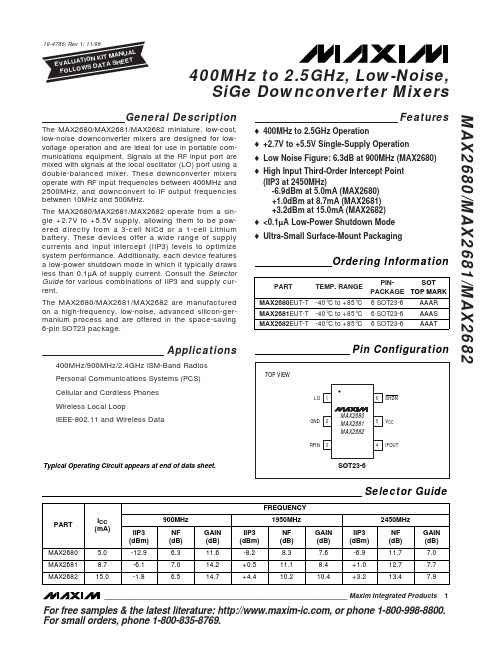
MAX2680-MAX2682中文资料

ICC
ICC VIH VIL ISHDN
MAX2680 MAX2681 MAX2682 SHDN = 0.5V
0 < SHDN < VCC
5.0
7.7
8.7
12.7
mA
15.0 21.8
0.05
5
µA
2.0
V
0.5
V
0.2
µA
AC ELECTRICAL CHARACTERISTICS
(MAX2680/1/2 EV Kit, VCC = SHDN = +3.0V, TA = +25°C, unless otherwise noted. RFIN and IFOUT matched to 50Ω. PLO = -5dBm, PRFIN = -25dBm.)
DC ELECTRICAL CHARACTERISTICS
(VCC = +2.7V to +5.5V, SHDN = +2V, TA = TMIN to TMAX unless otherwise noted. Typical values are at VCC = +3V and TA = +25°C. Minimum and maximum values are guaranteed over temperature by design and characterization.)
10
500 MHz
Conversion Power Gain
fRF = 400MHz, fLO = 445MHz, fIF = 45MHz fRF = 900MHz, fLO = 970MHz, fIF = 70MHz fRF = 1950MHz, fLO = 1880MHz, fIF = 70MHz (Note 1) fRF = 2450MHz, fLO = 2210MHz, fIF = 240MHz
西门子 NXGPro+ 控制系统手册_操作手册说明书

3.4
单元通讯的协议 ............................................................................................................ 36
3.5
NXGpro+ 高级安全 .......................................................................................................37
3.2
功率拓扑 ......................................................................................................................34
3.3
控制系统概述 ...............................................................................................................35
NXGPro+ 控制系统手册
NXGPro+ 控制系统手册
操作手册
AC
A5E50491925J
安全性信息
1
安全注意事项
2
控制系统简介
3
NXGPro+ 控制系统简介
4
硬件用户界面说明
5
参数配置/地址
6
运行控制系统
7
高级的操作功能
8
软件用户界面
9
运行软件
10
故障和报警检修
11
SWDC-Max技术参数手册说明书

塞斯纳 208B
435
63% 85% 92% 96%
国王
500
57% 83% 91% 95%
PC-12
系统参数
体积 ( 长 * 宽 * 高)
SWDC-Max6C:663*560*635mm SWDC-Max6A:490*480*800mm
工作温度
0 ~ 40℃
工作电压
28V
工作电流
15A
最大功率
442W
如何选择快门速度
物方像移量(CM)
快门速度(s)
1/2500 1/2000 1/1600 1/1250 1/1000 1/800
R44
150km/h 2
2
3
3
4
5
贝尔 206
运 -5
小松鼠 B3 180km/h 2
3
3
4
5
6
贝尔 407
PC-6
230km/h 3
3
4
5
6
8
P-750
240km/h 3
SWDC-Max 技术参数手册
SWDC-Max C 型
SWDC-Max A 型
Max7
Max6
Max3
基础参数
镜头数
6个
幅面大小 像元大小 焦距组合
SWDC-Max3:三拼幅面 34000*14000 像元 SWDC-Max6:下视幅面 20000*13000 像元
倾斜幅面 14204*10652 像元
如何选择焦距
GSD(cm) 2 5 10 15
航高(单位:m)
70mm
90mm
372
479
931
1197
6675芯片参数

6675芯片参数
MAX6675是一款常用的接口芯片,广泛应用于温度测量和转换的应用中。
该芯片是将热电偶的温度转换为数字输出的重要工具。
下面是MAX6675的主要参数:
1. 转换精度:MAX6675具有10位转换精度,可将10mV/°C的热电偶温度转换为数字信号,确保了温度测量的精确性。
2. 输出信号类型:MAX6675的输出信号可以是差分或者单端数字信号,用户可根据具体需求进行选择。
3. 温度范围:MAX6675的温度范围为-40℃至+125℃,这意味着它可以测量较宽的温度范围,适应不同的应用场景。
4. 电源电压:MAX6675的工作电压范围为4.75V至
5.25V,它可以接受标准的DC12V直流电源供电。
5. 接口:MAX6675采用了简单易用的接口,只需将电源连接到Vin 和GND,数据引脚连接到数字IO引脚,包括CLK、DO和CS,方便用户进行集成。
6. 封装:MAX6675有多种封装可供选择,包括SOT23-6、TSSOP16和SOIC16等,用户可以根据需求进行选择。
MAX6675芯片的广泛应用和高性能参数,使其成为了温度测量和转换领域的重要工具。
Maxim Integrated产品MAX9638评估板说明说明书

_______________________________________________________________ Maxim Integrated Products 1For pricing, delivery, and ordering information, please contact Maxim Direct at 1-888-629-4642, or visit Maxim’s website at .MAX9638 Evaluation KitEvaluates: MAX9638General DescriptionThe MAX9638 evaluation kit (EV kit) provides a proven design to evaluate the MAX9638 low-power, low-noise, CMOS input op amp, which is suitable for photodiode transimpedance front-ends in portable medical instruments. The EV kit circuit is preconfigured as a noninverting amplifier, but can easily be adapted to other topologies by changing a few components. The EV kit comes with a MAX9638AVB+ installed.FeaturesS Accommodates Noninverting and DifferentialOp-Amp ConfigurationsS Component Pads Allow for Lowpass andHighpass Sallen-Key FilterS Proven PCB LayoutS Fully Assembled and TestedOrdering Information19-5577; Rev 0; 9/10+Denotes lead(Pb)-free and RoHS compliant.Component ListComponent SupplierNote: Indicate that you are using the MAX9638 when contacting this component supplier.PARTTYPEMAX9638EVKIT+EV Kit DESIGNATION QTY DESCRIPTIONR3, R4, R7, R9, R13, R140Not installed, resistors (0603)R5, R10210k I Q 1% resistors (0603)R6, R8, R11, R1240I Q 5% resistors (0603)TP1–TP88Red test pointsU11Dual low-power, rail-to-rail I/O op amp (10 UTQFN)Maxim MAX9638AVB+—4Shunts (JU1–JU4)—1PCB: MAX9638 EVALUATION KIT+SUPPLIERPHONEWEBSITEMurata Electronics North America MAX9638 Evaluation Kit E v a l u a t e s : M A X 96382 ______________________________________________________________________________________Quick StartRequired Equipment• MAX9638 EV kit • 3.3V DC power supply (e.g., Agilent E3620A)• Precision voltage source •Digital multimeter (DMM)ProcedureThe EV kit is fully assembled and tested. Follow the steps below to verify board operation:1) Connect the positive terminal of the power supply tothe VDD pad and the ground terminal to the nearest GND and VSS pads.2) Connect the positive terminal of the precision voltagesource to INAP (TP2). Connect the negative terminal of the precision voltage source to the GND pad.3) Connect the INAM (TP1) to the GND pad.4) Connect the DMM to monitor the voltage on OUTA(TP4). With the 10k I feedback resistor (R5) and 1k I series resistor (R1), the gain is 11 (noninverting con-figuration).5) Turn on the 3.3V power supply.6) Apply 100mV from the precision voltage source.Observe the output at OUTA on the DMM. OUTA should read approximately 1.1V.7) Apply 200mV from the precision voltage source.OUTA should read approximately 2.2V.Detailed Description of HardwareThe MAX9638 EV kit provides a proven design to evaluate the MAX9638 low-power, low-noise, CMOS input op amp, which is suitable for photodiode tran-simpedance front-ends in portable medical instruments. The EV kit circuit is preconfigured as a noninverting amplifier, but can easily be adapted to other topologies by changing a few components.Op-Amp ConfigurationsThe device is a single-supply op amp that is ideal for differential sensing, noninverting amplification, buffering, and filtering. A few common configurations are shown in the next few sections.Noninverting ConfigurationThe EV kit comes preconfigured as a noninverting ampli-fier. The gain is set by the ratio of R5 and R1 for op amp A and R10 and R15 for op amp B. The EV kit comes pre-configured for a gain of 11 on both op amps. The output voltage for the noninverting configuration is given by the equation below:OUTA INAP OS R5V (1)(V V )R1=++andOUTB INBP OS R10V (1)(V V )R15=++Table 1. Jumper Descriptions (JU1–JU4)*Default position.JUMPER SHUNT POSITIONDESCRIPTIONJU11-2*Connects SHDNA of the device to VDD to put U1-A (op amp A) in normal operation. 2-3Connects SHDNA of the device to VSS to put op amp A in shutdown mode.JU21-2*Connects SHDNB of the device to VDD to put U1-B (op amp B) in normal operation. 2-3Connects SHDNB of the device to VSS to put op amp B in shutdown mode.JU31-2*Connects INA+ to INAP (TP2) through R2 and R8.2-3Connects INA+ to GND through R2 and R8.JU41-2*Connects INB+ to INBP (TP6) through R12 and R16.2-3Connects INB+ to GND through R12 and R16.MAX9638 Evaluation KitEvaluates: MAX9638_______________________________________________________________________________________ 3Differential AmplifierTo configure the EV kit as a differential amplifier, replace R1, R2, R3, and R5 with appropriate resistors for op amp A and R9, R10, R15, and R16 for op amp B. When R1 = R2 and R5 = R3, and R10 = R9 and R15 = R16, the CMRR of the differential amplifiers is determined by the matching of the resistor ratios R1/R2 and R3/R5, and R9/R10 and R15/R16:OUTA INAP INAM V GainA (V V )=−where:R5R3GainA R1R2==andOUTB INBP INBM V GainB (V V )=−where:R10R9GainB R15R16==Sallen-Key ConfigurationThe Sallen-Key topology is ideal for filtering sensor signals with a 2nd-order filter and acting as a buffer. Schematic complexity is reduced by combining the filter and buffer operations. The EV kit can be configured in a Sallen-Key topology by replacing and populating a few components. The Sallen-Key topology is typically configured as a unity-gain buffer, which can be done by replacing R1 and R5 with 0I resistors for op amp A. The signal is noninverting and applied to INAP. The filter component pads are R2, R3, R4, and R8, where some have to be populated with resistors and others with capacitors. The same idea applies for op amp B; replace R10 and R15 with 0I resistors and the filter component pads are R9, R12, R14, and R16.Lowpass Sallen-Key FilterTo configure the op amp A Sallen-Key as a lowpass filter, populate the R2 and R8 pads with resistors and populatethe R3 and R4 pads with capacitors.The corner frequency and Q are then given by:C R4R2R8f Q ==The same idea applies for op amp B by replacing R9, R12, R14, and R16 with the appropriate components.Highpass Sallen-Key FilterTo configure the op amp A Sallen-Key as a highpass filter, populate the R3 and R4 pads with resistors and populate theR2 and R8 pads withcapacitors. The corner frequency and Q are then given by:C R3R2R8f Q ==The same idea applies for op amp B by replacing R9, R12, R14, and R16 with the appropriate components.Capacitive LoadsSome applications require driving large capacitive loads. To improve the stability of the amplifiers in such cases, replace R6 and R11 with a suitable resistor value to improve amplifier phase margin.MAX9638 Evaluation Kit E v a l u a t e s : M A X 96384 ______________________________________________________________________________________MAX9638 Evaluation KitEvaluates: MAX9638_______________________________________________________________________________________ 5Component SideMaxim cannot assume responsibility for use of any circuitry other than circuitry entirely embodied in a Maxim product. No circuit patent licenses are implied. Maxim reserves the right to change the circuitry and specifications without notice at any time.6 Maxim Integrated Products, 120 San Gabriel Drive, Sunnyvale, CA 94086 408-737-7600© 2010 Maxim Integrated ProductsMaxim is a registered trademark of Maxim Integrated Products, Inc.MAX9638 Evaluation Kit E v a l u a t e s : M A X 9638Revision HistoryREVISION NUMBERREVISION DATE DESCRIPTIONPAGES CHANGED9/10Initial release—。
MAX在可视倒车雷达中的应用

随着电子技术的飞速发展,汽车倒车辅助系统也发生了巨大的变化。
目前中高档轿车已普遍安装了超声波倒车雷达,帮助司机监控倒车时车尾与车后障碍物的距离,但受限于超声波的传播特性,倒车雷达对车后的细杆状障碍物有漏报现象。
有生产厂家曾尝试将车载视频后视镜与倒车雷达整合,用于观察车后情况和显示倒车雷达测得的数据,以弥补传统倒车雷达性能的不足。
将视频后视镜与倒车雷达整合的核心是视频字符叠加器的设计,由于传统视频字符叠加器结构复杂,在车载环境下可靠性差,造成整合后的可视倒车雷达故障率高,成本高昂,未能在市场上推广。
因此,这里提出一种采用新型视频字符显示芯片MAX7456设计的倒车雷达系统,该系统极大地简化了视频字符叠加器的设计,有效地克服了传统视频字符叠加器的缺点,提高了系统的可靠性,降低了系统成本。
若对该倒车雷达的摄像系统稍加改进,还可扩展出视频变焦、夜视等功能,具有很好的市场前景。
1 MAX7456简介MAX7456是MAXIM公司推出的专用视频字符叠加芯片。
该器件集成了所有用于产生用户定义OSD,并将其插入视频信号中所需的全部功能,即将输入箝位电路、同步分离器、视频时序发生器、OSD插入复用器、EEPROM、显示存储器、OSD发生器、时钟晶体振荡器及SPI通信接口等都集成到了芯片中,用户只需外接一只27 MHz晶振和少量阻容元件,就可构成一个完整的视频字符叠加器。
为方便用户使用,MAX7456内部字符存储器预先装入了256个字符和图形供用户调用。
MAX7456显示字符大小为18x12像素,在屏幕上最多可显示16行x30列=480个字符。
在无视频信号输入时,MAX7456可产生内部视频信号,保证正常的字幕显示。
字符存储器的内容可通过SPI接口进行修改,以满足用户需求。
1.1 端口及功能MAX7456为28引脚封装,其端口功能可划分为视频信号端口、控制信号端口和辅助端口,下面对各端口功能分别加以说明:1)MAX7456的视频信号输入、输出端口为VIN和VOUT。
Autel MaxiScan MS906BT 用户手册说明书

商标深圳市道通科技股份有限公司(以下称”道通公司””)已经在中国及海外若干国家进行了商标注册,Autel® , MaxiSys TM , MaxiDAS® , MaxiScan® ,MaxiTPMS® , MaxiVideo TM ,MaxiRecorder TM,和MaxiCheck TM 均是道通公司的注册商标。
本产品所提及之其它产品及公司名称为其它公司分别所有的商标。
版权信息未征得道通公司的书面同意,任何公司或个人不得以任何形式(电子、机械、影印、录制或其它形式)对本说明书进行复制和备份。
免责声明和责任限制说明书中的所有信息、规格及图示均为出版截止时的最新信息。
道通公司保留对其进行更改而不另行通知的权利。
说明书中的内容已经过认真审核,但不保证其内容(包括但不限于产品规格、功能及图示)的完整性和准确性。
本公司不承担任何直接、间接、特殊、附带的损坏赔偿或任何间接经济损害(包括但不限于利润损失)。
注意:对设备进行操作与维护前,请认真阅读本说明书,尤其是安全注意事项。
服务支持销售服务热线:400-009-3838转1售后服务热线:400-009-3838转2*********************其它国家与地区的用户,请联系当地经销商寻求技术支持。
安全信息为了自身与他人的安全,同时避免对设备及车辆造成损坏,所有操作该设备的人员请务必阅读本手册中所提到的安全注意事项。
由于进行车辆维修时会运用各种程序、工具、部件及技术,同时工作人员的操作方式也各有不同,但因诊断应用程序和该设备所检测产品的种类繁多,本手册无法对每种情况进行预测并提供安全建议。
汽车维修技术人员有责任对所测试的系统进行充分的了解,并合理使用适当的维修方法和测试程序。
进行测试时,必须使用适当的操作方法,以避免对自身和工作区域内其他人员的人身安全造成威胁,同时避免对正在使用的设备或正在测试的车辆造成损坏。
GSK928MA铣床数控系统

GSK928MA 铣床数控系统一性能简介控制轴X Z Y C 四轴 最小指令单位0.01mm 插补方式直线园弧攻丝插补 位置指令范围9999.999mm 最高快速速度16000 mm/min最高进给速度3000mm/min 每转进给无进给倍率0150%实时调节快速倍率手动方式下25%50%75%100%四级加减速方式起始速度,升降速时间参数可调 运动控制功能 电子齿轮比无 电子手轮功能有显示器类型160128点阵式绿底液晶LCD LED 背光显示界面 显示方式可设置为中文或英文菜单 图形显示功能无 功能 共49种G 代码包括22种循环加工指令可进行参数编程可读/写2点用户输入/3点用户输出固定循环功能 共13种指令用一个程序段完成多个程序段指令完成的钻镗攻丝等加工动作使程序得以简化反向间隙补偿X Y Z A 轴自动过象限 补偿 功能 刀具补偿刀具长度补偿与刀具半径补偿 对刀方式定点对刀试切对刀 刀具功能 刀补执行方式自动方式控制方式可设置为4位编码/档位输出0~10V 模拟量输出 档位控制2档主动/被动换档方式 模拟控制 0~10V 输出 主轴功能 恒线速切削功能无辅助功能 主轴正转反转停止冷却启停润滑启停2点用户输入3点用户输出程序容量28KB 100个程序 格式ISO 代码相对/绝对混合编程 程序编辑 子程序可编辑最多3级嵌套通讯 RS232通讯接口为标准配置可选配通讯功能提供通讯软件及通讯电缆与PC 机双向传送程序开关电源GSK PC 配套提供已安装连接适配部件驱动装置DF3三相反应式DY3三相混合式DA98交流伺服标准面板大面板箱式装配形式 一体化配DF3A 或DY3驱动装置下出线一体化后出线二产品型谱1型号意义GSK 928MA装配形式无小面板368298mmL大面板424304mmB箱式装配928MA系列铣床数控系统广州数控产品标志2型谱订货型号说明GSK928MA 368298mm平面操作面板GSK928MA-L 424304mm平面操作面板GSK928MA-B GSK928MA-L箱式装配GSK928MA-DF3A与DF3A一体化装配下出线箱式底孔出线GSK928MA-DF3A-B 与DF3A一体化装配后出线箱背航空插座出线GSK928MA-DY3-B 与DY3一体化装配后出线箱背航空插座出线GSK928MA-DY3与DY3一体化装配下出线箱式底孔出线GSK928MA-DY3A与DY3A一体化装配下出线箱式底孔出线GSK928MA-DY3A-B 与DY3A一体化装配后出线箱背航空插座出线注”为4位阿拉伯数字前2位代表X轴驱动器规格后2位代表Z轴驱动规格00表示该轴驱动器不安装单轴一体化3软件版本版本号说明V2.0 标准软件产品功能见说明书V114 专用软件X Y Z轴脉冲分别114倍频输出V222 专用软件X Y Z轴脉冲全部2倍频输出4标准附件GSK PC开关电源盒已装配插接件产品接口连接用插接件附件电缆成套供货的部件间连接电缆不含交流电源电缆标准长度为3米特殊长度需注明抗干扰组件1N400780.1F/630V 6随机技术文件产品说明书5订货时需注明的项目5.1 选配功能通讯提供通讯软件(3.5寸软盘壹张)5米通讯电缆壹条用于与PC机传送程序DNC提供通讯软件(3.5寸软盘壹张)5米通讯电缆壹条用于与PC机进行DNC通讯也可实现与PC机传送程序5.2 选配选装件电源滤波器FN2060-6-06选配时装配交货电子手轮仅可作为附件交货用户自行安装长春LGF-001-100东信RE45T1SO5B1可选急停按钮LAY3-02ZS/1(箱式一体化装配时为标准安装件用作电源开关)按钮不自锁按钮绿色或红色KH-516-B11自锁式按钮绿色或红色KH-516-B21通常作为附件交货要求安装接线时应说明安装接线要求大面板箱式一体最多可安装16安装孔按钮6只22安装孔按钮1只特殊附件电缆特殊长度要求的附件电缆其它标准附件以外的其它选配件5.3 用户对产品硬件软件配置和装配的特殊要求应特别说明必要时应提供书面技术要求三外观及尺寸安装图1GSK928MA标准面板外形安装尺寸图广州数控设备厂技术部广州数控设备厂 技术部急停用户安装加工图6-16预留孔C N C S e r i e s 928M A广州数控设备厂 技术部急停928M AC N C S e r i e s 预留孔均布广州数控设备厂技术部广州数控设备厂 技术部航空插头最大尺寸X 向电机Z 向电机电源机床控制(6A )保危F U S E刀架接口编码器通讯J 1J 2J 3J 4J 5J 6J 7广州数控设备厂技术部广州数控设备厂 技术部航空插头最大尺寸X 向电机Z 向电机电源F U S E(6A )保险机床控制刀架接口编码器通讯J 1J 2J 3J 4J 5J 6J 7四连接1接口位置图背视广州数控设备厂技术部电话************8199947382088008 传真************23。
光敏传输器PT928-6C技术数据表说明书

Technical Data Sheet1.5mm Side Looking PhototransistorPT928-6CFeatures․Fast response time ․High sensitivity․Small junction capacitance ․Pb free․This product itself will remain within RoHS compliant version.DescriptionsPT928-6C is a phototransistor in miniature package which is molded in a water clear plastic with spherical top view lens. The device is spectrally matched to infrared emitting diode.Applications․Optoelectronic switch ․VCR ,Video Camera ․Floppy disk drive․Infrared applied systemDevice Selection GuideChip LED Part No.MaterialLens ColorPT928-6C Silicon Water ClearPT928-6C Package DimensionsNotes: 1.All dimensions are in millimeters2.Tolerances unless dimensions ±0.25mmPT928-6CAbsolute Maximum Ratings (Ta=25℃)Parameter SymbolRating UnitsCollector-Emitter Voltage V CEO 30 V Emitter-Collector-Voltage V ECO 5 V Collector Current I C 40 mAOperating Temperature Topr-25 ~ +85℃ ℃ Storage Temperature Tstg -40 ~ +85℃ ℃ Lead Soldering TemperatureTsol260℃Power Dissipation at (orbelow) 25℃ Free Air TemperatureP D 75 mW Notes: *1:Soldering time ≦5 seconds.Electro-Optical Characteristics (Ta=25℃)Parameter Symbol Condition Min.Typ.Max. UnitsCollector – EmitterBreakdown Voltage BV CEO I C =100μAEe=0mW/cm 2 30 --- --- V Emitter-Collector Breakdown Voltage BV ECO I E =100μA Ee=0mW/cm 2 5--- --- VCollector-Emitter Saturation Voltage V (CE)(sat) I C =2mA Ee=1mW/cm 2--- --- 0.4VRise Time t r --- 15 ---Fall Timet f V CE =5VI C =1mARL=1000Ω--- 15 --- μS Collector Dark Current I CEO Ee=0mW/cm 2V CE =20V --- --- 100 nAOn State Collector Current I C(on) Ee=0.555mW/cm 2V CE =5V0.53 3.41 mAWavelength of Peak Sensitivityλp ------ 940 --- nmRang of Spectral Bandwidth λ0.5--- 400 --- 1200 nmPT928-6CParameter SymbolMinMaxUnit Test condition7-3 0.53 1.197-2 0.88 1.707-1 1.24 2.216-2 1.59 2.98 6-1I C(ON) 1.77 3.41mA V CE =5VEe=0.555mW/cm 2Reliability Test Item And ConditionThe reliability of products shall be satisfied with items listed below. Confidence level:90%consent.。
AVX 产品说明书:9286系列电线-到-电线连接器

Wire-to-Wire connectors have been used in the industrial market for years with traditional 2-Piece (plug and socket) connector systems which require crimp and poke wire terminations to connect electrical or electronic components. In the general wiring market (2-3 wires) there are a number of connector styles available, however, they are limited in sizes, expanded wire gauges and the ability to reuse them when repair or replacement is needed. Based on the existing success of “Poke Home” wire-to-board connectors,AVX has developed a new family of wire-to-wire connectors to meet the cost, flexibility and ease-of-use targets in industrial wiring applications.The 9286 series of Thru-Wire connectors provides a high spring force Beryllium Copper contact system that uses simple push button activation to insert and remove individual stripped wires in the connection process. There is a forward and aft shrouded (to prevent accidental activation) push button for each wire connection that can be operated individually or simultaneously with a simple plastic tool or ball point pen tip. Up to eight wires can be electrically connected in a single connector body which will support any combination of wire gauges from 18AWG up to 26 AWG. Wires can be removed orreplaced up to 5 times so there is no need to replace the connector in a new installation.ELECTRICAL• Current Rating: 8 Amps / Contact • Voltage Rating: 250v AC9286Series00Prefix00XNumber of Ways06Plating Option 06 = Pure Tinall overHOW TO ORDERXInsulator Color021Wire SizeCode Color Application1WhiteStandardENVIRONMENTAL• Operating Temperature: -40ºC to +125ºCMECHANICAL• Insulator Material: Glass-Filled Nylon 46; UL94V0• Contact Material: Beryllium Copper /Phosphor Bronze• Plating: Tin over Nickel • Replacibility: 5 CyclesCode No of Details Ways 0011Page 30022Page 40033Page 50044Page 60066Page 70088Page 8Code Wire MaxMaxGauge ConductorInsulation 02118 to 26 1.05mm2.10mm AWG DiameterDiameter18-26 AWG 1 WAY POKE HOME –THRU WIRENOTES:1. 1 WAY WIRE TO WIRE “POKE HOME” CONNECTOR, BUTTON OPERATED.2. WIRE SIZES 18-26 AWG, MAXIMUM INSULATION DIAMETER 2.10MM.3. SPLIT BUTTON ALLOWS THE WIRES TO BE INSERTED/WITHDRAWN INDEPENDENTLY.4. INSULATION MATERIAL: NYLON 46, GLASS FILLED, UL94 V-0. COLOR SEE PAGE 2.5. CONTACT MATERIAL: TIN PLATED COPPER ALLOY.6. FOR FULL SPECIFICATION REFER TO ELCO SPECIFICATION 201-01-132.FOR APPLICATION NOTES REFER TO ELCO SPECIFICATION 201-01-135.7. GENERAL TOLERANCE ±0.20MM.18-26 AWG 2 WAY POKE HOME –THRU WIRENOTES:1. 2 WAY WIRE TO WIRE “POKE HOME” CONNECTOR, BUTTON OPERATED.2. WIRE SIZES 18-26 AWG, MAXIMUM INSULATION DIAMETER 2.10MM.3. SPLIT BUTTON ALLOWS THE WIRES TO BE INSERTED/WITHDRAWN INDEPENDENTLY.4. INSULATION MATERIAL: NYLON 46, GLASS FILLED, UL94 V-0. COLOR SEE PAGE 2.5. CONTACT MATERIAL: TIN PLATED COPPER ALLOY.6. FOR FULL SPECIFICATION REFER TO ELCO SPECIFICATION 201-01-132.FOR APPLICATION NOTES REFER TO ELCO SPECIFICATION 201-01-135.7. GENERAL TOLERANCE ±0.20MM.18-26 AWG 3 WAY POKE HOME –THRU WIRENOTES:1. 3 WAY WIRE TO WIRE “POKE HOME” CONNECTOR, BUTTON OPERATED.2. WIRE SIZES 18-26 AWG, MAXIMUM INSULATION DIAMETER 2.10MM.3. SPLIT BUTTON ALLOWS THE WIRES TO BE INSERTED/WITHDRAWN INDEPENDENTLY.4. INSULATION MATERIAL: NYLON 46, GLASS FILLED, UL94 V-0. COLOR SEE PAGE 2.5. CONTACT MATERIAL: TIN PLATED COPPER ALLOY.6. FOR FULL SPECIFICATION REFER TO ELCO SPECIFICATION 201-01-132.FOR APPLICATION NOTES REFER TO ELCO SPECIFICATION 201-01-135.7. GENERAL TOLERANCE ±0.20MM.18-26 AWG 4 WAY POKE HOME –THRU WIRENOTES:1. 4 WAY WIRE TO WIRE “POKE HOME” CONNECTOR, BUTTON OPERATED.2. WIRE SIZES 18-26 AWG, MAXIMUM INSULATION DIAMETER 2.10MM.3. SPLIT BUTTON ALLOWS THE WIRES TO BE INSERTED/WITHDRAWN INDEPENDENTLY.4. INSULATION MATERIAL: NYLON 46, GLASS FILLED, UL94 V-0. COLOR SEE PAGE 2.5. CONTACT MATERIAL: TIN PLATED COPPER ALLOY.6. FOR FULL SPECIFICATION REFER TO ELCO SPECIFICATION 201-01-132.FOR APPLICATION NOTES REFER TO ELCO SPECIFICATION 201-01-135.7. GENERAL TOLERANCE ±0.20MM.8. WIRE STRIP LENGTH GUIDE, SEE PAGE 1318-26 AWG 6 WAY POKE HOME –THRU WIRENOTES:1. 6 WAY WIRE TO WIRE “POKE HOME” CONNECTOR, BUTTON OPERATED.2. WIRE SIZES 18-26 AWG, MAXIMUM INSULATION DIAMETER 2.10MM.3. SPLIT BUTTON ALLOWS THE WIRES TO BE INSERTED/WITHDRAWN INDEPENDENTLY.4. INSULATION MATERIAL: NYLON 46, GLASS FILLED, UL94 V-0. COLOR SEE PAGE 2.5. CONTACT MATERIAL: TIN PLATED COPPER ALLOY.6. FOR FULL SPECIFICATION REFER TO ELCO SPECIFICATION 201-01-132.FOR APPLICATION NOTES REFER TO ELCO SPECIFICATION 201-01-135.7. GENERAL TOLERANCE ±0.20MM.18-26 AWG 8 WAY POKE HOME –THRU WIRENOTES:1. 8 WAY WIRE TO WIRE “POKE HOME” CONNECTOR, BUTTON OPERATED.2. WIRE SIZES 18-26 AWG, MAXIMUM INSULATION DIAMETER 2.10MM.3. SPLIT BUTTON ALLOWS THE WIRES TO BE INSERTED/WITHDRAWN INDEPENDENTLY.4. INSULATION MATERIAL: NYLON 46, GLASS FILLED, UL94 V-0. COLOR SEE PAGE 2.5. CONTACT MATERIAL: TIN PLATED COPPER ALLOY.6. FOR FULL SPECIFICATION REFER TO ELCO SPECIFICATION 201-01-132.FOR APPLICATION NOTES REFER TO ELCO SPECIFICATION 201-01-135.。
MAX9867 超低功耗立体声音频编解码器

MAX9867 超低功耗立体声音频编解码器MAX9867 是一款超低功耗立体声音频编解码器,设计用于手机和便携式游戏机等便携式消费类电子产品。
该器件具有立体声差分麦克风输入,可连接至模拟或数字麦克风。
单端线入信号经过可配置前置放大器,能够输入到ADC 用于录音或直接切换到耳机放大器用于回放。
辅助ADC 通道可用于跟踪任何直流电压。
立体声耳机放大器支持差分、单端以及无滤波电容的输出配置。
采用无滤波电容输出配置时,器件可为32Ω负载提供10mW 输出功率。
完备的咔嗒/噼噗声抑制电路能够在音量变化、启动或关断过程中消除可闻噪声。
采用Maxim 专有的数字电路,器件可接受任何10MHz 至60MHz 范围的系统时钟。
该架构省去了外部PLL 和多个晶体振荡器。
立体声ADC 和DAC通道提供用户可配置的语音频段或音频频段的数字滤波器。
语音频段滤波器在GSM 分组频段提供额外的衰减,在fS/2 频点具有大于70dB 的阻带衰减。
MAX9867 采用1.8V 单电源供电,支持1.65V 至3.6V 逻辑电平。
可通过2 线、I²C串行接口控制音量、信号混音以及常规工作模式。
MAX9867 采用小尺寸、2.2mm x 2.7mm、0.4mm 焊球间距的WLP 封装。
另外还可提供32 引脚、5mm x 5mm TQFN 封装。
关键特性1.8V 单电源供电6.7mW 回放功耗90dB 立体声DAC,8kHz ≤fS ≤48kHz85dB 立体声ADC,8kHz ≤fS ≤48kHz辅助ADC,用于电池测量支持10MHz 至60MHz 任意主时钟频率支持立体声数字麦克风输入立体声模拟差分麦克风输入立体声耳机放大器:差分、单端或无滤波电容三种配置立体声线入语音频段滤波器,阻带衰减大于70dB1.65V 至3.6V 数字接口供电电源I²S/TDM兼容的数字音频总线30 焊球、2.2mm x 2.7mm、0.4mm 间距的WLP 封装tips:感谢大家的阅读,本文由我司收集整编。
光速928 tea说明书

光速928 tea说明书安全警告操作不当可能引起意外事故。
在使用本系统以前,请务必仔细阅读本册!在系统开始使用之前,请注意以下事项:连接好系统的急停按钮。
由于本系统的急停输入采用常闭触点,如不接好急停按钮或错接为常开触点,系统通电后会产生急停报警而不能正常工作(这不属于系统故障)。
根据刀具的实际安装位置设置好程序参考点,如不设置好参考点就使用回程序参考点功能,将可能发生意外!特别提示:安装在机箱上(内)的系统电源,是仅为本公司制造的数控。
系统提供的专用电源。
禁止用户将这个电源作其他用途使用。
否则,将产生极大的危险!安全注意事项在本系统连接、使用之前,请务必仔细阅读安全注意事项。
用户必须遵守安全操作规程,以确保人身及设备安全。
用户操作时还必须遵守由本公司提供的使用手册中指明的相关安全规程,在完全熟悉本使用手册内容后,方可操作本系统。
用户还必须遵守由机床厂商随行提供的机床使用说明书中指明的与机床有关的安全操作规程。
用户必须在完全熟悉本使用手册以及由制造厂商随行提供的机床使用说明书的内容后,才能操作机床或编制程序来控制机床。
1、图形符号定义!警告表示如果不按指定方法或步骤操作,可能造成人员伤亡。
!报警表示错误的操作,可能造成人员伤害及设备损坏。
!注意表示使用不当,可能造成设备及产品损坏。
!表示特别重要内容。
2、注意事项(1)验收小心损坏或有故障的产品不允许投入使用。
(2)运输与储存注意运输与储存中应注意防潮,不可在产品包装箱上攀爬或站立,也不可在上面放置重物;产品包装箱的堆放数量有限,不可过多地堆叠在一起,一般的堆放数量为5箱。
前面板和显示屏应特别注意防止碰撞与划伤。
(3)安装小心数控系统的外壳非防水设计,安装时应防止日晒及雨淋。
注意数控系统安装应防止尘埃、腐蚀性气体、导电物体、液体及易燃物侵入。
数控系统应安装在远离易燃、易爆物品、及强电磁干扰的场所。
数控系统安装必须牢固,避免振动。
(4)接线警告!参与接线或检查的人员都必须具有做此项工作的充分能力;连接电线不可有破损,不可受挤压不可带电打开数控系统机箱。
JBL VRX928LA 8英寸两路线阵扬声器系统说明书

᭤VRX928LA 8" Two-Way Line Array Loudspeaker System SHORT THROWMID THROWLONG THROW1+1-2-2+1+1-2-2+1+1-2-2+1+1-2-2+NL4INPUTNL4INPUTLPFPASSIVE MODEBI-AMP MODE-3 dB0 dB+3 dB NL4INPUT NL4INPUT HPFBlock DiagramArray Configuration Selector (ACS)Amplitude shading is a technique that allows the coverage pattern of a loudspeaker array to be shaped by adjusting the relative acoustic output of some of the devices in the array. Most often, array shading involves only the mid and high-frequency sections of the array. In a simple system consisting of three VRX928LAs, the lower speaker (which covers the nearest listeners) may have its high-frequency output reduced. At thesame time, the upper speaker may have its high frequency output increased. The overall sound-power in the room is unchanged but the distribution of acoustic energy to the audience is far more uniform.Amplitude shading of a VRX928LA array may be accomplished in passive or bi-amplified systems.In passive mode, the Array Configuration Selector may be used. The -3 dB position will typically be used for the speaker(s) in an array that are covering the nearest listening area. The +3 dB position will be used for the speaker(s) covering the more distant areas, or to compensate for the low-frequency build-up resulting from mutual coupling of multiple woofers in an array. In bi-amp mode the amplifier output needs to be adjusted accordingly.Serial No.VRX928LABI-AMPBI-AMP ±1 LF: 8±2 HF: 16⍀⍀PASSIVEPASSIVE ±1 IN: 8±2 N/C⑁Array Configuration Selector HF Output LevelVRX928LA-SMAF Array Frame AccessoryThe VRX928LA-SMAF is an array frame kit designed to be used for suspension of the VRX928LA line array loudspeaker. The optional array frame kit includes an array frame, two quick release pins, a pair of forged 3/8"shackles, and a pair of drop levers.The following table defines the maximum number of speakers that may be suspended using the VRX-SMAF frame. A minimum design factor of 7:1 is maintained for all speaker configurations at or below those indicated in the table.Maximum number of VRX928LA in array 654320Maximum number of VRX915S in array22234For some applications, it may be necessary to pull back the array from the bottom in order to achieve the desired coverage. Every VRX-SMAF is supplied with a spare set of quick release pins and a pair of spare droplevers that are used to adapt a second array frame to the bottom of a VRX928LA array. Once these are installed on the bottom enclosure, the array frame may be attached as previously described.Ground-Stacked, Upward Firing Arrays: Applications may be addressed by installing the VRX-SMAF array frame to the bottom of the array as described above. Up to four VRX928LA loudspeakers may be locked together and ground stacked using the VRX-SMAF array frame kit.Northridge, California 91329 U.S.A.A©。
Maxim Integrated推出支持4路全景视频信号流的解串器,理想用于汽车产品

Maxim Integrated推出支持4路全景视频信号流的解串器,
理想用于汽车产品
佚名
【期刊名称】《电源技术应用》
【年(卷),期】2015(0)7
【摘要】中国,北京,2015年7月28日。
Maxim Integrated ProdUCtS.InC.(NASDAQ:MXIM)推出GMSL四通道解串器MAX9286,
以更少元件、更短时间实现ADAS(高级驾驶辅助系统)的环视系统设计。
仅需一片MAX9286吉比特多媒体串行链路(GMSL)解串器,即可接收并自动同步来自
4个摄像头的视频信号。
【总页数】1页(PI0003-I0003)
【关键词】Integrated;Maxim;解串器;全景视频;汽车产品;信号流;驾驶辅助系统;理想
【正文语种】中文
【中图分类】TP332
【相关文献】
1.Maxim公司推出支持4路全景视频信号流的解串器 [J],
2.Maxim推出高速LVDS串行器解串器(SerDes)新产品 [J],
3.支持4路全景视频信号流的解串器 [J],
4.Maxim Integrated推出串行器/解串器(SerDes)芯片组 [J],
5.Maxim针对汽车市场推出支持4路全景视频信号流的解串器 [J],
因版权原因,仅展示原文概要,查看原文内容请购买。
- 1、下载文档前请自行甄别文档内容的完整性,平台不提供额外的编辑、内容补充、找答案等附加服务。
- 2、"仅部分预览"的文档,不可在线预览部分如存在完整性等问题,可反馈申请退款(可完整预览的文档不适用该条件!)。
- 3、如文档侵犯您的权益,请联系客服反馈,我们会尽快为您处理(人工客服工作时间:9:00-18:30)。
Course Introduction and Overview
• Application: In surround-view camera applications, video data from multiple cameras need to be synchronized for processing by a downstream SoC • Limitation of Current Solution: Using single-channel deserializers available today, the video streams need to be synchronized using an FPGA and related software • Implication: Synchronizing multiple video streams using today’s technology requires additional hardware and software • Advantage of Maxim Solution: The MAX9286 allows automatic camera synchronization with no additional hardware or software, thereby lowering design time and cost. The MAX9286 also has link diagnostic features to determine the health of each camera link.
End Applications
Surround-view camera systems Machine vision systems
1.5Gbps STP or coax Cable ≤15M
ECU 9286 Quad Des (1.5Gbps/ch) SoC Processor
CSI Memory uC 4-lane CSI-2 Out 4-lane CSI-2 In ISP
ABCs of MAX9286 Product Training
MAX9286: Quad 1.5Gbps GMSL Deserializer with Coax/STP Input and CSI-2 Output
Objectives
By the end of this course, you should be able to: • Identify the customer challenges and problems addressed by the MAX9286 • Explain what we do to help resolve those challenges • Describe the system block diagram • Articulate the product’s value proposition, features, benefits and competitors • Overcome common competitor objections • Navigate through Maxim’s resources to help close the deal • Provide the vision for the next generation product update • Leverage additional resources to help sell and position this product
1M Price Availability EvKit
Competition
Sensor
I2C
9271
I2C
Des
I2C
$6.10 Stock MAX9286C OAXEVKIT#
DS90UB914
Sensor
I2C
9271
I2C
Des
I2C
Sensor
I2C
9271
I2C
Des
I2C
Sensor
I2C
I2C
4-lane CSI-2 Input
ISP
Overview
• MAX9286
Benefits
Lowers system design time Lowers system cost Simplifies system troubleshooting
Features
Automatic camera sync One CSI-2 output for up to 4 cameras Line fault detect
Deserializer MAX9240
I2C
Sensor
I2C
9271
I2C
Deserializer MAX9240
I2C
Memory ISP I2C
oLDI
Serializer
3Gbps STP or coax Cable ≤15M
Deserializer
SoC Processor
4-lane CSI-2 Input ISP
Response
• Camera resolutions are increasing from 1MPixel to 2+Mpixel • MAX9286 allows quicker system design due to its “ease- of use” features
> > > With parallel interfaces this means a large number of pins, which is impractical CSI-2 ports provide an easy path to upgrade to higher resolution cameras MAX9286 has a CSI-2 output, which will be maintained in the next generation of the device
Current Implementation of Surround View Systems
DRAM
1.5Gbps STP or coax Cable ≤15M
Frame Buffer
12-bit Parallel
FPGA
DRAM
Memory Frame Buffer
Sensor
I2C
9271
I2C
MAX9277I2C
MAX9288 I2C
Sensor
I2C
9271
I2C
Deserializer MAX9240
I2C
Memory
I2C
Sensor
I2C
9271
I2C
Deserializer MAX9240
I2C
Memory
(Example sensor resolution and data format: 1280x1080p, 30Hz, 2x11-bit)
| Maxim Integrated | Company Confidential
Summary
Now that you have completed this course, you should be able to: • Identify the customer challenges and problems addressed by the MAX9286 • Explain what we do to help resolve those challenges • Describe the system block diagram • Articulate the product’s value proposition, features, benefits and competitors • Overcome common competitor objections • Navigate through Maxim’s resources to help close the deal • Provide the vision for the next generation product update • Leverage additional resources to help sell and position this product
9271
I2C
Des
I2C
(Example sensor resolution and data format: 1280x1080p, 30Hz, 2x11-bit)
Surround View
I2C
I2C
Overcoming Common Objections
Objection
Our current solution works with 4 discrete parallel deserializers
