STM32F101xx和STM32F103xx闪存加载演示程序
Flash做为存储器存储数据

STM32学习笔记-Flash做为存储器储存数据说到STM32的FLSAH,我们的第一反应是用来装程序的,实际上,STM32的片内FLASH不仅用来装程序,还用来装芯片配置、芯片ID、自举程序等等。
当然, FLASH 还可以用来装数据。
自己收集了一些资料,现将这些资料总结了一下,不想看的可以直接调到后面看怎么操作就可以了。
FLASH分类根据用途,STM32片内的FLASH分成两部分:主存储块、信息块。
主存储块用于存储程序,我们写的程序一般存储在这里。
信息块又分成两部分:系统存储器、选项字节。
系统存储器存储用于存放在系统存储器自举模式下的启动程序(BootLoader),当使用ISP方式加载程序时,就是由这个程序执行。
这个区域由芯片厂写入BootLoader,然后锁死,用户是无法改变这个区域的。
选项字节存储芯片的配置信息及对主存储块的保护信息。
FLASH的页面STM32的FLASH主存储块按页组织,有的产品每页1KB,有的产品每页2KB。
页面典型的用途就是用于按页擦除FLASH。
从这点来看,页面有点像通用FLASH 的扇区。
STM32产品的分类STM32根据FLASH主存储块容量、页面的不同,系统存储器的不同,分为小容量、中容量、大容量、互联型,共四类产品。
小容量产品主存储块1-32KB,每页1KB。
系统存储器2KB。
中容量产品主存储块64-128KB,每页1KB。
系统存储器2KB。
大容量产品主存储块256KB以上,每页2KB。
系统存储器2KB。
互联型产品主存储块256KB以上,每页2KB。
系统存储器18KB。
对于具体一个产品属于哪类,可以查数据手册,或根据以下简单的规则进行区分:STM32F101xx、STM32F102xx 、STM32F103xx产品,根据其主存储块容量,一定是小容量、中容量、大容量产品中的一种,STM32F105xx、STM32F107xx是互联型产品。
互联型产品与其它三类的不同之处就是BootLoader的不同,小中大容量产品的BootLoader只有2KB,只能通过USART1进行ISP,而互联型产品的BootLoader有18KB,能通过USAT1、4、CAN等多种方式进行ISP。
RTC校准
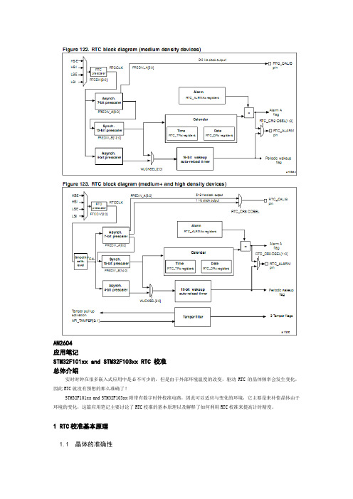
AN2604应用笔记STM32F101xx and STM32F103xx RTC 校准总体介绍实时时钟在很多嵌入式应用中是必不可少的,但是由于外部环境温度的改变,驱动RTC的晶体频率会发生变化,因此RTC就没有预想的那么准确了!STM32F101xx and STM32F103xx附带有数字时钟校准电路,因此可以适应与变化的环境,它主要是来补偿晶体由于环境的变化,这篇应用笔记主要讨论了RTC校准的基本原理以及解释了如何利用RTC校准来提高计时精度。
1 RTC校准基本原理1.1 晶体的准确性在很多计时领域,通常都是用“石英精确度”这么一个术语来描述的,石英晶体振荡器提供了一个远远优于其他类型振荡器的精确度,但是它并不是完美的,石英晶体振荡器对温度十分敏感, Figure 1 展示了一个32.768HZ晶体的频率精确度(acc)和温度(T)以及曲率(K)的关系,这个曲线可以用下面的公式给出:注:曲率K由于不同的晶体而不同,这里是针对STM3210B-EVAL开发板来说的,关于这部分可以参考相关晶体制造商提供的详细信息。
在很多应用领域需要一个高准确度的时钟,但是在实际中有好多综合因素限制着精度的提高,通常,典型的方法是通过调节晶体的负载电容来调节精度,这一方法,虽然十分有效,但是也存在这一些缺点:1 它需要多加一个外部器件(可调电容)。
2 其增大了电流消耗(这在电池供电的场合尤为突出)。
取代这种传统的模拟的方法,STM32F10xxx系列提供了一个数字校准器,允许用户用软件控制的方法进行校准,非常的好用!1.2 具体方法STM32F10xxx 的RTC模块是用一个32768HZ的通常石英晶体驱动的,其实石英晶体是一种能够提供非常固定频率的,但是有以下两种情况导致了其频率的不稳定:1 温度变化;2 晶体本身的变化。
前面讲述了一般通常的方法都是用一个麻烦的可调电容来补偿误差,这里STM32F10xxx 使用的是一个周期计数器来进行校正,这个数字校正器通过从220个时钟周期中减去0到127个周期的方法来校正的,如图所示:究竟有多少个时钟节拍是空白的取决于最近一次向备份寄存区域RTC校准寄存器最后七位加载的值,之所以这个校准寄存器放在备份区域是因为这个寄存器即使在系统掉电情况下仍然可以通过后备电池进行供电(译者注:如果后背电池也掉电,当然这个寄存器的值也会丢失的),注意:从上图中可以看出时钟输出引脚是在校准之前的频率,所以这个值是不会被校准所改变的,尽管已经进行了校准,但是这个输出是在校准之前的频率。
STM32的FLASH操作

关于STM32的FLASH操作说到STM32的FLSAH,我们的第一反应是用来装程序的,实际上,STM32的片内FLASH不仅用来装程序,还用来装芯片配置、芯片ID、自举程序等等。
当然,FLASH还可以用来装数据。
FLASH分类根据用途,STM32片内的FLASH分成两部分:主存储块、信息块。
主存储块用于存储程序,我们写的程序一般存储在这里。
信息块又分成两部分:系统存储器、选项字节。
系统存储器存储用于存放在系统存储器自举模式下的启动程序(BootLoader),当使用ISP方式加载程序时,就是由这个程序执行。
这个区域由芯片厂写入BootLoader,然后锁死,用户是无法改变这个区域的。
选项字节存储芯片的配置信息及对主存储块的保护信息。
FLASH的页面STM32的FLASH主存储块按页组织,有的产品每页1KB,有的产品每页2KB。
页面典型的用途就是用于按页擦除FLASH。
从这点来看,页面有点像通用FLASH的扇区。
STM32产品的分类STM32根据FLASH主存储块容量、页面的不同,系统存储器的不同,分为小容量、中容量、大容量、互联型,共四类产品。
小容量产品主存储块1-32KB,每页1KB。
系统存储器2KB。
中容量产品主存储块64-128KB,每页1KB。
系统存储器2KB。
大容量产品主存储块256KB以上,每页2KB。
系统存储器2KB。
互联型产品主存储块256KB以上,每页2KB。
系统存储器18KB。
对于具体一个产品属于哪类,可以查数据手册,或根据以下简单的规则进行区分:STM32F101xx、STM32F102xx 、STM32F103xx产品,根据其主存储块容量,一定是小容量、中容量、大容量产品中的一种,STM32F105xx、STM32F107xx 是互联型产品。
互联型产品与其它三类的不同之处就是BootLoader的不同,小中大容量产品的BootLoader只有2KB,只能通过USART1进行ISP,而互联型产品的BootLoader 有18KB,能通过USAT1、4、CAN等多种方式进行ISP。
STM32中文参考手册-stm32f103中文参考手册

STM32F10xxx参考手册参考手册小,中和大容量的STM32F101xx, STM32F102xx和STM32F103xxARM内核32位高性能微控制器导言本参考手册针对应用开发,提供关于如何使用小容量、中容量和大容量的STM32F101xx、STM32F102xx或者STM32F103xx微控制器的存储器和外设的详细信息。
在本参考手册中STM32F101xx、STM32F102xx和STM32F103xx被统称为STM32F10xxx。
STM32F10xxx系列拥有不同的存储器容量,封装和外设配置。
关于订货编号、电气和物理性能参数,请参考STM32F101xx、STM32F102xx和STM32F103xx 的数据手册。
关于芯片内部闪存的编程,擦除和保护操作,请参考STM32F10xxx闪存编程手册。
关于ARM Cortex™-M3内核的具体信息,请参考Cortex™-M3技术参考手册。
相关文档● Cortex™-M3技术参考手册,可按下述链接下载:/help/topic/com.arm.doc.ddi0337e/DDI0337E_cortex_m3_r1p1_trm.pdf下述文档可在ST网站下载(/mcu/):● STM32F101xx、STM32F102xx和STM32F103xx的数据手册。
● STM32F10xxx闪存编程手册。
* 感谢南京万利提供原始翻译文档目录1文中的缩写 161.1寄存器描述表中使用的缩写列表 161.2术语表161.3可用的外设16 2存储器和总线构架 172.1系统构架172.2存储器组织182.3存储器映像192.3.1嵌入式SRAM 202.3.2位段202.3.3嵌入式闪存 212.4启动配置23 3CRC计算单元(CRC) 253.1CRC简介253.2CRC主要特性253.3CRC功能描述253.4CRC寄存器263.4.1数据寄存器(CRC_DR) 263.4.2独立数据寄存器(CRC_IDR) 263.4.3控制寄存器(CRC_CR) 273.4.4CRC寄存器映像 27 4电源控制(PWR) 284.1电源284.1.1独立的A/D转换器供电和参考电压 284.1.2电池备份区域 294.1.3电压调节器 294.2电源管理器294.2.1上电复位(POR)和掉电复位(PDR) 294.2.2可编程电压监测器(PVD) 304.3低功耗模式304.3.1降低系统时钟 314.3.2外部时钟的控制 314.3.3睡眠模式 314.3.4停止模式 324.3.5待机模式 334.3.6低功耗模式下的自动唤醒(AWU) 344.4电源控制寄存器 354.4.1电源控制寄存器(PWR_CR) 354.4.2电源控制/状态寄存器 364.4.3PWR寄存器地址映像 37 5备份寄存器(BKP) 385.1BKP简介385.2BKP特性385.3BKP功能描述385.3.1侵入检测 385.3.2RTC校准 395.4BKP寄存器描述 395.4.1备份数据寄存器x(BKP_DRx) (x = 1 … 10) 395.4.2RTC时钟校准寄存器(BKP_RTCCR) 395.4.3备份控制寄存器(BKP_CR) 405.4.4备份控制/状态寄存器(BKP_CSR) 405.4.5BKP寄存器映像 42 6复位和时钟控制(RCC) 456.1复位456.1.1系统复位 456.1.2电源复位 456.1.3备份域复位 466.2时钟466.2.1HSE时钟 486.2.2HSI时钟 486.2.3PLL 496.2.4LSE时钟 496.2.5LSI时钟496.2.6系统时钟(SYSCLK)选择 506.2.7时钟安全系统(CSS) 506.2.8RTC时钟 506.2.9看门狗时钟 506.2.10时钟输出 506.3RCC寄存器描述 516.3.1时钟控制寄存器(RCC_CR) 516.3.2时钟配置寄存器(RCC_CFGR) 526.3.3时钟中断寄存器 (RCC_CIR) 546.3.4APB2外设复位寄存器 (RCC_APB2RSTR) 566.3.5APB1外设复位寄存器 (RCC_APB1RSTR) 586.3.6AHB外设时钟使能寄存器 (RCC_AHBENR) 606.3.7APB2外设时钟使能寄存器(RCC_APB2ENR) 616.3.8APB1外设时钟使能寄存器(RCC_APB1ENR) 626.3.9备份域控制寄存器 (RCC_BDCR) 656.3.10控制/状态寄存器 (RCC_CSR) 666.3.11RCC寄存器地址映像 68 7通用和复用功能I/O(GPIO和AFIO) 697.1GPIO功能描述697.1.1通用I/O(GPIO) 707.1.2单独的位设置或位清除 717.1.3外部中断/唤醒线 717.1.4复用功能(AF) 717.1.5软件重新映射I/O复用功能 717.1.6GPIO锁定机制 717.1.7输入配置 717.1.8输出配置 727.1.9复用功能配置 737.1.10模拟输入配置 737.2GPIO寄存器描述 757.2.1端口配置低寄存器(GPIOx_CRL) (x=A..E) 757.2.2端口配置高寄存器(GPIOx_CRH) (x=A..E) 757.2.3端口输入数据寄存器(GPIOx_IDR) (x=A..E) 767.2.4端口输出数据寄存器(GPIOx_ODR) (x=A..E) 767.2.5端口位设置/清除寄存器(GPIOx_BSRR) (x=A..E) 777.2.6端口位清除寄存器(GPIOx_BRR) (x=A..E) 777.2.7端口配置锁定寄存器(GPIOx_LCKR) (x=A..E) 777.3复用功能I/O和调试配置(AFIO) 787.3.1把OSC32_IN/OSC32_OUT作为GPIO 端口PC14/PC15 787.3.2把OSC_IN/OSC_OUT引脚作为GPIO端口PD0/PD1 787.3.3CAN复用功能重映射 797.3.4JTAG/SWD复用功能重映射 797.3.5ADC复用功能重映射 807.3.6定时器复用功能重映射 807.3.7USART复用功能重映射 817.3.8I2C 1 复用功能重映射 827.3.9SPI 1复用功能重映射 827.4AFIO寄存器描述 837.4.1事件控制寄存器(AFIO_EVCR) 837.4.2复用重映射和调试I/O配置寄存器(AFIO_MAPR) 837.4.3外部中断配置寄存器1(AFIO_EXTICR1) 867.4.4外部中断配置寄存器2(AFIO_EXTICR2) 867.4.5外部中断配置寄存器3(AFIO_EXTICR3) 877.4.6外部中断配置寄存器4(AFIO_EXTICR4) 877.5GPIO 和AFIO寄存器地址映象 88 8中断和事件 898.1嵌套向量中断控制器 898.1.1系统嘀嗒(SysTick)校准值寄存器 898.1.2中断和异常向量 898.2外部中断/事件控制器(EXTI) 918.2.1主要特性 918.2.2框图928.2.3唤醒事件管理 928.2.4功能说明 928.2.5外部中断/事件线路映像 948.3EXTI 寄存器描述 958.3.1中断屏蔽寄存器(EXTI_IMR) 958.3.2事件屏蔽寄存器(EXTI_EMR) 958.3.3上升沿触发选择寄存器(EXTI_RTSR) 968.3.4下降沿触发选择寄存器(EXTI_FTSR) 968.3.5软件中断事件寄存器(EXTI_SWIER) 978.3.6挂起寄存器(EXTI_PR) 978.3.7外部中断/事件寄存器映像 98 9DMA 控制器(DMA) 999.1DMA简介999.2DMA主要特性999.3功能描述1009.3.1DMA处理 1009.3.2仲裁器1009.3.3DMA 通道 1019.3.4可编程的数据传输宽度,对齐方式和数据大小端 1029.3.5错误管理 1039.3.6中断1039.3.7DMA请求映像 1049.4DMA寄存器1079.4.1DMA中断状态寄存器(DMA_ISR) 1079.4.2DMA中断标志清除寄存器(DMA_IFCR) 1089.4.3DMA通道x配置寄存器(DMA_CCRx)(x = 1…7) 1089.4.4DMA通道x传输数量寄存器(DMA_CNDTRx)(x = 1…7) 1109.4.5DMA通道x外设地址寄存器(DMA_CPARx)(x = 1…7) 1109.4.6DMA通道x存储器地址寄存器(DMA_CPARx)(x = 1…7) 1109.4.7DMA寄存器映像 111 10模拟/数字转换(ADC) 11310.1ADC介绍11310.2ADC主要特征11310.3ADC功能描述11410.3.1ADC开关控制 11510.3.2ADC时钟 11510.3.3通道选择 11510.3.4单次转换模式 11510.3.5连续转换模式 11610.3.6时序图11610.3.7模拟看门狗 11610.3.8扫描模式 11710.3.9注入通道管理 11710.3.10间断模式 11810.4校准11910.5数据对齐11910.6可编程的通道采样时间 12010.7外部触发转换12010.8DMA请求12110.9双ADC模式12110.9.1同步注入模式 12210.9.2同步规则模式 12310.9.3快速交替模式 12310.9.4慢速交替模式 12410.9.5交替触发模式 12410.9.6独立模式 12510.9.7混合的规则/注入同步模式 12510.9.8混合的同步规则+交替触发模式 12510.9.9混合同步注入+交替模式 12610.10温度传感器12610.11ADC中断12710.12ADC寄存器描述 12810.12.1ADC状态寄存器(ADC_SR) 12810.12.2ADC控制寄存器1(ADC_CR1) 12910.12.3ADC控制寄存器2(ADC_CR2) 13110.12.4ADC采样时间寄存器1(ADC_SMPR1) 13310.12.5ADC采样时间寄存器2(ADC_SMPR2) 13310.12.6ADC注入通道数据偏移寄存器x (ADC_JOFRx)(x=1..4) 13410.12.7ADC看门狗高阀值寄存器(ADC_HTR) 13410.12.8ADC看门狗低阀值寄存器(ADC_LRT) 13410.12.9ADC规则序列寄存器1(ADC_SQR1) 13510.12.10ADC规则序列寄存器2(ADC_SQR2) 13510.12.11ADC规则序列寄存器3(ADC_SQR3) 13610.12.12ADC注入序列寄存器(ADC_JSQR) 13610.12.13ADC 注入数据寄存器x (ADC_JDRx) (x= 1..4) 13710.12.14ADC规则数据寄存器(ADC_DR) 13710.12.15ADC寄存器地址映像 138 11数字/模拟转换(DAC) 14011.1DAC简介14011.2DAC主要特征14011.3DAC功能描述14111.3.1使能DAC通道 14111.3.2使能DAC输出缓存 14111.3.3DAC数据格式 14211.3.4DAC转换 14211.3.5DAC输出电压 14311.3.6选择DAC触发 14311.3.7DMA请求 14411.3.8噪声生成 14411.3.9三角波生成 14511.4双DAC通道转换 14511.4.1无波形生成的独立触发 14511.4.2带相同LFSR生成的独立触发 14611.4.3带不同LFSR生成的独立触发 14611.4.4带相同三角波生成的独立触发 14611.4.5带不同三角波生成的独立触发 14611.4.6同时软件启动 14711.4.7不带波形生成的同时触发 14711.4.8带相同LFSR生成的同时触发 14711.4.9带不同LFSR生成的同时触发 14711.4.10带相同三角波生成的同时触发 14711.4.11带不同三角波生成的同时触发 14811.5DAC寄存器14911.5.1DAC控制寄存器(DAC_CR) 14911.5.2DAC软件触发寄存器(DAC_SWTRIGR) 15111.5.3DAC通道1的12位右对齐数据保持寄存器(DAC_DHR12R1) 15211.5.4DAC通道1的12位左对齐数据保持寄存器(DAC_DHR12L1) 15211.5.5DAC通道1的8位右对齐数据保持寄存器(DAC_DHR8R1) 15211.5.6DAC通道2的12位右对齐数据保持寄存器(DAC_DHR12R2) 15311.5.7DAC通道2的12位左对齐数据保持寄存器(DAC_DHR12L2) 15311.5.8DAC通道2的8位右对齐数据保持寄存器(DAC_DHR8R2) 15311.5.9双DAC的12位右对齐数据保持寄存器(DAC_DHR12RD) 15411.5.10双DAC的12位左对齐数据保持寄存器(DAC_DHR12LD) 15411.5.11双DAC的8位右对齐数据保持寄存器(DAC_DHR8RD) 15411.5.12DAC通道1数据输出寄存器(DAC_DOR1) 15511.5.13DAC通道2数据输出寄存器(DAC_DOR2) 15511.5.14DAC寄存器映像 156 12高级控制定时器(TIM1和TIM8) 15712.1TIM1和TIM8简介 15712.2TIM1和TIM8主要特性 15712.3TIM1和TIM8功能描述 15812.3.1时基单元 15812.3.2计数器模式 16012.3.3重复计数器 16712.3.4时钟选择 16812.3.5捕获/比较通道 17112.3.6输入捕获模式 17312.3.7PWM输入模式 17412.3.8强置输出模式 17412.3.9输出比较模式 17512.3.10PWM模式 17612.3.11互补输出和死区插入 17812.3.12使用刹车功能 17912.3.13在外部事件时清除OCxREF信号 18012.3.14产生六步PWM输出 18112.3.15单脉冲模式 18212.3.16编码器接口模式 18312.3.17定时器输入异或功能 18512.3.18与霍尔传感器的接口 18512.3.19TIMx定时器和外部触发的同步 18712.3.20定时器同步 19012.3.21调试模式 19012.4TIM1和TIM8寄存器描述 19112.4.1控制寄存器1(TIMx_CR1) 19112.4.2控制寄存器2(TIMx_CR2) 19212.4.3从模式控制寄存器(TIMx_SMCR) 19312.4.4DMA/中断使能寄存器(TIMx_DIER) 19512.4.5状态寄存器(TIMx_SR) 19612.4.6事件产生寄存器(TIMx_EGR) 19712.4.7捕获/比较模式寄存器1(TIMx_CCMR1) 19812.4.8捕获/比较模式寄存器2(TIMx_CCMR2) 20012.4.9捕获/比较使能寄存器(TIMx_CCER) 20212.4.10计数器(TIMx_CNT) 20312.4.11预分频器(TIMx_PSC) 20412.4.12自动重装载寄存器(TIMx_ARR) 20412.4.13重复计数寄存器(TIMx_RCR) 20412.4.14捕获/比较寄存器1(TIMx_CCR1) 20512.4.15捕获/比较寄存器2(TIMx_CCR2) 20512.4.16捕获/比较寄存器3(TIMx_CCR3) 20512.4.17捕获/比较寄存器(TIMx_CCR4) 20612.4.18刹车和死区寄存器(TIMx_BDTR) 20612.4.19DMA控制寄存器(TIMx_DCR) 20812.4.20连续模式的DMA地址(TIMx_DMAR) 20812.4.21TIM1和TIM8寄存器图 209 13通用定时器(TIMx) 21113.1TIMx简介21113.2TIMx主要功能21113.3TIMx功能描述21213.3.1时基单元 21213.3.2计数器模式 21313.3.3时钟选择 22113.3.4捕获/比较通道 22313.3.5输入捕获模式 22513.3.6PWM输入模式 22513.3.7强置输出模式 22613.3.8输出比较模式 22613.3.9PWM 模式 22713.3.10单脉冲模式 22913.3.11在外部事件时清除OCxREF信号 23113.3.12编码器接口模式 23113.3.13定时器输入异或功能 23313.3.14定时器和外部触发的同步 23313.3.15定时器同步 23513.3.16调试模式 23913.4TIMx寄存器描述 24013.4.1控制寄存器1(TIMx_CR1) 24013.4.2控制寄存器2(TIMx_CR2) 24113.4.3从模式控制寄存器(TIMx_SMCR) 24213.4.4DMA/中断使能寄存器(TIMx_DIER) 24313.4.5状态寄存器(TIMx_SR) 24413.4.6事件产生寄存器(TIMx_EGR) 24513.4.7捕获/比较模式寄存器1(TIMx_CCMR1) 24613.4.8捕获/比较模式寄存器2(TIMx_CCMR2) 24913.4.9捕获/比较使能寄存器(TIMx_CCER) 25113.4.10计数器(TIMx_CNT) 25213.4.11预分频器(TIMx_PSC) 25213.4.12自动重装载寄存器(TIMx_ARR) 25213.4.13捕获/比较寄存器1(TIMx_CCR1) 25213.4.14捕获/比较寄存器2(TIMx_CCR2) 25313.4.15捕获/比较寄存器3(TIMx_CCR3) 25313.4.16捕获/比较寄存器4(TIMx_CCR4) 25313.4.17DMA控制寄存器(TIMx_DCR) 25413.4.18连续模式的DMA地址(TIMx_DMAR) 25413.4.19TIMx寄存器图 255 14基本定时器(TIM6和TIM7) 25714.1TIM6和TIM7简介 25714.2TIM6和TIM7的主要特性 25714.3TIM6和TIM7的功能 25814.3.1时基单元 25814.3.2计数模式 25914.3.3时钟源26114.3.4调试模式 26214.4TIM6和TIM7寄存器 26214.4.1控制寄存器1(TIMx_CR1) 26214.4.2控制寄存器2(TIMx_CR2) 26314.4.3DMA/中断使能寄存器(TIMx_DIER) 26314.4.4状态寄存器(TIMx_SR) 26414.4.5事件产生寄存器(TIMx_EGR) 26414.4.6计数器(TIMx_CNT) 26414.4.7预分频器(TIMx_PSC) 26514.4.8自动重装载寄存器(TIMx_ARR) 26514.4.9TIM6和TIM7寄存器图 266 15实时时钟(RTC) 26715.1RTC简介26715.2主要特性26715.3功能描述26715.3.1概述26715.3.2复位过程 26815.3.3读RTC寄存器 26815.3.4配置RTC寄存器 26915.3.5RTC标志的设置 26915.4RTC寄存器描述 27015.4.1RTC控制寄存器高位(RTC_CRH) 27015.4.2RTC控制寄存器低位(RTC_CRL) 27015.4.3RTC预分频装载寄存器(RTC_PRLH/RTC_PRLL) 27115.4.4RTC预分频器余数寄存器(RTC_DIVH / RTC_DIVL) 27215.4.5RTC计数器寄存器 (RTC_CNTH / RTC_CNTL) 27215.4.6RTC闹钟寄存器(RTC_ALRH/RTC_ALRL) 27315.4.7RTC寄存器映像 275 16独立看门狗(IWDG) 27616.1简介27616.2IWDG主要性能27616.3IWDG功能描述27616.3.1硬件看门狗 27616.3.2寄存器访问保护 27616.3.3调试模式 27616.4IWDG寄存器描述 27716.4.1键寄存器(IWDG_KR) 27716.4.2预分频寄存器(IWDG_PR) 27816.4.3重装载寄存器(IWDG_RLR) 27816.4.4状态寄存器(IWDG_SR) 27916.4.5IWDG寄存器映像 279 17窗口看门狗(WWDG) 28017.1WWDG简介28017.2WWDG主要特性 28017.3WWDG功能描述 28017.4如何编写看门狗超时程序 28117.5调试模式28217.6寄存器描述28217.6.1控制寄存器(WWDG_CR) 28217.6.2配置寄存器(WWDG_CFR) 28317.6.3状态寄存器(WWDG_SR) 28317.6.4WWDG寄存器映像 284 18灵活的静态存储器控制器(FSMC) 28518.1FSMC功能描述28518.2框图28518.3AHB接口28618.3.1支持的存储器和操作 28618.4外部设备地址映像 28718.4.1NOR和PSRAM地址映像 28818.4.2NAND和PC卡地址映像 28818.5NOR闪存和PSRAM控制器 28918.5.1外部存储器接口信号 29018.5.2支持的存储器及其操作 29118.5.3时序规则 29118.5.4NOR闪存和PSRAM时序图 29118.5.5同步的成组读 30418.5.6NOR闪存和PSRAM控制器寄存器 30818.6NAND闪存和PC卡控制器 31318.6.1外部存储器接口信号 31318.6.2NAND闪存/PC卡支持的存储器及其操作 31418.6.3NAND闪存、ATA和PC卡时序图 31418.6.4NAND闪存操作 31518.6.5NAND闪存预等待功能 31618.6.6NAND闪存的纠错码ECC计算(NAND闪存) 31718.6.7NAND闪存和PC卡控制器寄存器 31718.7FSMC寄存器地址映象 324 19SDIO接口(SDIO) 32519.1SDIO主要功能32519.2SDIO总线拓扑32519.3SDIO功能描述32819.3.1SDIO适配器 32919.3.2SDIO AHB接口 33619.4卡功能描述33619.4.1卡识别模式 33619.4.2卡复位33619.4.3操作电压范围确认 33719.4.4卡识别过程 33719.4.5写数据块 33819.4.6读数据块 33819.4.7数据流操作,数据流写入和数据流读出(只适用于多媒体卡) 33819.4.8擦除:成组擦除和扇区擦除 33919.4.9宽总线选择和解除选择 34019.4.10保护管理 34019.4.11卡状态寄存器 34219.4.12SD状态寄存器 34419.4.13SD I/O模式 34719.4.14命令与响应 34819.5响应格式35019.5.1R1(普通响应命令) 35119.5.2R1b 35119.5.3R2(CID、CSD寄存器) 35119.5.4R3(OCR寄存器) 35119.5.5R4(快速I/O) 35219.5.6R4b 35219.5.7R5(中断请求) 35219.5.8R6(中断请求) 35319.6SDIO I/O卡特定的操作 35319.6.1使用SDIO_D2信号线的SDIO I/O读等待操作 35319.6.2使用停止SDIO_CK的SDIO读等待操作 35319.6.3SDIO暂停/恢复操作 35419.6.4SDIO中断 35419.7CE-ATA特定操作 35419.7.1命令完成指示关闭 35419.7.2命令完成指示使能 35419.7.3CE-ATA中断 35419.7.4中止CMD61 35419.8硬件流控制35419.9SDIO寄存器35519.9.1SDIO电源控制寄存器(SDIO_POWER) 35519.9.2SDIO时钟控制寄存器(SDIO_CLKCR) 35519.9.3SDIO参数寄存器(SDIO_ARG) 35619.9.4SDIO命令寄存器(SDIO_CMD) 35619.9.5SDIO命令响应寄存器(SDIO_RESPCMD) 35719.9.6SDIO响应1..4寄存器(SDIO_RESPx) 35719.9.7SDIO数据定时器寄存器(SDIO_DTIMER) 35819.9.8SDIO数据长度寄存器(SDIO_DLEN) 35819.9.9SDIO数据控制寄存器(SDIO_DCTRL) 35819.9.10SDIO数据计数器寄存器(SDIO_DCOUNT) 36019.9.11SDIO状态寄存器(SDIO_STA) 36019.9.12SDIO清除中断寄存器(SDIO_ICR) 36119.9.13SDIO中断屏蔽寄存器(SDIO_MASK) 36219.9.14SDIO FIFO计数器寄存器(SDIO_FIFOCNT) 36419.9.15SDIO数据FIFO寄存器(SDIO_FIFO) 36419.9.16SDIO寄存器映像 365 20USB全速设备接口(USB) 36620.1USB简介36620.2USB主要特征36620.3USB功能描述36720.3.1USB功能模块描述 36820.4编程中需要考虑的问题 36920.4.1通用USB设备编程 36920.4.2系统复位和上电复位 36920.4.3双缓冲端点 37220.4.4同步传输 37320.4.5挂起/恢复事件 37420.5USB寄存器描述 37520.5.1通用寄存器 37520.5.2端点寄存器 38020.5.3缓冲区描述表 38220.5.4USB寄存器映像 385 21控制器局域网(bxCAN) 38721.1bxCAN简介38721.2bxCAN主要特点 38721.2.1总体描述 38821.3bxCAN工作模式 38921.3.1初始化模式 39021.3.2正常模式 39021.3.3睡眠模式(低功耗) 39021.3.4测试模式 39021.3.5静默模式 39021.3.6环回模式 39121.3.7环回静默模式 39121.4bxCAN功能描述 39221.4.1发送处理 39221.4.2时间触发通信模式 39321.4.3接收管理 39321.4.4标识符过滤 39521.4.5报文存储 39821.4.6出错管理 39921.4.7位时间特性 40021.5bxCAN中断40221.6CAN 寄存器描述 40321.6.1寄存器访问保护 40321.6.2控制和状态寄存器 40321.6.3邮箱寄存器 41121.6.4CAN过滤器寄存器 41521.6.5bxCAN寄存器列表 419 22串行外设接口(SPI) 42222.1SPI简介42222.2SPI和I2S主要特征 42222.2.1SPI特征42222.2.2I2S功能42322.3SPI功能描述42422.3.1概述42422.3.2SPI从模式 42622.3.3SPI主模式 42722.3.4单工通信 42822.3.5状态标志 42822.3.6CRC计算 42922.3.7利用DMA的SPI通信 42922.3.8错误标志 43022.3.9关闭SPI 43022.3.10SPI中断43022.4I2S功能描述43122.4.1I2S功能描述 43122.4.2支持的音频协议 43222.4.3时钟发生器 43722.4.4I2S主模式 43822.4.5I2S从模式 43922.4.6状态标志位 44022.4.7错误标志位 44122.4.8I2S中断44122.4.9DMA功能 44122.5SPI和I2S寄存器描述 44222.5.1SPI控制寄存器1(SPI_CR1)(I2S模式下不使用) 44222.5.2SPI控制寄存器2(SPI_CR2) 44322.5.3SPI 状态寄存器(SPI_SR) 44422.5.4SPI 数据寄存器(SPI_DR) 44522.5.5SPI CRC多项式寄存器(SPI_CRCPR) 44622.5.6SPI Rx CRC寄存器(SPI_RXCRCR) 44622.5.7SPI Tx CRC寄存器(SPI_TXCRCR) 44622.5.8SPI_I2S配置寄存器(SPI_I2S_CFGR) 44722.5.9SPI_I2S预分频寄存器(SPI_I2SPR) 44822.5.10SPI 寄存器地址映象 449 23I2C接口45023.1I2C简介45023.2I2C主要特点45023.3I2C功能描述45123.3.1模式选择 45123.3.2I2C从模式 45223.3.3I2C主模式 45423.3.4错误条件 45623.3.5SDA/SCL线控制 45723.3.6SMBus 45723.3.7DMA请求 45923.3.8包错误校验(PEC) 46023.4I2C中断请求46123.5I2C调试模式46223.6I2C寄存器描述46223.6.1控制寄存器1(I2C_CR1) 46223.6.2控制寄存器2(I2C_CR2) 46423.6.3自身地址寄存器1(I2C_OAR1) 46523.6.4自身地址寄存器2(I2C_OAR2) 46523.6.5数据寄存器(I2C_DR) 46523.6.6状态寄存器1(I2C_SR1) 46623.6.7状态寄存器2 (I2C_SR2) 46823.6.8时钟控制寄存器(I2C_CCR) 46923.6.9TRISE寄存器(I2C_TRISE) 47023.6.10I2C寄存器地址映象 471 24通用同步异步收发器(USART) 47224.1USART介绍47224.2USART主要特性 47224.3USART功能概述 47324.3.1USART 特性描述 47424.3.2发送器47524.3.3接收器47724.3.4分数波特率的产生 48024.3.5多处理器通信 48124.3.6校验控制 48224.3.7LIN(局域互联网)模式 48324.3.8USART 同步模式 48524.3.9单线半双工通信 48724.3.10智能卡48724.3.11IrDA SIR ENDEC 功能块 48824.3.12利用DMA连续通信 49024.3.13硬件流控制 49124.4USART中断请求 49224.5USART模式配置 49324.6USART寄存器描述 49424.6.1状态寄存器(USART_SR) 49424.6.2数据寄存器(USART_DR) 49524.6.3波特比率寄存器(USART_BRR) 49624.6.4控制寄存器1(USART_CR1) 49624.6.5控制寄存器2(USART_CR2) 49824.6.6控制寄存器3(USART_CR3) 49924.6.7保护时间和预分频寄存器(USART_GTPR) 50124.6.8USART寄存器地址映象 502 25器件电子签名 50325.1存储器容量寄存器 50325.1.1闪存容量寄存器 50325.2产品唯一身份标识寄存器(96位) 503 26调试支持(DBG) 50526.1概况50526.2ARM参考文献50626.3SWJ调试端口(serial wire and JTAG) 50626.3.1JTAG-DP和SW-DP切换的机制 50726.4引脚分布和调试端口脚 50726.4.1SWJ调试端口脚 50726.4.2灵活的SWJ-DP脚分配 50726.4.3JTAG脚上的内部上拉和下拉 50826.4.4利用串行接口并释放不用的调试脚作为普通I/O口 50826.5STM32F10xxx JTAG TAP 连接 50926.6ID 代码和锁定机制 50926.6.1微控制器设备ID编码 50926.6.2边界扫描TAP 51026.6.3Cortex-M3 TAP 51026.6.4Cortex-M3 JEDEC-106 ID代码 51126.7JTAG调试端口51126.8SW调试端口51226.8.1SW协议介绍 51226.8.2SW协议序列 51226.8.3SW-DP状态机(Reset, idle states, ID code) 51326.8.4DP和AP读/写访问 51326.8.5SW-DP寄存器 51326.8.6SW-AP寄存器 514 26.9对于JTAG-DP或SWDP都有效的AHB-AP (AHB 访问端口) 514 26.10内核调试515 26.11调试器主机在系统复位下的连接能力 515 26.12FPB (Flash patch breakpoint) 515 26.13DWT(data watchpoint trigger) 516 26.14ITM (instrumentation trace macrocell) 51626.14.1概述51626.14.2时间戳包,同步和溢出包 516 26.15MCU调试模块(MCUDBG) 51726.15.1低功耗模式的调试支持 51726.15.2支持定时器、看门狗、bxCAN和I2C的调试 51826.15.3调试MCU配置寄存器 518 26.16TPIU (trace port interface unit) 52026.16.1导言52026.16.2跟踪引脚分配 52026.16.3TPUI格式器 52226.16.4TPUI帧异步包 52226.16.5同步帧包的发送 52226.16.6同步模式 52226.16.7异步模式 52326.16.8TRACECLKIN在STM32F10xxx内部的连接 52326.16.9TPIU寄存器 52326.16.10配置的例子 524 26.17DBG寄存器地址映象 5241 文中的缩写1.1 寄存器描述表中使用的缩写列表在对寄存器的描述中使用了下列缩写:read / write (rw) 软件能读写此位。
STM32闪存编程手册

页2/21
术语
下面列出了本文档中所用到的术语和缩写的简要说明:
z 小容量产品是指闪存存储器容量在16K~32K字节之间的STM32F101xx,STM32F102xx和 STM32F103xx微控制器产品。
z 中容量产品是指闪存存储器容量在64K~128K字节之间的STM32F101xx,STM32F102xx 和STM32F103xx微控制器产品。
PM0042 编程手册
STM32F10xxx闪存编程
简介
本编程手册介绍了如何烧写STM32F101xx、STM32F102xx和STM32F103xx微控制器的闪存存 储器。为方便起见,在本文中出特别说明外,统称它们为STM32F10xxx。 STM32F10xxx内嵌的闪存存储器可以用于在线编程(ICP)或在程序中编程(IAP)烧写。 在线编程(In-Circuit Programming – ICP)方式用于更新闪存存储器的全部内容,它通过JTAG、 SWD协议或系统加载程序(Bootloader)下载用户应用程序到微控制器中。ICP是一种快速有效的 编程方法,消除了封装和管座的困扰。 与ICP方式对应,在程序中编程(In-Application Programming – IAP)可以使用微控制器支持的任 一种通信接口(如I/O端口、USB、CAN、UART、I2C、SPI等)下载程序或数据到存储器中。IAP 允许用户在程序运行时重新烧写闪存存储器中的内容。然而,IAP要求至少有一部分程序已经 使用ICP烧到闪存存储器中。 闪存接口是在AHB协议上实现了对指令和数据的访问,它通过对存储器的预取缓存,加快了存 储器的访问;闪存接口还实现了在所有工作电压下对闪存编程和擦除所需的逻辑电路,这里还 包括访问和写入保护以及选项字节的控制。
STM32F10xxx全速USB设备开发套件用户手册
STM32F10xxx全速USB设备开发套件用户手册孙旭朋译简介STM32全速USB设备开发套件是一个完整的固件和软件开发包,包括例子和演示所有USB传输类型(控制,中断,批量和同步)。
它支持所有的STM32微控制器系列。
STM32全速USB设备开发套件旨在让每个USB传输类型的设备库至少有一个固件演示程序。
该文件提出了一个描述的STM32全速USB设备的所有组件的开发工具包,包括:■STM32 USB-FS设备库:默认端点和标准请求有关的所有进程■设备固件升级(DFU)演示:控制传输■操纵杆鼠标演示:中断传输■自定义HID演示:中断传输■大容量存储演示:批量传输■虚拟COM端口演示:中断和批量传输■USB音频扬声器演示(USB扬声器):同步传输■USB音频流演示:同步传输表1:使用产品类型产品子类微控制器STM32 F1主流产品STM32 L1超低功耗产品目录简介 0目录 (1)1 STM32微控制器系列综述 (3)2 STM32 USB-FS-设备固件库 (3)2.1 USB应用层次 (4)2.2 USB-FS设备外围接口 (5)2.3 OTG-FS 设备外围接口 (10)2.4 USB-FS设备驱动程序介质层 (13)2.5应用程序接口 (17)2.6使用STM32 USB-FS-设备库实现USB-FS设备应用程序。
(21)3操纵杆鼠标例程 (23)3.1描述 (23)3.2 STM32在挂起模式下的低功耗管理 (24)3.3远程唤醒 (24)4自定义HID例程 (25)4.1描述 (25)4.2描述符的拓扑结构 (25)4.3自定义HID的实现 (26)5大容量存储例程 (27)5.1描述 (27)5.2大容量存储例程概述 (28)5.3大容量存储设备协议 (29)5.4大容量存储例程的实现 (32)5.5如何自定义大容量存储范例 (37)6 虚拟COM端口例程 (40)6.1描述 (40)6.2虚拟COM端口范例方案 (40)6.3软件驱动程序的安装 (41)6.4 实现 (42)7 USB音频扬声器例程 (43)7.1描述 (43)7.2同步传输综述 (43)7.3音频设备类综述 (44)7.4 STM32 USB扬声器范例 (45)8 USB音频流例程 (54)8.1概述 (54)8.2 STM32 USB音频流例程 (55)1 STM32微控制器系列综述在此文件中,STM32是指以下设备:■小容量设备:STM32F101xx,STM32F102xx和STM32F103xx微控制器,flash 大小在16-32KB之间。
STM32的优越外设介绍 (2007年12月)

六个16位PWM 六个16位PWM 同步高级定时器 同步高级定时器 多达16个外部中断 多达16个外部中断 26/37/51/80 I/O端口 26/37/51/80 I/O端口 1 x SPI 1 x SPI 1 x USART/LIN 1 x USART/LIN 智能卡接口/IrDa 智能卡接口/IrDa 调制解调器控制 调制解调器控制
STM32 32位微控制器
/mcu
ST M3 LQ 2F1 F P 03x 10 0管 x 增 强 脚 图 型
GPIO重映射实例
USART2_CTS USART2_RTS USART2_TX USART2_RX USART2_CK USART1_TX USART1_RX
增强型 STM32F103
72MHz CPU 多达 20K字节 SRAM 2个12位 ADC(1s) 温度传感器 USB 2.0 全速 CAN 2.0B 专用 PWM 定时器
基本型 STM32F101
36MHz CPU 多达 16K字节 SRAM 1个12位 ADC (1s) 温度传感器
STM32 32位微控制器
RTC=实时时钟 AWU=RTC闹钟的自动唤醒功能 POR=上电复位,PDR=断电复位 PVD=可编程电压监测器
32kB-128kB 32kB-128kB 闪存控制器 闪存控制器
电源控制 电源控制 1.8V调压器 1.8V调压器 POR/PDR/PVD POR/PDR/PVD 晶体振荡器 晶体振荡器 32KHz + 4~16MHz 32KHz + 4~16MHz 内置阻容振荡器 内置阻容振荡器 32KHz + 8MHz 32KHz + 8MHz PLL PLL
STM32 32位微控制器
STM32F103和STM32F401的ADC多通道采集DMA输出
STM32F103和STM32F401的ADC多通道采集DMA输出使⽤STM32F103和STM32F401CCU6对双轴摇杆(两个电压通道)进⾏ADC采样并通过DMA读取数值STM32 ADC(模数转换)⼯作模式单次转换模式In Single Conversion mode, the ADC does one conversion. This mode is started either by setting the ADON bit in the ADC_CR2 register (for a regular channel only) or by an external trigger (for a regular or injected channel), while the CONT bit is 0. Once the conversion of the selected channel is complete:If a regular channel was converted:– The converted data is stored in the 16-bit ADC_DR register– The EOC (End Of Conversion) flag is set– and an interrupt is generated if the EOCIE is set.If an injected channel was converted:– The converted data is stored in the 16-bit ADC_DRJ1 register– The JEOC (End Of Conversion Injected) flag is set– and an interrupt is generated if the JEOCIE bit is set.The ADC is then stopped.连续转换模式In continuous conversion mode, ADC starts another conversion as soon as it finishes one. This mode is started either by an external trigger or by setting the ADON bit in the ADC_CR2 register, while the CONT bit is 1. After each conversion:If a regular channel was converted:– The converted data is stored in the 16-bit ADC_DR register– The EOC (End Of Conversion) flag is set– An interrupt is generated if the EOCIE is set.If an injected channel was converted:– The converted data is stored in the 16-bit ADC_DRJ1 register– The JEOC (End Of Conversion Injected) flag is set– An interrupt is generated if the JEOCIE bit is set.扫描模式This mode is used to scan a group of analog channels. A single conversion is performed for each channel of the group. After each end of conversion, the next channel of the group is converted automatically. If the CONT bit is set, conversion does not stop at the last selected group channel but continues again from the first selected group channel.When using scan mode, DMA bit must be set and the direct memory access controller is used to transfer the converted data of regular group channels to SRAM after each update of the ADC_DR register. The injected channel converted data is always stored in theADC_JDRx registers.⾮连续模式This mode is enabled by setting the DISCEN bit in the ADC_CR1 register. It can be used to convert a short sequence of n conversions (n <=8) which is a part of the sequence of conversions selected in the ADC_SQRx registers. The value of n is specified by writing to the DISCNUM[2:0] bits in the ADC_CR1 register.When an external trigger occurs, it starts the next n conversions selected in the ADC_SQRx registers until all the conversions in the sequence are done. The total sequence length is defined by the L[3:0] bits in the ADC_SQR1 register.读取ADC结果的⼏种⽅式The Polling MethodIt’s the easiest way in code in order to perform an analog to digital conversion using the ADC on an analog input channel. However, it’s not an efficient way in all cases as it’s considered to be a blocking way of using the ADC. As in this way, we start the A/D conversion and wait for the ADC until it completes the conversion so the CPU can resume processing the main code.中断模式The interrupt method is an efficient way to do ADC conversion in a non-blocking manner, so the CPU can resume executing the main code routine until the ADC completes the conversion and fires an interrupt signal so the CPU can switch to the ISR context and save the conversion results for further processing.However, when you’re dealing with multiple channels in a circular mode or so, you’ll have periodic interrupts from the ADC that are too much for the CPU to handle. This will introduce jitter injection and interrupt latency and all sorts of timing issues to the system. This can be avoided by using DMA.DMA⽅式Lastly, the DMA method is the most efficient way of converting multiple ADC channels at very high rates and still transfers the results to the memory without CPU intervention which is so cool and time-saving technique.STM32F103C8T6的代码实现管脚与ADC的映射关系PA0:7 ADC1_IN0:7PB0 ADC1_IN8PB1 ADC1_IN9实现两个通道电压采集到DMA确定要采集的信号通道数量, 每个信号通道要保留的采样数, ⽐如下⾯的例⼦中是2个通道, 每个通道4个采样根据上⾯的数量得到ARRAYSIZE, 声明⽤于DMA的内存变量__IO uint16_t ADCConvertedValue[ARRAYSIZE]初始化时钟: ADC1, GPIOA, DMA1初始化GPIOA⽤于采集的两个pin初始化ADC1初始化DMA1代码#include <stdio.h>#include "timer.h"#include "usart.h"#define ARRAYSIZE 2*4__IO uint16_t ADCConvertedValue[ARRAYSIZE];void RCC_Configuration(void){/* ADCCLK = PCLK2/4 */RCC_ADCCLKConfig(RCC_PCLK2_Div4);/* Enable peripheral clocks ------------------------------------------------*//* Enable DMA1 clock */RCC_AHBPeriphClockCmd(RCC_AHBPeriph_DMA1, ENABLE);/* Enable ADC1 and GPIOC clock */RCC_APB2PeriphClockCmd(RCC_APB2Periph_ADC1 | RCC_APB2Periph_GPIOA, ENABLE);}void GPIO_Configuration(void){GPIO_InitTypeDef GPIO_InitStructure;/* Configure PA.00 (ADC Channel0) as analog input -------------------------*/GPIO_InitStructure.GPIO_Pin = GPIO_Pin_0 | GPIO_Pin_1;GPIO_InitStructure.GPIO_Mode = GPIO_Mode_AIN;GPIO_Init(GPIOA, &GPIO_InitStructure);}int main(void){SystemInit();Systick_Init();USART_Configuration();/* System clocks configuration ---------------------------------------------*/RCC_Configuration();/* GPIO configuration ------------------------------------------------------*/GPIO_Configuration();/* ADC1 configuration ------------------------------------------------------*/ADC_InitTypeDef ADC_InitStructure;ADC_InitStructure.ADC_Mode = ADC_Mode_Independent;//We will convert multiple channelsADC_InitStructure.ADC_ScanConvMode = ENABLE;ADC_InitStructure.ADC_ContinuousConvMode = ENABLE;ADC_InitStructure.ADC_ExternalTrigConv = ADC_ExternalTrigConv_None;//right 12-bit data alignment in ADC data registerADC_InitStructure.ADC_DataAlign = ADC_DataAlign_Right;// Set it to the number of channelsADC_InitStructure.ADC_NbrOfChannel = 2;ADC_Init(ADC1, &ADC_InitStructure);/* ADC1 regular channel0 configuration, rank decides the order in ADCConvertedValue, start from 1 */ ADC_RegularChannelConfig(ADC1, ADC_Channel_0, 1, ADC_SampleTime_41Cycles5);/* ADC1 regular channel1 configuration */ADC_RegularChannelConfig(ADC1, ADC_Channel_1, 2, ADC_SampleTime_41Cycles5);/* Enable ADC1 DMA */ADC_DMACmd(ADC1, ENABLE);/* Enable ADC1 */ADC_Cmd(ADC1, ENABLE);/* Enable ADC1 reset calibration register */ADC_ResetCalibration(ADC1);/* Check the end of ADC1 reset calibration register */while(ADC_GetResetCalibrationStatus(ADC1));/* Start ADC1 calibration */ADC_StartCalibration(ADC1);/* Check the end of ADC1 calibration */while(ADC_GetCalibrationStatus(ADC1));/* Start ADC1 Software Conversion */ADC_SoftwareStartConvCmd(ADC1, ENABLE);/* DMA1 channel1 configuration ----------------------------------------------*/DMA_InitTypeDef DMA_InitStructure;DMA_DeInit(DMA1_Channel1);// ADC1_DR_Address ((uint32_t)0x4001244C)DMA_InitStructure.DMA_PeripheralBaseAddr = (u32)&(ADC1->DR);DMA_InitStructure.DMA_MemoryBaseAddr = (uint32_t)ADCConvertedValue;/* Direction:DMA_DIR_PeripheralSRC:from peripheral,DMA_DIR_PeripheralDST:to peripheral*/DMA_InitStructure.DMA_DIR = DMA_DIR_PeripheralSRC;/* Specifies the buffer size, in data unit, of the specified Stream.The data unit is equal to the configuration set in DMA_PeripheralDataSizeor DMA_MemoryDataSize members depending in the transfer direction.Set it to the number of channels*/DMA_InitStructure.DMA_BufferSize = ARRAYSIZE;DMA_InitStructure.DMA_PeripheralInc = DMA_PeripheralInc_Disable;// Specifies whether the memory address register should be incremented or notDMA_InitStructure.DMA_MemoryInc = DMA_MemoryInc_Enable;DMA_InitStructure.DMA_PeripheralDataSize = DMA_PeripheralDataSize_HalfWord;DMA_InitStructure.DMA_MemoryDataSize = DMA_MemoryDataSize_HalfWord;DMA_InitStructure.DMA_Mode = DMA_Mode_Circular;// Priority among DMA channelsDMA_InitStructure.DMA_Priority = DMA_Priority_High;// From Memory to MemoryDMA_InitStructure.DMA_M2M = DMA_M2M_Disable;DMA_Init(DMA1_Channel1, &DMA_InitStructure);/* Enable DMA1 channel1 */DMA_Cmd(DMA1_Channel1, ENABLE);while(1) {for (u8 i = 0; i < ARRAYSIZE; i++) {printf("%d ", *(ADCConvertedValue + i));}printf("\r\n");Systick_Delay_ms(500);}}void ADC1_IRQHandler(void){ADC_ClearITPendingBit(ADC1, ADC_IT_EOC);ADC_SoftwareStartConvCmd(ADC1,ENABLE);}STM32F401CCU6的代码实现只有1个16通道ADC. One 12-bit analog-to-digital converter is embedded and shares up to 16 external channels, performing conversions in the single-shot or scan mode. In scan mode, automatic conversion is performed on a selected group of analog inputs. The ADC can be served by the DMA controller. An analog watchdog feature allows very precise monitoring of the converted voltage of one, some or all selected channels. An interrupt is generated when the converted voltage is outside the programmed thresholds.To synchronize A/D conversion and timers, the ADCs could be triggered by any of TIM1, TIM2, TIM3, TIM4 or TIM5 timer.管脚与ADC的映射关系PA0:7 ADC1_IN0:7PB0 ADC1_IN8PB1 ADC1_IN9PC0:5 ADC1_IN10:15因为F401CCU6的PC⼝只有PC13,PC14,PC15, 所以可以⽤的ADC只有ADC1_IN0 - IN9STM32F4的ADC1与DMA的映射根据, 这个系列的芯⽚中DMA1与DMA2各有8个Stream(Stream0 - Stream7), 分别对应着不同的外设, 其中ADC1对应的是DMA2的Stream0和Stream4, 在代码中必须使⽤这两个, 否则DMA不起作⽤实现两个通道电压采集到DMA的代码#include <stdio.h>#include "config.h"#include "led.h"#include "timer.h"#include "uart.h"#define ARRAYSIZE 2*4__IO uint16_t ADCConvertedValue[ARRAYSIZE];void RCC_Configuration(void){/* Enable ADCx, DMA and GPIO clocks ****************************************/RCC_AHB1PeriphClockCmd(RCC_AHB1Periph_DMA2, ENABLE);RCC_AHB1PeriphClockCmd(RCC_AHB1Periph_GPIOA, ENABLE);RCC_APB2PeriphClockCmd(RCC_APB2Periph_ADC1, ENABLE);RCC_APB2PeriphResetCmd(RCC_APB2Periph_ADC1, ENABLE);RCC_APB2PeriphResetCmd(RCC_APB2Periph_ADC1, DISABLE);}void GPIO_Configuration(void){/* Configure ADC1 Channel0,1 pin as analog input ******************************/GPIO_InitTypeDef GPIO_InitStructure;GPIO_InitStructure.GPIO_Pin = GPIO_Pin_0 | GPIO_Pin_1;GPIO_InitStructure.GPIO_Mode = GPIO_Mode_AN;GPIO_InitStructure.GPIO_PuPd = GPIO_PuPd_NOPULL ;GPIO_Init(GPIOA, &GPIO_InitStructure);}int main(void){Systick_Init();USART1_Init();LED_Init();/* System clocks configuration ---------------------------------------------*/RCC_Configuration();/* GPIO configuration ------------------------------------------------------*/GPIO_Configuration();/* DMA2 Stream0 channel0 configuration **************************************/DMA_InitTypeDef DMA_InitStructure;DMA_InitStructure.DMA_Channel = DMA_Channel_0;DMA_InitStructure.DMA_PeripheralBaseAddr = (uint32_t)&(ADC1->DR);DMA_InitStructure.DMA_Memory0BaseAddr = (uint32_t)ADCConvertedValue;DMA_InitStructure.DMA_DIR = DMA_DIR_PeripheralToMemory;DMA_InitStructure.DMA_BufferSize = ARRAYSIZE;DMA_InitStructure.DMA_PeripheralInc = DMA_PeripheralInc_Disable;DMA_InitStructure.DMA_MemoryInc = DMA_MemoryInc_Enable;DMA_InitStructure.DMA_PeripheralDataSize = DMA_PeripheralDataSize_HalfWord;DMA_InitStructure.DMA_MemoryDataSize = DMA_MemoryDataSize_HalfWord;DMA_InitStructure.DMA_Mode = DMA_Mode_Circular;DMA_InitStructure.DMA_Priority = DMA_Priority_High;DMA_InitStructure.DMA_FIFOMode = DMA_FIFOMode_Disable;DMA_InitStructure.DMA_FIFOThreshold = DMA_FIFOThreshold_HalfFull;DMA_InitStructure.DMA_MemoryBurst = DMA_MemoryBurst_Single;DMA_InitStructure.DMA_PeripheralBurst = DMA_PeripheralBurst_Single;DMA_Init(DMA2_Stream0, &DMA_InitStructure);DMA_Cmd(DMA2_Stream0, ENABLE);/* ADC Common Init **********************************************************/ADC_CommonInitTypeDef ADC_CommonInitStructure;ADC_CommonInitStructure.ADC_Mode = ADC_Mode_Independent;// 预分频4分频, ADCCLK=PCLK2/4=84/4=21Mhz,ADC时钟最好不要超过36MhzADC_CommonInitStructure.ADC_Prescaler = ADC_Prescaler_Div4;// DMA使能 (DMA传输下要设置使能)ADC_CommonInitStructure.ADC_DMAAccessMode = ADC_DMAAccessMode_Disabled; //两个采样阶段之间的延迟x个时钟ADC_CommonInitStructure.ADC_TwoSamplingDelay = ADC_TwoSamplingDelay_5Cycles; ADC_CommonInit(&ADC_CommonInitStructure);/* ADC1 Init ****************************************************************/ADC_InitTypeDef ADC_InitStructure;ADC_InitStructure.ADC_Resolution = ADC_Resolution_12b;ADC_InitStructure.ADC_ScanConvMode = ENABLE;ADC_InitStructure.ADC_ContinuousConvMode = ENABLE;ADC_InitStructure.ADC_ExternalTrigConvEdge = ADC_ExternalTrigConvEdge_None;//ADC_InitStructure.ADC_ExternalTrigConv = ADC_ExternalTrigConv_T1_CC1;ADC_InitStructure.ADC_DataAlign = ADC_DataAlign_Right;ADC_InitStructure.ADC_NbrOfConversion = 2;ADC_Init(ADC1, &ADC_InitStructure);/* ADC1 regular channel0,1 configuration **************************************/ADC_RegularChannelConfig(ADC1, ADC_Channel_0, 1, ADC_SampleTime_56Cycles);ADC_RegularChannelConfig(ADC1, ADC_Channel_1, 2, ADC_SampleTime_56Cycles);/* Enable DMA request after last transfer (Single-ADC mode) */ADC_DMARequestAfterLastTransferCmd(ADC1, ENABLE);/* Enable ADC1 DMA */ADC_DMACmd(ADC1, ENABLE);/* Enable ADC1 */ADC_Cmd(ADC1, ENABLE);ADC_SoftwareStartConv(ADC1);while(1) {LED_On();for (u8 i = 0; i < ARRAYSIZE; i++) {float a = (*(ADCConvertedValue + i) - 2048) * 512 /2048;printf("% 5d ", (int)a);}printf("\r\n");LED_Off();Systick_Delay_ms(200);}}参考这篇写得很详细可能有⽤的代码可能有⽤的代码 ContinuousConvMode可能有⽤的代码 ContinuousConvMode有⽤的代码 DMA, adc部分在main.c有⽤的代码 DMA, adc部分在main.c⽤stm32f103做的电容电感测试仪, 注⼊型, adc部分在main.cThis one is helpful这篇直接中断输出到串⼝STM32F2/F4/F7 DMA参考。
STM32的FLASH存储器

关于STM32的FLASH操作说到STM32的FLSAH,我们的第一反应是用来装程序的,实际上,STM32的片内FLASH不仅用来装程序,还用来装芯片配置、芯片ID、自举程序等等。
当然,FLASH还可以用来装数据。
FLASH分类根据用途,STM32片内的FLASH分成两部分:主存储块、信息块。
主存储块用于存储程序,我们写的程序一般存储在这里。
信息块又分成两部分:系统存储器、选项字节。
系统存储器存储用于存放在系统存储器自举模式下的启动程序(BootLoader),当使用ISP方式加载程序时,就是由这个程序执行。
这个区域由芯片厂写入BootLoader,然后锁死,用户是无法改变这个区域的。
选项字节存储芯片的配置信息及对主存储块的保护信息。
FLASH的页面STM32的FLASH主存储块按页组织,有的产品每页1KB,有的产品每页2KB。
页面典型的用途就是用于按页擦除FLASH。
从这点来看,页面有点像通用FLASH的扇区。
STM32产品的分类STM32根据FLASH主存储块容量、页面的不同,系统存储器的不同,分为小容量、中容量、大容量、互联型,共四类产品。
小容量产品主存储块1-32KB,每页1KB。
系统存储器2KB。
中容量产品主存储块64-128KB,每页1KB。
系统存储器2KB。
大容量产品主存储块256KB以上,每页2KB。
系统存储器2KB。
互联型产品主存储块256KB以上,每页2KB。
系统存储器18KB。
对于具体一个产品属于哪类,可以查数据手册,或根据以下简单的规则进行区分:STM32F101xx、STM32F102xx 、STM32F103xx产品,根据其主存储块容量,一定是小容量、中容量、大容量产品中的一种,STM32F105xx、STM32F107xx 是互联型产品。
互联型产品与其它三类的不同之处就是BootLoader的不同,小中大容量产品的BootLoader只有2KB,只能通过USART1进行ISP,而互联型产品的BootLoader 有18KB,能通过USAT1、4、CAN等多种方式进行ISP。
STM32启动文件的选择
STM32启动⽂件的选择移植了同事⼀个程序,然后死活不能⽤,发现启动⽂件错了,明天继续调。
真把⼈折腾死了。
stm32给的库⽂件太琐碎了,正如它的芯⽚型号⼀样繁多,例如启动⽂件:⽹上查到的各个⽂件的解释是:startup_stm32f10x_cl.s 互联型的器件,STM32F105xx,STM32F107xx startup_stm32f10x_hd.s ⼤容量的STM32F101xx,STM32F102xx,STM32F103xxstartup_stm32f10x_hd_vl.s ⼤容量的STM32F100xx startup_stm32f10x_ld.s ⼩容量的STM32F101xx,STM32F102xx,STM32F103xx startup_stm32f10x_ld_vl.s⼩容量的STM32F100xx startup_stm32f10x_md.s 中容量的STM32F101xx,STM32F102xx,STM32F103xx startup_stm32f10x_md_vl.s 中容量的STM32F100xxstartup_stm32f10x_xl.s FLASH在512K到1024K字节的STM32F101xx,STM32F102xx,STM32F103xx固件库中的Release_Notes_for_STM32F10x_CMSIS.html写到:STM32F10x CMSIS Startup files: startup_stm32f10x_xx.sAdd new startup files for STM32 Low-density Value line devices: startup_stm32f10x_ld_vl.sAdd new startup files for STM32 Medium-density Value line devices: startup_stm32f10x_md_vl.sSystemInit() function is called from startup file (startup_stm32f10x_xx.s) before to branch to application main. To reconfigure the default setting of SystemInit() function, refer to system_stm32f10x.c fileGNU startup file for Low density devices (startup_stm32f10x_ld.s) is updated to fix compilation errors.那到底啥是⼤容量,⼩容量啊?⼜查user manual才知道也就是说,例如我⽤STM32F103RB,那么选启动⽂件为startup_stm32f10x_md.s。
STM32_参考手册-中文.pdf
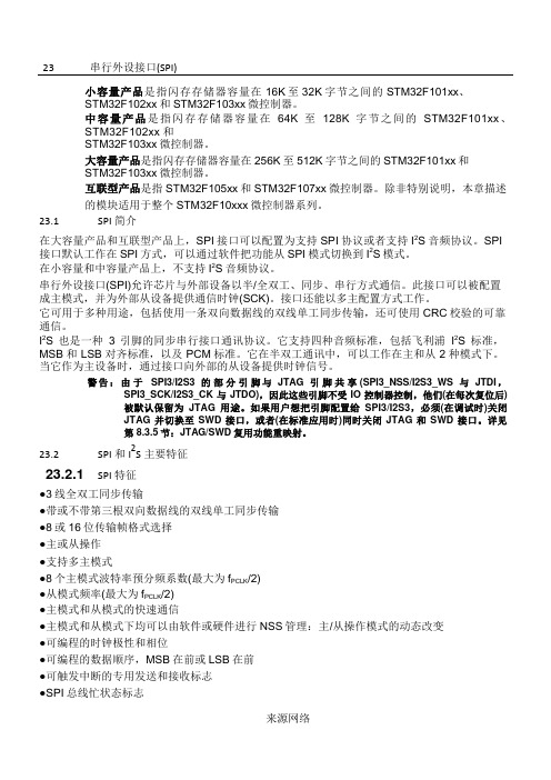
图210单主和单从应用
1.这里NSS引脚设置为输入
MOSI脚相互连接,MISO脚相互连接。这样,数据在主和从之间串行地传输(MSB位在前)。
通信总是由主设备发起。主设备通过MOSI脚把数据发送给从设备,从设备通过MISO引脚回传数据。这意味全双工通信的数据输出和数据输入是用同一个时钟信号同步的;时钟信号由主设备通过SCK脚提供。
读SPI_DR寄存器时,RXNE位被清除。
23.3.3配置SPI为主模式
在主配置时,在SCK脚产生串行时钟。
配置步骤
1.通过SPI_CR1寄存器的BR[2:0]位定义串行时钟波特率。
2.选择CPOL和CPHA位,定义数据传输和串行时钟间的相位关系(见图212)。
3.设置DFF位来定义8位或16位数据帧格式。
●支持DMA功能的1字节发送和接收缓冲器:产生发送和接受请求
23.2.2I2S功能
●单工通信(仅发送或接收)
●主或者从操作
●8位线性可编程预分频器,获得精确的音频采样频率(8KHz到96kHz)
●数据格式可以是16位,24位或者32位
●音频信道固定数据包帧为16位(16位数据帧)或32位(16、24或32位数据帧)
数据发送过程
在写操作中,数据字被并行地写入发送缓冲器。
当从设备收到时钟信号,并且在MOSI引脚上出现第一个数据位时,发送过程开始(译注:此时第一个位被发送出去)。余下的位(对于8位数据帧格式,还有7位;对于16位数据帧格式,还有15位)被装进移位寄存器。当发送缓冲器中的数据传输到移位寄存器时,SPI_SP寄存器的TXE标志被设置,如果设置了SPI_CR2寄存器的TXEIE位,将会产生中断。
请按照以下步骤配置SPI为从模式:
STM32-参考手册-中文.pdf
STM32-参考⼿册-中⽂.pdf23 串⾏外设接⼝(SPI)⼩容量产品是指闪存存储器容量在16K ⾄32K 字节之间的STM32F101xx、STM32F102xx和STM32F103xx微控制器。
中容量产品是指闪存存储器容量在64K⾄128K字节之间的STM32F101xx、STM32F102xx和STM32F103xx微控制器。
⼤容量产品是指闪存存储器容量在256K⾄512K字节之间的STM32F101xx和STM32F103xx微控制器。
互联型产品是指STM32F105xx和STM32F107xx微控制器。
除⾮特别说明,本章描述的模块适⽤于整个STM32F10xxx微控制器系列。
23.1 SPI简介在⼤容量产品和互联型产品上,SPI接⼝可以配置为⽀持SPI协议或者⽀持I2S⾳频协议。
SPI接⼝默认⼯作在SPI⽅式,可以通过软件把功能从SPI模式切换到I2S模式。
在⼩容量和中容量产品上,不⽀持I2S⾳频协议。
串⾏外设接⼝(SPI)允许芯⽚与外部设备以半/全双⼯、同步、串⾏⽅式通信。
此接⼝可以被配置成主模式,并为外部从设备提供通信时钟(SCK)。
接⼝还能以多主配置⽅式⼯作。
它可⽤于多种⽤途,包括使⽤⼀条双向数据线的双线单⼯同步传输,还可使⽤CRC校验的可靠通信。
I2S也是⼀种3引脚的同步串⾏接⼝通讯协议。
它⽀持四种⾳频标准,包括飞利浦I2S标准,MSB 和LSB对齐标准,以及PCM标准。
它在半双⼯通讯中,可以⼯作在主和从2种模式下。
当它作为主设备时,通过接⼝向外部的从设备提供时钟信号。
警告:由于 SPI3/I2S3 的部分引脚与 JTAG 引脚共享 (SPI3_NSS/I2S3_WS 与 JTDI ,SPI3_SCK/I2S3_CK与JTDO),因此这些引脚不受IO控制器控制,他们(在每次复位后)被默认保留为JTAG⽤途。
如果⽤户想把引脚配置给SPI3/I2S3,必须(在调试时)关闭JTAG并切换⾄SWD接⼝,或者(在标准应⽤时)同时关闭JTAG和SWD接⼝。
第1章 STM32F10X系统介绍

• • • • •
多达2个 同步串行接口(18兆位 多达 个SPI同步串行接口 兆位 秒) 同步串行接口 兆位/秒 CAN 接口 接口(2.0B 主动 主动) USB 2.0 全速接口 调试模式 串行线调试(SWD)和JTAG接口 串行线调试 和 接口
1.1.4 STM32F10X 的应用前景
销售终端机 安防设备
• 72MHz CortexTM-M3 CPU
512 K
384 K
– 6KB to 64KB SRAM – Two lines: Performance and Access – FULL compatibility across family
256 K
128 K
STM32F103CB STM32F101CB STM32F103T8 STM32F103C8 STM32F101C8 STM32F103C6 STM32F101C6 48 pins LQFP
银行卡读卡器 超市收银机 扫描仪 报警系统 控制面板
USB 设备
生物认证和安全设备 读卡器
医药卫生
监护仪 检测设备
其它 工业自动化
程序控制器 工业网络 电池管理 ……
消费电子
PC附属设备 数码相机、GPS导航仪 卫星电话
强大的工具支持
Compilers and IDE Device Programming
– 16位处理器 位处理器 – 最高40MHz 最高
• 存储器
– 从32K字节至 字节至128K字节闪存 字节闪存 字节至 程序存储器 – 从6K字节至 字节至20K字节 字节SRAM 字节至 字节 – 多重自举功能
• 存储器
– 32K字节 字节 – SRAM:2K : – 只能从FLASH启动 只能从 启动
STM32F10xxx闪存编程参考手册

STM32F10xxx闪存编程手册
页1/22
依据2008年9月英文第4版翻译。本译文仅供参考,如有翻译错误,请以英文原稿为准
目录
1 概述 ...................................................................................................................................................4 1.1 特性 ........................................................................................................................................4 1.2 闪存模块组织 ...............................................................................................4
z Cortex-M3内核集成了两个调试端口: − JTAG调试接口(JTAG-DP)提供基于JTAG(Joint Test Action Group 联合测试行动 小组)协议的5线标准接口。 − SWD调试接口(SWD-DP)提供基于SWD(Serial Wire Debug 串行线调试)协议的2 线标准接口。
z 中容量产品是指闪存存储器容量在64K至128K字节之间的STM32F101xx、STM32F102xx 和STM32F103xx微控制器。
z 大 容 量 产 品 是 指 闪 存 存 储 器 容 量 在 256K 至 512K 字 节 之 间 的 STM32F101xx 和 STM32F103xx微控制器。
STM32F10x闪存编程手册_V6

3 寄存器说明 ......................................................................................................................................15 3.1 闪存访问控制寄存器(FLASH_ACR)......................................................................................15 3.2 FPEC键寄存器(FLASH_KEYR) ............................................................................................16 3.3 闪存OPTKEY寄存器(FLASH_OPTKEYR) ............................................................................16 3.4 闪存状态寄存器(FLASH_SR)................................................................................................16 3.5 闪存控制寄存器(FLASH_CR) ...............................................................................................17 3.6 闪存地址寄存器(FLASH_AR)................................................................................................18 3.7 选项字节寄存器(FLASH_OBR).............................................................................................18 3.8 写保护寄存器(FLASH_WRPR) .............................................................................................19 3.9 闪存寄存器映像 ....................................................................................................................19
STM32的FLASH存储器

关于STM32的FLASH操作说到STM32的FLSAH,我们的第一反应是用来装程序的,实际上,STM32的片内FLASH不仅用来装程序,还用来装芯片配置、芯片ID、自举程序等等。
当然,FLASH还可以用来装数据。
FLASH分类根据用途,STM32片内的FLASH分成两部分:主存储块、信息块。
主存储块用于存储程序,我们写的程序一般存储在这里。
信息块又分成两部分:系统存储器、选项字节。
系统存储器存储用于存放在系统存储器自举模式下的启动程序(BootLoader),当使用ISP方式加载程序时,就是由这个程序执行。
这个区域由芯片厂写入BootLoader,然后锁死,用户是无法改变这个区域的。
选项字节存储芯片的配置信息及对主存储块的保护信息。
FLASH的页面STM32的FLASH主存储块按页组织,有的产品每页1KB,有的产品每页2KB。
页面典型的用途就是用于按页擦除FLASH。
从这点来看,页面有点像通用FLASH的扇区。
STM32产品的分类STM32根据FLASH主存储块容量、页面的不同,系统存储器的不同,分为小容量、中容量、大容量、互联型,共四类产品。
小容量产品主存储块1-32KB,每页1KB。
系统存储器2KB。
中容量产品主存储块64-128KB,每页1KB。
系统存储器2KB。
大容量产品主存储块256KB以上,每页2KB。
系统存储器2KB。
互联型产品主存储块256KB以上,每页2KB。
系统存储器18KB。
对于具体一个产品属于哪类,可以查数据手册,或根据以下简单的规则进行区分:STM32F101xx、STM32F102xx、STM32F103xx产品,根据其主存储块容量,一定是小容量、中容量、大容量产品中的一种,STM32F105xx、STM32F107xx是互联型产品。
互联型产品与其它三类的不同之处就是BootLoader的不同,小中大容量产品的BootLoader只有2KB,只能通过USART1进行ISP,而互联型产品的BootLoader有18KB,能通过USAT1、4、CAN等多种方式进行ISP。
STM32参考手册中文.pdf
口册23 串行外设接口(SPI)小容量产品是指闪存存储器容量在16K 至32K 字节之间的STM32F101xx、STM32F102xx和STM32F103xx微控制器。
中容量产品是指闪存存储器容量在64K至128K字节之间的STM32F101xx、STM32F102xx 和STM32F103xx微控制器。
大容量产品是指闪存存储器容量在256K至512K字节之间的STM32F101xx和STM32F103xx微控制器。
互联型产品是指STM32F105xx和STM32F107xx微控制器。
除非特别说明,本章描述的模块适用于整个STM32F10xxx微控制器系列。
23.1 SPI简介在大容量产品和互联型产品上,SPI接口可以配置为支持SPI协议或者支持I2S音频协议。
SPI接口默认工作在SPI方式,可以通过软件把功能从SPI模式切换到I2S模式。
在小容量和中容量产品上,不支持I2S音频协议。
串行外设接口(SPI)允许芯片与外部设备以半/全双工、同步、串行方式通信。
此接口可以被配置成主模式,并为外部从设备提供通信时钟(SCK)。
接口还能以多主配置方式工作。
它可用于多种用途,包括使用一条双向数据线的双线单工同步传输,还可使用CRC校验的可靠通信。
I2S也是一种3引脚的同步串行接口通讯协议。
它支持四种音频标准,包括飞利浦I2S标准,MSB 和LSB对齐标准,以及PCM标准。
它在半双工通讯中,可以工作在主和从2种模式下。
当它作为主设备时,通过接口向外部的从设备提供时钟信号。
警告:由于SPI3/I2S3 的部分引脚与JTAG 引脚共享(SPI3_NSS/I2S3_WS 与JTDI ,SPI3_SCK/I2S3_CK与JTDO),因此这些引脚不受IO控制器控制,他们(在每次复位后) 被默认保留为JTAG用途。
如果用户想把引脚配置给SPI3/I2S3,必须(在调试时)关闭JTAG并切换至SWD接口,或者(在标准应用时)同时关闭JTAG和SWD接口。
stm32f100编程手册
stm32f100编程手册
STM32F100编程手册是一份详细的文档,提供了关于
STM32F100微控制器的编程和使用指南。
这份手册通常包括以下内容:
1.概述:介绍STM32F100系列微控制器的基本特点和应用领域。
2.硬件架构:详细描述STM32F100微控制器的硬件架构,包括引脚配
置、内部模块、存储器等。
3.软件开发工具:介绍用于开发STM32F100微控制器的软件开发工具,
如编译器、调试器、烧录器等。
4.外设模块:详细介绍STM32F100微控制器内部的各种外设模块,如
GPIO、UART、SPI、I2C等,包括其工作原理、寄存器配置和使用方法。
5.中断和事件处理:描述STM32F100微控制器的中断和事件处理机制,
包括中断源、优先级和向量表等。
6.编程语言和开发环境:介绍常用的编程语言(如C语言)和开发环
境(如Keil、IAR等),以及如何在这些环境中编写和调试STM32F100微控制器的程序。
7.示例程序:提供一些示例程序,演示如何使用STM32F100微控制器
的各种功能模块。
8.应用案例:介绍一些实际应用案例,展示STM32F100微控制器在各
个领域的应用。
9.参考手册和数据表:提供STM32F100微控制器的参考手册和数据表,
以便读者深入了解其详细规格和性能参数。
总之,STM32F100编程手册是一份全面、实用的参考资料,旨在帮助开发者快速掌握STM32F100微控制器的使用和编程技巧。
通过阅读这份手册,开发者可以更好地理解STM32F100系列微控制器的功能特点和使用方法,从而更有效地进行相关应用开发。
STM32F40xxxF41xxx闪存编程手册c
2
版本历史 . . . . . . . . . . . . . . . . . . . . . . . . . . . . . . . . . . . . . . . . . . . . . . . . . . 24
2/25
文档 ID 018520 第 1 版
PM0081
表格索引
表格索引
表 1. 表 2. 表 3. 表 4. 表 5. 表 6. 表 7. 表 8.
1.4 读接口 . . . . . . . . . . . . . . . . . . . . . . . . . . . . . . . . . . . . . . . . . . . . . . . . . . . . 8 1.4.1 CPU 时钟频率与 Flash 读取时间之间的关系 . . . . . . . . . . . . . . . . . . . . . . 8 1.4.2 自适应实时存储器加速器 (ART Accelerator™) . . . . . . . . . . . . . . . . . . . . 9
Flash 模块构成 . . . . . . . . . . . . . . . . . . . . . . . . . . . . . . . . . . . . . . . . . . . . . . . . . . . . . . . . . . . 7 CPU 时钟 (HCLK) 频率对应的等待周期数 (VOS = ‘1’) . . . . . . . . . . . . . . . . . . . . . . . . . . . . . 8 编程 / 擦除并行位数 . . . . . . . . . . . . . . . . . . . . . . . . . . . . . . . . . . . . . . . . . . . . . . . . . . . . . . . 12 选项字节构成 . . . . . . . . . . . . . . . . . . . . . . . . . . . . . . . . . . . . . . . . . . . . . . . . . . . . . . . . . . . 14 关于选项字节的说明 . . . . . . . . . . . . . . . . . . . . . . . . . . . . . . . . . . . . . . . . . . . . . . . . . . . . . . 14 OTP 区域构成 . . . . . . . . . . . . . . . . . . . . . . . . . . . . . . . . . . . . . . . . . . . . . . . . . . . . . . . . . . . 17 Flash 寄存器映射与复位值 . . . . . . . . . . . . . . . . . . . . . . . . . . . . . . . . . . . . . . . . . . . . . . . . . 23 文档版本历史 . . . . . . . . . . . . . . . . . . . . . . . . . . . . . . . . . . . . . . . . . . . . . . . . . . . . . . . . . . . 24
stm32---->总线架构

stm32---->总线架构在了解stm32系列产品前,我们需要了解什么叫⼩容量、中容量、⼤容量产品。
顾名思义,容量即标志着⼀个物体装置着多少东西,对于stm32⽽⾔,存储器的⼤⼩就标志着它容量的⼤⼩。
⼩容量产品:指闪存存储器容量在16K⾄32K字节之间的STM32F101xx、STM32F102xx和 STM32F103xx微控制器。
中容量产品:指闪存存储器容量在在64K⾄128K字字节之间的STM32F101xx、STM32F102xx和 STM32F103xx微控制器。
⼤容量产品:指闪存存储器容量在256K⾄512K字节之间的STM32F101xx、STM32F102xx和 STM32F103xx微控制器。
总线架构在⼩容量、中容量、⼤容量产品中,主系统有下图所⽰:接下来,我们对不同部分做出分析:Cortex-M3是stm32的内核,也就是我们俗称的中央处理器cpu,CM3 采⽤了哈佛结构,拥有独⽴的指令总线和数据总线,指令总线和数据总线共享同⼀个存储器空间4G。
上图可以看到的是,它联络着三条总线,分别是ICode、DCode、SyStem。
I-Code 总线是⼀条基于AHB-Lite 总线协议的 32 位总线,负责在 0x0000_0000 – 0x1FFF_FFFF 之间的取指操作。
取指以字的长度执⾏,即使是对于 16 位指令也如此。
因此 CPU 内核可以⼀次取出两条 16 位 Thumb 指令。
D-Code 总线也是⼀条基于 AHB-Lite 总线协议的 32 位总线,负责在0x0000_0000 – 0x1FFF_FFFF之间的数据访问操作。
尽管 CM3⽀持⾮对齐访问,但你绝不会在该总线上看到任何⾮对齐的地址,这是因为处理器的总线接⼝会把⾮对齐的数据传送都转换成对齐的数据传送。
因此,连接到 D-Code总线上的任何设备都只需⽀持 AHB-Lite 的对齐访问,不需要⽀持⾮对齐访问。
系统总线也是⼀条基于 AHB-Lite 总线协议的 32 位总线,负责在0x2000_0000 – 0xDFFF_FFFF 和0xE010_0000–0xFFFF_FFFF 之间的所有数据传送,取指和数据访问都算上。
- 1、下载文档前请自行甄别文档内容的完整性,平台不提供额外的编辑、内容补充、找答案等附加服务。
- 2、"仅部分预览"的文档,不可在线预览部分如存在完整性等问题,可反馈申请退款(可完整预览的文档不适用该条件!)。
- 3、如文档侵犯您的权益,请联系客服反馈,我们会尽快为您处理(人工客服工作时间:9:00-18:30)。
UM0462User manualSTM32™ and STM8™Flash loader demonstratorIntroductionThe purpose of this document is to describe the STMicroelectronics STM32™ and STM8™Flash loader demonstrator application that was developed to illustrate the System memoryboot loader capabilities.This document details the prerequested hardware and software environments, as well asthe use cases of the demonstrator software.November 2009Doc ID 13916 Rev 71/25Contents UM0462 Contents1Getting started . . . . . . . . . . . . . . . . . . . . . . . . . . . . . . . . . . . . . . . . . . . . . . 51.1Package contents . . . . . . . . . . . . . . . . . . . . . . . . . . . . . . . . . . . . . . . . . . . . 51.1.1Software contents . . . . . . . . . . . . . . . . . . . . . . . . . . . . . . . . . . . . . . . . . . 51.1.2Hardware contents . . . . . . . . . . . . . . . . . . . . . . . . . . . . . . . . . . . . . . . . . . 51.2System requirements . . . . . . . . . . . . . . . . . . . . . . . . . . . . . . . . . . . . . . . . . 51.3Flash loader demonstrator installation . . . . . . . . . . . . . . . . . . . . . . . . . . . . 71.3.1Software installation . . . . . . . . . . . . . . . . . . . . . . . . . . . . . . . . . . . . . . . . . 71.3.2Hardware installation . . . . . . . . . . . . . . . . . . . . . . . . . . . . . . . . . . . . . . . . 9 2User interface description . . . . . . . . . . . . . . . . . . . . . . . . . . . . . . . . . . . 10 3Command-line usage . . . . . . . . . . . . . . . . . . . . . . . . . . . . . . . . . . . . . . . 20 4Revision history . . . . . . . . . . . . . . . . . . . . . . . . . . . . . . . . . . . . . . . . . . . 242/25 Doc ID 13916 Rev 7UM0462List of tables List of tablesTable 1.Document revision history . . . . . . . . . . . . . . . . . . . . . . . . . . . . . . . . . . . . . . . . . . . . . . . . . 24Doc ID 13916 Rev 73/25List of figures UM0462 List of figuresFigure 1.System Properties dialog box. . . . . . . . . . . . . . . . . . . . . . . . . . . . . . . . . . . . . . . . . . . . . . . . 6 Figure 2.Device Manager window. . . . . . . . . . . . . . . . . . . . . . . . . . . . . . . . . . . . . . . . . . . . . . . . . . . . 7 Figure 3.InstallShield Wizard . . . . . . . . . . . . . . . . . . . . . . . . . . . . . . . . . . . . . . . . . . . . . . . . . . . . . . . 8 Figure 4.InstallShield Wizard license agreement . . . . . . . . . . . . . . . . . . . . . . . . . . . . . . . . . . . . . . . . 8 Figure 5.Connection settings page. . . . . . . . . . . . . . . . . . . . . . . . . . . . . . . . . . . . . . . . . . . . . . . . . . 11 Figure 6.Flash status page. . . . . . . . . . . . . . . . . . . . . . . . . . . . . . . . . . . . . . . . . . . . . . . . . . . . . . . . 12 Figure 7.Device information page - STM32 example . . . . . . . . . . . . . . . . . . . . . . . . . . . . . . . . . . . . 13 Figure 8.Device information page - STM8 example . . . . . . . . . . . . . . . . . . . . . . . . . . . . . . . . . . . . . 14 Figure 9.Operation choice page for STM32 . . . . . . . . . . . . . . . . . . . . . . . . . . . . . . . . . . . . . . . . . . . 16 Figure 10.Operation choice page for STM8 . . . . . . . . . . . . . . . . . . . . . . . . . . . . . . . . . . . . . . . . . . . . 17 Figure 11.Option byte edition page. . . . . . . . . . . . . . . . . . . . . . . . . . . . . . . . . . . . . . . . . . . . . . . . . . . 18 Figure 12.Operation progress page . . . . . . . . . . . . . . . . . . . . . . . . . . . . . . . . . . . . . . . . . . . . . . . . . . 19 Figure mand-line version . . . . . . . . . . . . . . . . . . . . . . . . . . . . . . . . . . . . . . . . . . . . . . . . . . . . 20 4/25 Doc ID 13916 Rev 7UM0462Getting started Doc ID 13916 Rev 75/251 Getting started1.1 Package contentsThe following items are supplied in the Flash loader demonstrator package:1.1.1 Software contents1. STBLLIB.dll : a dynamic-link library implementing the system memory boot loaderprotocol and the communication APIs as virtual functions to be loaded dynamicallyfrom the STUARTBLLib dll file.2. STUARTBLLib.dll : a dynamic-link library implementing the system memory boot loaderprotocol and the RS232 COM communication APIs.3. Files.dll : a dynamic-link library implementing the needed file manipulation APIs to loadand store binary, hexadecimal and motorola S19 files.4. STMicroelectronics Flash loader.exe: a wizard application that provides the high-leveloperations that can be performed by the user.5. STMFlashLoader.exe : a command-line version of the STMicroelectronics Flashloader.exe that provides the same features over several options.6. The “Map” directory is located in the installation directory. It contains the mappingdescription files of the supported devices.7. The “Src” directory is located in the installation directory. It contains the header and Libfiles of the two DLLs and the complete source of the command-line version.8.The “Doc” directory is located in the installation directory, it contains the UM0462 andUM0516 (Windows API for STMicroelectronics microcontroller boot loaders ) usermanuals.1.1.2 Hardware contentsThe Flash loader demonstrator is designed to work with all STMicroelectronics devices thatsupport the system memory boot mode UART protocol. For more details, please visit theSTMicroelectronics website ( ).1.2 System requirementsIn order to use the Flash loader demonstrator with the Windows operating system, a recentversion of Windows, such as Windows 98, Millennium, 2000, XP , Vista or Windows7 must beinstalled on the PC.The version of the Windows OS installed on your computer may be determined by right-clicking on the “My Computer” icon on the desktop, then clicking on the “Properties” item inthe displayed pop-up menu. The OS type is displayed in the “System Properties” dialog boxunder the “System” label as shown in Figure 1.Getting started UM0462 Figure 1.System Properties dialog boxFor communication purposes, you need to verify that you have an available COM port(RS232) if the application implements the UART interface.To check that you have an available interface (COM), right-click on the “My Computer” iconon the desktop and select “Properties” from the pop-up menu. The “System Properties”dialog box appears. Click on the “Hardware” tab, and then on the “Device manager” buttonto display the system hardware configuration. Available COM ports are grouped under the“Ports (COM & LPT)” node in the hardware tree as shown in Figure2.6/25 Doc ID 13916 Rev 7UM0462Getting startedDoc ID 13916 Rev 77/25Figure 2.Device Manager window It is interesting to know the capabilities of the COM port. To find out, right click on theCommunication Port (COMx) item then click on “Properties” to display the Propertieswindow. Select the “Port Settings” tab, then click on the arrow next to the “Bits per second”combo box to know the baud rates supported by the port.1.3 Flash loader demonstrator installation1.3.1 Software installationIf an older version is installed on you computer, remove it by using the “Add or RemovePrograms” service in the “Control Panel”.Run the provided Setup.exe file: the InstallShield Wizard will guide you through theinstallation of the Flash loader demonstrator application on your computer as shown inFigure 3 and Figure 4 (Y ou must accept the license agreement to install the software).Getting started UM0462 Figure 3.InstallShield WizardFigure 4.InstallShield Wizard license agreementOnce the software has been successfully installed, click on the “Finish” button. Theversion.txt file containing the new release notes will automatically open in the Microsoft®-native Notepad application. Closing Notepad will launch the Flash loader demonstrator if thecheck boxes are kept as default in the InstallShield Wizard.8/25 Doc ID 13916 Rev 7UM0462Getting startedDoc ID 13916 Rev 79/251.3.2 Hardware installationAs the Flash loader demonstrator is able to communicate over the UART interface, thedevice should be connected to a spare PC COM port in the event of a UARTcommunication.User interface description UM046210/25 Doc ID 13916 Rev 72 User interface descriptionThe Flash loader demonstrator is designed as a wizard application. It is structured into sixsteps, the:1.Connection settings page 2. Flash status page3.Device information page 4.Operation choice page 5.Option byte edition page 6. Operation progress page Step 1Run the Flash loader demonstrator application from the “Programs” menu (connection to thedevice has not been made yet) then, make sure that the device is connected to your PC andreset it to restart the system memory boot loader code.This step consists in selecting the UART connection interface and its related settings. Setthe connection settings (port name, baud rate and timeout, etc.) as shown in Figure 5. Foran optimum configuration for the UART interface, set “Baud Rate” to 115200 bits per secondand “Timeout(s)” to 5 seconds.Ensure that the boot configuration pins are set correctly, then click “Next” to continue. If aconnection has been established, the wizard moves to the next step, otherwise a messagebox is displayed that indicates the error that occurred.Possible errors messages:●“Cannot open the COM port”: this message is shown if the selected COM port is not found or if it is already being used by another process.●“Unrecognized device”: this message is shown if the received value is different from 0x79. Resetting the device may solve the problem.●“No response from the target”: this message is shown when there is no response from the target. It indicates that the System memory boot loader is not functional. Verify theboot configuration and check that the used microcontroller contains the boot loadercode.Note:The Timeout argument is the period of time after which a read request from the serial port isaborted if no data is received. The recommended value is 5 seconds, but it depends on theused environment, like the hardware performance.Figure 5.Connection settings pageNote:“Echo” combo-box is present in version 2.1.0 of the Flash loader demonstrator for the support of some STM8 devices that use LIN echo back emulation through the UARTprotocol. If these devices are not used, this option should be kept disabled.Doc ID 13916 Rev 711/25Step 2In the second step the connection has been established and communication has started. Itconsists in displaying the Flash memory status. This status can be read-protected, in whichcase the “Next” button is disabled until the read protection is removed by clicking on the“Remove protection” button.Note:Clicking on the “Remove protection” button will not only read-unprotect the Flash memory, it will also erase all its pages.Figure 6.Flash status page12/25 Doc ID 13916 Rev 7Step 3In this step the Wizard displays the available device information such as the target ID, the firmware version, the supported device, the memory map and the memory protection status. Select the target name in the target combobox as shown in Figure7 and Figure8, then click on “Next” to continue.Figure 7.Device information page - STM32 exampleDoc ID 13916 Rev 713/25Figure 8.Device information page - STM8 example14/25 Doc ID 13916 Rev 7Step 4At this step, select the requested operation –Erase, Download, Upload or Disable/Enable Flash protection or Edit option bytes – and set the related parameters:1.Erasea) Choose “All” to erase the whole memoryb) Choose “Selection” to customize the Erase operation. Click the “...” button todisplay the memory mapping dialog window. Then check the pages to be erasedand click “Ok”.2. Download–Click the related browse button to open a binary, hexadecimal or S19 Motorola file.If the loaded file is a binary file, the download address is the start address of thefirst page and the “@” field is still editable to accept changes.If the loaded file is a hexadecimal or an S19 motorola file, the download address isthe start address of the first record in the file, and the “@” field is read-only.–Check the “Verify” check box to launch the verification process when the Download operation is finished.–Check “Jump to the user program” to launch the downloaded program.–Check “Optimize” to filter FFs packets (256 bytes).–Check “Apply option bytes”, then browse the option byte file created by the “Edit option bytes” operation. The values in the selected file will be applied to the deviceafter download.3. Upload–Click the related browse button to select which binary, hexadecimal or S19 motorola file will store the uploaded data.4. Disable/Enable Flash protection–Select the choices from the two drop-down menus to make up the desired command (Enable Read protection, Disable Read protection, Enable Writeprotection, Disable Write protection). All protection commands will be applied to allthe Flash memory pages except for the Enable Write Protection, which can becustomized. This is done by clicking the “...” button to select the pages to be write-protected.5. Edit option bytes–If you need to set the option bytes, check the option then click “Next” to move to the option byte edition page (Step 5 Figure 11.).Warning:Erase and Download operations can be performed only if thewrite protection is disabled.Doc ID 13916 Rev 715/25Figure 9.Operation choice page for STM3216/25 Doc ID 13916 Rev 7Figure 10.Operation choice page for STM8Step 5Note:This step applies to STM32 devices only. There is no step 5 for STM8 devices.The last Wizard page depends on the operation selected in Step 4.a) Case of an “Edit option bytes” operation:The Option byte edition page is displayed. It contains the current option byte valuesloaded from the device: RDP, USER, Data0, Data1, WRP0, WRP1, WRP2 and WRP3.For more details, please refer to the Option byte loader section in the “STM32F10xxxFlash programming manual” (PM0042 available from ).This step gives the possibility of applying the edited option byte values, loading themfrom the device and saving them to a file.Doc ID 13916 Rev 717/25Figure 11.Option byte edition pageb) Case of any other operation:The operation page is shown. It gives the size of the data to be downloaded oruploaded, the percent completed and the duration of the operation as illustrated inFigure12.●If the operation is successful, the progress bar is green colored. If an error occurs, thebar turns red and the error is displayed.●To stop the operation click the “Cancel” button.●If the “Jump to the user program” check box was checked in the previous step (Step 4),and the user program was successfully downloaded, communication with the systemmemory boot loader is lost. Consequently, the “Back” button is redirected to the“Connection settings page” (Step 1) to avoid the launch of a new operation.If the “Jump to the user program” check box was not checked in Step 4, the “Back”button is still active and you can return to Step 4 and select a new operation.18/25 Doc ID 13916 Rev 7Figure 12.Operation progress pageDoc ID 13916 Rev 719/25Command-line usage UM046220/25 Doc ID 13916 Rev 73 Command-line usageThe command-line version (STMFlashLoader.exe ) provides the same functionality as theGUI. It supports several options in order to run a sequence of operations.The following paragraphs describe the available command-line options as shown inFigure 13.Figure mand-line versionSTMFlashLoader.exe option [Arguments] [option [Arguments]]...-?Shows help.-c:Defines the COM port.UM0462Command-line usage The -c option allows you to select the COM port that the command uses to communicatewith the target MCU. By default, the command uses COM1. T o select different COM portand connection settings, use the -c option in the form:-c--pn port_number (e.g 1, 2..., default 1)-c --br baud_rate (e.g 115200, 57600..., default 57600)-c--db data_bits (value in {5,6,7,8}..., default 8)-c--pr parity (value in {NONE,ODD,EVEN}..., default EVEN)-c--sb stop_bits (value in {1,1.5,2}..., default 1)-c--ec echo (value ON or OFF..., default is OFF)-c--to time_out ((ms) e.g 1000, 2000, 3000..., default 5000)The -c option supports multiple arguments. This means that you can set more than oneargument in the same command:-c --pn 1 --br 115200 --to 7000-i device_nameDefines the MCU target to be used.For example: STM8_32K, STM32_Med-density_128K, STM32_High-density_512K,STM32_Low-density_16K etc. The device name is the name of the map file located in theMap directory.-eErase command.According to the given arguments, the command can be used to erase a specific page ofmemory or, to erase the entire Flash memory. This operation can take a second or more tocomplete, depending on the memory size involved.-e --all erase all pages-e --sec number_of_pages_group pages_group_codes-e --sec 3 0 1 2 erases 3 groups of pages coded 0, 1 and 2-uUploads the Flash memory contents to the specified file (bin, hex or s19 file; the file type isrecognized by its extension), to specify a file use the -u option in the form:-u --fn file_name (full path name)-dDownloads the contents of the specified file into the MCU Flash memory at the specifiedaddress. To specify the file to be downloaded and the download address, use the -d optionin the form:-d --a address(hex) --fn file_name (full path name (bin, hex or s19 file); the file type isrecognized by its extension).The address is mandatory in the case of binary files and ignored in the case of hex and s19files.To verify the downloaded data, add the --v argument.To optimize and remove FF packets, use the --o argument.Doc ID 13916 Rev 721/25Command-line usage UM0462-oGets or sets option bytes.Use --get to read option bytes from the device and store values to a file.--get --fn file_name (full path name)Use --set to write option bytes to the device. The option bytes can be read from a file orgiven as values.--set --fn file_name (full path name)--set --vals --OPB hex_value (OPB in (User, RDP, Data0, Data1, WRP0, WRP1,WRP2, WRP3).The -o option can accept multiple arguments as shown below:-o --get get_file_name --set set_file_name-o --get get_file_name --set --vals --User 01 --RDP 5A --Data0 DE --Data1 EAWarning:When setting option bytes, if RDP is not equal to A5h, theread protection is activated, and all subsequent operationswill fail.22/25 Doc ID 13916 Rev 7UM0462Command-line usage-pActivates or deactivates the protection. It is used as shown below:-p --erp (Activate read protection)-p --drp (Deactivate read protection)-p --ewp number_of_pages_group pages_group_codes (activates the write protectionon the given page group codes)-p --dwp (disables the write protection)Warning:The --erp argument activates the read protection. Allsubsequent operations will fail. To avoid this kind of problem,use -p --erp as the last argument.-rPerforms a jump to the specified address. It is used as follows:-r --a address(hex)-RtsSets the COM RTS pin to either high or low level. It is used as follows:-Rts -- Hi-DtrSets the COM DTR pin to either high or low level. It is used as follows:-Dtr -- LoNote:Note that all command-line options found are executed IN ORDER. Thus, with a careful arrangement of the command-line options, you can perform a complicated sequence ofoperations using custom batch files.Doc ID 13916 Rev 723/25Revision history UM046224/25 Doc ID 13916 Rev 74 Revision historyTable 1.Document revision history DateRevision Changes 25-Oct-20071Initial release.05-Jun-20082Flash loader demonstrator version upgraded to V1.1.Small text changes.Section 1.1.1: Software contents updated. Section 1.2: Systemrequirements modified.Welcome step removed, Flash status page and Option byte editionpage added.Section 3: Command-line usage added.Step 2 on page 12 added. Step 5 on page 17 modified.17-Jun-20083Software revision updated in Section 1.3.1: Software installation onpage 7.31-Oct-20084Flash loader demonstrator version upgraded to V1.2. It can also beused with STM8 devices.Figure 5 to Figure 12 updated accordingly.04-Mar-20095Flash loader demonstrator version upgraded to V1.3. Figure 5 toFigure 12 updated accordingly.02-Jul-20096Flash loader demonstrator version upgraded to V2.0. This versionapplies not only to the STM32™ family but also to the STM8™ family.Section 1.1.1: Software contents updated (STUARTBLLib.dll andSTCANBLLib.dll added).Section 1.2: System requirements modified, Figure 2: DeviceManager window changed.Section 1.3.1: Software installation and Section 1.3.2: Hardwareinstallation updated.Step 1 and Figure 5: Connection settings page updated. Small textchanges.12-Nov-20097Flash loader demonstrator version upgraded to V2.1.0. Figure 1 toFigure 13 updated accordingly.Flash loader demonstrator is upgraded to support only UARTprotocol for STM8™ and STM32™ families.UM0462Please Read Carefully:Information in this document is provided solely in connection with ST products. STMicroelectronics NV and its subsidiaries (“ST”) reserve the right to make changes, corrections, modifications or improvements, to this document, and the products and services described herein at any time, without notice.All ST products are sold pursuant to ST’s terms and conditions of sale.Purchasers are solely responsible for the choice, selection and use of the ST products and services described herein, and ST assumes no liability whatsoever relating to the choice, selection or use of the ST products and services described herein.No license, express or implied, by estoppel or otherwise, to any intellectual property rights is granted under this document. If any part of this document refers to any third party products or services it shall not be deemed a license grant by ST for the use of such third party products or services, or any intellectual property contained therein or considered as a warranty covering the use in any manner whatsoever of such third party products or services or any intellectual property contained therein.UNLESS OTHERWISE SET FORTH IN ST’S TERMS AND CONDITIONS OF SALE ST DISCLAIMS ANY EXPRESS OR IMPLIED WARRANTY WITH RESPECT TO THE USE AND/OR SALE OF ST PRODUCTS INCLUDING WITHOUT LIMITATION IMPLIED WARRANTIES OF MERCHANTABILITY, FITNESS FOR A PARTICULAR PURPOSE (AND THEIR EQUIVALENTS UNDER THE LAWS OF ANY JURISDICTION), OR INFRINGEMENT OF ANY PATENT, COPYRIGHT OR OTHER INTELLECTUAL PROPERTY RIGHT. UNLESS EXPRESSLY APPROVED IN WRITING BY AN AUTHORIZED ST REPRESENTATIVE, ST PRODUCTS ARE NOT RECOMMENDED, AUTHORIZED OR WARRANTED FOR USE IN MILITARY, AIR CRAFT, SPACE, LIFE SAVING, OR LIFE SUSTAINING APPLICATIONS, NOR IN PRODUCTS OR SYSTEMS WHERE FAILURE OR MALFUNCTION MAY RESULT IN PERSONAL INJURY, DEATH, OR SEVERE PROPERTY OR ENVIRONMENTAL DAMAGE. ST PRODUCTS WHICH ARE NOT SPECIFIED AS "AUTOMOTIVE GRADE" MAY ONLY BE USED IN AUTOMOTIVE APPLICATIONS AT USER’S OWN RISK.Resale of ST products with provisions different from the statements and/or technical features set forth in this document shall immediately void any warranty granted by ST for the ST product or service described herein and shall not create or extend in any manner whatsoever, any liability of ST.ST and the ST logo are trademarks or registered trademarks of ST in various countries.Information in this document supersedes and replaces all information previously supplied.The ST logo is a registered trademark of STMicroelectronics. All other names are the property of their respective owners.© 2009 STMicroelectronics - All rights reservedSTMicroelectronics group of companiesAustralia - Belgium - Brazil - Canada - China - Czech Republic - Finland - France - Germany - Hong Kong - India - Israel - Italy - Japan - Malaysia - Malta - Morocco - Philippines - Singapore - Spain - Sweden - Switzerland - United Kingdom - United States of AmericaDoc ID 13916 Rev 725/25。
