MOKIA5610说明书
Nprot 5610使用说明
Nprot 5610安装说明一:按原来接线方法将Nport 5610接上。
首先,将Nport 5610显示单元上的IP地址记下(如192.168.1.21),之后按照原有设备的接线方式将新Nport 5610装上。
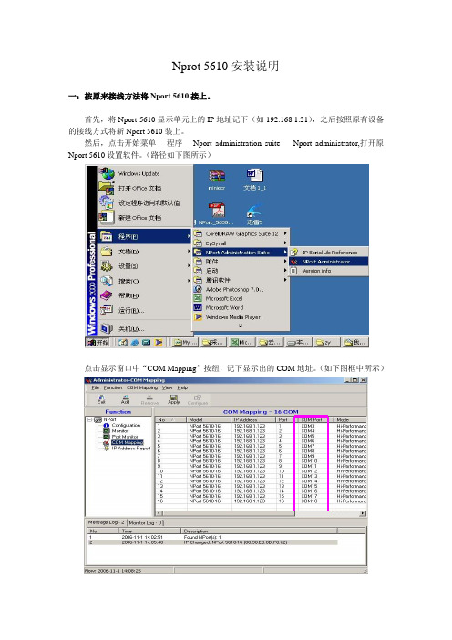
然后,点击开始菜单----程序----Nport administration suite-----Nport administrator,打开原Nport 5610设置软件。
(路径如下图所示)点击显示窗口中“COM Mapping”按纽,记下显示出的COM地址。
(如下图框中所示)二:卸载原软件点击开始菜单----设置----控制面板,双击“添加/删除程序”,找Nport软件,点击更改/删除。
(如下图所示)点击后在弹出对话框中选择“是”。
(如下图所示)点击后在弹出对话框中选择“YES TO ALL”。
(如下图所示)三:安装新Nport 5610 软件卸载完成后,将新光盘放到工控机光驱内,双击我的电脑----光盘盘符----Nport 5610----software----windows----npadm_setup_1.6.exe安装软件。
(如下图所示)出现安装界面后点击“NEXT”,出现选择路径界面。
(如下图所示)点击“NEXT”,出现程序名称界面(如下图所示)点击“NEXT”,出现如下图所示界面,点击“install”进行安装。
安装过程中如出现下图界面,请选择“否”。
等待出现完成界面后,点击“NEXT”。
(如下图所示)点击“Finish”。
结束安装。
(如下图所示)四:进入软件设置页面,进行软件设置安装完成后直接进入设置软件主界面。
(如下图所示)点击“search”,软件自动寻找设备。
(如下图所示)寻找结束后,会在主窗口显示Nport 5610设备。
此时,右键点击该设备,选择“Assign IP Access”,更改IP地址。
(如下图所示)将弹出窗口的“IP Address”下将IP改成先前记下的Nport 5610上的IP,(如下图粉框所示)之后点击“Assign IP Sequentially”更新IP地址,(如下图蓝框所示)之后点击“OK”确定。
湖北格泰QTZ63(5610)使用说明书
格泰GETAIQTZ63(5610)塔式起重机使用说明书格泰重工机械使用前请仔细阅读前言欢迎使用本公司产品。
请您在使用本机前详细阅读本说明书。
本说明书能帮助您正确有效的使用本机,创造最佳的经济效益,更重要的是能避免许多塔机故障和意外事故的发生。
说明:由于技术进步,塔机结构、性能的改进恕不另行通知。
注意:l、认真阅读、保管该产品说明书。
2、按照说明书中地耐力的要求制作塔机基础。
3、严禁非专业塔机安装人员安装、拆卸塔机,特别注意检查塔身标准节、支腿的各条焊缝,如有异常立即处理。
4、每次安装塔机前,必须认真检查、检修塔机。
5、每次转移工地安装塔机后,必须由当地有关部门验收后使用。
6、塔机司机必须持证上岗。
7、保证高度、幅度、重量、力矩限位器等安全装置正常工作。
8、严禁回转起重臂时反车制动。
9、严禁超风速工作。
10、严格执行GB5144《塔式起重机安全规程》ZBJ80012《塔式起重机操作使用规程》1l、钢丝绳断丝、断股、变形要及时更换。
12、按说明书要求定期检修。
目录1 概述 (1)2 起重机技术性能 (2)2.1技术性能参数表2.2配套机构明细表2.3起重性能表2.4起重特性曲线2.5供电参数3 起重机构造简述 (6)3.1总体布置3.2塔机固定式基础载荷及附着载荷3.3金属结构的主要外形尺寸及重量3.4工作机构3.5安全保护装置3.6电气控制与操纵系统3.7绕绳系统4 起重机的安装 (29)4.1组装注意事项4.2地基基础4.3接地装置4.4塔机组装过程5 安全保护装置及调试 (38)6 起重机的拆卸 (39)6.1拆卸注意事项6.2拆卸后的注意事项7 起重机的使用……………………………………………………………………………………4l 7.1投入使用前的工作7.2安全操作规程7.3维修及保养,每天上班前进行7.4主要故障及排除方法7.5其它8 附图、附表8.1整机零部件明细表 (50)8.2塔式起重机各部件润滑明细表8.3易损件明细表8.4轴承明细表8.5基础图8.6电气原理图1、概述QTZ63(5610)塔式起重机是格泰重工机械充分利用成组技术、组合设计技术及有限元分析技术,以“塔式起重机微机设计平台”为工具,设计的国最新型的起重运输机械。
摩尔克斯(Molex)小匹(Mini-Fit)BMI插座系列产品说明书

Mates With 15060240 Mini-Fit BMI Panel Mount Receptacle, 39012240 Mini-Fit Jr. Receptacle, 15247242 Mini-Fit BMI Vertical Receptacle Header
Plating min - Mating Plating min - Termination Polarized to Mating Part Polarized to PCB Shrouded Stackable Surface Mount Compatible (SMC) Temperature Range - Operating Termination Interface: Style
Series image - Reference only
Agency Certification CSA UL
General Product Family Series Application Comments
Comments
Overview Product Name UPC
Physical Breakaway Circuits (Loaded) Circuits (maximum) Color - Resin Durability (mating cycles max) Flammability Glow-Wire Capable Guide to Mating Part Lock to Mating Part Material - Metal Material - Plating Mating Material - Plating Termination Material - Resin Net Weight Number of Rows Orientation PC Tail Length PCB Locator PCB Retention PCB Thickness - Recommended Packaging Type Pitch - Mating Interface
中联重科TC5610塔吊说明书

中联重科TC5610塔吊说明书中联重科TC5610塔吊是一种用于建筑工程中的重型设备,在高大建筑物的建设中起着重要的作用。
本文将对这一设备的结构、原理、使用、维护等方面进行详细说明,以帮助使用者更好地了解和使用该设备。
一、结构中联重科TC5610塔吊的主要结构由底座、支撑臂、回转机构、起重机构、驾驶室等组成。
其中,底座为塔吊的基础,支撑臂通过底座与回转机构连接,在其一端安装起重机构,另一端为倾角传感器。
回转机构安装在支撑臂与底座之间,实现塔吊的旋转。
起重机构包括钩、卷扬机、拉绳、防倾柱等构件,用于吊装和移动物品。
驾驶室设置在回转机构下方,操作员可以通过控制台控制塔吊的运作。
二、原理中联重科TC5610塔吊的工作原理主要是通过电动机驱动卷扬机升降钩及货物,通过钢丝绳进行牵引力传递;同时通过电机带动回转机构进行回转,以实现吊运物品的定位;此外,塔吊配有倾角传感器,实时监测吊装时的倾斜度,并能将此信息通过控制台反馈给操作员,以保证工作安全。
三、使用方法1.选址在设置塔吊时,需要考虑承重能力和承载面积,选择充分承载塔吊的场地。
同时,在选择场地时还要考虑管线、电线杆等设施,确保塔吊运作不受阻碍。
2.组装在安装时,应按照说明书的步骤进行组装,确保组装质量;同时也需要注意安装过程中的安全,例如钢丝绳的正确接口和紧固等。
3.起吊在起吊过程中,需谨慎操作,确保吊装物品的平稳运输;同时注意倾斜度的监测,避免发生倒塌事故。
四、维护保养1.塔吊需要定期检查和维护,确保设备的正常使用。
2.检查钢丝绳和起重机构的接口是否牢固。
3.注意塔吊的润滑和清洁,避免因维护不当造成的故障。
综上所述,中联重科TC5610塔吊是一种重要的建筑工程设备,具有重要的作用。
在使用该设备时,需要了解其结构和原理,并通过正确的使用方法和维护保养,以确保塔吊的正常运行和工作安全,实现高效、安全的建筑施工。
5610说明书完整版中联版
TC5610B版QTZ80(TC5610)塔式起重机使用说明书致用户感谢您选购和使用本公司的塔式起重机!为了使您正确使用与维护该设备,操作前敬请仔细阅读本使用说明书,并妥善保管,以备查询。
本使用说明书中标有“注意:”的语句,涉及到施工的安全,敬请注意。
本公司致力于产品的不断完善,产品的某些局部结构或个别参数更改时,恕不另行通知。
如有疑问,请与本公司联系。
出厂编号:出厂日期:本公司致力于塔机的不断完善,满足用户的各种需求,随机文件变化频繁。
该编号的随机文件与该编号的主机一一对应,切忌混用!即使是同型号塔机,也不保证适用!目录概述.................................................... ........................ 0-1~0-8第一篇塔机的安装第一章立塔.......................................................... ~第二章拆塔.......................................................... ~第二篇塔机的使用与维护第一章塔机安全操作规程.................................... ~第二章机构及电气操作........................................ ~第三章安全保护装置.......................................... ~第四章保养与维修...............................................~附录一............................................... ..................... 1~7编制:校对:审核:概述TC5610 塔式起重机,是长沙中联重工科技发展股份有限公司按JG/T5037-93《塔式起重机分类》设计的。
ZT5610Z 中联使用说明书(10米连体统型)
中联重科塔吊TC5610-6说明书教程文件
中联重科塔吊tc56106说明书精品文档收集于网络如有侵权请联系管理员删除精品文档收集于网络如有侵权请联系管理员删除精品文档收集于网络如有侵权请联系管理员删除精品文档收集于网络如有侵权请联系管理员删除精品文档收集于网络如有侵权请联系管理员删除精品文档收集于网络如有侵权请联系管理员删除精品文系管理员删除精品文档收集于网络如有侵权请联系管理员删除精品文档收集于网络如有侵权请联系管理员删除精品文档收集于网络如有侵权请联系管理员删除精品文档收集于网络如有侵权请联系管理员删除精品文档收集于网络如有侵权请联系管理员删除精品文档收集于网络如有侵权请联系管理员删除精品文档收集于网络如有侵权请联系管理员删除精品文档收集于网络如有侵权请联系管理员删除精品文档收集于网络如有侵权请联系管理员删除精品文档收集于网络如有侵权请联系管理员删除精品文档收集于网络如有侵权请联系管理员删除精品文档收集于网络如有侵权请联系管理员删除精品文档收集于网络如有侵权请联系管理员删除精品文档收集于网络如有侵权请联系管理员删除精品文档收集于网络如有侵权请联系管理员删除精品文档收集于网络如有侵权请联系管理员删除精品文档收集于网络如有侵权请联系管理员删除精品文档收集于网络如有侵权请联系管理员删除精品文档收集于网络如有侵权请联系管理员删除精品文档收集于网络如有侵权请联系管理员删除精品文档收集于网络如有侵权请联系管理员删除精品文档收集于网络如有侵权请联系管理员删除精品文档收集于网络如有侵权请联系管理员删除精品文档收集于网络如有侵权请联系管理员删除精品文档收集于网络如有侵权请联系管理员删除精品文档收集于网络如有侵权请联系管理员删除精品文档收集于网络如有侵权请联系管理员删除精品文档收集于网络如有侵权请联系管理员删除精品文档收集于网络如有侵权请联系管理员删除精品文档收集于网络如有侵权请联系管理员删除精品文档收集于网络如有侵权请联系管理员删除精品文档收集于网络如有侵权请联系管理员删除精品文档收集于网络如有侵权请联系管理员删除精品文档收集于网络如有侵权请联系管理员删除精品文档收集于网络如有侵权请联系管理员删除精品文档收集于网络如有侵权请联系管理员删除精品文档收集于网络如有侵权请联系管理员删除精品文档收集于网络如有侵权请联系管理员删除精品文档收集于网络如有侵权请联系管理员删除精品文档收集于网络如有侵权请联系管理员删除
莫加 UC 系列产品说明书

Entry-level Arm-based 64-bit ComputersDual-core, 2-GB RAMCompact Dual-core, 2-GB RAM Built-in LTEValue-added Arm-based 64-bit ComputersQuad-core, 4-GB RAMQuad-core, 4-GB RAM5G/CAN/serial IsolationBuilt-in LTEMoxa Industrial LinuxMoxa's Debian-based industrial-grade stable Linux distribution for long-term projectsFeatures and Benefits5Debian-based distribution that can use all standard Debian packages5Developed as per IEC 62443-4-1 and compliant with IEC 62443-4-2 industrialcybersecurity standards (Moxa Industrial Linux 3 Secure)5Long-term support until 2027 for Moxa Industrial Linux 1 and 2031 for MoxaIndustrial Linux 35Wireless connection management utility with automatic network keep alive andfailover5Ready-to-use APIs and library to ease access to hardware and I/O interfaces5Crash-free robust file system5Over-the air (OTA) software updatesWireless-ready Arm-based 32-bit Computers Built-in cellular or Wi-Fi module, RF type approvals, and carrier approvalsBuilt-in LTE Cat.1Built-in LTECat.1 and Wi-FiBuilt-in LTECat.1 and Wi-FiBuilt-in LTECat.4 with Wi-Fi expansion1. Wireless module is built-in. Refer to the Wireless Connection and Expansion Modules section for details.2. Wireless module must be purchased separately. Refer to the Wireless Connection and Expansion Modules section for details.1 mPCIe for cellular/Wi-Fi1 mPCIe forcellular/Wi-Fi1 mPCIe forcellular/Wi-Fi1 mPCIe forcellular/Wi-Fi1 mPCIe for cellular 1mPCIe for Wi-Fi1 mPCIe forcellular/Wi-FiArm-based 32-bit Computers With Wireless Options Flexibility to add cellular or Wi-Fi capability when needed1. Wireless module must be purchased separately. Refer to the Wireless Connection and Expansion Modules section for details.1 LAN,1 serial2 LAN 2 LAN,2 serial2 LAN,2 serial2 LAN,4 serial2 LAN,4 serial2 LAN,1 serial2 LAN,2 serial3 LAN,8 serialStandard Arm-based 32-bit Computers Low power consumption and small form factorWireless Connectivity and Expansion Modules* Details of cellular and Wi-Fi support with a list of wireless accessory models* Antennas must be purchased separatelyLast updated: Aug. 15, 2023. All specifications are subject to change without notice.。
moxa_nport5610说明文档
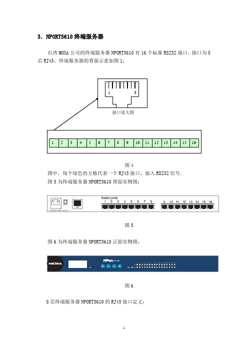
3.NPORT5610终端服务器台湾MOXA公司的终端服务器NPORT5610有16个标准RS232端口,接口为8芯RJ45。
终端服务器的背面示意如图1:1 8接口放大图1 2 3 4 5 6 7 8 9 10 11 12 13 14 15 16图4图中,每个绿色的方格代表一个RJ45接口,接入RS232信号。
图5为终端服务器NPORT5610背面实物图:图5图6为终端服务器NPORT5610正面实物图:图68芯终端服务器NPORT5610的RJ45接口定义:表43.1 使用方法NPort Server 5610终端服务器有两种使用方法,一种是在windows 操作系统的前置机上安装驱动程序,扩展串口,前置系统访问扩展的串口采用windows 提供的标准串口访问接口;另一种是在unix 或windows 操作系统的前置机不安装驱动程序,前置系统直接通过网络TCP 方式访问扩展的串口。
两种方式都可以,根据实际系统需要使用。
3.2硬件安装终端服务器的硬件安装过程为:步骤 1 按照通道柜配置图上终端服务器的位置将终端服务器安装在通道柜中,固定好。
2 用电缆连接线将终端服务器和通道机箱连接起来。
3.3 与通道机箱的连接终端服务器和通道机箱用双脚线连接,做线的长度根据实际长度测量,线两端的接头用RJ45水晶头。
下图为终端服务器和通道机箱的连接示意图:通道机箱终端服务器A双绞线图7图6中,通道机箱的两排接口,输出相同的数据信号,分别输入到A前置机的终端服务器和B前置机的终端服务器。
接线的顺序从1口至16口一一对应。
通道机箱RJ45定义表表5终端服务器和通道机箱用双脚线连接对应表:表63.4安装驱动程序和Administrator Configuration管理工具在设备接上计算机后,首先需要进行驱动程序和终端服务器管理工具的安装。
安装步骤如下:步骤 1:将MOXA公司提供的software cd光盘放入光驱中,一会计算机屏幕上会弹出如下图所示对话框,如果没有弹出所示对话框,可以直接运行光盘根目录下\Autorun\Launch.exe程序,也会弹出对话框:步骤2:单击INSTALL UTILITY按钮,弹出下图对话框:步骤3:单击“是”按钮步骤4:单击“Next>”按钮步骤5:选择或填写需要安装的路径,单击“Next>”按钮步骤6:单击“Next>”按钮步骤7:单击“Install”按钮,显示下图,程序正在安装步骤8:程序安装完成后将会显示下图对话框步骤9:单击“Next>”按钮步骤10:将Launch Nport Administrator前的勾去掉,单击“Finish”按钮,Nport5610驱动程序和管理工具安装完成。
TC5610中文说明书(起重臂拉杆按统型后配置)
出厂编号: 出厂日期:
本公司致力于塔机的不断完善, 满足 用户的各种需求,随机文件变化频繁。 该编号的随机文件与该编号的主机 一一对应, 切忌混用! 即使是同型号塔 机,也不保证适用!
目
录
概
述............................................................................ 0-1~0-8
第一篇 塔机的安装 第一章 第二章 立塔.......................................................... 1.1-1~1.1-32 拆塔.......................................................... 1.2-1~1.2-3
9.3.2 50m 起重特性表及起重特性曲线
R α=2 α=4 2.5~15 6.00 17 5.19 20 23 3.00 4.29 3.63 26 3.12 27.3 2.93 29 2.79 2.73 32 2.47 2.41 35 2.20 2.14 38 1.98 1.92 41 1.79 1.73 44 1.63 1.57 47 1.48 1.42 50 1.36 1.30
*TC5610-6-B
TC5610-6塔式起重机
概
述
0-2
9. 起重机的各项参数。 9.1 起重机整体技术参数.(表 9-1)
表 9-1
机构工作级别 公称起重力矩 kNm 起升高度 m 工作幅度 m 最大起重量 t 倍率 速度 m/min 起重量 t 功率 kW 牵引机构 回转机构 顶升机构 总功率 kW 平衡重
*TC5610-6-B
TC5610-6塔式起重机
徐州建机QTZ63_5610Fz-6_说明书封面
安装使用说明书徐工集团徐州建机工程机械有限公司致用户:感谢您选购和使用徐工集团徐州建机工程机械有限公司的塔式起重机产品。
为了使您正确使用与维护该设备,操作前敬请仔细阅读本使用说明书,并妥善保管,以备查询。
本使用说明书中标有“重要提示”、“注意”等语句,涉及到施工安全,敬请注意。
随着本公司依据国家新标准及新技术,新材料的不断采用、并不断致力于产品的完善,产品的某些局部结构或个别参数更改时,恕不另行通知!用户如有疑问,请与本公司联系。
用户购买产品最终以销售合同及发货配置为准。
生产编号:出厂日期:目录概述……………………………………………………… 0-1~8第一篇塔机的安装第一章立塔…………………………………………1-1~38第二章拆塔…………………………………………1-39~41第二篇塔机的使用与维护第一章塔机安全操作规程…………………………2-1~3第二章机构及电气操作…………………………… 2-4~8第三章安全保护装置………………………………2-9~12第四章保养与维修………………………………… 2-13~16第五章各类附表…………………………………… 2-17~18警示语……………………………………………………3-1~8塔机部件检查记录表……………………………………i~iii塔机部件润滑记录表…………………………………… A由于我公司产品在不断改进,本说明书将随之修改,我们将保留修改的权利。
产品识别代码(PIN)码(备注:产品上PIN码的位置在平衡臂右侧主弦杆臂根靠外侧)徐工集团塔式起重机安装使用说明书QTZ80概述QTZ80(5610Fz-6)塔式起重机,是徐州建机工程机械有限公司按照国家标准GB/T13752《塔式起重机设计规范》及JG/T5037《塔式起重机分类》研制的新一代塔式起重机。
QTZ80(5610-6)塔机为水平起重臂、小车变幅、上回转自升式多用途塔机,该机的特色有:1.性能参数及技术指标国内领先,最大工作幅度56m,最大起升高度140m。
QTZ5610塔机使用说明书
格林西格 gwo 5610 溶解氧传感器 使用说明书
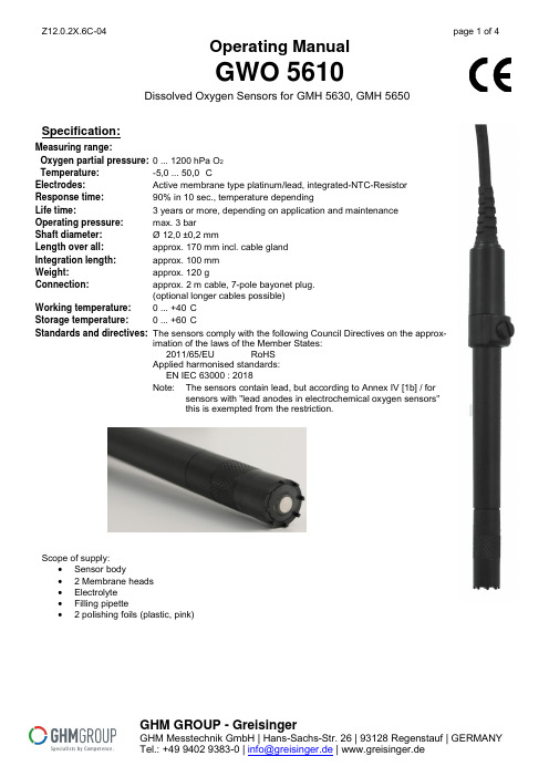
Operating ManualGWO 5610Dissolved Oxygen Sensors for GMH 5630, GMH 5650Specification:Measuring range:Oxygen partial pressure: 0 ... 1200 hPa O2Temperature:-5,0 ... 50,0 °CElectrodes:Active membrane type platinum/lead, integrated-NTC-ResistorResponse time:90% in 10 sec., temperature dependingLife time: 3 years or more, depending on application and maintenanceOperating pressure:max. 3 barShaft diameter:Ø 12,0 ±0,2 mmLength over all:approx. 170 mm incl. cable glandIntegration length:approx. 100 mmWeight:approx. 120 gConnection:approx. 2 m cable, 7-pole bayonet plug.(optional longer cables possible)Working temperature:0 ... +40°CStorage temperature: 0 ... +60°CStandards and directives:The sensors comply with the following Council Directives on the approx-imation of the laws of the Member States:2011/65/EU RoHSApplied harmonised standards:EN IEC 63000 : 2018Note: The sensors contain lead, but according to Annex IV [1b] / forsensors with "lead anodes in electrochemical oxygen sensors"this is exempted from the restriction.Scope of supply:∙Sensor body∙ 2 Membrane heads∙Electrolyte∙Filling pipette∙ 2 polishing foils (plastic, pink)GHM GROUP - GreisingerGHM Messtechnik GmbH | Hans-Sachs-Str. 26 | 93128 Regenstauf | GERMANYTel.: +49 9402 9383-0 | | www.greisinger.deDesign of Sensor GWO 5610Lifetime:At the end of the Lifetime, the signal of the sensor is dropping rapidly. The sensor evaluation in % therefore e can only be taken as a relative measure. An evaluation of 70% does not mean that 70% of lifetime is left, but that the electrode signal has 70% of a good state reference.Note: The sensor state evaluation will be stored after a successful calibration of the oxygen sensorThe nominal lifetime may be reduced due to the application. Negative effecting are:- Extreme storage and operation temperature- D irty water during measuring- Mechanical stress to sensor membrane- Dry storage of filled sensor- Permanent use at higher CO 2-concentrationsMounting/Operation Position:The optimum position is with sensor membrane pointing downwards.Measuring Precision: The precision can be influenced due to:- To less flow- Water and sensor temperature have to be the same, most exact measuring is done, when calibrated at measuring temperature.Generalfilling hole shaft membrane head platinum elec-trode protective flask The oxygen sensor is an active sensor. It consists of a platinum cathode, a lead an-ode and potassium hydroxide (KOH) as an electrolyte. If oxygen is present, it is re-duced on the platinum cathode and the sensor delivers a signal. If no oxygen is pre-sent, no signal is delivered. The anode is consumed by the oxygen measurement.The sensor ages. Furthermore, the sensor loses liquid through the permeable mem-brane, in particular, when it is stored in dry air. Therefore, it should be checked andmaintained regularly and replaced as necessary. (p.r.t. sensor maintenance)Make it a rule to always store the electrode in a humid environment- in the storage flask filled with water or- in another container filled with waterIf electrode has not been used for some time, clean membrane with softcloth and remove deposits, if any (algae, bacteria etc.).Attention: The membrane is delicate – if damaged, caustic electrolytegets lost and the sensor shows wrong signal. DesignThe electrode housing is made of ABS. With the exception of the electrode shaft all parts need to be maintained regularly and be replaced if necessary. o Protective flask : The protective flask is used to moisten the membrane. This prolongs service life of the electrode. The protective flask contains water. Attention ! Use water only; never use potassium chloride (KCI); this is only re-quired for storage of pH-electrode.o Membrane head : the membrane head is covered with a Teflon membrane. It will be filled with KOH electrolyte and screwed onto the electrode shaft (no airbubbles). Damages in the membrane, large air bubbles or air bubble rings in the membrane head will result in erroneous measurements. This may also be the rea-son for errors in the calibration.The membrane head (GWOK 02) is a spare part and can be ordered individually. o Filling hole : If the electrode is used at high temperatures or if it has been stored without its protective flask for a longer period of time, some electrolyte will be lostdue to evaporation. Please refer to Refilling description below.DANGER Attention when working with electrolyte: The electrolyte is caustic! (strong base, KOH) Avoid contact to skin, protect Your eyes !Visible Residues in the Inner of Membrane Head:As a reaction product in operation, there will be lead oxide (red and brown – from the reaction with oxygen) and lead carbonate (white – from the reaction of carbon dioxide) in the inner of the sensor.These substances may accumulate visibly at the membrane, but usually have now negative effect on the operability. Within a maintenance cycle the residues can be washed off the membrane nearly completely.Significant deposits on the membrane and matt platinum electrode.Deposits already have an effect on the measurement.=> Carry out maintenance to remove these.Slight deposits on the edge of the electrode, predominantly blank platinum elec-trode.No significant influences on the measurement to be expected.=> Maintenance not absolutely necessary.Deposits on the membrane, bare platinum electrode.=> no maintenance required.Polished platinum electrode during maintenance.Before screwing the membrane head on sensor body again they should be washed off, to avoid them getting in be-tween platinum cathode and membrane.A fast occurrence shortly after first filling or an unusual high amount of them (e.g. within some days) may be a sign of air in the sensor – either because of incorrect filling (bubbles), not sufficiently closing membrane head or filling screw or a leaking membrane.First start of operation of dry sensor GWO 5610 / Refilling of GWO 5610The GWO 5610 can be delivered dry as an option. Therefore the sensor is easily storable over a long time.The sensor has to be filled timely towards the measuring. After filling a time of ~ 2 hours has to be considered, until the sensor has stabilized.Wear suitable gloves*) and protect your eyes with safety goggles when filling the electrolyte!Do not touch the electrolyte with bare skin, if there was contact rinse sufficiently with water.Material:∙Sensor GWO 5610 with membrane head∙Filling-pipette∙Electrolyte KOH∙Flat blade screw driver∙Paper towel∙Suitable gloves *), safety goggles∙Wash basinFirst Filling:∙Check membrane head GWOK 02: is it in good state? Is Mem-brane undamaged?∙Open filling screw∙Fill pipette with KOH∙First fill the membrane head up to ¾ of its height, screw onmembrane head tightly, rinse excess KOH with water.∙Then carefully fill the sensor, try to flick at the shaft from time totime, helping air bubbles coming out. In sum the sensor fillingtakes around 5 ml.∙If there are no more air bubbles and the filling hole is full, closewith filling screw.∙Rinse excess KOH with waterFigure: Filling with pipette ∙Turn sensor upwards: Are air bubbles visible below the mem-brane? If so: Refill once again.∙Wait approximately 2 hours for the sensor to stabilize, afterwards calibrate the sensor – the electrode state evaluation should deliver 100%.*) suitable gloves: Acc. to DIN EN 420, e.g. natural latex, natural rubber, butyl rubber, nitrile rubber,polychloroprene, fluorinated rubber.Sensor Maintenance of GWO 5610If the sensor can no more be calibrated or only unstable values are displayed, it has to be maintained or even or the membrane head has to be exchanged.Wear suitable gloves*) when filling the electrolyte! Do not touch the electrolyte with bare skin. If there was contact rinse sufficiently with water.Material:∙Sensor GWO 5610, eventually spare membrane head GWOK 02∙Filling pipette∙Electrolyte KOH∙Flat blade screw driver∙Paper towel∙Polishing foil (pink)∙Suitable gloves *), Safety goggles∙Wash basinMaintenance is basically the same as the first filling, but first the membrane head is unscrewed and the old electro-lyte is removed.Unscrew the membrane head and the refill opening - Attention! Old electrolyte will now leak out!If the membrane is undamaged and free of deposits, the membrane head can be used again.The platinum electrode must be bright and free of deposits!Wipe off existing deposits from the platinum electrode with a cloth, if necessary polish the electrode using the pink polishing foil.The filling of the sensor is like described bevor.Hints for Operation:a.) Treat device and sensor carefully. Use only in accordance with above specification. (do not throw, hit againstetc.). Protect plug and socket from soiling.b.) The electrode are only suitable for the devices GMH5630, 5650. Unsuitable devices may lead to the destructionof the measuring device and the oxygen sensor.c.) A protective cap, such as GSKA 3600 in plastic or GSKA 3610 in red bronze is recommended for protection ofthe membrane, e.g. for use in bodies of water.Safety guidelines:This device has been designed and tested in accordance with the safety regulations for electronic devices. However, its trouble-free operation and reliability cannot be guaranteed unless the standard safety measures and special safety advises given in this manual will be adhered to when using the device.1. Trouble-free operation and reliability of the device can only be guaranteed if the device is not subjected to anyother climatic conditions than those stated under "Specification".2. Do not use these products as safety or emergency stop devices or in any other application wherefailure of the product could result in personal injury or material damage.Failure to comply with these instructions could result in death or serious injury and material dam-age.3. Attention, caustic! The sensor contains KOH electrolyte (Potassium Hydroxide).KOH may cause burns!Avoid the contact to leaking liquid!When there was contact:- to skin: immediately flush with water for several minutes- to clothing: take of affected clothing.- to the eyes flush with water for several minutes, get medical aid.In case of ingestion:Drink plenty of water immediately, do not induce vomiting! Get medical aid.Disposal instructionsThe electrode contains lead and corrosive electrolytic liquid and must not be disposed of in theresidual waste bin. Do not dispose of together with batteries, risk of explosion!Return it to us, freight prepaid. We will then arrange for the proper and environmentally-friendlydisposal.Private end users in Germany have the possibility of dropping off the product at the municipalcollection centre。
C5610塔吊说明书
1.4.3底架的安装
a)底架的安装十分重要,必须保证:
1)底架的底板孔与地脚螺栓M36联接顺畅,无卡滞且必须保证底架整体与混凝土面之间充分接触,不得悬空。
2)地脚螺栓周围的钢筋数量不得减少和切短。
回转机构
转速
电机型号
功率
电机转速
0.6r/min
(YZR132M—6)×2
3.7×2
903r/min
牵引机构
绳速
电机型号
功率
电机转速
42/21m/min
YDEJ132S—4/8
3.3/2.2
1440/710r/min
顶升机构
顶升速度
电机型号
功率
电机转速
0.7 m/min
Y112M—4
5.5kw
1440r/min
图1.2-1 塔机安装场地
1.3塔机的总体布置
1.3.1独立式主要组装件装配关系(见图1. 3-1)
起升高度46.9m,可采用二倍率或四倍率钢丝绳起升,塔身由方管组成整体结构,塔身下部井字架与基础相连,上部通过下支座及回转支承与上支座及回转塔身相连。司机室侧置于上支座上,前方是吊臂,后方是平衡臂,起升机构在平衡臂尾部,双回转机构置于上支座两侧,变幅小车由变幅机构牵引,沿臂架来回运动,吊臂、平衡臂均用刚性拉杆与塔顶联接。
1.2 立塔前应了解现场布局和地质情况,清理障碍物。
1.3 基座位置及基座施工方案确定:
根据建筑物的布局决定地基的开挖位置,保证塔机安装有足够的场地,吊装作业竣工后有足够的拆除场地和空间。
1.4立塔的注意事项
微玛肯控制头带滑动开关手册说明书

Page 151 Winthrop RoadChester, Connecticut 06412-0684Phone: (860) 526-9504Internet: Sales e-mail: autosale@Customer Service e-mail: custserv@Configuration Guide:6-button WeCan® Control Head with Slide Switch©2009 Whelen Engineering Company Inc.Form No.14285B (022117)A u t o m o t i v e : S i r e n s /S w i t c h e s®ENGINEERING COMPANY INC.For warranty information regarding this product, visit /warrantyDANGER! Sirens produce extremely loud emergency warning tones! Exposure to these tones without proper and adequate hearing protection, could cause ear damage and/or hearing loss! The Occupational Safety & Health Administration () provides information necessary to determine safe exposure times in Occupational Noise Exposure Section 1910.95. Until you have determined the safe exposure times for your specific application,operators and anyone else in the immediate vicinity should be required to wear an approved hearing protection device. Failure to follow this recommendation could cause hearing loss!•Proper installation of this product requires the installer to have a good understanding of automotive electronics, systems and procedures.•Whelen Engineering requires the use of waterproof butt splices and/or connectors if that connector could be exposed to moisture.•Any holes, either created or utilized by this product, should be made both air- and watertight using a sealant recommended by your vehicle manufacturer.•Failure to use specified installation parts and/or hardware will void the product warranty.•If mounting this product requires drilling holes, the installer MUST be sure that no vehicle components or other vital parts could be damaged by the drilling process. Check both sides of the mounting surface before drilling begins. Also de-burr the holes and remove any metal shards or remnants. Install grommets into all wire passage holes.•If this manual states that this product may be mounted with suction cups, magnets, tape or Velcro®, clean the mounting surface with a 50/50 mix of isopropyl alcohol and water and dry thoroughly.•Do not install this product or route any wires in the deployment area of your air bag. Equipment mounted or located in the air bag deployment area will damage or reduce the effectiveness of the air bag, or become a projectile that could cause serious personal injury or death. Refer to your vehicle owner’s manual for the air bag deployment area. The User/Installer assumes full responsibility to determine proper mounting location, based on providing ultimate safety to all passengers inside the vehicle.•For this product to operate at optimum efficiency, a good electrical connection to chassis ground must be made. The recommended procedure requires the product ground wire to be connected directly to the NEGATIVE (-) battery post (this does not include products that use cigar power cords).•If this product uses a remote device for activation or control, make sure that this device is located in an area that allows both the vehicle and the device to be operated safely in any driving condition.•It is recommended that these instructions be stored in a safe place and referred to when performing maintenance and/or reinstallation of this product.•FAILURE TO FOLLOW THESE SAFETY PRECAUTIONS AND INSTRUCTIONS COULD RESULT IN DAMAGE TO THE PRODUCT OR VEHICLE AND/OR SERIOUS INJURY TO YOU AND YOUR PASSENGERS!CAUTIONLoud siren noise can cause hearing damage and/or loss.Refer to OSHA Section 1910.95prior to putting ANY siren into service!Wear Protection!ACTIVATION OF THIS SIREN MAY DAMAGE UNPROTECTED EARS!Warnings to InstallersWhelen’s emergency vehicle warning devices must be properly mounted and wired in order to be effective and safe. Read and follow all of Whelen’s written instructions when installing or using this device. Emergency vehicles are often operated under high speed stressful conditions which must be accounted for when installing all emergency warning devices. Controls should be placed within convenient reach of the operator so that they can operate the system without taking their eyes off the roadway. Emergency warning devices can require high electrical voltages and/or currents. Properly protect and use caution around live electrical connections.Grounding or shorting of electrical connections can cause high current arcing, which can cause personal injury and/or vehicle damage, including fire. Many electronic devices used in emergency vehicles can create or be affected by electromagnetic interference. Therefore, after installation of any electronic device it is necessary to test all electronic equipment simultaneously to insure that they operate free of interference from other components within the vehicle. Never power emergency warning equipment from the same circuit or share the same grounding circuit with radio communication equipment. All devices should be mounted in accordance with the manufacturer’s instructions and securely fastened to vehicle elements of sufficient strength to withstand the forces applied to the device. Driver and/or passenger air bags (SRS) will affect the way equipment should be mounted. This device should be mounted by permanent installation and within the zones specified by the vehicle manufacturer, if any. Any device mounted in the deployment area of an air bag will damage or reduce the effectiveness of the air bag and may damage or dislodge the device. Installer must be sure that this device, its mounting hardware and electrical supply wiring does not interfere with the air bag or the SRS wiring or sensors. Mounting the unit inside the vehicle by a method other than permanent installation is not recommended as unit may become dislodged during swerving; sudden braking or collision. Failure to follow instructions can result in personal injury. Whelen assumes no liability for any loss resulting from the use of this warning device. PROPER INSTALLATION COMBINED WITH OPERATOR TRAINING IN THE PROPER USE OF EMERGENCY WARNING DEVICES IS ESSENTIAL TO INSURE THE SAFETY OF EMERGENCY PERSONNEL AND THE PUBLIC.Warnings to UsersWhelen’s emergency vehicle warning devices are intended to alert other operators and pedestrians to the presence and operation of emergency vehicles and personnel. However, the use of this or any other Whelen emergency warning device does not guarantee that you will have the right-of-way or that other drivers and pedestrians will properly heed an emergency warning signal. Never assume you have the right-of-way. It is your responsibility to proceed safely before entering an intersection, driving against traffic, responding at a high rate of speed, or walking on or around traffic lanes. Emergency vehicle warning devices should be tested on a daily basis to ensure that they operate properly. When in actual use, the operator must ensure that both visual and audible warnings are not blocked by vehicle components (i.e.: open trunks or compartment doors), people, vehicles, or other obstructions. It is the user’s responsibility to understand and obey all laws regarding emergency warning devices. The user should be familiar with all applicable laws and regulations prior to the use of any emergency vehicle warning device. Whelen’s audible warning devices are designed to project sound in a forward direction away from the vehicle occupants. However, because sustained periodic exposure to loud sounds can cause hearing loss, all audible warning devices should be installed and operated in accordance with the standards established by the National Fire Protection Association.Safety FirstThis document provides all the necessary information to allow your Whelen product to be properly and safely installed. Before beginning the installation and/or operation of your new product, the installation technician and operator must read this manual completely. Important information is contained herein that could prevent serious injury or damage.WARNING: This product can expose you to chemicals including Lead which is known to the State of California to cause cancer and birth defects or other reproductive harm. For more information go to .Page 2Notes:1)TD/AUX =Takedown /Auxiliary Take-Downs or Worklights2)Some configurations will allow specific buttons to activate alternate functions with each press of that button. In the artwork shown,these buttons are represented with white letters on a black background. In these cases, the functions to be activated are shown in sequential order and are separated with a horizontal line.Dip Switch Configuration #1Dip Switch Configuration #2Dip Switch Configuration #3California Title13 compliantOn Off1ON23412,3,4On Off1ON23421,3,4On Off1ON2342,31,4On Off1ON23441,2,3On Off1ON2341,2,43On Off1ON2343,41,2On Off1ON2341,23,4On Off1ON2341,2,34On Off 1ON2341,42,3Pos.1 -T/A LeftPos.1 -T/A LeftPos.1 -T/A LeftPos.2 -T/A SplitPos.2 -T/A Split Pos.2 -T/A SplitPos.3 -T/A Right Pos.3 -T/A Right Pos.3 -T/A Right L Alley R AlleyLight Bar CruiseFront Cutoff Patrn Over-rideTD/AUXMode 1Front Cutoff Mode 2Low PowerPatrn Over-rideTD/AUXMode 1Low PowerFront CutoffMode 2Mode 3TD/AUXCruise TD/AUXTA RightL Alley R AlleyTA Left TA Split L Alley R AlleyTA Left TA Split Patrn Over-rideTD/AUXTA RightPatrn Over-rideTD/AUXOn Off1ON23431,2,4On Off1ON2341,32,4Dip Switch Configuration #4Dip Switch Configuration #7Dip Switch Configuration #10Pos.1 -All Bar 1Pos.1 -FrontPos.1 -FrontPos.1 -FrontPos.1 -FrontPos.1 -RearPos.1 -FrontPos.1 -All Bar 1Pos.1 -All Bar 1Pos.2 -All Bar 2Pos.2 -RearPos.2 -RearPos.2 -RearPos.2 -Rear Pos.2 -FrontPos.2 -RearPos.2 -All Bar 2Pos.2 -All Bar 2Pos.3 -All Bar 3Pos.3 -All Pos.3 -All Pos.3 -All Pos.3 -All Pos.3 -All Pos.3 -All Pos.3 -All Bar 3Pos.3 -All Bar 3Dip Switch Configuration #5Dip Switch Configuration #8Dip Switch Configuration #11Dip Switch Configuration #12Dip Switch Configuration #6Dip Switch Configuration #9TA Left TA SplitTD/AUXL Alley R AlleyLow Power Front CutoffRear Cutoff TA RightTA Left Low PowerFront CutoffTA Split TA RightTD/AUXL Alley R AlleyTA Left TA Split TD/AUXTA RightLow PowerL Alley R AlleyTA Left TA Split Front FlashTD/AUXTA RightTA Left TA SplitL Alley R AlleyPatrn Over-rideCruise TD/AUXTA RightOn Off1ON2342, 41, 3Front TA Left Rear TA RightFront TA RightLeft Alley Right AlleyRear TA Left Flash Alley TD Left Alley Right AlleyCruise Secure the mounting plate to the control head using the supplied 4 X 1/4 PFH Plasti-Loc screws.NOTE: Dip switches are located on the back of the unit.1.Secure the controller to the mounting surface using the supplied 6 X 1/2" PPHSMS.Extend the wires and connect as described below.Installation:2.3.WARNING!All customer supplied wires that connect to the positive terminal of the battery must be sized to supply at least 125%of the maximum operating current and at the battery to carry the load.DO NOT USE CIRCUIT BREAKERS WITH THIS PRODUCT!FUSED BLK RED WHTGRN GRYto +12VDC Fuse (3A)Fuse (1A)4-1/4 PFH Plasti-Loc Screw (qty. 4)Mounting Plate4-1/2 PPHSMS (qty. 2)to +12VDC ignition controlled circuit (Backlight)to Groundto WeCan® Lightbar。
莫尼克电梯调试手册
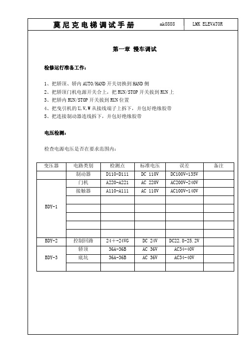
功能说明 电子热保护 瞬间停电动作 上限频率 下限频率 启动频率 启动频率保持时间 停止频率 载波频率
莫尼克电梯调试手册
参数号 F27 F36 F40 F42 E01 E02 E03 E04 E05 E06 E07 E08 E09 E10 E11 E12 E13 E14 E15 C01 C02 C03 C04 C05 C06 C07 C08 C09 C10 C11 C12 P01 P02 L56 0 0 0 00 2 2 8 30 40 50 8 4 13 0 多段频率 1 多段频率 2 多段频率 3 多段频率 4 多段频率 5 多段频率 6 多段频率 7 多段频率 8 电机极数 功率(KW) 转矩指令滤波系数 5 3.5 6 3.5 1 1 8 25 设定值 0 1 200 ### 0 1 2 10 X1 端子 X2 端子 X3 端子 X4 端子 X5 端子 X6 端子 X7 端子 X8 端子 X9 端子 加减速时间 3 加减速时间 4 加减速时间 5 加减速时间 6 加减速时间 7 加减速时间 8 跳越频率 1 跳越频率 2 跳越频率 3 功能说明
参数号 F02 F03 F04 F05 F06 F07 F08 F10
设定值 1 50 50 380 3 1.5 1
功能说明 操作方式 最高频率 电机额定频率 电机额定电压 加减速时间 1 加减速时间 2 电子热保护 1
参数号 设定值 F13 F14 F15 F16 F23 F24 F25 F26 0 0 50 0 0.0 0.0 0.1 15
莫尼克电梯调试手册
3
mk8888
LMK ELEVATOR
第一章 慢车调试
检修运行准备工作: 1、把轿顶、轿内 AUTO/HAND 开关切换到 HAND 侧 2、把轿顶门机电源开关合上,把 RUN/STOP 开关拔到 RUN 上 3、把轿内 RUN/STOP 开关拔到 RUN 位置 4、把曳引机的 U,V,W 从接线端子上拆下,并包好绝缘胶带 5、把连接制动器连线拆下,并包好绝缘胶带 电压检测: 检查电源电压是否在要求范围内: 变压器 电路类别 制动器 门机 接触器 BDY-1 检测点 D110-D111 A220-A221 A110-A111 标准电压 DC 110V AC 220V AC 110V 误差 DC100V-135V AC200V-240V AC100V-140V 备注
5610说明书完整版中联版
TC5610B版QTZ80(TC5610)塔式起重机使用说明书致用户感谢您选购和使用本公司的塔式起重机!为了使您正确使用与维护该设备,操作前敬请仔细阅读本使用说明书,并妥善保管,以备查询。
本使用说明书中标有“注意:”的语句,涉及到施工的安全,敬请注意。
本公司致力于产品的不断完善,产品的某些局部结构或个别参数更改时,恕不另行通知。
如有疑问,请与本公司联系。
出厂编号:出厂日期:本公司致力于塔机的不断完善,满足用户的各种需求,随机文件变化频繁。
该编号的随机文件与该编号的主机一一对应,切忌混用!即使是同型号塔机,也不保证适用!目录概述............................................................................ 0-1~0-8第一篇塔机的安装第一章立塔.......................................................... 1.1-1~1.1-32 第二章拆塔.......................................................... 1.2-1~1.2-3 第二篇塔机的使用与维护第一章塔机安全操作规程.................................... 2.1-1~2.1-3 第二章机构及电气操作........................................ 2.2-1~2.2-5 第三章安全保护装置.......................................... 2.3-1~2.3-4 第四章保养与维修............................................... 2.4-1~2.4-4 附录一.................................................................... 1~7编制:校对:审核:概述TC5610 塔式起重机,是长沙中联重工科技发展股份有限公司按J G/T5037-93《塔式起重机分类》设计的。
- 1、下载文档前请自行甄别文档内容的完整性,平台不提供额外的编辑、内容补充、找答案等附加服务。
- 2、"仅部分预览"的文档,不可在线预览部分如存在完整性等问题,可反馈申请退款(可完整预览的文档不适用该条件!)。
- 3、如文档侵犯您的权益,请联系客服反馈,我们会尽快为您处理(人工客服工作时间:9:00-18:30)。
Copyright © 2007 Nokia。版權所有。
1
目錄
目錄
安全 ..................................................6 一般資料 ...........................................7
有用的提示 ........................................................... 7 關於本裝置 ........................................................... 8 網絡服務 ............................................................... 9 增強配套 ............................................................... 9 密碼 ....................................................................... 9 下載內容 ............................................................. 10 諾基亞網上支援 ................................................. 10 航空操作模式 .....................................................15
輸入法 ............................................ 18
選擇書寫語言 .....................................................18 輸入法 .................................................................18 筆劃輸入法 .........................................................18 拼音輸入法 .........................................................19 輸入詞組 .............................................................19 分隔符號..........................................................20 用戶自定義詞組..............................................20 啟動與關閉智慧英文輸入法 .............................20 傳統英文輸入法 .................................................20 智慧英文輸入法 .................................................20 書寫文字的秘訣 .................................................21
本產品擁有 MPEG-4 視覺專利組合許可證,(i) 在消費者參與個人和非商業 活動下符合 MPEG-4 視覺準則提供的資料,這些資料只作個人和非商業性 使用,以及 (ii) 與 MPEG-4 影像連接一起使用,影像由持牌的影像供應商 提供。未授與、亦未包含其他方面的使用許可。包括推廣性、內部及商業 用途在內的附加資料可從 MPEG LA, LLC 獲得。請瀏覽 。 諾基亞奉行持續研發的政策。諾基亞保留對本文所描述之任何產品進行更 改及改進的權利,恕不預先通知。 在適用法律許可的最大範圍內,任何情況下對資料遺失、收益損失或因此 所引致的任何特別的、意外的、連帶的或間接的損失,諾基亞恕不負責。 本文件的內容以 「現有形式」提供。除所適用的法律外,諾基亞不對本 文件的正確性、可靠性或其內容提供任何保證,不論是明示或暗示的,包 括但不限於適銷性及針對特定目的的適用性的暗示保證。諾基亞保留隨時
通........... 16
撥打語音電話 .....................................................16 接聽或拒絕語音通話 .........................................16 單鍵撥號 .............................................................16 增強的語音撥號 .................................................16 通話期間的選項 .................................................17 來電等待..........................................................17 撥打視像通話 .....................................................17
0434
修訂或收回本文件的權利,恕不預先通知。如需最新產品的資料,請參閱 。 特定產品、產品應用程式及服務的供應情況可能根據地區的不同而有所分 別。請向您的諾基亞經銷商查詢以獲取詳細資料及提供的語言選項。 出口控制 本裝置可能含有受美國及其他國家出口法律及法規約束的物品、技術或軟 件。禁止與法律相抵觸的改動。 本裝置中提供的第三方應用程式由不從屬於或關聯於諾基亞的個人或團體 建立和擁有。對於這些第三方的應用程式,諾基亞並不擁有版權或知識產 權。因此,諾基亞並沒有責任向終端用戶提供支援或保證這些應用程式的 功能,亦不會對這些應用程式或物件上的資料負責。諾基亞對這些第三方 應用程式不負任何擔保責任。 如您使用這些應用程式,表示您清楚知道應用程式以 「現有形式」提供, 不論明示或暗示及在法律覆蓋範圍下均沒有保證。您亦清楚無論諾基亞及 其附屬機構均沒有發表任何陳述或保證,不論明示或暗示,包括但不限於 標題的保證、能切合特定目的或達致特定目的的經營能力,或應用程式不 會侵犯第三者的專利、版權、商標或其他權利。
快速入門 .........................................11
安裝 SIM 卡和電池............................................ 11 為電池充電 ......................................................... 11 開機及關機 ......................................................... 12 設定時間、時區和日期 ..................................... 12 配置設定服務 ..................................................... 12 天線 ..................................................................... 12 腕帶 ..................................................................... 13 按鍵及插孔 ......................................................... 13 microSD 記憶卡 ................................................. 14 待機模式 ............................................................. 14 指示符號 ......................................................... 14
2
Copyright © 2007 Nokia。版權所有。
編寫及發送文字訊息 .........................................22 編寫及發送多媒體訊息 .....................................22 閱讀及回覆訊息 .................................................22 Nokia Xpress 聲音短訊 ......................................22 快顯訊息 .............................................................23 電子郵件應用程式 .............................................23 電子郵件設定精靈..........................................23 編寫及發送電子郵件......................................23 下載電子郵件..................................................24 閱讀及回覆電子郵件......................................24 聊天室 .................................................................24 留言訊息 .............................................................24 訊息設定 .............................................................24 標準設定..........................................................24 文字訊息..........................................................25 多媒體訊息......................................................25 電子郵件訊息..................................................26
