一种基于单片机的新型三相多费率电能表的设计
基于单片机PIC16F877A和计量芯片ATT7022A的三相多功能复费率电能表的设计

基于单片机PIC16F877A和计量芯片ATT7022A的三相多
功能复费率电能表的设计
陈金辉;韩媛媛;武文平
【期刊名称】《电力系统保护与控制》
【年(卷),期】2010(038)002
【摘要】三相复费率电能表以microchip公司PIC16F877A单片机作为核心控制芯片,以珠海炬力的ATT7022A作为计量芯片,实现了复费率计量、电能管理、事件记录、自动抄表等功能,从芯片的主要功能、主要硬件电路的组成、主要模块的作用以及电能表的软件系统等三方面给出了详细论述.
【总页数】3页(P98-100)
【作者】陈金辉;韩媛媛;武文平
【作者单位】华北保定电力职业技术学院电气工程系,河北,保定,071051;河北电力自动化研究所,河北,保定,071051;华北保定电力职业技术学院电气工程系,河北,保定,071051
【正文语种】中文
【中图分类】TM73
【相关文献】
1.计量芯片BL6522在三相多功能电能表中的应用 [J], 詹迪霞;
2.计量芯片ADE7758在三相多功能网络电能表中的应用 [J], 陈志忠;徐月华
3.基于ATT7022A的三相IC卡预付费电能表设计 [J], 罗涛;李啸骢;廖丽莹;孔令怡;
胡文霞
4.基于MSP430单片机的多功能复费率三相电能表 [J], 赵宇
5.基于ATT7022A的三相三线多功能电能表 [J], 龙健; 徐岩
因版权原因,仅展示原文概要,查看原文内容请购买。
基于单片机的一个新的三相多费率电度表的设计

基于单片机的一个新的三相多费率电度表的设计吉顺江电气与电子工程学院山东理工大学淄博,255091,中国jandj8@摘要:随着社会的发展,对电力的需求变得越来越大。
在不同的时间不平衡电的现象是每况愈下。
以调整原因,电力负荷,节约能源,我们提出了一种新的多速率三相电度表的设计。
本文提出了一种新型的三相多费率meterbased A T89L V5的瓦小时的设计原则。
详细介绍了硬件和软件流程,以及对实验数据的分析设计。
由淄博贝林电子有限公司试生产,它表明,这种多速率三相电度表的特点是行走精度,精确的测量,自动抄表,灵活的时间设置和低成本。
因此,这种新型多费率电度表,具有广阔的应用前景。
关键词:多速率,三相电度表A T89LV52导言计算机技术的发展和应用,推动建筑智能化节表里。
因为在不同的时间更大的电力需求和不平衡的电力的现象愈演愈烈,电力公司鼓励人们使用多费率电度表[1],以调整合理的电力负荷和节约能源。
一直采用传统的多费率电度表机械马口铁来衡量。
也有一些缺点,测量精度与机器磨损,单一时间设置和强大的人力资源[2]内。
在本文中,我们提出了一种新的多速率A T89LV52基于三相电度表。
这三相多费率电度表采用AD7752测量。
它的特点是分时测量,精确的测量,液晶显示,自动抄表,灵活的时间设置,及时校正,成本低,设计新颖二。
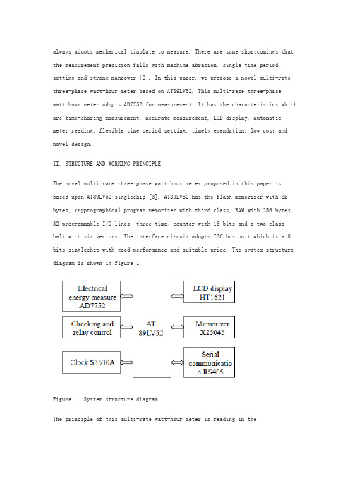
结构与工作原理新颖的三相多费率电度表本文提出根据AT89LV52单片机[3]。
AT89LV52有快闪存储器8K字节,第三类cryptographical程序存储器,256字节,32个可编程I / O线,三个时间/计数器与16位和停止两个类有六个向量RAM。
接口电路采用I2C总线的单位,这是一个8位单片机具有良好的性能和合适的价格。
系统结构框图如图1所示。
阅读本多费率电度表的原则是在多速率的时间段使用RS485总线,并注意到在X25045的然后接管惩时钟的RS485总线和写时钟的CMOS芯片S3530A。
基于单片机的三相电源相序控制设计

基于单片机的三相电源相序控制设计三相电源相序控制设计是一种基于单片机的电源控制技术,用于控制三相电压源的相序。
相序是指三相电压波形的相位差,确定了电流的流向和方向,对于三相设备的运行稳定性和正常工作非常重要。
在一些应用中,如电机驱动、制冷系统和能量转换装置等,需要确保相序正确,以保证设备的正常运行。
本文将介绍基于单片机的三相电源相序控制设计的原理、系统框架和具体实现。
一、原理相序控制设计的原理基于对三相电压波形进行采样和处理,根据不同波形特征判断相序是否正确,并通过单片机控制实现自动相序修正。
具体原理如下:1.采样:使用三个模拟输入通道分别采样三相电压波形,将采样值转换为数字信号。
2.处理:对数字信号进行波形处理,获取波形的相位差、幅值和频率等特征参数。
3.判断:基于特征参数,判断三相电压波形的相位差是否满足相序要求。
4.控制:根据判断结果,通过单片机控制,实现相序修正。
二、系统框架1.采样模块:由三个模拟输入通道和ADC转换器组成,负责对三相电压波形进行采样。
2.处理模块:由单片机控制,对采样得到的数字信号进行波形处理,提取特征参数。
3.判断模块:根据特征参数,判断三相电压波形的相位差是否满足相序要求,并输出判断结果。
4.控制模块:根据判断结果,控制继电器或电子开关等元件,实现相序修正。
三、具体实现1.选择合适的单片机控制器,具有足够的输入输出通道和计算处理能力。
2.连接三相电压源和单片机控制器,采用适当的线缆和接口电路。
3.编写单片机控制程序,实现采样、处理、判断和控制功能。
4.设计电源相序判断算法,根据不同的特征参数进行相序判断。
5.在单片机程序中加入相序修正的控制逻辑,实现自动修正相序。
6.调试系统,通过实验验证方案的正确性和可行性。
最后,可以根据实际需求,对相序控制系统进行优化和改进。
例如,可以加入故障检测和报警功能,提高系统的可靠性和安全性。
同时,还可以考虑通过通信接口与其他设备进行联动控制,实现更多的功能和应用。
基于ADE7758的复费率三相电能表设计
基于ADE7758的复费率三相电能表设计牛广文【摘要】设计了基于电能计量芯片ADE7758和单片机PIC16F877为核心的复费率三相电能表,实现了复费率电能计量、记录、自动抄表等功能.对具体的电压电流采样电路、计量电路、时钟电路、RS-485和红外通信电路等进行设计,并给出了系统软件流程图.设计的电能表硬件电路简单,抗干扰能力强,不同的通信接口方便用户使用,具有一定的应用价值.%A three-phase multi-rate electric power meter based on energy measurement chip ADE7758 and PIC16F877 single chip was developed. The meter realizes multi-rate electric power measurement, register and automatic metering. The measuring circuit of voltage and current,calendar and clock circuit, RS - 485 interface and infrared communication circuit was designed. And system software flow diagram was given. Hardware design of the meter circuit is simple,anti-interference ability,different communication interface user-friendly,has a certain value.【期刊名称】《工业仪表与自动化装置》【年(卷),期】2012(000)003【总页数】3页(P105-107)【关键词】复费率;三相电能表;PIC16F877单片机;ADE7758【作者】牛广文【作者单位】兰州工业学院电气工程系,兰州730050【正文语种】中文【中图分类】TP368.10 引言我国许多电网在负荷高峰时,经常拉闸限电,而在负荷低谷时则浪费严重,导致水电厂大量弃水,火电厂长时间低负荷运行,使发、供电设备的容量不能充分利用,运行不经济。
一种基于单片机的新型三相多费率电能表的设计外文文献及翻译
always adopts mechanical tinplate to measure. There are some shortcomings that the measurement precision falls with machine abrasion, single time period setting and strong manpower [2]. In this paper, we propose a novel multi-rate three-phase watt-hour meter based on AT89LV52. This multi-rate three-phasewatt-hour meter adopts AD7752 for measurement. It has the characteristics which are time-sharing measurement, accurate measurement, LCD display, automatic meter reading, flexible time period setting, timely emendation, low cost and novel design.II. STRUCTURE AND WORKING PRINCIPLEThe novel multi-rate three-phase watt-hour meter proposed in this paper is based upon AT89LV52 singlechip [3]. AT89LV52 has the flash memorizer with 8k bytes, cryptographical program memorizer with third class, RAM with 256 bytes, 32 programmable I/O lines, three time/ counter with 16 bits and a two classhalt with six vectors. The interface circuit adopts I2C bus unit which is a 8 bits singlechip with good performance and suitable price. The system structure diagram is shown in figure 1.Figure 1. System structure diagramThe principle of this multi-rate watt-hour meter is reading in themulti-rate time segments using RS485 bus and noting in X25045 then take over correctional clock with RS485 bus and write in clock CMOS chip S3530A. The three-phase AC voltage and electric current pass through potentiometer and mutual inductance instrument respectively so as to produce small signal which is sent to AD7752 to complete measurement. The clock CMOS chip S3530A gives clock information per second in the course of automatic move and analyze this clock belongs to which period of time according to advance periods of time set in X25045 then save the electrical energy in RAM memorizeraccording to corresponding period of time. We write it to corresponding address of X25045 when the electrical energy achieves one degree in order to make the multi-rate measurement come true. This watt-hour meter hasfunctions of clear LCD display, missing phase detection, burthen control, halt electricity check and storage, automatic meter reading and so on.III. THE DESIGH OF HARDWARE CIRCUITA. Electrical energy measurementThe three-phase electrical energy measurement is realized by the low consume CMOS chip AD7752 of ADI company. The inside of AD7752 adopts digital circuit besides ADC, filter and multiplication circuit which can eliminate noises effectively. The sampling course of voltage and electric current in three-phase AC power supply loop is shown in figure 2 in which IA stands for voltage sampling of A phase. The sampling circuits of B phase and C phase are similar to A phase. The power after integral is transformed to electrical pulse for output. The pulse of fan-out CF enters intointerregnum INT0 of AT89LV52 through photoelectricity insulation 4N25. CPU measures the electrical energy [4]. We adjust the pulse number of CF by combining the state of S1 and S2. The connection of electrical energy and pulse is W = M C . In which, W is the electrical energy with the unit of kilowatt-hour, M is the total pulse number, C is the pulse number of ammeter. We choose C equals to 3000 that is to say every kilowatt-hour is 3000pulses.Figure 2. Circuit schematic diagramof watt-hour meterB. LCD displayThe LCD display [6] adopts HT1621 CMOS chip of HOLTEK Company toachieve twelve bits digital display. HT1621 is the LCD drivers with 128 segments (32× 4) inner memorizer. The interior of HT1621 consists ofcontrol and time circuits, RAM, LCD drive and watch timer. It hasthe merits of small volume and low cost so that it is suit to watt-hour meter. We use serial interface which only has four lines between HT1621 and AT89LV52. The detailed connection is shown in figure 3. P20, P21, P22 and P23 of AT89LV52 connect to CS, RD, WR and DATA respectively with the use to refurbish the display of RAM. HT1621 drive CMOS chip has 48 nodes in which COM0, COM1, COM2,COM3 connect to the communal end and drive output of LCD and SG0, SG1, SG2, SG3 connect to drive output of every segment respectively. In addition, an adjustable resistance of 20kΩ is put between VDD and VLCD to adjust the display contrast of LCD. Experiment shows that the contrast is better withVDD=5V and VLCD=4V.C. Serial memorizerSerial memorizer adopts low power consumption chip X25045 of XICORcompany .It has three functions which are watchdog timer WTD, voltage supervision and serial memorizer E2PROM with 512 bytes. WTD can be set 200ms, 600ms and 1400ms time intervals. The software program is read into X25045. During the normal running of program, WTD receives the trigger signal in time intervals in order to ensure the normal running of program. X25045 will output a high potential through RESET line if WTD does not receive trigger signal in time intervals. The trigger watt-hour meter reset in order to prevent program flying away. As the serial memorizer chip, 512 bytes of X25045 are used to storage the watt-hour meter code, multi-rate periods of time, the apex electricity, smooth electricity, vale electricity and total electricity of last month and this month. Storage can be divided into two same areas. One is used as data storage. The other is used for backup. The number of storage can be revised 100,000 times. Data can be stored for 100 years. It is connected with AT89LV52 by SPI agreement bus. The connection is shown in figure 3.D. Clock circuitThe clock circuit is completed by S3530A chip. It is a low powerconsumption clock chip that supports I2C Bus. It sets the clock and calendar according to the data received by CUP communicating with RS485. At the same time, it continues to walk time by its own oscillation. The crystaloscillator of 32.768 kHz is put between Xin and Xout of S3530A which is connected with CPU through latching. SDA foot and SCL foot connect to P1.6 and P1.7 of AT89LV52 respectively. There are two interrupt alarming foots can be set as second output or minute output synchronizing pulse which supply interrupt signal to AT89LV52 with one second period. Single-chip system will readout the current time through I2C communication interface according to this signal and calculate the period of time that this moment belongs to so as to realize the electrical energy measurement in different periods of time [5]. This clock circuit has spare lithium battery. The powersupply VCC supply power in normal wiring and electrified for lithium battery of 3.6V. When there is power off, the system will automatically convert lithium battery to clock circuit for power supply. The clock will still running accurately even the power is off.Figure 3. Partial circuit figure of watt-hour meterE. RS485 CommunicationMAX485 chip can implement RS485 communication control ofmulti-rate watt-hour meter. MAX485 chip has RS485 communication protocol. It can take 128 hypogenous computers. Its transmission distance is greater than1km and its transfer rate is up to 250kb per second. The watt-hour meter connects with the unit controller through the RS485 bus. Each unit has a cell controller can manage 128 multi-rate watt-hour meter. The cell controller connects to power management computer. Each watt-hour meter has one and only meter number with eight bits of hex. The electrician should write the user’s information and meter number and then import to the power management computer for initial installation so ad to complete the connection of user and management computer. Management computer sends setting of period of time and clock information with the manner of broadcast communication without address information. PC uploads information by the way of calling address.F. Lack Phase detection and relay controlIt can achieve relay control [7] with P27 of AT89LV52. P27 cancontrol relays using 4N25 photoelectricity isolator so as to complete powersupply and power control. Lack Phase detection gets the signal from fan-out of the relay and connects to 1 foot of photoelectricity isolator after passing a 75K resistance, the diode half-wave rectifier and capacitivefiltering respectively. We detect the 4 foot of isolator to determine whether there is the lack of phase. If there is lack of phase, we detect again after 2 seconds overtime. We break off the power immediately if there is lack of power after the twice confirmation. In power protection circuit, it uses the INT1 interrupt foot of AT89LV52 to detect signal.When there is a sudden power off, INT1 jumps into a low voltage and the INT1 interrupt enters to the power protection program relying on the energy storage capacitor to save data. In the system, pulse output of AD7752, relay control port and the inputs of lack phase detection all use photoelectric isolator4N25. It sends electrical signal by light coupling which can enhance theability of anti-jamming.IV. THE DESIGN OF SOFTWAREA.The distribution of resourceThe software program includes main program, X25045 read and write program,RS485 serial communication program, interrupt serve program, timer handling program, HT1621 display control program, electrical energy measurement in different period of time and power down protection program, and system self-checking and anti-interference handling program. Interrupt resourcedistribution of system is: INT0 interrupt is used as AD7752 pulse measurement, INT1 as synchronization detecting, timer T0 as 100 ms timing, T1 as 1ms timing, and T2 as baud rate generator for serial communication program. RS485 asynchronous communication is set to receiveinterrupt and check information for sending.B. Module desighThe flow chart of main program is shown in figure 4. The watt-hourmeter should be able to initialize at each power up time. The initializing program includes setting working mode of timers, serial stomata and interrupts for AT89LV52, writing control word into X25045, S3530A and HT1621. This system sets three periods of time. The singlechip reads clock value from S3530A per second then analyze this clock belongs to which period of time according to advance periods of time set in X25045 then save the electrical energy in RAM memorizer according to corresponding period of time. We write it to corresponding address of X25045 when the electrical energy achieves one degree. The LCD display with 16 bits shows period of time and electrical energy information in turn. Figure 4. Flow chart of main programV. TESTING RESULTError measurement and running test have been made in Zibo Billion Electron Co., Ltd. The epigenous computer completes the setting of time management. There arethree-rate period of time. The first period of time is vale electricity from 00 point 00 minute to 06 point 30 minutes. The second period of time is apex electricity from 06 point 30 minutes to 22 point 30 minutes. The third period of time is smooth electricity from 22 point 30 minutes to 24 point 00 minute. The setting of rate period of time is sent to computer management system by electric power company according to national policy and saved in X25045. The apex electricity, smooth electricity, vale electricity and total electricity per month read saved in electrical energy meter and sent to epigenous computer through cell controller. The communication baud rate is 9600 bits per second. The checkout platform of 0.1 grade standard electronic power meter is used as standard meter and the multi-rate watt-hour meter is the tested meter. Billion Electron Company has carried out testing according to different load running. The measured data is shown in table 1 with the burthen of 30kW.TABLE I. COMPARE OF NORMAL METER AND TESTING METERThe testing result indicates that the error of this multi-ratewatt-hour meter is less than 1%, belongs to 1.0 grade. The return reading of electrical energy is precision and the emendation of time is timely and right. By testing, the method of decreasing errors for electricity metering can be obtained. Firstly, adjust the sampling resistance of AD7752 to accurate value. Secondly, the value of this resistance is needed less varying with temperature. Thirdly, during electricity metering progress, when mantissa portion of electricity is less than 0.01, the remaining pulse should be accessed together, thus cumulative error caused by lack of 0.01degree energy loss could be avoided.VI. CONCLUSION AND EXPECTATIONThe multi-rate watt-hour meter achieves electrical energycomputation in different time according to different time setting. It adopts RS485 for serial communication and realizes automatic meter reading and real-time emendation. The results of production in Billion Electron Company showthat the multi-rate three-phase watt-hour meter proposed in this paper has the characteristics of novel design technique, accurate measurement, and flexible time period setting. Various technical indexes achieve the technique standard for national intelligent card watt-hour meter. Therefore, it has wide application.REFERENCES[1] Bu Zhengliang, Yin Xianggen, Tu Guangyu. “Development of HV Watt-hour meter.” Automation of Electric Power Systems, 2006, 30(19): 89-93.[2] Kosukegawa M., Sakumoto Y. “Traceability system of electric energy standard and tendency in static watthour meter development in Japan.” Sixth International Conference on Metering Apparatus and Tariffs for Electricity Supply, 1990,4: 259-263.[3] Xuehai Li. Applied tutorial of singlechip. Electronic industry publishing company, 2003.[4] Al-Khateeb Tarik, Blundel Martin. “An electronic meter for measuring the saving in electrical power.” The Ninth Arab International Conference on Solar Energy (AICSE-9), Kingdom of Bahrain, 2007,4 (209):328-333.[5] Liu Ying, Liu Qingyu. “Development of a self-calibration precision electrical measuring meter.” Proceedings of the 1998 Conference Precision Electromagnetic Measurements, 1998,7:276.[6] Gao Yun-Peng, Teng Zhao-Sheng, Liu Peng. “Design of three-phase multi-functional harmonic energy meter.” Journal of Hunan University Natural Sciences, 2008, 35(9): 53-57.[7] Qu Qingchang. “Key technology to three-phase electric meter and high voltage electric power measurement.” Acta Metrologica Sinica, 2007, vol28: 25-30.一种基于单片机的新型三相多费率电能表的设计Jishun Jiang Lanlan YuSchool of Electric and Electronic Engineering School of Electric and Electronic Engineering Shandong University of Technology Shandong University of Technology Zibo, 255091, China Zibo, 255091, China摘要:随着社会的发展,对电力的需求变得越来越大。
毕业设计(论文)基于单片机的数字电能表设计

毕业设计(论文)题目名称:基于单片机的数字电能表设计就读学校:河南工学院专业:工业自动化学生姓名:指导教师:中原工学院继续教育学院2016年4月基于单片机的数字电能表设计The design of digital watt-hour meter based on single chip microcomputer就读学校:河南工学院专业:工业自动化学生姓名:指导教师:2016年4月摘要19世纪三四十年代,中国人民的照明途径还是主要由煤油灯为主,而在经济飞速发展的,科技产品日新月异的今天,电的应用已经深入中国人民的日常生活。
电灯、冰箱、空调等等,统统都与电有着密切的关系。
电在当今社会不可或缺,同样也涌现出了对电量的计量,从而出现了电能表这一计量仪表。
电能表的发展历程主要是由最初的单一费率电能表到如今的复费率电能表。
这与我国的多费率用电政策有关,旨在消峰镇谷,平衡用电。
同样,在现在科技飞速发展,各种电器,仪表都逐渐趋近于自动化、人性化和智能化。
而这些电气设备大都含单片机或者是CPU控制器。
在本次设计中将智能化技术融入电能表中,电能表作为重要的计量仪表,准确性、稳定性都是很重要的。
而数字电能表具有精度高、测量准确、读数直观、使用方便等优点。
本设计以AT89C51单片机为核心,以逐次比较型A/D转换器ADC0809、八段数码管为主体,构造了一款简易的数字电能表,能够实现同时测量8路0.00~5.00V的直流电压,最小分辨率为0.02V。
关键词:AT89C51;ADC0809;数字电能表;八段数码管ABSTRACTThirties and 19th century, the Chinese people's way of illumination is mainly composed of kerosene lamp is given priority to, and with the rapid economic development, science and technology products with each passing day today, the applications of electricity have the Chinese People's Daily life. Lights, refrigerator, air conditioner and so on, all has close relationship with electricity. Electricity is essential in today's society, and also emerged for the measurement of the power, thus appeared the watt-hour meter measuring instrument. The developing course of watt-hour meter is mainly composed of a single rate, initial watt-hour meter in today's complex rate watt-hour meter. This is associated with rate more electricity policy of our country, aimed at peak valley town, balance of power. Also, in what is now the rapid development of science and technology, all kinds of electrical appliances, instrument has gradually tend to be automated, humanization and intelligent. But most of these electrical equipment including microcontroller or CPU controller.We will integrate the intelligent watt-hour meter in the design of watt-hour meter as important measuring instrument, the accuracy, stability is very important. And digital watt-hour meter with high precision, measurement accuracy, reading the advantages of intuitive and easy to use. This design USES AT89C51 single-chip microcomputer as the core, to compare successive type A/D converter ADC0809, eight digital tube as the main body, constructed A simple digital watt-hour meter, can be achieved at the same time measuring 8 road from 0.00 V to 5.00 V dc voltage, minimum resolution of 0.02 V.Keywords: AT89C51;ADC0809;Digital watt-hour meter;Eight digital tube目录第1章绪论 (1)第2章总体方案选择 (2)2.1方案一:由数字电路及芯片构建。
基于MSP430F149单片机的智能远传三相电表设计

基于MSP430F149单片机的智能远传三相电表设计陈晓龙;裘友凤【摘要】电能表是电力企业收取电费的直接工具,其性能稳定性、测量准确性和可靠性关系到电力部门和用户之间的结算问题.现有的电能表集抄模式还存在着谐波干扰、人工和无线网络的传输质量与速率等问题.本文主要介绍一种基于MSP430F149单片机为核心控制处理器的智能远传三相电能表的软、硬件设计.该仪表集电量参数监测计量与显示为一体,电量参数监测采用专用测量芯片CS5460A,液晶显示.该电表具有集成度高、功能强、成本低、抗干扰能力强、功耗低等优点,能够满足电能智能化管理的要求.它还能通过ENC28J60芯片与主控制器通信连接实现数据远传功能,可以方便地实现实时监测、数据采集、查表打印、系统监控等功能,是电能表集抄未来发展的一大趋势,具有很好的应用前景.【期刊名称】《制造业自动化》【年(卷),期】2011(033)002【总页数】3页(P166-168)【关键词】智能电表;MSP430F149;CS5460A;ENC28J60【作者】陈晓龙;裘友凤【作者单位】江西旅游商贸职业学院,南昌,330100;江西交通职业技术学院,南昌,330013【正文语种】中文【中图分类】TP3111 智能远传三相电表硬件总体设计思路智能远传三相电表作为一种以网络为通道的远程自动抄表系统,具有实时性好、测量准确、成本低、便于管理等优点,将逐步成为电能表发展主流。
该智能远传三相电表以MSP430F149单片机为核心控制处理器,采用专用计量集成电路芯片CS5460A作为三相电能采样与数据处理,完成传统的三相电表功能;并通过ENC28J60芯片与主控制器连接实现数据远传功能。
系统硬件组成及结构框图如图1所示。
图1 硬件组成及结构系统框图该项目的硬件电路设计主要包括四个部分内容:1)单片机控制系统;2)三相电能采样与数据处理电路;3)ENC28J60芯片与主控制器通信电路;4)实现各功能要求所必需配置的外部设备,如按键、显示器等。
基于单片机的三相电能表的设计
摘要本文以智能计量总表为研究对象,采用计量芯片ADE7758和AT89$52设计三相电能表,介绍了计量电路原理、系统结构特点以及分段计量的软件设计与实现。
针对10—35kV输配电网正常负荷和超低负荷两种情况下的精确计量,提出按功率额度实时分段计量的电能表设计方案;为了调整电力负荷曲线,针对用电量的时间不均衡问题,提出复费率分时段计量方案。
采用双变比电流传感器进行信号的检测采样,当负荷电流低于额定电流的20%时,单片机通过检测功率,自动切换到低负荷计量回路,即小电流比计量回路,最大限度降低了电流传感器低负荷运行时造成的信号检测误差,提高电能计量精度。
单片机通过对瞬时有功功率的检测,实现了计量回路的实时选通切换和功率分段计量:通过对时间参数的检测,实现了定时存储和分时段计量。
根据电能表参数配置进行ADE7758初始化参数计算。
为了评估电能表计量数据的真实性和有效性,对模拟信号输入电路进行试验设计,应用ME300B单片机开发系统进行在线仿真调试。
以功率参数为性能指标,通过仿真试验,对功率参数的理论值和电能表的显示值两组数据进行分析比较,得出电能表计量数据是真实有效的结论。
采用双变比电流传感器进行电能表设计,扩大了负荷计量范围,提高了电能计量精度,且计量回路切换无需进行人工干预。
该方案有望实现全量程的精度均衡和精确计量,为具有实时分段计量功能的三相电能表设计提供一种可行的方案。
目前,已完成样表的设计与测试工作。
基于精确的试验平台,完成对电能表的增益和偏差校准,即可进行现场试验和数据采集,具有良好的市场应用前景。
关键词:三相电能表,实时分段,精确计量,仿真试验,ME300B,ADE7758,AT89S52符号约定及其说明一、变量定义及显示代码(斜体时表示变量,正体时表示显示代码)RO 总的无功电量ED 总的有功电量EJ 分时段有功电量(00:00~12:00)E2 分时段有功电量(12:00~00:00)E3 按负荷功率分段小负荷计量时有功电量E4 按负荷功率分段正常负荷计量有功电量P 瞬时有功功率V 瞬时无功功率H1 断相事件次数H2 单相过流事件次数H3 单相过压事件次数二、按键功能说明K1 手工复位K2 分时段电量参数查询显示K3 按功率分段电量参数查询显示K4 瞬时有功、无功功率参数查询显示三、电能表参数MC 电能表脉冲常数PO 有功功率分段参考Imax 满足计量精度的负荷额定最大电流Vn 负荷额定电压值Vf ADE7758电流、电压通道信号输入Ifullscal ADE775 8电流通道满刻度输入对应的负荷电流Vfullscale ADE7758电压通道满刻度输入对应的负荷电压Wh/LSB ADE7758有功能量寄存器最低有效值VARh/LSB ADE7758无功能量寄存器最低有效值第一章绪论电能表技术正向着复费率、多功能、网络化的方向发展。
基于STM32的三相多功能电能表解决方案
1 n 2 uk n k 1
u k —电压采样值
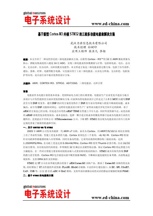
式中:U-电压有效值,n-每周期采样点数,
电流测量(有效值)计算式: I
1 n 2 ik n k 1
式中:I-电流有效值,n-每周期采样点数, ik -电流采样值 在得到的电流电压有效值基础上计算出总功率 S(即视在功率),通过对时间积分的电流电压积得到有 功功率 P,无功功率 Q 是总功率 S 与有功功率 P 之差,功率因数是有功功率 P 与总功率 S 的比。 对于单器件和三相四线星形负载的有功功率和无功功率的计算汇总如下: 单元件有功功率计算式: P
图4
AD73360 与 STM32 的接口电路
与滤波网络 由 STM32 的 GPIO 控制 AD73360 的 SE 和 RESET,并用一个外部中断输入脚来监听帧同步信号,这样 才可以用程序来保证数据帧内容的字节对应关系。 在 STM32 的硬件设置程序中,需要关闭 SPI 的所有中断,设置 SPI 为从模式,并选取一个 DMA 通道 与之协同工作,自动将 SPI 从模式收到的数据保存在指定的内存地址。为了令 AD73360 正确采集数据,还 必须根据使用要求配置 AD73360 的内部寄存器, 令 AD73360 处于数据模式并主动向 STM32 发送采样数据。 三、主要电能参量的计算
AD73360 是固定周期采集,我们使用的是 150Hz 或 160Hz,即每周期采集 150/160 点,为此 AD73360 采用的时钟是 6.000MHz 或 16.384MHz, 系统中对 AD73360 的配置为 DMCLK 分频因子为 2048。 AD73360 是差分采集,很方便进行过零点检测和直流分量调节,以保证信号幅度对称,从而减小系统误差。 电压测量(有效值)计算式: U
基于ATMEGA32单片机的三相网络电力仪表的研制

.
智 能 仪 器仪 表
基于 A ME A 2单片机 的三相 网络 电力仪 表 的研 制 T 3 G
叶 国 文
( 丽水学院 电子信 息工程 系,浙 江 丽水 330) 200
[ 摘要] 介绍 了以低功耗单片机 A ME A 2设计的三相 网络 电力仪表的设计原理、 T G 3 硬件组成 、 软件设计、 测量功能。
21信号的采样 .
211电压 的采 样 ..
作 者 简介 : 国文 (9 6 ) 男, 叶 1 6 一 , 高级 工程 师, 事 电子信息、 从
自动化技术 的教 学、 究及应用工作 。 研
本 设计 采 用 电压互 感 器 1/ 电网 电压 ( 2 0 ) 、将 如 2 V 变
电工技术 l 0 7l 0 2 8期 l 3
进一步发展的趋势。随着电能计量芯片发展和完善 ,使
得 采 用 电能 计量 芯 片 和 MCU设 计 的 多 功能 电子 式 电能
表不仅能实现电能表 的各种功能,而且具有精度高,功
能 扩展 方 便,软 件 易 实 现 等优 点 。本 课 题 正 是 基于 A — T ME A 2单 片 机和 r7 2 G 3 _ 0 2计量 芯 片 相 结 合 而 研 制 的 r
运输温度:一 O + O 4 ~ 8 ℃;存贮和工作湿度:≤8 %; 5
() 9 外形 尺 寸:9 m 9 mmx 4 m; 6 mx 6 8m
(O 重量 :约 O4 g 1) .k 。
2 硬 件 系统 设计
硬 件系 统结 构示 意 图如 图 1 。
收 稿 日期 : 0 7 0 — 2 2 0 —40
测 量 参 数精 度 技 术 指标 如表 1 。测 量参 数 电流 、电 压 误 差 要 求 为 O2 。分 析 计 量 芯 片 A T 0 2 可 知 : . % T 72B
基于单片机的三相电能表的设计
摘要随着我国经济的飞速发展,电能消耗日益增加,电能成为现代社会国民经济和人民生活的重要保障。
本文所设计的新型多功能电子式电能表除了提高计量精确度外,还实现了分时计量、对异常情况进行实时监控并记录事件等功能;可提高电能的综合利用,为用户提供公正、公平的用电环境。
论文首先概述了电子式电能表的发展现状及电能测量基本原理,然后给出了系统的设计目标和总体方案,并对各个硬件电路单元进行了设计,包括电源单元、计量单元、功能管理单元、显示单元、通信接口单元等。
在软件设计方面,采用模块化软件设计理念实现了有功和无功的能量分时计量、红外通讯、RS485通讯、异常检测、按键显示及记录等功能。
最后介绍了三相电能表的抗干扰设计。
关键词:电能计量,多功能电子式电能表,复费率,A TT7022B,时钟芯片AbstractWith the rapid development of economy of our country and gradual increment of power onsumption, electrical energy becomes the significant guarantee of national economy and people’s life in modern society. Late-model polarity formula multifunction watt-hour meter, which designed in this paper, improves the measuring accuracy and realizes functions of time-sharing measurement real-time monitor exceptional situation and take event records and so on. This will improve the completely utilization of electrical energy, prevents happening of using electricity illegally, and provides fair and impartial environment of using electricity.At first, this paper summarizes the present developing state ofmulti-function electronic watt-hour meter and the basic theory of energy measurement, after that, it put out the design objection and whole frame of this metering System. And the circuit design of each unit with the function divided, including power unit, measure unit, communication unit etc .The soft design of the system is the priority of this paper, utilize modularization method to realize active power, reactive power, RS485 communication, infrared communication, keyboard and display, anomaly detection, electricity reading meter and so on. The EMC design and meter adjust method have also been discussed.Key Words: energy metering; Multi-function electronic watt-hour meter;A TT7022B; multi-rate; real-time clock目录第一章绪论 (5)1.1电能表的研究背景 (5)1.2电能表的发展及现状 (7)1.3课题研究目的和意义 (8)1.4本文的主要研究内容 (8)第二章电能表概述 (11)2.1电子式电能表的一般结构 (11)2.2电能表的分类 (12)2.3电能测量原理 (13)2.4电子式电能表的测量原理 (14)2.5本系统采用的测量方法 (16)第三章系统总体方案及硬件设计 (18)3.1硬件总体方案 (18)3.2主控芯片及其外围电路 (19)3.3电量信号采集和预处理 (23)3.4存储器单元 (29)3.5通信模块设计 (30)3.6实时时钟电路 (33)3.7人机接口模块设计 (35)3.8电源单元 (37)3.9继电器驱动单元 (40)第四章系统软件设计 (42)4.1 开发环境 (42)4.2主程序流程图 (42)4.3程序模块化设计 (43)第五章结论与展望 (50)5.1论文总结 (50)5.2本文的不足及课题展望 (50)参考文献 (52)致谢 (54)第一章绪论1.1电能表的研究背景在我国,计划调度、经济调度对于电力生产来说要求很高,电力生产的特点是发电、供电、用电同时完成,因此,电能作为一种不可储存商品,其流通在使用过程中,对其准确计量是非常特殊的,为调节负荷用电的时段,这样可以解决日渐突出的电力的供求问题,在不增添设新的备,不扩大容量的前提下,主要通过以下两种方法来解决:首先是通过行政的手段,在用电高峰时间段限、拉电,其次是通过经济的手段,实行分时段不同的电价,即不同时段实行不同电能的售价。
一种基于单片机的新型三相多费率电能表的设计外文文献及翻译
always adopts mechanical tinplate to measure. There are some shortcomings that the measurement precision falls with machine abrasion, single time period setting and strong manpower [2]. In this paper, we propose a novel multi-rate three-phase watt-hour meter based on AT89LV52. This multi-rate three-phase watt-hour meter adopts AD7752 for measurement. It has the characteristics which are time-sharing measurement, accurate measurement, LCD display, automatic meter reading, flexible time period setting, timely emendation, low cost and novel design.II. STRUCTURE AND WORKING PRINCIPLEThe novel multi-rate three-phase watt-hour meter proposed in this paper is based upon AT89LV52 singlechip [3]. AT89LV52 has the flash memorizer with 8k bytes, cryptographical program memorizer with third class, RAM with 256 bytes, 32 programmable I/O lines, three time/ counter with 16 bits and a two class halt with six vectors. The interface circuit adopts I2C bus unit which is a 8 bits singlechip with good performance and suitable price. The system structure diagram is shown in figure 1.Figure 1. System structure diagramThe principle of this multi-rate watt-hour meter is reading in themulti-rate time segments using RS485 bus and noting in X25045 then take over correctional clock with RS485 bus and write in clock CMOS chip S3530A. Thethree-phase AC voltage and electric current pass through potentiometer and mutual inductance instrument respectively so as to produce small signal which is sent to AD7752 to complete measurement. The clock CMOS chip S3530A gives clock information per second in the course of automatic move and analyze this clock belongs to which period of time according to advance periods of time set in X25045 then save the electrical energy in RAM memorizeraccording to corresponding period of time. We write it to corresponding address of X25045 when the electrical energy achieves one degree in order to make the multi-rate measurement come true. This watt-hour meter hasfunctions of clear LCD display, missing phase detection, burthen control, halt electricity check and storage, automatic meter reading and so on.III. THE DESIGH OF HARDWARE CIRCUITA. Electrical energy measurementThe three-phase electrical energy measurement is realized by the low consume CMOS chip AD7752 of ADI company. The inside of AD7752 adopts digital circuit besides ADC, filter and multiplication circuit which can eliminate noises effectively. The sampling course of voltage and electric current in three-phase AC power supply loop is shown in figure 2 in which IA stands for voltage sampling of A phase. The sampling circuits of B phase and C phase are similar to A phase. The power after integral is transformed to electrical pulse for output. The pulse of fan-out CF enters into interregnum INT0 of AT89LV52 through photoelectricity insulation 4N25. CPU measures the electrical energy [4]. We adjust the pulse number of CF by combining the state of S1 and S2. The connection of electrical energy and pulse is W = M C . In which, W is the electrical energy with the unit of kilowatt-hour, M is the total pulse number, C is the pulse number of ammeter. We choose C equals to 3000 that is to say every kilowatt-hour is 3000pulses.Figure 2. Circuit schematic diagramof watt-hour meterB. LCD displayThe LCD display [6] adopts HT1621 CMOS chip of HOLTEK Company toachieve twelve bits digital display. HT1621 is the LCD drivers with 128 segments (32× 4) inner memorizer. The interior of HT1621 consists ofcontrol and time circuits, RAM, LCD drive and watch timer. It hasthe merits of small volume and low cost so that it is suit to watt-hour meter. We use serial interface which only has four lines between HT1621 and AT89LV52. The detailed connection is shown in figure 3. P20, P21, P22 and P23 of AT89LV52 connect to CS, RD, WR and DATA respectively with the use to refurbish the display of RAM. HT1621 drive CMOS chip has 48 nodes in which COM0, COM1, COM2, COM3 connect to the communal end and drive output of LCD and SG0, SG1, SG2, SG3 connect to drive output of every segment respectively. In addition, an adjustable resistance of 20kΩ isput between VDD and VLCD to adjust the display contrast of LCD. Experiment shows that the contrast is better with VDD=5V and VLCD=4V.C. Serial memorizerSerial memorizer adopts low power consumption chip X25045 of XICORcompany .It has three functions which are watchdog timer WTD, voltage supervision and serial memorizer E2PROM with 512 bytes. WTD can be set 200ms, 600ms and 1400ms time intervals. The software program is read into X25045. During the normal running of program, WTD receives the trigger signal in time intervals in order to ensure the normal running of program. X25045 will output a high potential through RESET line if WTD does not receive trigger signal in time intervals. The trigger watt-hour meter reset in order to prevent program flying away. As the serial memorizer chip, 512 bytes of X25045 are used to storage the watt-hour meter code, multi-rate periods of time, the apex electricity, smooth electricity, vale electricity and total electricity of last month and this month. Storage can be divided into two same areas. One is used as data storage. The other is used for backup. The number of storage can be revised 100,000 times. Data can be stored for 100 years. It is connected with AT89LV52 by SPI agreement bus. The connection is shown in figure 3.D. Clock circuitThe clock circuit is completed by S3530A chip. It is a low powerconsumption clock chip that supports I2C Bus. It sets the clock and calendar according to the data received by CUP communicating with RS485. At the same time, it continues to walk time by its own oscillation. The crystaloscillator of 32.768 kHz is put between Xin and Xout of S3530A which is connected with CPU through latching. SDA foot and SCL foot connect to P1.6 and P1.7 of AT89LV52 respectively. There are two interrupt alarming foots can be set as second output or minute output synchronizing pulse which supply interrupt signal to AT89LV52 with one second period. Single-chip system will readout the current time through I2Ccommunication interface according to this signal and calculate the period of time that this moment belongs to so as to realize the electrical energy measurement in different periods of time [5]. This clock circuit has spare lithium battery. The powersupply VCC supply power in normal wiring and electrified for lithium battery of 3.6V. When there is power off, the system will automatically convert lithium battery to clock circuit for power supply. The clock will still running accurately even the power is off.Figure 3. Partial circuit figure of watt-hour meterE. RS485 CommunicationMAX485 chip can implement RS485 communication control ofmulti-rate watt-hour meter. MAX485 chip has RS485 communication protocol. It can take 128 hypogenous computers. Its transmission distance is greater than 1km and its transfer rate is up to 250kb per second. The watt-hour meter connects with the unit controller through the RS485 bus. Each unit has a cell controller can manage 128 multi-rate watt-hour meter. The cell controller connects to power management computer. Each watt-hour meter has one and only meter number with eight bits of hex.The electrician should write the user’s information and meter number and then import to the power management computer for initial installation so ad to complete the connection of user and management computer. Management computer sends setting of period of time and clock information with the manner of broadcast communication without address information. PC uploads information by the way of calling address. F. Lack Phase detection and relay controlIt can achieve relay control [7] with P27 of AT89LV52. P27 cancontrol relays using 4N25 photoelectricity isolator so as to complete powersupply and power control. Lack Phase detection gets the signal from fan-out of the relay and connects to 1 foot of photoelectricity isolator after passing a 75K resistance, the diode half-wave rectifier and capacitive filtering respectively. We detect the 4 foot of isolator to determine whether there is the lack of phase. If there is lack of phase, we detect again after 2 seconds overtime. We break off the power immediately if there is lack of power after the twice confirmation. In power protection circuit, it uses the INT1 interrupt foot of AT89LV52 to detect signal.When there is a sudden power off, INT1 jumps into a low voltage and the INT1 interrupt enters to the power protection program relying on the energy storage capacitor to save data. In the system, pulse output of AD7752, relay control port and the inputs of lack phase detection all use photoelectric isolator 4N25. It sends electrical signal by light coupling which can enhance the ability of anti-jamming.IV. THE DESIGN OF SOFTWAREA.The distribution of resourceThe software program includes main program, X25045 read and write program, RS485 serial communication program, interrupt serve program, timer handling program, HT1621 display control program, electrical energy measurement in different period of time and power down protection program, and system self-checking andanti-interference handling program. Interrupt resource distribution of system is:INT0 interrupt is used as AD7752 pulse measurement, INT1 as synchronization detecting, timer T0 as 100 ms timing, T1 as 1ms timing, and T2 as baud rate generator for serial communication program. RS485 asynchronous communication is set to receive interrupt and check information for sending.B. Module desighThe flow chart of main program is shown in figure 4. The watt-hourmeter should be able to initialize at each power up time. The initializing program includes setting working mode of timers, serial stomata and interrupts for AT89LV52, writing control word into X25045, S3530A and HT1621. This system sets three periods of time. The singlechip reads clock value from S3530A per second then analyze this clock belongs to which period of time according to advance periods of time set in X25045 then save the electrical energy in RAM memorizer according to corresponding period of time. We write it to corresponding address of X25045 when the electrical energy achieves one degree. The LCD display with 16 bits shows period of time and electrical energy information in turn.Figure 4. Flow chart of main programV. TESTING RESULTError measurement and running test have been made in Zibo Billion Electron Co., Ltd. The epigenous computer completes the setting of time management. There are three-rate period of time. The first period of time is vale electricity from 00 point 00 minute to 06 point 30 minutes. The second period of time is apex electricity from 06 point 30 minutes to 22 point 30 minutes. The third period of time is smooth electricity from 22 point 30 minutes to 24 point 00 minute. The setting of rate period of time is sent to computer management system by electric power company according to national policy and saved in X25045. The apex electricity, smooth electricity, vale electricity and total electricity per month read saved in electrical energy meter and sent to epigenous computer through cell controller. The communication baud rate is 9600 bits per second. Thecheckout platform of 0.1 grade standard electronic power meter is used as standard meter and the multi-rate watt-hour meter is the testedmeter. Billion Electron Company has carried out testing according to different load running. The measured data is shown in table 1 with the burthen of 30kW.TABLE I. COMPARE OF NORMAL METER AND TESTING METERThe testing result indicates that the error of this multi-ratewatt-hour meter is less than 1%, belongs to 1.0 grade. The return reading of electrical energy is precision and the emendation of time is timely and right. By testing, the method of decreasing errors for electricity metering can be obtained.Firstly, adjust the sampling resistance of AD7752 to accurate value. Secondly, the value of this resistance is needed less varying with temperature. Thirdly, during electricity metering progress, when mantissa portion of electricity is less than 0.01, the remaining pulse should be accessed together, thus cumulative error caused by lack of 0.01degree energy loss could be avoided.VI. CONCLUSION AND EXPECTATIONThe multi-rate watt-hour meter achieves electrical energycomputation in different time according to different time setting. It adopts RS485 for serial communication and realizes automatic meter reading and real-time emendation. The results of production in Billion Electron Company showthat the multi-rate three-phase watt-hour meter proposed in this paper has the characteristics of novel design technique, accurate measurement, and flexible time period setting. Various technical indexes achieve the technique standard for national intelligent card watt-hour meter. Therefore, it has wide application. REFERENCES[1] Bu Zhengliang, Yin Xianggen, TuGuangyu. “Development of HV Watt-hour meter.”Automation of Electric Power Systems, 2006, 30(19): 89-93.[2] Kosukegawa M., Sakumoto Y. “Traceability system of electric energy standard and tendency in static watthour meter development in Japan.” Sixth International Conference on Metering Apparatus and Tariffs for Electricity Supply, 1990,4: 259-263.[3] Xuehai Li. Applied tutorial of singlechip. Electronic industry publishing company, 2003.[4] Al-Khateeb Tarik, Blundel Martin. “An electronic meter for measuring the saving in electrical power.” The Ninth Arab International Conference on Solar Energy (AICSE-9), Kingdom of Bahrain, 2007,4 (209):328-333.[5] Liu Ying, Liu Qingyu. “Development of a self-calibration precision electrical measuring meter.” Proceedings of the 1998 Conference Precision Electromagnetic Measurements, 1998,7:276.[6] Gao Yun-Peng, Teng Zhao-Sheng, Liu Peng. “Design of three-phasemulti-functional harmonic energy meter.” Journal of Hunan University Natural Sciences, 2008, 35(9): 53-57.[7] QuQingchang. “Key technology to three-phase electric meter and high voltage electric power measurement.” ActaMetrologicaSinica, 2007, vol28: 25-30.一种基于单片机的新型三相多费率电能表的设计Jishun Jiang Lanlan YuSchool of Electric and Electronic Engineering School of Electric and Electronic Engineering Shandong University of Technology Shandong University of Technology Zibo, 255091, China Zibo, 255091, Chinayulanlan124@摘要:随着社会的发展,对电力的需求变得越来越大。
基于CPU卡的三相电子式多费率预付费电能表的设计与实现的开题报告
基于CPU卡的三相电子式多费率预付费电能表的设计与实现的开题报告一、研究背景随着电力市场的开放和电力改革的推进,预付费电力计量作为一种新兴计量方式,越来越受到人们的重视。
预付费电能表作为预付费计量的关键设备之一,在实现对用户用电量的有效控制和监管方面起着非常重要的作用。
传统的电力计量方式主要采用电能表,但是随着电子技术的不断发展,电子式电能表逐渐取代了传统的机械式电能表,成为未来电力计量的主流。
电子式电能表可实现多费率计费和远程抄表等功能,能够更好地适应市场需求。
本研究拟设计一种基于CPU卡的三相电子式多费率预付费电能表,以满足用户对电力计量方式的多样化需求。
二、研究内容1. 电子式电能表的原理和特点深入研究电子式电能表的原理、构成和特点,了解电子式电能表与传统机械式电能表的差异。
2. 多费率预付费电能表的设计设计一种基于CPU卡的多费率预付费电能表,具备多种电量计量方式、多费率计费、低功耗等特点,并实现与用户使用的CPU卡的联动,保证计量的精度和可靠性。
3. 硬件实现利用单片机等硬件模块,对电能表进行硬件实现,包括电路设计、PCB设计、元器件选择等。
4. 软件开发使用C语言等编程语言,开发电能表的软件,包括计量算法、费率切换、CPU卡读写等功能。
5. 系统测试对设计实现的电能表进行系统测试,测试电能表的计量精度、CPU卡读写的可靠性等功能。
三、研究意义本研究将实现一种基于CPU卡的三相电子式多费率预付费电能表的设计与实现,该电能表具有多种电量计量方式、多费率计费、低功耗等特点,为用户提供了更加灵活、方便的电力计量方式,满足了电力市场对电能表的多样化需求。
四、研究计划1. 第一阶段(一个月):文献综述和需求分析。
2. 第二阶段(两个月):电能表的原理和特点的研究;多费率预付费电能表的设计和方案制定。
3. 第三阶段(四个月):硬件实现和软件开发。
4. 第四阶段(一个月):系统测试和验收。
五、研究方法本研究采用文献综述、需求分析、方案制定、硬件实现、软件开发和系统测试等方法,配合电子技术、计算机技术、通信技术等相关技术,实现基于CPU卡的三相电子式多费率预付费电能表的设计与实现。
三相多功能电能表 A设计方案
三相多功能电能表摘要:本设计以ATMEGAL16单片机作为核心控制器件,采用高精度三相电能计量芯片ATT7022B对三相交流电压电流信号进行采样处理,处理后数据送至单片机进行进一步校正处理,得到三相电流、三相电压、三相有功功率、三相有功电能等参数,并在液晶12864上按键选择实时显示,并打印。
系统同时具有RS485远程数据传输、红外通信、掉电保护、密码保护、相序检测等功能。
经测试,系统功能齐全,测量精度,过载能力等均达到设计要求。
关键词:三相电能计量; ATT7022B一、方案设计与论证1.题目分析题目要求设计并制作一个多功能三相电表。
综合分析,本作品的设计可以细分为以下几个模块:电源模块,控制器模块,键盘及显示模块,数据采集与存储模块,RS485通信模块,红外通信模块。
2.方案比较与选择(1) 控制器模块方案一:采用采用Atmel公司的A T89S52单片机。
AT89S52低功耗,高性能, 但其本身功能较少,需要增加较多的外围电路来实现功能。
方案二:采用A VR系列单片机的Megal16.。
Megal16单片机是16位MCU,运算处理速度快,抗干扰能力强,稳定性高,同时A VR 单片机内部有EEPROM,可以监控MCUCSR寄存器来发现掉电和复位情况,通过外围掉电检测电路就可以实现掉电存储保护。
考虑到本系统要求较高的运算处理能力以及抗干扰能力,最终选择方案二。
(2)采样电路选择现有测量芯片无法直接对高电压、大电流进行测量,故需要对这两个量进行采样。
方案一:采用电阻分压对电压电流进行采样。
这种方法简单易行,电路结构简单,但对电阻精度要求高,浪费在分压电阻上的能量多,不符合节能要求;同时这样对电流采样会改变原有电流参数。
方案二:采用互感器对电压电流进行采样。
这种方法稍微复杂,但优点很多。
一方面互感器对电流参数采样能够最大程度减少对原电路特性的改变。
另一方面,互感器有一定隔离作用,对独立处理后级电路有益。
基于单片机μPD78F0525的三相多功能电能表

基于单片机μPD78F0525的三相多功能电能表作者:陈金辉, 韩媛媛, 杜永, CHEN Jinhui, HAN Yuanyuan, DU Yong作者单位:陈金辉,CHEN Jinhui(华北保定电力职业技术学院,电气工程系,河北,保定,071051), 韩媛媛,HAN Yuanyuan(河北电力自动化研究所,河北,保定,071051), 杜永,DU Yong(河北工业大学,电气与自动化学院,天津,300130)刊名:电力自动化设备英文刊名:ELECTRIC POWER AUTOMATION EQUIPMENT年,卷(期):2009,29(11)参考文献(15条)1.阎石数字电子技术基础 19982.罗翼;张宏伟PIC单片机应用系统开发实例 20053.王永军;从玉珍数字逻辑与数字系统 19994.孙方汉电能计量装置及其正误接线 20045.张有顺;冯井岗电能计量基础 20026.吴量高速数据采集系统的设计[期刊论文]-电子测量技术 2006(03)7.DOUGHERTY D R;DATTA A Ginomic signal processing:diagnosis and therapy 2005(01)8.CHEN U;BERMAK A;BOUSSAID F A compact reeontigurable counter memory for spiking[外文期刊] 2006(04)9.KIM Y;MUTLU O;STARK J Wish branches:enabling adaptive and aggressive prediated execution 2005(01)10.CLARK A T;CAO Y Maximum fan-in/out 2005(06)11.王葵;李建超;潘贞存电气化铁路电能质量监测平台设计[期刊论文]-电力自动化设备 2008(07)12.张毅刚;彭喜源;谭晓昀MCS-51单片机应用技术 199713.陈明荧8051单片机课程设计实训教材 200414.吴叶兰;廉小亲电能计量芯片AT73C500在电子式电能表中的应用[期刊论文]-仪器仪表学报 2004(z)15.崔光照;曹祥红;张华基于MSP430单片机的智能型复费率单相电能表设计[期刊论文]-微计算机信息 2006(05)本文链接:/Periodical_dlzdhsb200911034.aspx。
基于MSP430单片机的多功能复费率三相电能表[1]
![基于MSP430单片机的多功能复费率三相电能表[1]](https://img.taocdn.com/s3/m/fec4fff4c8d376eeaeaa31ff.png)
摘要:本文介绍了一种基于TI公司的MSP430超低功耗单片机的多功能复费率三相电能表的设计方案,并且介绍了具体的硬件电路和软件设计。
该方案具有测量精度高,性能稳定,通讯方式灵活多样,低功耗低成本等特点,具有很好的市场前景和应用价值。
关键词:MSP430单片机;复费率;三相电能表;GPRS1 引言随着国民经济的发展,企业和个人的用电量大幅提高。
现在用户的用电时间比较集中,以致电力系统的负荷曲线变化很大。
为了调整负荷曲线,充分利用发、供电设备容量,需要实现电价分时计费。
复费率电能表就是按照高峰、低谷时间分别记录用电量,以便按不同的价格收取电费,鼓励用户主动采取避峰填谷的措施,以利于供电、用电双方。
同时具有GPRS远程抄表、微机集中抄表、停电抄表、防盗电、计量有功无功电能和测量需量等功能的多功能电表可以代替几块表的功能,既节约了资金又减少了设备占用的面积,而且还降低了抄表的成本。
本文基于TI公司的MSP430F449高性能单片机给出了一个多功能复费率三相电能表的解决方案。
2 系统总体结构和功能说明整个系统分为两大模块,电能计量模块,电能数据处理及通讯模块。
电能计量模块通过电能计量专用芯片采集有功无功电能、三相电压电流值、频率和功率因素等数据。
然后,将采集到的数据通过专用数据总线传送到电能数据处理模块。
电能数据处理模块将电能数据处理后存储到flash芯片中,同时可以在液晶上实时显示电能数据。
需要抄表时,本系统提供三种通讯方式:红外、RS485和GPRS;从而可采用三种方式进行抄表:掌机抄表、微机集中抄表以及GPRS远程抄表。
系统结构图如下图所示:图1 系统结构图3 系统硬件电路设计3.1 单片机MSP430F449简介本系统中采用了TI公司的16位超低功耗高性能单片机MSP430F449,它具有64K Flash,2048Byte RAM,8通道12位高速A/D,两个UART通讯端口,同时它的内部集成有160段LCD液晶控制器,使得液晶硬件电路可以大为简化。
基于单片机的三相多功能电表设计

基于单片机的三相多功能电表设计赵曰峰;李润华;季作亮;陈增余【期刊名称】《山东师范大学学报(自然科学版)》【年(卷),期】2013(028)001【摘要】The three -phase power has already penetrated into every aspect of peoples social life. The paper designs a three - phase power multimeter which is based on the ATT7022B chip using the hardware circuit , software programming and many other aspects of designs. The three - phase power multimeter designed in this paper can measure many three - phase power parameters, such as voltage , electric current, active energy, reactive energy, active power, reactive power, grid frequency, phase sequence and can achieve RMON functions through 485. It also has a clock function, storage capabilities and can achieve real - time recording of parameters. The nonlinear measurement error is less than 0. 1%.%三相电早已深入到人们社会生活的方方面面,笔者从硬件电路设计,软件程序设计等多方面设计基于ATT7022B芯片的三相电多功能电表.实现对三相电电压,电流,有功电能,无功电能,有功功率,无功功率,电网频率,相序等多个三相电参数的测量,并通过485通信实现远程监控功能.具备时钟与存储功能,实现了参数的实时记录.该表的非线性测量误差小于0.1%.【总页数】3页(P61-63)【作者】赵曰峰;李润华;季作亮;陈增余【作者单位】山东师范大学物理与电子科学学院,250014,济南;山东师范大学物理与电子科学学院,250014,济南;山东师范大学物理与电子科学学院,250014,济南;枣庄市第一中学,277300,山东枣庄【正文语种】中文【中图分类】TN710【相关文献】1.基于ADE7758三相多功能电表的设计 [J], 蔡泽彬;邓磊2.基于高速单片机内核的高精度三相数字电表设计 [J], 魏柠柠;金向东;吴红莲3.基于计量芯片ADE7758的三相多功能电表设计 [J], 杜欣慧;王茜4.基于MSP430F149单片机的智能远传三相电表设计 [J], 陈晓龙;裘友凤5.基于ATT7022A的三相多功能电表设计 [J], 王显静;张天开;魏凯;孙奕霖因版权原因,仅展示原文概要,查看原文内容请购买。
基于单片机控制的三相电保护器的设计
基于单片机控制的三相电机保护器的设计摘要:详细介绍了利用一种单片机控制的三相电机保护器,其最大特点是分析了对常见电机损害情况,制作了综合的保护电路,比较理想地解决了目前电机保护器功能单一的问题。
一.引言电机保护器是最近十多年才发展起来的一种新型电子式多功能电动机综合保护装置。
它集过(轻)载保护、缺相、过(欠)压、堵转、漏电、接地及三相不平衡保护等低压保护于一身,具有保护精度高、节电、动作灵敏、工作安全可靠等优点,是传统热继电器的理想替代产品。
它通常是由电流互感器、比较电路、单片机及出口继电器等几个部分组成。
电流互感器将电动机的电流变化线性地反映至保护器的采样端口,经过整流、滤波等环节后,转换成与电动机电流成正比的直流电压信号,送到相应部分与给定的保护参数进行比较处理,再经单片机回路处理,推动功率回路,使继电器动作。
当电机由于驱动部分过载导致电流增大时,从电流传感器取得的电压信号将增大,此电压值大于保护器的整定值时,过载回路工作,RC延时电路经过一定的(可调)延时,驱动出口继电器动作,使接触器切断主回路。
欠压及缺相保护等功能部分,工作原理基本相同。
三相电机由于电网,负载及电机本身的种种原因,经常发生电机损坏现象。
因此,电机的保护就成了人们长期以来一直关注的问题,目前电机综合保护设备种类很多。
我们是以单片机为核心研制开发了一种具有对电机反转,缺相,漏电,过载,短路等故障的综合检测保护功能的控制电机保护器。
二.硬件设计保护系统框图如图1所示。
单片机是系统的核心。
从降低成本和容易开发的角度来讲,本系统采用AT89S52单片机。
图1:保护系统框图图2:系统电路图2.1相序检测图2中C5,R3,R11,R12输出组成电压取样及相序检测器,L1,L2,L3三端与三相交流电源相连。
在正负相序两种情况下,R12两端电压关系为V+=V-/3.7,其中V+,V-分别表示正负相序时R12两端的电压,正负相序是相对于保护器输出端所标相序而言的。
- 1、下载文档前请自行甄别文档内容的完整性,平台不提供额外的编辑、内容补充、找答案等附加服务。
- 2、"仅部分预览"的文档,不可在线预览部分如存在完整性等问题,可反馈申请退款(可完整预览的文档不适用该条件!)。
- 3、如文档侵犯您的权益,请联系客服反馈,我们会尽快为您处理(人工客服工作时间:9:00-18:30)。
Design of a New Three-phase Multi-rate Watt-hour Meter Based on singlechipJishun JiangSchool of Electric and Electronic Engineering Shandong University of TechnologyZibo, 255091, Chinajandj8@Lanlan YuSchool of Electric and Electronic Engineering Shandong University of TechnologyZibo, 255091, Chinayulanlan124@Abstract—With the development of the society, the demand of electric power becomes bigger and bigger. The phenomenon of unbalanced electricity in different time is worse and worse. In order to adjust electric power burthen with reason and save energy, we put forward the design of a novel multi-rate three-phase watt-hour meter. The design principle of a novel multi-rate three-phase watt-hour meter based on AT89LV5 is proposed in this paper. The designs of hardware and software flow, as well as the analysis of experiment data are presented in detail. By trial manufacturing in Zibo Billion Electron Limited Company, it demonstrates that this multi-rate three-phase watt-hour meter has the characteristics which are walking precision, accurate measurement, automatic meter reading, flexible time period setting and low cost. Therefore, this novel multi-rate watt-hour meter has a broad application prospect.Keywords-multi-rate, three-phase watt-hour meter, AT89LV52I.I NTRODUCTIONThe development and application of computer technology push the construction of intellectualized section exteriorly. Because the phenomena of bigger demand of electric power and unbalanced electricity in different time is worse and worse, electric power company has encouraged people to use multi-rate watt-hour meter [1] in order to adjust electric power burthen with reason and save energy. The traditional multi-rate watt-hour meter always adopts mechanical tinplate to measure. There are some shortcomings that the measurement precision falls with machine abrasion, single time period setting and strong manpower [2]. In this paper, we propose a novel multi-rate three-phase watt-hour meter based on AT89LV52. This multi-rate three-phase watt-hour meter adopts AD7752 for measurement. It has the characteristics which are time-sharing measurement, accurate measurement, LCD display, automatic meter reading, flexible time period setting, timely emendation, low cost and novel design.II.STRUCTURE AND WORKING PRINCIPLE The novel multi-rate three-phase watt-hour meter proposed in this paper is based upon AT89LV52 singlechip [3]. AT89LV52 has the flash memorizer with 8k bytes, cryptographical program memorizer with third class, RAM with 256 bytes, 32 programmable I/O lines, three time/ counter with 16 bits and a two class halt with six vectors. The interface circuit adopts I2C bus unit which is a 8 bits singlechip with good performance and suitable price. The system structure diagram is shown in figure 1.Figure 1. System structure diagramThe principle of this multi-rate watt-hour meter is reading in the multi-rate time segments using RS485 bus and noting in X25045 then take over correctional clock with RS485 bus and write in clock CMOS chip S3530A. The three-phase AC voltage and electric current pass through potentiometer and mutual inductance instrument respectively so as to produce small signal which is sent to AD7752 to complete measurement. The clock CMOS chipS3530A gives clock information per second in the course of automatic move and analyze this clock belongs to which period of time according to advance periods of time set inX25045 then save the electrical energy in RAM memorizer according to corresponding period of time. We write it to corresponding address of X25045 when the electrical energy achieves one degree in order to make the multi-rate measurement come true. This watt-hour meter has functionsof clear LCD display, missing phase detection, burthen control, halt electricity check and storage, automatic meter reading and so on.III.T HE DESIGH OF HARDWARE CIRCUIT A.Electrical energy measurementThe three-phase electrical energy measurement is realized by the low consume CMOS chip AD7752 of ADIAT89LV52Electricalenergy measureAD7752Checking andrelay controlClock S3530ALCD displayHT1621MemorizerX25045Serialcommunication RS485978-1-4244-4507-3/09/$25.00 ©2009 IEEEcompany. The inside of AD7752 adopts digital circuit besides ADC, filter and multiplication circuit which can eliminate noises effectively. The sampling course of voltage and electric current in three-phase AC power supply loop is shown in figure 2 in which IA stands for voltage sampling of A phase. The sampling circuits of B phase and C phase are similar to A phase. The power after integral is transformed to electrical pulse for output. The pulse of fan-out CF enters into interregnum INT0 of AT89LV52 throughphotoelectricity insulation 4N25. CPU measures the electrical energy [4]. We adjust the pulse number of CF by combining the state of S1 and S2. The connection of electrical energy and pulse is M W =. In which, W is the electrical energy with the unit of kilowatt-hour, M is the total pulse number, C is the pulse number of ammeter. We choose C equals to 3000 that is to say every kilowatt-hour is3000 pulses.Figure 2.Circuit schematic diagramof watt-hour meterB . LCD displayThe LCD display [6] adopts HT1621 CMOS chip of HOLTEK Company to achieve twelve bits digital display. HT1621 is the LCD drivers with 128 segments (432×) inner memorizer. The interior of HT1621 consists of control and time circuits, RAM, LCD drive and watch timer. It has the merits of small volume and low cost so that it is suit to watt-hour meter. We use serial interface which only has four lines between HT1621 and AT89LV52. The detailed connection is shown in figure 3. P20, P21, P22 and P23 of AT89LV52 connect to CS, RD, WR and DATA respectively with the use to refurbish the display of RAM. HT1621 drive CMOS chip has 48 nodes in which COM0, COM1, COM2, COM3 connect to the communal end and drive output of LCD and SG0, SG1, SG2, SG3 connect to drive output of every segment respectively. In addition, an adjustable resistance of 20k Ω is put between VDD and VLCD to adjust the display contrast of LCD. Experiment shows that the contrast is better with VDD=5V and VLCD=4V.C . Serialmemorizer Serial memorizer adopts low power consumption chip X25045 of XICOR company .It has three functions which are watchdog timer WTD, voltage supervision and serial memorizer E2PROM with 512 bytes. WTD can be set 200ms, 600ms and 1400ms time intervals. The softwareprogram is read into X25045. During the normal running of program, WTD receives the trigger signal in time intervals in order to ensure the normal running of program. X25045 will output a high potential through RESET line if WTD does not receive trigger signal in time intervals. The trigger watt-hour meter reset in order to prevent program flying away. As the serial memorizer chip, 512 bytes of X25045 are used to storage the watt-hour meter code, multi-rate periods of time, the apex electricity, smooth electricity, vale electricity and total electricity of last month and this month. Storage can be divided into two same areas. One is used as data storage. The other is used for backup. The number of storage can be revised 100,000 times. Data can be stored for 100 years. It is connected with AT89LV52 by SPI agreement bus. The connection is shown in figure 3.D . Clockcircuit The clock circuit is completed by S3530A chip. It is a low power consumption clock chip that supports I2C Bus. It sets the clock and calendar according to the data received by CUP communicating with RS485. At the same time, it continues to walk time by its own oscillation. The crystal oscillator of 32.768 kHz is put between Xin and Xout of S3530A which is connected with CPU through latching. SDA foot and SCL foot connect to P1.6 and P1.7 of AT89LV52 respectively. There are two interrupt alarming foots can be set as second output or minute output synchronizing pulse which supply interrupt signal to AT89LV52 with one second period. Single-chip system willreadout the current time through I2C communication interface according to this signal and calculate the period of time that this moment belongs to so as to realize the electrical energy measurement in different periods of time [5]. This clock circuit has spare lithium battery. The power supply VCC supply power in normal wiring and electrified for lithium battery of 3.6V. When there is power off, the system will automatically convert lithium battery to clock circuit for power supply. The clock will still running accurately even the power is off.Figure 3.Partial circuit figure of watt-hour meterE . RS485 CommunicationMAX485 chip can implement RS485 communication control of multi-rate watt-hour meter. MAX485 chip has RS485 communication protocol. It can take 128 hypogenous computers. Its transmission distance is greater than 1km and its transfer rate is up to 250kb per second. The watt-hour meter connects with the unit controller through the RS485 bus. Each unit has a cell controller can manage 128 multi-rate watt-hour meter. The cell controller connects to power management computer. Each watt-hour meter has one and only meter number with eight bits of hex. The electrician should write the user’s information and meter number and then import to the power management computer for initial installation so ad to complete the connection of user and management computer. Management computer sends setting of period of time and clock information with the manner of broadcast communication without address information. PC uploads information by the way of calling address.F . Lack Phase detection and relay controlIt can achieve relay control [7] with P27 of AT89LV52. P27 can control relays using 4N25 photoelectricity isolator so as to complete power supply and power control. Lack Phase detection gets the signal from fan-out of the relay and connects to 1 foot of photoelectricity isolator after passing a 75K resistance, the diode half-wave rectifier and capacitive filtering respectively. We detect the 4 foot of isolator to determine whether there is the lack of phase. If there is lack of phase, we detect again after 2 seconds overtime. We break off the power immediately if there is lack of power after the twice confirmation. In power protection circuit, it uses the INT1 interrupt foot of AT89LV52 to detect signal. When there is a sudden power off, INT1 jumps into a low voltage and the INT1 interrupt enters to the power protectionprogram relying on the energy storage capacitor to save data. In the system, pulse output of AD7752, relay control port and the inputs of lack phase detection all use photoelectric isolator 4N25. It sends electrical signal by light coupling which can enhance the ability of anti-jamming.IV. T HE DESIGN OF SOFTWAREA . The distribution of resourceThe software program includes main program, X25045 read and write program, RS485 serial communication program, interrupt serve program, timer handling program, HT1621 display control program, electrical energy measurement in different period of time and power down protection program, and system self-checking and anti-interference handling program. Interrupt resource distribution of system is: INT0 interrupt is used as AD7752 pulse measurement, INT1 as synchronization detecting, timer T0 as 100 ms timing, T1 as 1ms timing, and T2 as baud rate generator for serial communication program. RS485 asynchronous communication is set to receive interrupt and check information for sending.B . Moduledesigh The flow chart of main program is shown in figure 4. The watt-hour meter should be able to initialize at each power up time. The initializing program includes setting working mode of timers, serial stomata and interrupts for AT89LV52, writing control word into X25045, S3530A and HT1621. This system sets three periods of time. The singlechip reads clock value from S3530A per second then analyze this clock belongs to which period of time according to advance periods of time set in X25045 then save the electrical energy in RAM memorizer according to corresponding period of time. We write it to corresponding address of X25045 when the electrical energy achieves onedegree. The LCD display with 16 bits shows period of time TABLE I.COMPARE OF NORMAL METER AND TESTING METERand electrical energy information in turn.Normal Tested ErrorItem meter meter (%)The testing result indicates that the error of this multi-rate watt-hour meter is less than 1%, belongs to 1.0grade. The return reading of electrical energy is precisionand the emendation of time is timely and right. By testing, the method of decreasing errors for electricity metering can be obtained. Firstly, adjust the sampling resistance of AD7752 to accurate value. Secondly, the value of thisresistance is needed less varying with temperature. Thirdly, during electricity metering progress, when mantissa portion of electricity is less than 0.01, the remaining pulse should be accessed together, thus cumulative error caused by lack of 0.01degree energy loss could be avoided.VI. C ONCLUSION AND E XPECTATIONThe multi-rate watt-hour meter achieves electrical energy computation in different time according to different time setting. It adopts RS485 for serial communication and realizes automatic meter reading and real-time emendation.The results of production in Billion Electron Company show that the multi-rate three-phase watt-hour meter proposed inthis paper has the characteristics of novel design technique,accurate measurement, and flexible time period setting.Various technical indexes achieve the technique standard for Figure 4.Flow chart of main programnational intelligent card watt-hour meter. Therefore, it has wide application.V. T ESTING RESULTREFERENCESError measurement and running test have been made in Zibo Billion Electron Co., Ltd. The epigenous computer [1] Bu Zhengliang, Yin Xianggen, Tu Guangyu. “Development of HVWatt-hour meter.” Automation of Electric Power Systems, 2006, completes the setting of time management. There are 30(19): 89-93.three-rate period of time. The first period of time is vale [2] Kosukegawa M., Sakumoto Y. “Traceability system of electric energyelectricity from 00 point 00 minute to 06 point 30 minutes. standard and tendency in static watthour meter development in Japan.” The second period of time is apex electricity from 06 point Sixth International Conference on Metering Apparatus and Tariffs for 30 minutes to 22 point 30 minutes. The third period of time Electricity Supply, 1990,4: 259-263.[3] Xuehai Li. Applied tutorial of singlechip. Electronic industryis smooth electricity from 22 point 30 minutes to 24 point 00 publishing company, 2003.minute. The setting of rate period of time is sent to computer [4] Al-Khateeb Tarik, Blundel Martin. “An electronic meter for measuringmanagement system by electric power company according the saving in electrical power.” The Ninth Arab International to national policy and saved in X25045. The apex electricity, Conference on Solar Energy (AICSE-9), Kingdom of Bahrain, 2007,4 smooth electricity, vale electricity and total electricity per (209):328-333.month read saved in electrical energy meter and sent to [5] Liu Ying, Liu Qingyu. “Development of a self-calibration precisionelectrical measuring meter.” Proceedings of the 1998 Conference epigenous computer through cell controller. The Precision Electromagnetic Measurements, 1998,7:276.communication baud rate is 9600 bits per second. The [6] Gao Yun-Peng, Teng Zhao-Sheng, Liu Peng. “Design of three-phasecheckout platform of 0.1 grade standard electronic power multi-functional harmonic energy meter.” Journal of Hunan University meter is used as standard meter and the multi-rate watt-hour Natural Sciences, 2008, 35(9): 53-57.meter is the tested meter. Billion Electron Company has [7] Qu Qingchang. “Key technology to three-phase electric meter and highvoltage electric power measurement.” Acta Metrologica Sinica, 2007, carried out testing according to different load running. The vol28: 25-30.measured data is shown in table 1 with the burthen of 30kW.Apex electricity 3.000 2.996 0.13% Calm electricity 3.000 2.995 0.17% Vale electricity 3.000 2.997 0.10% Total electricity9.0008.9880.13%06.09.10:306.09.10:300.00.00.0Time0:01 0:01 0.00。
