CE8301
安装指南:Compact 5000 I O 8 点安全灌入型数字输入模块说明书

安裝說明Compact 5000 I/O 8 點安全灌入型數位輸入模組目錄編號 5069-IB8S 、5069-IB8SK5069-IB8S 和 5069-IB8SK 模組是 8 點安全灌入型輸入模組。
這些模組在符合 SIL CL3 和 PLe 、Cat. 4 在內等要求的安全控制網絡上提供安全I/O ,依照 IEC 61508、IEC 61511、IEC 62061 和 ISO 13849-1 中所規定。
您可以將 Compact 5000™ I/O 安全模組作為具有 CompactGuardLogix®5380 控制器的本地和遠端 I/O ,以及具有 GuardLogix 5580 控制器的遠端I/O 模組。
5069-IB8SK 模組的功能與 5069-IB8S 模組相同,但也具有保形塗層,可在惡劣環境中加以保護。
使用 Studio 5000 Logix Designer® 軟體設定模組。
Compact GuardLogix 5380 和 GuardLogix 5580 控制器必須使用韌體版本 32.011 或更新版本,才能使用Compact 5000 I/O 安全模組。
Compact 5000 I/O 安全模組使用生產者/消費者通訊模型。
生產者/消費者通訊模型是模組與其他系統裝置之間的一種智慧型資料交換,其中的每一個模組都不用先被輪詢即產生資料。
關於如何使用 Compact 5000 I/O 模組的詳細資訊,請參閱其他資源(第12頁)中所列的出版品。
變更摘要主題頁次關於模組5安裝系統5安裝拆卸式端子座7安裝模組8安裝端蓋9拆卸式端子座配線9從拆卸式端子座中斷電線9使用束線帶10開啟系統電源10移除模組10規格11其他資源12主題頁數移除配線圖有關如何為模組接上電線的資訊,請參閱其他資源(第12頁)中所列的出版物N/ACompact 5000 I/O 8 點安全灌入型數位輸入模組ATTENTION:Read this document and the documents listed in the Additional Resources section about installation, configuration and operation of this equipment before you install, configure, operate ormaintain this product. Users are required to familiarize themselves with installation and wiring instructions in addition to requirements of all applicable codes, laws, and standards.Activities including installation, adjustments, putting into service, use, assembly, disassembly, and maintenance are required to be carried out by suitably trained personnel in accordance with applicable code of practice.If this equipment is used in a manner not specified by the manufacturer, the protection provided by the equipment may be impaired.注意:在安装、配置、操作和维护本产品前,请阅读本文档以及“其他资源”部分列出的有关设备安装、配置和操作的相应文档。
消防模块8301-8303说明书
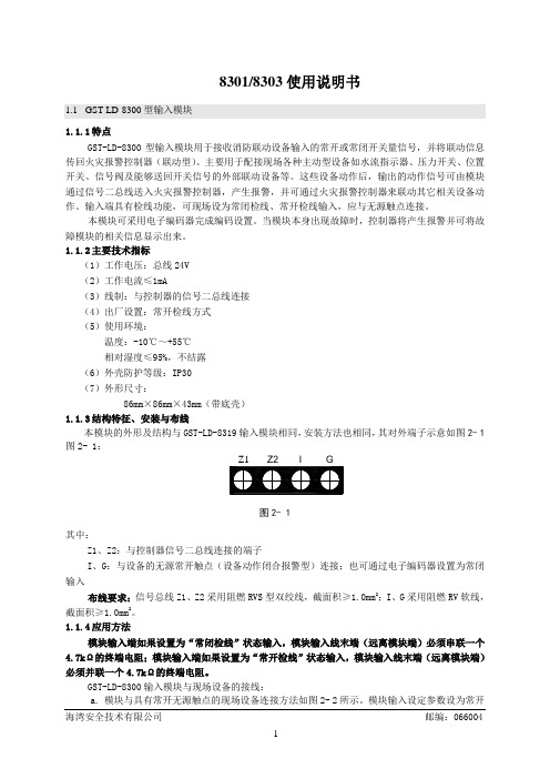
必须并联一个 4.7kΩ的终端电阻。
GST-LD-8300 输入模块与现场设备的接线: a. 模块与具有常开无源触点的现场设备连接方法如图 2- 2 所示。模块输入设定参数设为常开
海湾安全技术有限公司
邮编:066004
1
检线。
Z1 Z2
Z1
Z2
GST-LD-8300
I
G
终端电阻(4.7k)
常开触点 现场设备
输入1 输出1 输入2 输出2
图 2- 9 模块的安装方法与 GST-LD-8319 输入模块相同,其对外端子示意图如图 2- 10:
Z1 Z2 D1 D2 I1 G I2 G S1+ S1- S2+ S2-
图 2- 10
其中: Z1、Z2:接火灾报警控制器信号二总线,无极性 D1、D2:DC24V 电源输入端子,无极性 I1、G:第一路无源输入端(可通过电子编码器设为常开检线、常闭检线、自回答方式) I2、G:第二路无源输入端(可通过电子编码器设为常开检线、常闭检线、自回答方式) S1+、S1-:第一路有源输出端子 S2+、S2-:第二路有源输出端子 布线要求:信号总线 Z1、Z2 采用阻燃 RVS 双绞线,截面积≥1.0mm2;电源线 D1、D2 采用阻燃
直流或交流 (6)输出控制方式:脉冲、电平(继电器常开触点输出或有源输出,脉冲启动时继电器吸合时
间为 10s) (7)出厂设置:常开检线输入、无源输出方式 (8)使用环境: 温度:-10℃~+55℃ 相对湿度≤95%,不结露 (9)外壳防护等级:IP30 (10)外形尺寸: 86mm×86mm×43mm(带底壳)
+24V GND
Z1 Z2
D1 D2 Z1 Z2 GST-LD-8301
欧盟对灯具的安规要求

欧盟对灯具的安规要求Product Safety of LuminairesCE MARK所有的灯具产品都必须符合低电压指令(LVD)及电磁兼容性(EMC)指令,方可进入欧洲市场。
有关CE及GS标志低电压指令(LVD)必须通过EN 60598系列安全标准的测试EN 60598-1:安全通则EN 60598-2-X:特定要求应用标准举例固定式灯具En 60 598-1:1997+A1+A12+A13En 60 598-2-1:1989E.便携式灯具En 60 598-1:1997+A1+A12+A13En 60 598-2-4:1997内装变压器的灯具En 60 598-1:1997+A1+A12+A13En 60 598-2-4:1997En 60 598-2-6:1994+A1便携式儿童感兴趣灯具EN 60 598-1:1997+A1+A12+A13EN 60 598-2-10:1989+A1+A2灯具的危害为什么要进行安全测试?测试是为:-人-财产(物)-环境提供安全保障。
灯具产品可能发生的危害?电击或触电温度过高或引起火灾机械方面存在的危险辐射性危险化学性危险(1)电击或触电接触带有高压的导体接触电源的带有高电压输出端(2) 温度过高或引起火灾接触到灯泡范围内的高温自燃或自爆自燃扩散至其它物品(3) 机械方面存在的危险接触到锋利的边沿接触到旋转部件(如齿轮等)(4)辐射性危险X射线危害IR(红外线)/UV(紫外线)/激光危害本标准适用范围(EN 60598-1)适用于电源电压不超过1000伏的钨丝灯、管形荧光灯和其它气体放电灯的灯具。
规定了机械和电气结构及热的安全要求及相应测试,同时,规定了分类和标识的要求。
本标准中的试验为型式试验1、试验一般选取一个试样进行。
2、若是系列,每一额定功率选一个,或者选一个有代表性的灯具进行试验。
选样包括灯具和附件。
应选最不利的灯具和附件的配合情况。
3. 每一个试样(包括组件)都应承受所有的相应试验。
CE8301

b 、 效率 VS 输出电流:
V0.2
7(9)
升压 超小型 PFM 控制 DC/DC 控制器
封装信息
● SOT-23
CE8301系列
● SOT-89
Symbols
A b b1 b2 C D E E1 θ L L1
Dimensions in millimeters
Min Nom Max
1.40 1.50 1.60
CE8301D 系列产品(SOT-89-5 封装)
符号 NC*1 VOUT
EN
EXT VSS
描述 无连接 输出电压端 开/关控制端: “H”: 通常工作(升压工作) “L”: 停止升压(全部电路停止) 外置晶体管连接端 (CMOS 输出) GND 端
绝对最大额定值
项目
VOUT 端电压 EN 端电压(备有开/关控制功能时)
EN
VOUT NC VSS EXT
描述 开/关控制端: “H”: 通常工作(升压工作) “L”: 停止升压(全部电路停止) 输出电压端 此脚为空,无连接 GND 端 外部电感器连接端 (开路漏极输出) CE8301D系列产品(SOT-23-5封装)
描述 开/关控制端: “H”: 通常工作(升压工作) “L”: 停止升压(全部电路停止) 输出电压端 此脚为空,无连接 GND 端 外置晶体管连接端 (CMOS 输出)
V
1000
mA
250
mW
250
mW
500
mW
-40 ~+85
°C
-40 ~+125
°C
V0.2
3(9)
升压 超小型 PFM 控制 DC/DC 控制器
CE8301系列
电气特性
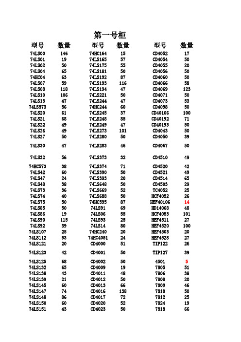
元器件清单
第一号柜型号数量型号数量型号数量74LS0014674HC16415CD405217 74LS011974LS16557CD405450 74LS025074LS17555CD405520 74LS046574LS18150CD405650 74HC046374LS19287CD406050 74LS075974LS193116CD406658 74LS0811874LS19447CD4069123 74LS1010674LS22150CD407150 74LS134774LS24447CD407353 74LS5735674HC24460CD409850 74LS206174LS24537CD40106100 74LS216874LS24885CD4019271 74LS224974LS24947CD4019350 74LS264974LS273101CD404350 74LS275074LS28050CD405039 74LS304774LS28346CD406750 74LS325674LS37332CD451049 74HC5733874LS37471CD452042 74LS426074LS39050CD452149 74LS472474LS39320CD451465 74LS483874LS64850CD450329 74LS733674LS66952TC405225 74LS744074LS68850HCF405226 74LS755074HC59587HEF4010614 74LS855074LS9169HD1406848 74LS861974LS0655HCF4053101 74LS9011574LS9325HEF451127 74LS923974LS1480HEF4520100 74LS1072574HC24020HEF450320 74LS1125374HC405124HEF452827 74LS12120CD400051TIP12226 74LS12342CD400150TIP12739 74LS12568CD40025045015 74LS13265CD400919780551 74LS13843CD401148780638 74LS13921CD401250780820 74LS14560CD401366780946 74LS14774CD4016138781050 74LS14886CD401772781225 74LS15060CD402052782419 74LS15143CD402350781866 74LS15373CD402448790572 74LS15464CD402648790647 74LS15550CD40275079084774LS16069CD40305079093874LS161103CD40404679124274LS163135CD40463079153574LS16437CD405144792419 LM31736LM33757第三号柜型号数量型号数量型号数量晶振(1M)6347P60左右电容683180左右455K1750P200左右1041500左右32.678K7556P160左右224150左右6M6162P150左右33480左右4M2675P120左右474220左右8M8682P180左右10520左右10M27电容101150左右272500左右11.0592M54105100左右9051(NPN)150左右12M53201150左右9011(NPN)80左右20M56221200左右9012(PNP)50左右14.318M6918180左右9013(NPN)100左右24M45271100左右9014(NPN)60左右40M90左右301150左右8550(PNP)100左右10.245M50左右331200左右9018(NPN)100左右80M18391100左右8050(NPN)120左右3.57954523471250左右发光二级管(红)110左右30M有源25501600左右发光二级管(绿)100左右36M有源38511180左右光敏二极管13电容(12P)67561100左右FR307二极管50左右15P50左右681200左右可调电容25-36P70左右3P100左右1021000左右发光二级管(黄)220左右4P100左右821250左右白发红光二极管200左右2.2P100左右122300左右红外发射208P100左右15270左右红外接收29 1P40左右202100左右发光二级管(白)20左右1.5P150左右222160左右发光二级管(双色)80左右5.6P/5.1P100左右302400左右IN60366P/6.8P100左右332180左右稳压二极管2.7V957P/8.2P80左右392100左右稳压二极管2.4V105 9P100左右472180左右IN4732101 10P200左右502120左右IN473049 18P250左右562150左右IN472842 20P180左右682250左右IN472998 22P800左右822150左右IN473395 27P180左右1031500左右IN4734125 30P700左右223200左右IN474429 33P1000左右333300左右IN47354239P750左右473350左右IN414876 IN40010IN4007270左右IN91458第五号柜型号数量型号数量型号数量MSP430F2TPS78001D2THS7001CPWP2 TLC0820AIN27THS4271D22TPS62100D22 AD60313INA137PA2DAC902E31 TLC082IP20DAC781114CX20106A20 OPA2822U40DAC782122MRR2045CTG40 INA213A20CE8301282DW23431 ADS1158202720120TPS6106220 UCC28600D20OPA355UA21117-3.346 TLV5636ID30TPS5416021117-1.830 VCA822ID30PGA113A62390nH100 INA333A82TPS601102470nH80 INA133UA20TPS612002X9312WP36 TLV2462A25TPS601002X9312TP30 ADS828E20ADS788222绕线电阻-36欧10 OPA691ID19ADS523720绕线电阻-30欧6 THS3001ID20VFC32KP22TPS6107020 TPS60310DGS2VCA81037激光二极管40 INA2134PA30INA28220激光接收管10 OPA2134PA35LP2950-33120聚焦透镜10 OPA234020TPS543020ADS111520TPS54331D20CSD17505Q5A15TPS6040020第七号柜型号数量型号数量型号数量AD83512BQ2402517MC337220 ADS834422AT25F51212MC159617 AD836919BUF301200MC164817 ADS850712CNY17-220FDS943120 ADS781820CSI5112PI0MPY6348 AD831020CXA1545AS14MUR15109 AD63716CXA1587S14NCP105020 AD99542CXA169129LM267620 AD71229ATHE8A3260LM290420 AD81130DAC855217LVC424572 AD83424DAC855524KMZ4125 ADS788619DAC900U15HS003819 AD832019DAC902E21LM388610AD84124DAC761116THS450335 AD83024DM9000AE9TL311622 AD84419EXB84115TLC22129 LF412CN35ispPAC805TLC37237 LF35750IR210330MLT0424 74HC57420IR211034MT888018 INA27130MC283328MOC306322 BTA41700B20MC336130MUR166030 BUF634722MC1450770IRF954040 INA12890MC14516323IRF54042 INA15919MC100LVEL6D20TIP32A0 INA233126MC908GP325TIP32C75 INA27034MC1202219IRF530N33 INA233224MAC97A680左右IRF9530N46 BUP30411MC336230IRF63031IRF64046第九号柜型号数量型号数量型号数量CBB102/100V100左右220uF/16V80左右V147-371015490.1uF/630V100左右220uF/250V10V147-391015416 0.47uF/630V100左右47uF/63V50左右二极管SA12A50 220uF/16V50左右47uF/100V100左右P6KE91120 103K/630V100左右100uF/16V120左右IN581752 CD100uF/25V120左右100uF/50V100左右IN582263 100uF/100V80左右330uF/16V80左右贴片9012100左右4.7uF/25V120左右470uF/16V50左右9013100左右4.7uF/50V110左右33uF/250V80左右8050150左右0.1uF/50V30左右47uF/16V100左右8550100左右0.1uF/160V120左右470uF/25V30左右磁环122.2uF/50V80左右1000uF/25V30左右贴片电阻1021500左右3.3uF/16V50左右1000uF/50V100左右贴片电阻0欧100左右4.7uF/250V50左右2200uF/16V60左右软键盘710uF/25V50左右4700uF/16V100左右太阳能控制板147uF/50V100左右2200uF/25V60左右贴片901880左右1uF/50V80左右C92-02恢复二极管30左右1000uF/100V20 100uF/50V30左右D92-02恢复二极管242200uF/100V2010uF/50V15左右变容二极管0-20P30470uF/50V1522uF/25V100左右变容二极管40-75P302200uF/50V2122uF/50V60左右变容二极管400-850P304700uF/50V2322uF/100V23二极管P6KE20020继电器943-1C-6DS2633uF/25V60左右P6KE120105继电器G5RL-1A-E1522uF/250V100左右P6KE15020220uF/450V20第二号柜型号数量型号数量型号数量电位器10126ADS77418OP2745电位器102177AD62029OP3744电位器103107AD770533TL08264电位器104161DAC083233TL08438电位器201150AD65024TL49475电位器202185AD66920TL384210电位器203218AD67719HA1732437电位器204194AD722820CA314058电位器501100AD985124N2567电位器502305AD985274N3551电位器503109MC1403496N13667电位器50448MC1444246N13750电位器253210MC148934P52137拨码开关4P28MC1406035MOC302053拨码开关8P52MC1451649PC81740电机驱动L29725MC1452673NEC2501121电机驱动L29826MC1443320高桥/10A20 BT15118MC14502723LF351116 BT113640MC348631LF35356 D827935NE555116LF35683 82C2920NE55647LF34725 TLP52150NE56461LF39854 D825321NE56769PT226235 D815540NE553292PT227216 80301NE553469ULN200324 80512MICRF002B5ULN280320 AT89C51103MC149622TLC154328 AT89S5117LM3552TLC254328 AT89S5212LM311144TLC551026 AT89C526LM32423TLS752820 AT89C205158LM336(5V)117TLE202219 HY626435LM336(2.5V)50TLV561625 HM6225639LM33928TEB403331 HM61166LM35850TDA282264 M27C12819LM38639TDA705010 GAL20V8B21LM39348HD727910 PIC16C57C6LF56759ST288A48 PIC12C508A16LM741101CH3412 24LC08B35LM187567ICL803840 74HC29524LM290430NB72329 ADC080930LM181217TL07250 ADC083267LM31926TLV246030 AD775123LM33148AD54524ISD256017AD53640ISD25902AD57030FR60722AD57420OP0755AD52618第四号柜型号数量型号数量型号数量C2073(功率管)16ST-ICL319一体化超声波传感器3 3DA87CJ48C181520QM-YT11 3DG800TA7267BP2310214 3DG130DJ107SP203910134 A94020晶闸管1A单硅1810432 KSP290750晶闸管1A双硅1547324 IRF84024EPM72181520442 TIP41C27EP1KTC144220237 TIP42C32EPC2LI20520366 KSP2222A80左右SHT11750240 TL431AC178XF-18D4250143 2DW2331USB转接器150433 2N540150左右热敏电阻75S10KBP31041 2N555140左右NTC10K(+/-)1%9KBPC80855 3D0175左右MYG7K33029KBPC21012 K112035ORD9216302W1013 3DV3330TA122DB106G41 2SC328020热敏电阻10K40左右E623203 DS18B2033C0412直流电机3470K15 BT33P0BPW410光敏电阻34B50K24 BT33FJ40杜邦-IP大量B100K10 DG20135小按键60左右2SK-24118 BBP1020拨码开关50左右K147120 B83472510-2P连接器40左右K51410 D88018人体感应模块163DU3388HM1温度模块149E70518温度传感器73DU310HS1101293DU320HTS11110AN5035C290120CS5125C197020CB35520BB639202SA130125BB11230TDA203023MQ-23ST251C123HY3011RE20015EL-1KL20LM3357SP-1KL0AD59026PT-23F13TCRT500015第六号柜型号数量型号数量型号数量C20790MAX43730MAX76430 C9450MAX50320MAX602920 JGX-5113F3MAX54223OPA12922 nRF24015MAX75632OPA13234 TL07113MAX76526OPA13430 ISD142020MAX80941OPA642u16 CSI511212MAX87431OPA335582SC3423-Y10MAX162620OPA300142SA1360-Y30MAX260120OPA36548 MAX03818MAX26212OPA56136 MAX19517MAX261120OPA60420 MAX20245MAX41065OPA63727 MAX23234MAX740120OPA69016 MAX29120MAX742119OPA222719 MAX323238磁壳绕线电阻器17OPA2270 MAX30620MAX29731OPA22822 MAX40018MAX30927OPA33322编码器2MCR100-630OPA54812 C0721763DG6C20OPA82034 2460C783DG8D20OPA84243射频线3DG182C193CG15C20 OPA656203DG7A20ADS114620第八号柜型号数量型号数量型号数量TL0459TRF37506MCR100-60 TL05230TSAC620022SC520020 TLC08379TLC7135732SC17909 TLC08546TDS2285102SC945100左右TPS7590122THS3091162SC19710 TLV246318安规电容0.1uF80左右应力传感器8 TLV154410安规电容1000pF40左右IN5401100左右SF56208UA73330直流电机30r/分7 MSP430F20027UCC2801926直流电机100r/分0 MSP430F22745UCC38C4322语音编程器2 MSP430F427010UGN35035语音操作WT588D-2010 PM30SSJ06010THS461315超声波发射36 RHRG301200409440超声波接受36SN65LBC184D10C9231282SA194318 SG352520SCA60C-N10000602霍尔开关FQZ-F-NK203 SP322029LM717115中周HGTF10-116 ST18820图像传感器T001P128中周HGTF10-213 ST27817智能控制器2交流接触器1 TPS73301474F15720电机驱动器BAL-352 TPS733335MQ-416电机驱动器DMD402A1 RF2317202SC190644固态继电器SSR-800 TPS3803202SC17910接近开关TK-SN5C3 ADE775517KS10A3 SMA射频插头磁珠29光电探测器10电源变压器19 1W高亮LED50第十号柜型号数量型号数量型号数量数码管LG3641BH38钽电容6.8uF40左右各种DIP座大量TOS-5101BH-B57钽电容22uF80左右LG3641AH23330uH90左右蜂鸣器50左右1uH150左右扬声器0 3.3uH100左右电源插头3210uH80左右9针串口头50左右33uH150左右9孔串口头23贴片68nH80左右电感120uH60左右贴片82nH80左右100uH100贴片0.22uH80左右220uH80左右贴片0.27uH80左右6.8uH/400V250左右 6.8mH110左右470uH120左右 4.7mH120左右680uH100左右10mH25左右12uH110左右100mH50左右15uH100左右色环1mH90左右47uH80左右立式电感1mH80左右56uH100左右立式电感33mH70左右3.3uF/150V50左右排针排座大量100uF/100V50左右IDC座大量10mH100左右连接器大量22uH65左右转接板大量钽电容10uF/25V40左右各种电阻大量钽电容22uF/16V5010000uF/63V20。
CE8301
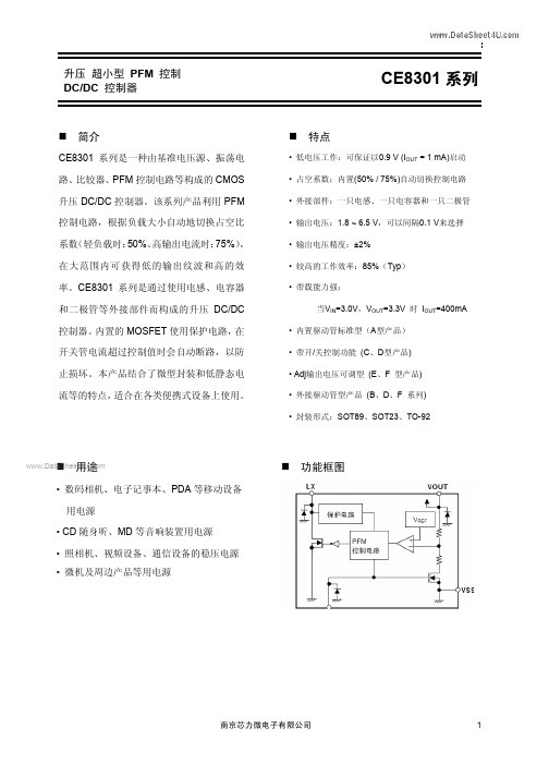
1、 CE8301A常规输出电路(不带EN、FB端):
CE8301系列
2、 CE8301C带EN端输出电路(不带FB端):
3、 CE8301B EXT常规输出电路(不带EN、FB端):
南京芯力微电子有限公司
5
升压 超小型 PFM 控制 DC/DC 控制器 4、 CE8301D EXT带EN端输出电路(不带FB端):
CE8301系列
5、CE8301E 带FB端输出电路(不带EN端):
6、CE8301F EXT带FB端输出电路2(不带EN端):
南京芯力微电子有限公司
6
升压 超小型 PFM 控制 DC/DC 控制器
特征曲线:
1、 CE8301A30P: a、 输出电压 VS 输出电流:
引脚号
1
2 3 4 5
引脚号
1
2 3 4 5
引脚号 1 2 3 4 5
表 3 CE8301C 系列产品(SOT-23-5 封装)
符号
EN
VOUT NC VSS LX 表4 符号
EN
VOUT NC VSS EXT 表5 符号 FB VDD NC VSS LX
描述 开/关控制端: “H”: 通常工作(升压工作) “L”: 停止升压(全部电路停止) 输出电压端 此脚为空,无连接 GND 端 外部电感器连接端 (开路漏极输出) CE8301D系列产品(SOT-23-5封装)
V
1000
mA
250
mW
250
mW
500
mW
-40 ~+85
°C
-40 ~+125
°C
电气特性
项目
符号
条件
CCT8301A 说明书 V2.0版 2013-10-23
CCT-8301A 电导率/TDS/电阻率/温度变送控制器前 言谢您达感使用科瑞制造的CCT-8301A 电导率/TDS/电阻率/温变度送控制器!请详细阅读说书安装前本明,正确电导的池安装参数设会发挥产优势为和置最大限度品的性能和,您带来验很好的使用体。
仪属过测仪应经过训员该专业识员负责此表于精密程分析控表,由培的人或了解和掌握知的人安维装、操作和修。
过难时请时询达术在安装或使用程中遇到困及垂科瑞公司技支持部。
您请务对清单您实际产损请时联达在拆箱后必核成套和所收到的品,如有缺失或坏及系科瑞。
郑诺制造商重承:1.购买内现质问题自之日起一年出量,您将获费产维换得免品修或更新表。
2.论你从购买产对仪诺终术维护务不何渠道本品,制造商售出器承身技之服。
3.对产损围内下列原因造成品的坏不含在保修范之:A、 误电压电损接高源或浸水造成的毁;B、 错误损私自改装和使用造成的毁;C、 选当带损因型不造成的附失;D、 产规条损超出品定的使用件造成的坏;E、 当损不受力造成的所有物理性坏;F、 规仓储运输条标未按照定的或件(引用准SJ/T10463-93储运)造成失效的;G、 购买消耗性材料需要另行。
该号册现时关产别符在手中出,表示涉及有安全、安装、品功能和使用要引起特注意! 与时进俱业发规产会阶级变动请实为是企展的律,品有段性的升,一般恕不另行通知,以物准。
目 录一. 特性及应用 (1)1.1定义 (1)1.2性能及应用 (1)1.3主要技术指标 (2)二. 产品尺寸及电气接线 (3)2.1外形尺寸 (3)2.2端子排定义 (3)2.3毫安变送接线图 (4)2.4电气连接图 (4)2.5电导率高限与控制窗口图解 (5)2.6电阻率低限与窗口控制图解 (7)三. 前面板及按键功能介绍 (7)3.1前面板及主界面示意图 (7)3.2键盘功能介绍 (8)四. 设置与操作 (8)4.1菜单功能介绍 (8)4.2参数查询界面 (10)五. 电导池安装介绍 (11)5.1电导池常数选择 (11)5.2电导池安装及维护保养 (11)5.3型号及外型尺寸 (11)5.4常见的安装方式 (13)六.常见故障判断 (14)七. 产品成套性 (15)八. 定货须知 (15)附录Ⅰ (18)一. 特性及应用1.1 定义1.2 性能及应用z设计理念1)自动化制造装备整合,质量控制目标瞄准零缺陷;2)32位微处理器为核心的强大内核与操作系统,使产品走向IT新时代;3)采用先进的数模混合技术,集电导率/电阻率/温度测量变送/控制一体化整合;4)智能化自动量程无缝衔接,多种计量单位选择和高级链接;5)语言化人机交互界面,引导式操作菜单,人性化流程设计;6)320×240 TFT彩色液晶显示,汉/英双语,多参数同屏显示;7)分级权限密码保护功能,防止非专业人员登陆对工程参数随意修改;8)液晶屏背景照明可以选择长期点亮或延迟休眠,符合低碳时尚;9)触摸感应式操作键盘永无机械疲劳之虞,操作更轻松。
FM8301C
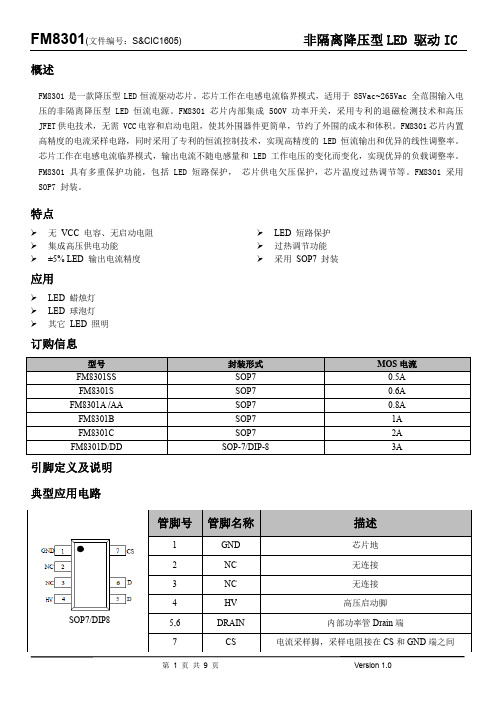
概述FM8301是一款降压型LED恒流驱动芯片。
芯片工作在电感电流临界模式,适用于85Vac~265Vac 全范围输入电压的非隔离降压型LED 恒流电源。
FM8301芯片内部集成 500V 功率开关,采用专利的退磁检测技术和高压JFET供电技术,无需 VCC电容和启动电阻,使其外围器件更简单,节约了外围的成本和体积。
FM8301芯片内置高精度的电流采样电路,同时采用了专利的恒流控制技术,实现高精度的 LED 恒流输出和优异的线性调整率。
芯片工作在电感电流临界模式,输出电流不随电感量和 LED 工作电压的变化而变化,实现优异的负载调整率。
FM8301 具有多重保护功能,包括LED 短路保护,芯片供电欠压保护,芯片温度过热调节等。
FM8301 采用SOP7 封装。
特点无VCC 电容、无启动电阻 集成高压供电功能±5% LED 输出电流精度 LED 短路保护 过热调节功能采用SOP7 封装应用LED 蜡烛灯LED 球泡灯其它LED 照明订购信息引脚定义及说明典型应用电路图1:FM8301典型应用电路推荐工作范围极限参数(注1)注 1:最大极限值是指超出该工作范围,芯片有可能损坏。
推荐工作范围是指在该范围内,器件功能正常,但并不完全保证满足个别性能指标。
电气参数定义了器件在工作范围内并且在保证特定性能指标的测试条件下的直流和交流电参数规范。
对于未给定上下限值的参数,该规范不予保证其精度,但其典型值合理反映了器件性能。
注2:温度升高最大功耗一定会减小,这也是由T JMAX, θJA,和环境温度T A 所决定的。
最大允许功耗为P DMAX = (T JMAX - T A)/θJA 或是极限范围给出的数字中比较低的那个值。
注3:人体模型,100pF 电容通过 1.5KΩ 电阻放电。
电气参数(注 4, 5) (无特别说明情况下,T A =25 ℃)注4:典型参数值为25˚C 下测得的参数标准。
注5:规格书的最小、最大规范范围由测试保证,典型值由设计、测试或统计分析保证。
ufo工矿灯ce标准

UFO工矿灯是一种高效、节能的照明设备,通常用于工业、商业和公共场所
的照明。
CE标准是欧洲共同体(European Community)制定的一系列产品安全和
性能标准,UFO工矿灯要进入欧洲市场,就必须符合CE标准。
UFO工矿灯要符合CE标准,需要满足以下要求:
1. 符合电磁兼容性(EMC)指令要求,包括电磁辐射和抗电磁干扰能力。
2. 符合低电压指令要求,确保工矿灯在使用过程中不会对使用者和其他电
器设备造成电击危险。
3. 符合机械指令要求,确保工矿灯在安装和使用过程中不会对使用者造成
机械伤害。
4. 符合环保指令要求,确保工矿灯在使用过程中不会对环境造成污染。
5. 符合产品安全指令要求,确保工矿灯在使用过程中不会发生电火灾等安
全事故。
为了符合CE标准,UFO工矿灯需要按照CE认证机构的要求进行测试和评估,并获得相应的CE认证证书。
同时,UFO工矿灯还需要在产品上加贴CE认证标志,
以表明产品符合CE标准要求。
车规级mos管

车规级mos管
车规级MOS管是一种适用于汽车电子系统的半导体器件。
以下是一些常见的车规级MOS管的参数和特点:
1. IXFK32N100P:漏极-源极电压为1000V,连续漏电流为32A,功耗为960W,工作结温度范围为-55℃至+150℃,零栅极电压漏极电流为50uA,漏极源导通电阻RDS(ON)为320mΩ,输入电容(CISS)为14.2pF,二极管正向电压为1.5V,反向恢复时间为300ns。
封装尺寸为TO-264,总长度为46.99mm,本体长度为26.16mm,引脚长度为20.83mm,宽度为19.96mm,高度为5.13mm,脚间距为5.46mm。
具有快速本征二极管、国际标准包装、额定无阻尼感应开关(UIS)、低封装电感-易于驱动和保护等特点。
2. IRF9952TRPBF:替代CE8301A33P汽车IC芯片MOS 管。
3. STGB20NB41LZT4:封装D2PAK,汽车MOS管。
4. Infineon/英飞凌 IRFR2905Z:国际整流器MOS场效应管汽车芯片,TO-252原装正品。
此外,还有一些LED汽车驱动mos管、车灯mos管等特殊的车规级MOS管。
在选择和使用这些器件时,需要考虑其参数和特点,以确保其在汽车电子系统中的稳定性和可靠性。
卡瑞恩8301拆机教程

卡瑞恩8301拆机教程
1、拆卸秒轮、过轮和擒纵轮零件,上夹板的两侧有切削槽口供均匀用力撬卸。
然后逐一将秒轮和过轮向上钳离主夹板。
擒纵轮有部分被中夹板和中心轮遮挡,可先将它钳离擒下钻后再横向移出。
2、拆卸手表分轮、跨轮和拨针轮,拆卸分轮可用拿子夹住分轮管向上提拉;也可用镊指钳钳住分轮管中段两侧,以较厚的主夹板为支撑,将它撬离中心轮,使用V形撬棒拆卸分轮亦是如此。
旋去跨轮盖片螺钉后依次钳卸跨轮盖片、跨轮和拨针轮。
3、拆卸手表中夹板,顺时针旋出中夹板的两只螺钉,撬起中夹板,拆掉中心轮。
4、拆卸手表离合杆、柄轴、立轮和离合轮等,旋出压簧螺钉,撬起压簧拆卸之。
用食指部分地遮掩离合杆赞后,另只手将离合杆簧钳离表机(凡拆卸簧类零件务必慎之又慎)。
顺序拆卸离合杆、拉档和拉档轴,柄轴就可抽出,立轮和离合轮会自行落下。
5、拆卸附装在主夹板上的手表防皿器,可参照拆卸摆夹板上防震器的办法进行。
摆下托钻及防震碗拆卸后仍须将防震簧的两瓣逐一装入槽口,以免在清洗主夹板和装置零件时损坏手表零件。
(4)拆卸和安装游丝部件方法。
手表游丝是一根比头发丝还细的极规矩的阿基米德螺旋线弹簧,用温度系数小、弹性系数高,并且耐腐蚀
和防磁的镍铬钛的材质制作而成。
手表游丝内定在表盘内桩上,手表工具的出现外端固定在外柱上,再决定手表活动外柱表盘上。
PS1系列压力控制器说明书

PS1 series pressure controls are designed to limit the pressure for air conditioning, refrigeration, and heat pump applications. The typical application is high or low limit controls. Standard models, ratings, and approvals are listed below. Please contact your sales rep for additonal options.Features PS1• Adjustable pressures and differentials• Narrow adjustable differential depending on model • Range and differential pointer in units bar and psig • Range and differential individually lockable by tab • High rated SPDT contacts for all versions • Captive terminal and cover screws• Manual toggle for system checkout and override Pressure/Temperature High Pressure Ratings:Adjustable Range: 6 - 32 bar (Range 5) 87 - 464 psi 2 - 20 bar (Range 4) 29 - 290 psi Max Working Pressure: 34 bar, 493 psi Burst Pressure: 136 bar, 1972 psi Low Pressure Ratings:Adjustable Range: -0.3 - 7 bar (Range 3) 9”Hg - 102 psi Max Working Pressure: 20 bar, 290 psi Burst Pressure: 80 bar, 1160 psi Temperature Range:-50°C (-58°F) to 70°C (158°F) Ambient/Fluid Materials/ApprovalsMaterials with Media contactFitting Assembly: Brass/Bronze/Cu High Pressure Bellows: Stainless Steel Low Pressure Bellows: Brass/Bronze Aproved Refrigerants HFC, HCFCAgency ApprovalsUL/CUL, File Number E85974TUV (EN12263), CE, CE0035EN-60730-2-6Contact RatingsFLA: 12A at 240VAC, 16A at 120VAC LRA: 72A at 240VAC, 96A at 120VAC Composite Cu/AgNi Contacts #Type RangePressure Logic Pressure Connection Agency PS1-_4_High 2 to 20 bar (29 - 290 psi)Auto Reset • 7/16”-20 UNF (1/4” SAE)• Capillary Tube/Flare Nut • Others AvailableUL/CUL, TUV, OtherPS1-_5_ 6 to 32 bar (87 - 464 psi Manual Reset PS1-_3_Low-0.3 to 7 bar (9”Hg - 102 psi)Auto ResetHigh Pressure Contact StructureSPDT (11-12 Motor Load, 11-14 Signal Load)Low Pressure Contact StructureSPDT (11-14 Motor Load, 11-12 Signal Load)HP AlarmNormal HP AlarmNormalPS2 series pressure controls are designed to limit the pressurefor air conditioning, refrigeration, and heat pump applications.The typical application is high or low limit controls. Standardmodels, ratings, and approvals are listed below. Please contactyour sales rep for additonal options.Features PS2• Adjustable pressures and differentials• Narrow adjustable differential depending on model• Range and differential pointer in units bar and psig• Range and differential individually lockable by tab• High rated SPDT contacts for all versions• Captive terminal and cover screws• Manual toggle for system checkout and overridePressure/TemperatureHigh Pressure Ratings:Adjustable Range: 6 - 32 bar (Range 7)87 - 464 psiMax Working Pressure: 34 bar, 493 psiBurst Pressure: 136 bar, 1972 psiLow Pressure Ratings:Adjustable Range: -0.3 - 7 bar (Range 3)9”Hg - 102 psiMax Working Pressure: 20 bar, 290 psiBurst Pressure: 80 bar, 1160 psiTemperature Range:-50°C (-58°F) to 70°C (158°F) Ambient/FluidMaterials/ApprovalsMaterials with Media ContactFitting Assembly: Brass/Bronze/CuHigh Pressure Bellows: Stainless SteelLow Pressure Bellows: Brass/BronzeAproved RefrigerantsHFC, HCFCAgency ApprovalsUL/CUL, File Number E85974TUV (EN12263), CE, CE0035EN-60730-2-6Contact RatingsFLA: 12A at 240VAC, 16A at 120VACLRA: 72A at 240VAC, 96A at 120VACComposite Cu/AgNi Contacts#Type Range Pressure Logic Pressure Connection AgencyPS2Dual,Auto orManualResetLow Side:-0.3 to 7 bar (9”HG to 102 psi)Auto ResetManual• 7/16”-20 UNF (1/4” SAE)• Capillary Tube/Flare Nut• Others AvailableUL/CUL, TUV, Other High Side:6 to 32 bar (87 - 464 psi)Normal Operation Contacts 11-14, 21-22 Motor Load Contacts 11-12, 21-24 Signal LoadLP AlarmLow Pressure Cut-OutContacts 11-14 OpenHP Alarm。
GST-LD-IE8301输入-输出模块安装使用说明书

一、概述GST-LD-IE8301输入/输出模块(以下简称模块),是一款功能强大、应用广泛的编码工业模块。
模块可以通过设置不同的工作模式,实现下列功能:启动消防联动设备,如排烟阀、送风阀、防火阀等,同时接收设备的动作回答信号模块不能用于气体灭火设备的控制。
模块符合GB 16806-2006中的相关规定。
二、特点1. 抗电磁干扰能力卓越。
2. 可直接控制交流220V供电设备。
3. 输入输出端均有检线功能。
4. 工作模式可通过电子编码器设置,以实现不同的功能。
5. 地址码为电子编码,可由电子编码器设置,也可由控制器更改,工程调试灵活简便。
三、技术特性1. 工作电压•总线电压:24V 允许范围:16V~28V;•电源电压:DC24V 允许范围:DC20V~DC28V。
2. 工作电流•总线电流≤0.6mA;•电源监视电流≤15mA。
3. 输出•继电器输出:一组常开/常闭触点,容量为AC220V/5A或DC30V/5A;•DC24V输出:最大输出电流为1A。
4. 指示•输入指示灯:红色,正常监视状态闪亮,有输入信号时点亮;•输出指示灯:红色,启动输出时点亮,其它状态熄灭。
5. 编码方式电子编码方式,占用一个总线编码点,编码范围可在1~242之间任意设定。
6. 工作模式:共有3种工作模式,可通过设置不同的参数来选择工作模式。
7. 使用环境•温度:-40℃~+70℃•相对湿度≤95%,不凝露•可室外使用8.壳体材料:压铸铝合金9.外形尺寸:195mm×275mm×86mm10.防护等级:IP6711.安装孔距:185mm(不使用安装板)或255mm(使用安装板),参见图2、3。
12.重量:1.87kg四、结构特征与工作原理1. 模块外形示意图如图1所示。
图1 外形示意图2. 工作原理模块内嵌两个微处理器,其中一个微处理器用于与火灾报警控制器通讯:接收火灾报警控制器的启动、复位等命令以及将模块当前的状态上传给火灾报警控制器。
FM8301D

FM8301D
第 1 页 共 1 页 Version 1.0
概述
FM8301是一款降压型LED 恒流驱动芯片。
芯片工作在电感电流临界模式,适用于85Vac ~265Vac 全范围输入电压的非隔离降压型LED 恒流电源。
FM8301芯片内部集成 500V 功率开关,采用专利的退磁检测技术和高压 JFET 供电技术,无需 VCC 电容和启动电阻,使其外围器件更简单,节约了外围的成本和体积。
FM8301芯片内置高精度的电流采样电路,同时采用了专利的恒流控制技术,实现高精度的 LED 恒流输出和优异的线性调整率。
芯片工作在电感电流临界模式,输出电流不随电感量和 LED 工作电压的变化而变化,实现优异的负载调整率。
FM8301 具有多重保护功能,包括LED 短路保护, 芯片供电欠压保护,芯片温度过热调节等。
FM8301 采用 SOP7 封装。
特点
无 VCC 电容、无启动电阻 集成高压供电功能 ±5% LED 输出电流精度
LED 短路保护
过热调节功能 采用 SOP7 封装
应用
LED 蜡烛灯 LED 球泡灯 其它 LED 照明
订购信息
引脚定义及说明。
PAM8301中文资料

PAM8301中文资料Key FeaturesApplications1.5W Output at 10%THD with a 8Loadand 5V Power SupplyFilterless,Low Quiescent Current and LowEMIHigh Efficiency up to 88%Superior Low Noise Short Circuit Protection Thermal ShutdownFew External Components to Save Spaceand CostTiny SOT23-6Package PMP/MP4GPSPortable Speakers Walkie TalkieHandsfree phones/Speaker Phones Cellular Phonesdirectly system cost It can optimize battery life thus is ideal for portable applications.Ωn n n n n nGeneral DescriptionThe PAM8301is a 1.5W class-D mono audio amplifier.Its low THD+N feature offers high-quality sound reproduction.The new filterless architecture allows the device to drive speaker instead of using low-pass output filters,therefore save and PCB area.With the same number of external components,the efficiency of the PAM8301is much better than that of class-AB cousins.The PAM8301is available in SOT23-6package.n n n n n n n n n Pb-Free PackageTypical ApplicationShutdownAudioBlock DiagramPin Configuration &Marking InformationTOP VIEW SOT23-6654123FPXYWFP:Product Code of PAM8301X:Internal Code Y:Year W:WeekINSD-OUT+OUT GNDVDDAbsolute Maximum RatingsThese are stress ratings only and functional operation is not implied Exposure to absolute maximum ratings for prolonged time periods may affect device reliability All voltages are with respect to ground ...Supply Voltage at no Input Signal...................6.6V Storage Temperature.....................-65to 150Soldering Temperature......................Input Voltage.............................-0.3V to V +0.3VMaximum Junction Temperature..................150°C °C °C 300°C,5secDD Recommended Operating ConditionsSupply voltage Range........................Operation Temperature Range........-40to 85Junction Temperature Range.........-40to 1252.5V to 5.5V Max.Supply Voltage (for Max.duration of30minutes)................................................6.0V°C °C °C °CThermal InformationElectrical CharacteristicV =5V,Gain =24dB,R =8T =25unless otherwise noted. DD L A Ω,,°CTypical Performance CharacteristicT =25°C,unless otherwise noted.A 3.Efficiency VS Output Power5.THD+N VS Output Power60%65%70%75%80%85%90%95%100%020040060080010001200Output Pow er(m W)E f f i c i e n c y000%20m350m 100m 200m500m 12W% 050100150200250300350020406080100120140T em p eratu reF r e q u e n c y (k H z )1.Frequency VS Supply Voltage2.Frequency VS Temperature 238 240242244246248250252 25425625823456Supply Voltage (V)F r e q u e n c y (k H z )4.Efficiency VS Output Power 6.THD+N VS Output Power20m350m 100m 200m500m 12W50%55%60%65%70%75%80%85%90%200400600800100012001400160018002000Output P ow er (m W)E f f i c i e n c yTypical Performance Characteristic T =25°C,unless otherwise noted.A 7.THD+N VS Frequency2020k501002005001k2k5k10kHz11.Frequency Response12.Noise Floord BV 2020k501002005001k 2k 5k 10k Hz %2020k501002005001k 2k 5k 10k Hz8.THD+N VS Frequency9.THD+N VS Frequency10.THD+N VS Frequency2020k501002005001k 2k 5k 10k Hz+++++++++d B r A2020k501002005001k 2k 5k 10k Hz%2020k501002005001k 2k 5k 10k HzTypical Performance CharacteristicT =25°C unless otherwise noted.A 13.PSRR14.EMI vs Frequency.-+0---------d B2010k501002005001k 2k 5k HzR =8L Ω,Gain=23dB,V =5V,Po=500DD mW Test Setup for Performance Testing1.The AP AUX-0025low pass filter is necessary for every class-D amplifier measurement with AP analyzer.2.Two 22μH inductors are used in series with load resistor to emulate the small speaker for efficiency measurement.PAM8301Demo BoardApplication InformationMaximum GainAs shown in block diagram (page 2),the PAM8301has two internal amplifier stages.The first stage's gain is externally configurable,while the second stage's is internally fixed.The closed-loop gain of the first stage is set by selecting the ratio of R to R while the second stage's gain is fixed at 2x.The output of amplifier 1serves as the input to amplifier 2,thus the two amplifiers produce signals identical in magnitude,but different in phase by 180°.Consequently,the differential gain for the IC isA =20*log [2*(R /R )]The PAM8301sets maximum R =80k ,minimum R =10k ,so the maximum closed-gain is 24dB.f i VD f i f i ΩΩInput Capacitors (Ci)Power Supply Decoupling (Cs)Shutdown OperationFor the best power on/off pop performance,the amplifier should be set in the shutdown mode prior to power on/off operation.Under Voltage Lock-out (UVLO)In typical application,an input capacitor,Ci,is required to allow the amplifier to bias input signals to a proper DC level for optimum operation.In this case,Ci and the minimum input impedance Ri (10k internal)form a high pass filter with a corner frequency determined by the following equation:It is important to choose the value of Ci as it directly affectslow frequency performance of the circuit,for example,when an application requires a flat bass response as low as 100Hz.Equation is reconfigured as follows:As the input resistance is variable,for the Ci value of 0.16F,one should actually choose the Ci within the range of 0.1F to 0.22 F.A further consideration for this capacitor is the leakage path from the input source through the input network (Ri,RF,Ci)to the load.This leakage current creates a DC offset voltage at the input to the amplifier that reduces useful headroom,especially in high gain application.For this reason,a low leakage tantalum or ceramiccapacitor is the best choice.When a polarized capacitor is used,the positive side of the capacitor should face the amplifier input in most applications as the DC level is held at VDD/2,which is likely higher than the source DC level.Please note that it is important to confirm the capacitor polarity in the application.The PAM8301is a high-performance CMOS audio amplifier that requires adequate power supply decoupling to ensure the output THD and PSRR as low as possible.Power supply decoupling affects low frequency response.Optimum decoupling is achieved by using two capacitors of different types that target different types of noise on the power supply leads.For higher frequency transients,spikes,or digital hash on the line,a good low equivalent-series-resistance (ESR)ceramic capacitor,typically 1.0μF is good,placing it as close as possible to the device VDD terminal.For filtering lower-frequency noise signals,a capacitor of 10μF orlarger,closely located to near the audio power amplifier is recommended.In order to reduce shutdown power consumption,the PAM8301contains shutdown circuitry for turnoff the amplifier.This shutdown feature turns the amplifier off when a logic low is applied on the SHDOWN pin.By switching the shutdown pin over to GND,the PAM8301supply current draw will be minimized in idle mode.The PAM8301incorporates circuitry to detect low on or off voltage.When the supply voltage drops to 2.1V or below,the PAM8301goes into a state of shutdown,and the device comes out of its shutdown state and starts to normal operation by reset the power supply or pin.μμμSD ()C 1f 2RiCi p =()i c 1Ci 2R f p =How to Reduce EMI (Electro Magnetic Interference)A simple solution is to put an additional capacitor 1000F at power supply terminal for power line coupling if the traces from amplifier to speakers are short (<20cm).Most applications require a ferrite bead filter as shown at Figure 1.The ferrite filter depresses EMI of around 1MHz and higher.When selecting a ferrite bead,choose one with high impedance at high frequencies and low impedance at low frequencies.Figure 1:Ferrite Bead Filter to Reduce EMIμOrdering InformationPAM8301Pin ConfigurationNumber of pins Pin TypeSOT23-6Outline DimensionsGAUGE PLANE SEATING PLANE PLANTINGBASE SECTION A-ASEE VIEWSUnit:Millimeter。
gp8301手册
GP8301是一款高精度、高稳定性的压力传感器,广泛应用于各种工业自动化控制系统中。
本手册将详细介绍GP8301的性能参数、工作原理、安装方法以及使用注意事项等内容,帮助用户更好地理解和使用该产品。
首先,GP8301具有优异的性能参数。
其测量范围广,可达到0-100kPa;精度等级高,误差小于±0.5%FS;响应速度快,仅为0.2秒;长期稳定性好,年漂移量小于0.1%FS。
此外,GP8301还具有抗干扰能力强、过载能力强等特点。
其次,GP8301的工作原理是利用半导体压力敏感元件将压力信号转换为电信号输出。
当被测介质作用于压力敏感元件时,其电阻值发生变化,通过电路将电阻变化转换为电压或电流输出,从而实现对压力的测量和控制。
在安装GP8301时,需要注意以下几点:1)选择合适的安装位置,避免受到振动、冲击等影响;2)确保连接管路无泄漏现象;3)正确接线,避免接错线导致设备损坏或误操作。
最后,在使用GP8301时,应注意定期进行校准和维护,以确保其正常工作和延长使用寿命。
同时,在使用过程中遇到问题时,应及时联系厂家或专业人员进行处理。
采用D类功放IC的FM收音读卡音箱PCB Layout布线注意事项
采用D类功放IC的FM收音读卡音箱PCB Layout布线注意事项功放, 音箱, 注意事项调频(FM)接收机在读卡迷你音箱和便携式播放器中已经开始广泛应用了,它能提供极佳的音质、讯号稳定性和抗噪声能力。
近来FM接收机已开始出现在更多的行动和个人媒体播放器等市场应用中,为了电池续航力,在后级功率放大器选用上,D类功放IC与FM收音的结合是不可避免的趋势。
关于带FM收音的插卡式(便携)音箱,大致总结了关于此类系统的总体框架。
相关模块已尽可能多的列出,可根据具体系统实际情况删减。
图1 带FM收音功能读卡音箱结构框图上述模块相关芯片型号列举:MCU (Mp3 Decoder): 炬力ATS2503,山景AU6850C,建荣AX2000,士兰SC3680,凌阳FM: RDA5807, PL102RT-S, KT0830EGMemory: EEPROM, 24C02, 256×8 bitsFlash, W25×16, 16M bitsPower: Li Bat Charger, EUP8054, CYT4054DC-DC升压,ME2108, CE8301, TP8350, LP3120采用D类功放IC的读卡音箱PCB Layout布线注意事项:1、D类功放IC音频输入方式MCU (MP3 Decoder), FM输出的Audio信号基本为单端信号(如果是差分信号输入方式,可抑制大量差模噪声),需考虑此类系统的噪声问题。
包括地线处理、整体布局的考虑对噪声的影响以及pop声的抑制考虑等。
(1)输入方式。
如果采用差分方式,可滤除共模噪声,所以有较佳的噪声抑制能力。
图2 D类功放IC差分输入原理图(2)电源、地线处理。
数字地与模拟地的隔离,D类功放IC PGND与AGND的隔离(由于PVDD、PGND处受内部功率管频繁开关而受干扰,有一定噪声)都会有一定的作用;地环路产生的噪声,比如电源与音源同为PC机提供,PC机上较大噪声会引入,此时采用差分输入切断地环路会有很大效果;PVDD与PGND间至少需添置一个尽量靠近这两个引脚的1uF电容;另外,外部电源、DC-DC电源、锂电池充电等也会容易引入噪声,亦需谨慎处理。
cpci-8301 3u compactpci 64-bit pmc carrier board u

Advance Technologies; Automate the World.Manual Rev.2.00Revision Date:November 1, 2004Part No:50-15024-100cPCI-83013U CompactPCI64-bit PMC Carrier BoardUser’s ManualCopyright 2004 ADLINK TECHNOLOGY INC.All Rights Reserved.The information in this document is subject to change without prior notice in order to improve reliability, design, and function and does not represent a commitment on the part of the manufacturer.In no event will the manufacturer be liable for direct, indirect, spe-cial, incidental, or consequential damages arising out of the use or inability to use the product or documentation, even if advised of the possibility of such damages.This document contains proprietary information protected by copy-right. All rights are reserved. No part of this manual may be repro-duced by any mechanical, electronic, or other means in any form without prior written permission of the manufacturer. TrademarksProduct names mentioned herein are used for identification pur-poses only and may be trademarks and/or registered trademarks of their respective companies.Getting Service from ADLINK Customer Satisfaction is top priority for ADLINK Technology Inc. Please contact us should you require any service or assistance.ADLINK TECHNOLOGY INC.Web Site:Sales & Service:**********************TEL:+886-2-82265877FAX:+886-2-82265717Address:9F, No. 166, Jian Yi Road, Chungho City,Taipei, 235 TaiwanPlease email or FAX this completed service form for prompt and satisfactory service.Company InformationCompany/OrganizationContact PersonE-mail AddressAddressCountryTEL FAX:Web SiteProduct InformationProduct ModelEnvironment OS:M/B: CPU: Chipset: BIOS:Please give a detailed description of the problem(s):Table of ContentsList of Tables (ii)List of Figures (iii)1Introduction (1)1.1Product Overview (1)1.2Unpacking Checklist (2)1.3cPCI-8301 Mechanical Drawing (3)1.4cPCI-8301 Functional Diagram (4)1.5cPCI-8301 Placement (4)1.6Number of Boards Supported per PCI Bus (5)2Connectors (7)2.1PMC Connectors (7)2.2CompactPCI Connectors (10)Warranty Policy (13)Table of Contents iList of TablesTable 2-1:P1 and P2 PMC Connector Pin Definitions (7)Table 2-2:P3 PMC Connector Pin Definitions (8)Table 2-3:J1 Connector Pin Definitions (10)Table 2-4:J2 Connector Pin Definitions (64-bit) (11)ii List of TablesList of FiguresFigure 1-1:cPCI-8301 Carrier Board Layout (3)Figure 1-2:cPCI-8301 Functional Diagram (4)Figure 1-3:cPCI-8301 Top View (4)Figure 1-4:cPCI-8301 Bottom View (5)List of Figures iiiivIntroduction 11Introduction1.1Product OverviewThe cPCI-8301 is a standard 3U form factor CompactPCI 64-bit PMC carrier board with one PMC site. It supports 32/64-bit,33/66MHz PCI buses. It is PICMG 2.0 CompactPCI Specification R2.1 and IEEE 1386.1 PMC Standard compliant.Note :There is no VIO keying on the cPCI-8301. VIO is directly connected to connector J2 and defined by the backplane.Please check your backplane’s VIO before installing your PMC card onto the cPCI-8301.2Introduction 1.2Unpacking ChecklistCheck the shipping carton for any damage. If the shipping carton and contents are damaged, notify the dealer for a replacement.Retain the shipping carton and packing materials for inspection by the dealer. Obtain authorization before returning any product to ADLINK.Check the following items are included in the package, if there are any items missing, please contact your dealer:Included Items cPCI-8301 carrier board This manual Note:The packaging of the cPCI-8301 OEM version with non-standard configuration, functionality, or packagemay vary according to different configuration requests.CAUTION:The cPCI-8301 carrier board must be protected fromstatic discharge and physical shock. Never remove any of the socketed parts except at a static-free work-station. Use the anti-static bag shipped with the prod-uct to handle the board. Wear a grounded wrist strap when servicing.1.3cPCI-8301 Mechanical DrawingFigure 1-1: cPCI-8301 Carrier Board LayoutIntroduction 31.4cPCI-8301 Functional DiagramFigure 1-2: cPCI-8301 Functional Diagram1.5cPCI-8301 PlacementFigure 1-3: cPCI-8301 Top View4IntroductionIntroduction 5Figure 1-4: cPCI-8301 Bottom View1.6Number of Boards Supported per PCI BusThe maximum number of cPCI-8301 boards that can be supported on one PCI bus is dependant on the frequency of the PMC cards installed. Please refer to the following table:Note:If one or more 33MHz PMC cards is installed, all cards will run at 33MHz, and this will determine the maximum number of boards supported.PMC Card frequency 33MHz 66MHzNumber of Boards on one PCI bus426Introduction2ConnectorsThis chapter will familiarize the user with the connectors on the cPCI-8301.2.1PMC ConnectorsThe cPCI-8301 is a single I/O board for 64-bit PMC to cPCI trans-fer. PMC connectors P1-P3 are implemented. The P4 connector (User IO) is not implemented.The Jn1, Jn2, and Jn3 PMC connector pin definitions are shown in the following tables:Jn1 (32 Bit)Jn2 (32Bit)Pin Signal Signal Pin Pin Signal Signal Pin 1TCK-12V21+12V TRST#2 3GND INTA#43TMS TDO4 5INTB#INTC#65TDI GND6 7NC+5V87GND NC8 9INTD#NC109NC NC10 11GND NC1211BUSMODE2#+3.3V12 13CLK GND1413RST#BUSMODE3#14 15GND GNT#1615+3.3V BUSMODE4#16 17REQ#+5V1817NC GND18 19V(I/O)AD[31]2019AD[30]AD[29]20 21AD[28]AD[27]2221GND AD[26]22 23AD[25]GND2423AD[24]+3.3V24 25GND C/BE[3]#2625IDSEL AD[23]26 27AD[22]AD[21]2827+3.3V AD[20]28 29AD[19] +5V3029AD[18]GND30 31V(I/O)AD[17]3231AD[16]C/BE[2]#32 33FRAME#GND3433GND NC34 35GND IRDY#3635TRDY#+3.3V36 37DEVSEL#+5V3837GND STOP#38 Table 2-1: P1 and P2 PMC Connector Pin DefinitionsConnectors 78ConnectorsNote:For pins 11, 14 and 16 of Jn2, BUSMODE is set to capable of performing PCI protocol :39GND LOCK#4039PERR#GND 4041NC NC 4241+3.3V SERR#4243PAR GND 4443C/BE[1]#GND 4445V(I/O)AD[15]4645AD[14]AD[13]4647AD[12]AD[11]4847M66EN AD[10]4849AD[09]+5V 5049AD[08]+3.3V 5051GND C/BE[0]#5251AD[07]NC 5253AD[06]AD[05]5453+3.3V NC 5455AD[04]GND 5655PMC-RSVD1GND 5657V(I/O)AD[03]5857PMC-RSVD2PMC-RSVD35859AD[02]AD[01]6059GND PMC-RSVD46061AD[00]+5V 6261ACK64#+3.3V 6263GNDREQ64#6463GNDNC64BUSMODE[4:2]#L L HJn3 (64 Bit)Pin Signal Signal Pin 1NC GND 23GND C/BE[7]#45C/BE[6]#C/BE[5]#67C/BE[4]#GND 89V(I/O)PAR641011AD[63]AD[62]1213AD[61]GND 1415GNDAD[60]16Table 2-2: P3 PMC Connector Pin DefinitionsJn1 (32 Bit)Jn2 (32Bit)Pin Signal Signal Pin Pin Signal Signal Pin Table 2-1: P1 and P2 PMC Connector Pin DefinitionsJn3 (64 Bit)Pin Signal Signal Pin17AD[59]AD[58]1819AD[57]GND2021V(I/O)AD[56]2223AD[55]AD[54]2425AD[53]GND2627GND AD[52]2829AD[51]AD[50]3031AD[49]GND3233GND AD[48]3435AD[47]AD[46]3637AD[45]GND3839V(I/O)AD[44]4041AD[43]AD[42]4243AD[41]GND4445GND AD[40]4647AD[39]AD[38]4849AD[37]GND5051GND AD[36]5253AD[35]AD[34]5455AD[33]GND5657V(I/O)AD[32]5859NC NC6061NC GND6263GND NC64Table 2-2: P3 PMC Connector Pin Definitions Connectors 92.2CompactPCI ConnectorsThe J1 and J2 CompactPCI connector definitions are shown in thetables below:J1Pin A B C D E F J1-25+5V REQ64#NC+3.3V+5V GND J1-24AD[1]+5V VIO AD[0]ACK64#GND J1-23+3.3V AD[4]AD[3]+5V AD[2]GND J1-22AD[7]GND+3.3V AD[6]AD[5]GND J1-21+3.3V AD[9]AD[8]GND C/BE[0]#GND J1-20AD[12]GND VIO AD[11]AD[10]GND J1-19+3.3V AD[15]AD[14]GND AD[13]GND J1-18SERR#GND+3.3V PAR C/BE[1]#GND J1-17+3.3V PMC-RSVD3PMC-RSVD4GND PERR#GND J1-16DEVSEL#GND VIO STOP#LOCK#GND J1-15+3.3V FRAME#IRDY#GND TRDY#GND J1-12-14Keying AreaJ1-11AD[18]AD[17]AD[16]GND C/BE[2]#GND J1-10AD[21]GND+3.3V AD[20]AD[19]GND J1-9C/BE[3]#IDSEL AD[23]GND AD[22]GND J1-8AD[26]GND VIO AD[25]AD[24]GND J1-7AD[30]AD[29]AD[28]GND AD[27]GND J1-6REQ#GND+3.3V CLK AD[31]GND J1-5NC NC RST#GND GNT#GND J1-4PMC-RSVD1NC VIO NC PMC-RSVD2GND J1-3INTA#INTB#INTC#+5V INTD#GND J1-2TCK+5V TMS TDO TDI GND J1-1+5V-12V TRST#+12V+5V GND Table 2-3: J1 Connector Pin Definitions10ConnectorsJ2 (64-bit)Pin A B C D E FJ2-22NC NC NC NC NC GNDJ2-21NC NC NC NC NC GNDJ2-20NC NC NC GND NC GNDJ2-19NC NC NC NC NC GNDJ2-18NC NC NC GND NC GNDJ2-17NC GND NC NC NC GNDJ2-16NC NC NC GND NC GNDJ2-15NC GND NC NC NC GNDJ2-14AD[35]AD[34]AD[33]GND AD[32]GNDJ2-13AD[38]GND VIO AD[37]AD[36]GNDJ2-12AD[42]AD[41]AD[40]GND AD[39]GNDJ2-11AD[45]GND VIO AD[44]AD[43]GNDJ2-10AD[49]AD[48]AD[47] GND AD[46]GNDJ2-9AD[52]GND VIO AD[51]AD[50]GNDJ2-8AD[56]AD[55]AD[54]GND AD[53]GNDJ2-7AD[59]GND VIO AD[58]AD[57]GNDJ2-6AD[63]AD[62]AD[61]GND AD[60]GNDJ2-5C/BE[5]#GND VIO C/BE[4]#PAR64GNDJ2-4VIO NC C/BE[7]#GND C/BE[6]#GNDJ2-3NC GND NC NC NC GNDJ2-2NC NC NC NC NC GNDJ2-1NC GND NC NC NC GNDTable 2-4: J2 Connector Pin Definitions (64-bit) Connectors 1112ConnectorsWarranty Policy 13Warranty PolicyThank you for choosing ADLINK. To understand your rights and enjoy all the after-sales services we offer, please read the follow-ing carefully.1.Before using ADLINK’s products please read the user manual and follow the instructions exactly. When sending in damaged products for repair, please attach an RMA application form which can be downloaded from:/policy/.2.All ADLINK products come with a two-year guarantee:X The warranty period starts from the product’s shipment date from ADLINK’s factory.X Peripherals and third-party products not manufactured by ADLINK will be covered by the original manufacturers'warranty.X For products containing storage devices (hard drives,flash cards, etc.), please back up your data before send-ing them for repair. ADLINK is not responsible for loss of data.X Please ensure the use of properly licensed software with our systems. ADLINK does not condone the use of pirated software and will not service systems using such software. ADLINK will not be held legally responsible for products shipped with unlicensed software installed by the user.X For general repairs, please do not include peripheral accessories. If peripherals need to be included, be cer-tain to specify which items you sent on the RMA Request & Confirmation Form. ADLINK is not responsible for items not listed on the RMA Request & Confirmation Form.14Warranty Policy 3.Our repair service is not covered by ADLINK's two-year guarantee in the following situations:X Damage caused by not following instructions in the user's manual.X Damage caused by carelessness on the user's part during product transportation.X Damage caused by fire, earthquakes, floods, lightening,pollution, other acts of God, and/or incorrect usage of voltage transformers.X Damage caused by unsuitable storage environments (i.e.high temperatures, high humidity, or volatile chemicals).X Damage caused by leakage of battery fluid during or after change of batteries by customer/user.X Damage from improper repair by unauthorized techni-cians.X Products with altered and/or damaged serial numbers are not entitled to our service.X Other categories not protected under our warranty.4.Customers are responsible for shipping costs to transport damaged products to our company or sales office.5.To ensure the speed and quality of product repair, please download an RMA application form from our company web-site: /policy. Damaged products with attached RMA forms receive priority.If you have any further questions, please email our FAE staff: **********************.。
