ADY13 design SPEC
AD-013指纹识别模块数据手册说明书

[DESCRIPTION]The AD-013 fingerprint sensor module is consist from a fingerprint sensor & a MCU. The module provide one UART interface output port for connecting to customer side main board.The operation of AD-013 is as following, a fingerprint image captured by pixel array, delivery fingerprint ridge or valley signals to A/D converter and digital processor, then to the serial peripheral interface for data-reading. Due to MCU already installed fingerprint algorithm, the user can through UART interface use MCU SOC command to operate module like fingerprint enroll, match operations etc. [FEATURES]●160x160 pixels●Build-in ADC for digitizing image●UART interface●Data encryption●Short read out time●Cost effective sensor●High sensing capability ●Single power supply[APPLICATIONS]●Door lock●Security device●Access control systemTable of Contents1Electrical Characteristics (4)1.1Maximum rating (4)1.2Operation condition (4)2Specification (5)3Mechanical Specification (6)3.1Connector Information (6)3.2Package size (6)3.3Outline Reference (7)4SDK Guide (7)4.1UART setting (7)4.2Initial time (7)4.3Command protocol (7)4.4Response time (7)5Revision history (8)1 Electrical Characteristics2 SpecificationSensing area 8mm x 8mmSensing array 160 x 160 pixelsPackage size 29mm x 19.6mm x 6.06mm(H) Gray Level 8 bits/pixels ,256 gray scales Recognition Time 1:N , < 0.6 second Template capacity 40FRR(False Rejection Rate) 6%FAR(False Acceptance Rate) <0.01‰Interface UART (57600,8,N,2) / TTL level Supply voltage 3.3VTotal supply current 40mAOperating Humidity 0 - 95% , Non-condense Operating temperature -20 to +70 ⁰CESD protection for air discharging 8kV3 Mechanical Specification3.2 Package size29mm x 19.6mm x 6.06 mm(H)3.3 Outline Reference4 SDK Guide4.1 UART settingUART default baud rate : 57600Data format: 8 bits of data, No parity, 2 stop bits4.2 Initial timeAfter Power on, the module initial time about 50ms.Module will send 0x55 data to Host by UART TX after initial finish. The module would not response Host command at initial time. 4.3 Command protocolPlease refer the SOC Manual document.4.4 Response timeThe normal command response time list as below table5 Revision history。
altiumdesigner13安装教程
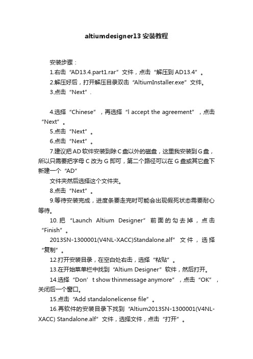
altiumdesigner13安装教程安装步骤:1.右击“AD13.4.part1.rar”文件,点击“解压到AD13.4”。
2.解压好后,打开解压目录双击“AltiumInstaller.exe”文件。
3.点击“Next”.4.选择“Chinese”,再选择“l accept the agreement”,点击“Next”。
5.点击“Next”。
6.点击“Next”。
7.建议把AD软件安装到除C盘以外的磁盘,这里我安装到G盘,所以只需要把字母C改为G即可,第二个路径可以在G盘或其它盘下新建一个“AD”文件夹然后选择这个文件夹。
8.点击“Next”。
9.等待安装完成,进度条要走完时可能会出现假死状态需要耐心等待。
10.把“Launch Altium Designer”前面的勾去掉,点击“Finish”。
2013SN-1300001(V4NL-XACC)Standalone.alf”文件,选择“复制”。
12.打开安装目录,在空白处右击,选择“粘贴”。
13.在开始菜单栏中找到“Altium Designer”软件,然后打开。
14.选择“Don’t show thinmessage anymore”,点击“OK”,关闭后一个窗口。
15.点击“Add standalonelicense file”。
16.再软件的安装目录下找到“Altium2013SN-1300001(V4NL-XACC) Standalone.alf”文件,选择文件,点击“打开”。
17.点击“DXP”,再点击“Preferences”。
18.选择“General”,再选择“Use localized resources”,点击“OK”,再点击“OK”,关闭程序,再重新打开程序即可汉化完成。
19.安装完成。
Altium13.0第二章-设计平台介绍

Copyright © 2009 Altium Limited
Altium Designer13.0文件编辑空间操作功能
1.功能面板
下面将介绍Altium Designer13.0文件编辑空间工具的功能,其它没有提到 的工具将在后面使用的时候进行详细的介绍。在图2.1中,双击LCD.SchDoc,
(5)创建和发布设计,以及装配变量。 (6)云发布设计和制造数据。
Copyright © 2009 Altium Limited
6
Altium Designer13.0的工程及相关文件
在Altium Desinger(后面可简称为AD)主界面主菜单下,通过 选择File->New->Project,可以选择创建六种不同的工程
Layout来重新加载已经存在的布局。
注4:点击面板的名字并保持,可以移动每个面板
Copyright © 2009 Altium Limited
Altium Designer13.0集成设计平台界面
--AD13.0工作区面板
在图2.2的AD软件主界面右上角的工作区,包括:
Favorites面板、Snippets面板、Clipboard面板、Libraries面板。
修改这些参数,改变缩略图大小。
Copyright © 2009 Altium Limited
Altium Designer13.0集成设计平台界面
--Snippets面板
Snippets面板提供了一种方法,用于保存设计的一部分,用于
将来的重用。面板将保存原理图、PCB布局和源文件代码。下面 给出操作Snippets面板界面的步骤,其步骤主要包括
(4)自动布线。
AltiumDesigner13标准教程

7.1.2 测量电 路板上对象间的
距离
7.1.3 测量电 路板上导线的长
度
7.1 电路板的测量
7.2.1 打印PCB 文件
A
7.2.2 打印报表 文件
B
7 电路板的后期处理
7.2 电路板的打印输出
7.2.3 生成 Gerber文件
C
7 电路板的后期处理
0 1
7.3.1 PCB图
的网络表文件
0 2
2.2.2 原理图编 辑器的启动
2.2 常用编辑器的启动
2.2.4 不同编辑 器之间的切换
2 电路设计基础
A
2.4.1 设置原理 图的常规环境参数
2.4.2 设置图形 编辑的环境参数
B
2.4 原理图工作环境设置
2 电路设计基础
2.5.1 菜 单栏
1
2.5.2 主 工具栏
2
2.5 PCB界面简介
2 电路设计基础
A
C
E
5.2 使用List与 Navigator面板进
行快速浏览
5.4 原理图的 查错及编译
5.6 操作实例— —汽车多功能报警
器电路
Hale Waihona Puke 5.1 在原理图中添 加PCB设计规则
5.3 元件的过 滤
5.5 打印与报 表输出
B
D
F
5 原理图的后续处理
5.7 上 机实验
5.8 思 考与练习
5 原理图的后续处 理
5.5.5 生成元件报表
5 原理图的后续处理
5.5 打印与报表输出
5.5.2 网络表
5.5.4 基于单个原理图文 件的网络表
06 6 印刷电路板设计
Nsiway NNSS44335588 超低EMI、无需滤波器、5W+3W×2的2.1声道 用户手
10.1
TQFN4×4-28 封装尺寸................................................................................................................... 18
10.2
SOP-28 封装尺寸............................................................................................................................ 19
7.3
NS4358 引脚功能描述 ..................................................................................................................... 9
7.4
芯片印章说明 ................................................................................................................................. 10
NS4358
超低EMI、无需滤波器、5W+3W×2的2.1声道+3D环绕立体声数字音频功放
NS4358 用户手册 V1.1
深圳市纳芯威科技有限公司 2011 年 10 月
Nsiway
1
日期
2011-3-11 2011-10-11
NS4358
超低EMI、无需滤波器、5W+3W×2的2.1声道+3D环绕立体声数字音频功放
Altium Designer 13电路设计、制板与仿真从入门到精通

第1章Altium Designer 13概述本章主要介绍了Altium Designer 13的安装、启动方法、软件的激活方法、软件的汉化、软件的初步认识等,并重点介绍了Altium Designer 13的工程文件软件的激活和汉化方法。
1.1 Altium Designer 2013的安装步骤如下:安装Altium Designer 2013,下载安装包并解压,双击打开Altium Designer 2013文件夹。
即可运行Altium Designer 2013安装程序,如图1-1所示。
图1-1 双击安装程序出现Atium Designer 2013欢迎安装界面,如图1-2所示,单击Next按钮。
出现许可证协议界面,在Select Language(选择语言)栏中可以选择Chinese,也可以不选择。
这里选中I accept the agreement复选框,单击Next按钮。
如图1-3所示。
单击Next按钮,如图1-4所示。
2 Altium Designer 13电路设计、制板与仿真从入门到精通图1-2欢迎界面图1-3选择安装选项图1-4 单击Next按钮3第1章 Altium Designer 13概述选择安装组件,保持默认,单击Next 按钮,如图1-5所示。
图1-5选择安装组件更改安装路径,把安装路径更改到D 盘里,也可以自己选择安装的路径,单击Next ,如图1-6所示。
图1-6选择安装路径准备安装Altium Designer 2013,单击Next 按钮,如图1-7所示。
图1-7 准备安装Altium Designer 20134Altium Designer 13电路设计、制板与仿真从入门到精通 Altium Designer 2013正在安装中,如图1-8所示。
图1-8 Altium Designer 2013正在安装中Altium Designer 2013安装完成,取消选中Launch Altium Designer 复选框,单击Finish按钮,如图1-9所示。
3.2英寸TFT触摸屏控制板用户手册说明书
3.2inch TFT Touch ShieldUser ManualOVERVIREThis is a 3.2inch resistive screen TFT LCD, 320x240 resolution, integrate controller on board. It uses SPI interface, can be used to display image, text or draw geometric figure with functions.STM32 and Arduino examples are provided for users.PARAMETERSLCD Type: TFTLCD Interface: SPILCD Controller: ILI9341Touch Screen Controller: XPT2046Touch Screen Type: ResistiveResolution: 320x240 (Pixel)Color Gradation Exponent: 65536INTERFACESymbol Arduino PIN STM32 PIN Description 5V 5V 5V 5V power inputGND GND GND GroundSCLK D13 PA5 SPI clockMISO D12 PA6 SPI data inputMOSI D11 PA7 SPI data outputLCD_CS D10 PB6 LCD chip selectLCD_BL D9 PC7 LCD back lightLCD_RST D8 PA9 LCD resetLCD_DC D7 PA8 LCD data/commandselectionHOW TO USEHARDWARE CONFIGURATION•If there is ICSP interface on Arduino board, set the SPI Config switch to ICSP position.(default)•If Arduino board has no ICSP interface, set the SPI Config switch to the position that SCLK\D13, MISO\D12, MOSI\D11EXAMPLESWe provide Arduino UNO examples and XNUCLEO-F103RB examples for this screen.ARDUINO EXAMPLES1.Download the examples: 3.2inch TFT Touch Shield code.7z, and copy the libraries which arein Arduino\lib folder of examples to the libraries folder which is under the installationdirectory of Arduino.2.Before running the LCD_ShowBMP code, copy the pictures which is in the PIC folder to SDcard.3.Open the LCD_ShowBMP project with Arduino IDE, download to Arduino board.4.The Touch code use four sets of calibration values, could support painting operation in fourdirections. There are five colors which could be chosen on the right. The size of paintbrush is9 by default. Users can also click the AD on screen to calibrate:Please use the stylus click the cross on the screen. The cross will always move until thescreen adjustment is completed.5.According to the prompt, click the red “+” one by one to finish the calibration.STM32 EXAMPLES1.Before running the code that display image. copy the pictures which is in the PIC folder toSD card. Then insert the LCD to NUCLEO or XNUCLEO board.2.Open the project with MDK, download to the NUCLEO or XNUCLEO development board.3.The LCD will first show some general functions: Draw dots, draw dotted line and full line,rectangle, filled rectangle, circle and filled circle. Every figure keeps for 3s. You can change the size of dot, the width of lines and the size of the circles.4.The Touch code use four sets of calibration values, could support painting operation in fourdirections. There are five colors which could be chosen on the right. The size of paintbrush is9 by default. Users can also click the AD on screen to calibrate:Please use the stylus click the cross on the screen. The cross will always move until thescreen adjustment is completed.5.According to the prompt, click the red “+” one by one to finish the calibration.Note:Image: 320x240, 24bit, bmp.SD card: FAT。
AltiumDesigner13标准教程第一章Altium Designer13概述
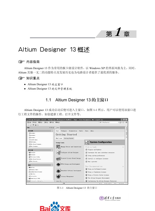
Altium Designer 13概述内容指南 Altium Designer 13作为常用的板卡级设计软件,以Windows XP 的界面风格为主,同时,Altium 其独一无二的功能特点及发展历史也为电路设计者提供了最优质的服务。
知识重点Altium Designer 13的主窗口 Altium Designer 13的文件管理系统1.1 Altium Designer 13的主窗口Altium Designer 13成功启动后便可进入主窗口,如图1-1所示。
用户可以使用该窗口进行工程文件的操作,如创建新工程、打开文件等。
图1-1 Altium Designer 13 的主窗口主窗口类似于Windows 的界面风格,它主要包括6个部分,分别为菜单栏、工具栏、工作窗口、工作面板、状态栏及导航栏。
1.1.1 菜单栏 菜单栏包括用户配置按钮和“文件”、“视图”、“工程”、“窗口”和“帮助”5个菜单按钮。
1.用户配置按钮单击该配置按钮会弹出如图1-2所示的配置菜单,该菜单中包括一些用户配置选项。
(1)“我的账户”命令:用于管理用户授权协议,如设置授权许可的方式和数量。
单击该命令弹出Home 选项卡,如图1-1右侧区域。
(2)“参数选择”命令:用于设置AltiumDesigner 的系统参数,包括资料备份和自动保存设置、字体设置、工程面板的显示、环境参数设置等。
单击该命令将弹出如图1-3所示的“参数选择”对话框。
图1-3 “参数选择”对话框(3)“连接的器件”命令:单击该命令在主界面右侧弹出如图1-4所示的Devices选项卡,图1-2 用户配置菜单。
Altium第三章

中。
找到并选择FD,FD( 触发器)的符号显示在 图中右侧窗口的上方。
点击OK
Copyright © 2009 Altium Limited
7
Altium Designer13.0单页原理图绘制基础 --放置元器件
出现下图所示的放置元器件对话框界面。在该对话框界面中,显
示了FD元件的信息。点击OK按钮,退出该对话框界面。
90度、45度、任意角度和自动连线。
下图给出了45度绘制连线的结果。
Copyright © 2009 Altium Limited
Altium Designer13.0单页原理图绘制基础 --添加信号线连接
按下Shift+Space组合键,切换到90度连线模式下,将U3和U4的 C端按下图进行连接。
Altium Designer13.0单页原理图绘制基础 --放置元器件
继续出现上图放置元器件符号界面,连续点击鼠标四次。当不需
要再放置元件时,按“ESC”键,则退出放置元器件的过程。下
图给出放置完四个FD后的界面。
从图中可以看出,每个元器件上都用U?标识,这是不行的。必须
要对设计中所有的元器件分配一个在该设计中的唯一标号。 AD根据元器件在原理图界面中所处的位置,确定为元器件所分配 的唯一标号。
Ericsson 多频同步系统维护指南说明书

LBI-39090Maintenance Manual SimulcastTransmit SiteRS-232 VersionVolume 1Common EquipmentTable Of ContentsTab Description Publication1Site Grounding...................................LBI-390672Electrostatic Discharge Protection.....LBI-387373Simulcast System Drawings...............LBI-391314Simulcast Cable Drawings.................LBI-388785Transmit Site Cross Connect Panel...LBI-384906MUX Cross Connect.........................AE/LZB 119 1654 7Universal Synchronizer ShelfAssembly...........................................LBI-38476 8Simulcast EDACS® Interface Panel..LBI-391839Cross Connect Interface Panel...........LBI-3918210Power Supplies..................................LBI-3903811Connectorized Jackfields...................ADCP-80-32012WWVB Disciplined Oscillator..........Model 816513Signal Selector...................................Model 8143Ericsson Inc.Private Radio Systems Mountain View Road Lynchburg, Virginia 24502NOTERepairs to this equipment should be made only by an authorized service technician or facility designated by the supplier. Any repairs, alterations or substitution of recommended parts made by the user to this equipment not approved by the manufacturer could void the user’s authority to operate the equipment in addition to the manufacturer’s warranty.NOTICE!The software contained in this device is copyrighted by Ericsson Inc. Unpublished rights are reserved under the copyright laws of the United States.This manual is published by Ericsson Inc., without any warranty. Improvements and changes to this manual necessitated by typographical errors, inaccuracies of current information, or improvements to programs and/or equipment, may be made by Ericsson Inc., at any time and without notice. Such changes will be incorporated into new editions of this manual. No part of this manual may be reproduced or transmitted in any form or by any means, electronic or mechanical, including photocopying and recording, for any purpose, without the express written permission of Ericsson Inc.Copyright© September 1995, Ericsson Inc.LBI-39090Maintenance Manual SimulcastTransmit SiteRS-232 VersionVolume 2EDACS® MASTR® III STATIONTable Of ContentsTab Description Publication 1MASTR III Station Alignment forSimulcast.....................................................LBI-39068 2MASR III Transmitter CombinationManual.........................................................LBI-38775 3800 MHz RF Package..................................LBI-390254EDACS Interface Manual............................LBI-388125Station GETC..............................................LBI-388946AC Outlet Strip............................................LBI-48417Fan, 120 VAC..............................................LBI-48428Power Supply...............................................LBI-385509Power Supply...............................................LBI-38670NOTERepairs to this equipment should be made only by an authorized service technician or facility designated by the supplier. Any repairs, alterations or substitution of recommended parts made by the user to this equipment not approved by the manufacturer could void the user’s authority to operate the equipment in addition to the manufacturer’s warranty.NOTICE!The software contained in this device is copyrighted by Ericsson Inc. Unpublished rights are reserved under the copyright laws of the United States.This manual is published by Ericsson Inc., without any warranty. Improvements and changes to this manual necessitated by typographical errors, inaccuracies of current information, or improvements to programs and/or equipment, may be made by Ericsson Inc., at any time and without notice. Such changes will be incorporated into new editions of this manual. No part of this manual may be reproduced or transmitted in any form or by any means, electronic or mechanical, including photocopying and recording, for any purpose, without the express written permission of Ericsson Inc.Copyright© September 1995, Ericsson Inc.Ericsson Inc.Private Radio SystemsMountain View RoadLynchburg, Virginia 24502LBI-39090Maintenance Manual SimulcastTransmit SiteRS-232 VersionVolume 3Alarm SystemTable Of ContentsTab Description Publication 1Alarm Shelf 19D902821P1 & P2................LBI-384962Test Unit Alarm Interface and ControlChannel Monitor..........................................LBI-38498 3Buffer Board 19C336920G1 EDACSVoter Applications.......................................LBI-39025NOTICE!This manual covers Ericsson and General Electric products manufactured and sold by Ericsson Inc.NOTERepairs to this equipment should be made only by an authorized service technician or facility designated by the supplier. Any repairs, alterations or substitution of recommended parts made by the user to this equipment not approved by the manufacturer could void the user’s authority to operate the equipment in addition to the manufacturer’s warranty.NOTICE!The software contained in this device is copyrighted by Ericsson Inc. Unpublished rights are reserved under the copyright laws of the United States.This manual is published by Ericsson Inc., without any warranty. Improvements and changes to this manual necessitated by typographical errors, inaccuracies of current information, or improvements to programs and/or equipment, may be made by Ericsson Inc., at any time and without notice. Such changes will be incorporated into new editions of this manual. No part of this manual may be reproduced or transmitted in any form or by any means, electronic or mechanical, including photocopying and recording, for any purpose, without the express written permission of Ericsson Inc.Copyright© September 1995, Ericsson Inc.Ericsson Inc.Private Radio SystemsMountain View RoadLynchburg, Virginia 24502。
ADS1213

∑-∆型模数转换器ADS1213简介§1. 芯片结构概述ADS121X 为具有22位高精度的(((A/D 转换器, 它包括一个增益可编程的放大器(PGA )、一个二阶的(((调制器、一个程控的数字滤波器、一个时钟振荡器、一个片内的+2.5V 基准电源、一个串行接口以及一个包括指令寄存器、命令寄存器和校准寄存器的片内微控制器, 对ADS1213还具有4通道的多路转换开关, 其结构框图如图1所示。
A P IN 1A IN 2A P IN 3A P IN 4A NIN 4A N IN 3A IN 2A N IN 1DGND SCLK SDIO SDOUTDV DD图1 ADS12X 芯片内部结构简图ADS12X 具有22位分辨率, 是高精度、大动态范围的(((型A/D 转换器。
其差分输入适合直接与传感器或小电压信号相连。
(((结构用于保证宽动态范围和22位不失真编码。
在10HZ 转换速率时, 用低噪的输入放大器可获得20位的有效分辨率。
在10HZ 转换速率时, 用独特的增强模式可获得16位的有效分辨率。
应用增益可编程的放大器大大增强了转换器动态范围, 增益范围为1, 2, 4, 8, 16。
转换器包括一个灵活的异步串行接口, 该接口是SPI 兼容的。
图中芯片的引脚功能介绍如下:§2. 工作原理输入的数据通过 和 (对ADS1213先进入多路转换开关)进入增益可编程的放大器(PGA ), 由于输入信号为差动输入, 因此必须保证输入端的电压满足共模电压的要求。
芯片内部具有一个偏置电压发生器, 它的工作与否由片内的微控制器控制, 其提供的电压大小为基准电压的1.33倍, 也即电压 。
如基准电压为+2.5V, 那么该偏置电压发生器提供的偏置电压大小为+3.3V,而输入的共模电压范围为 到 , 通过此偏置电压就可以达到使输入信号满足要求。
PGA 中的增益可通过片内寄存器进行设置, 具体可设置的大小为1, 2, 4, 8, 16, 由此增加了转换器的动态输入范围, 简化了与大多数的变送器的接口电路。
AltiumDesignerWinter201313(AD13)软件安装破解版

项目1 Altium Designer 2013 软件认识任务描述本章主要是介绍Altium Designer 2013软件安装方法、软件界面设置方法、软件参数设置方法以及资源定制方法。
通过本章的学习,读者能够完成软件的安装和注册、正确的打开各个工作面板、完成常用的中英文界面切换参数的设置和自动保存时间间隔及保存路径等参数的设置方法、建立新的工具栏,菜单栏及命令的方法。
它将涵盖以下主题:●Altium Designer 2013软件安装●Altium Designer 2013软件界面的设置●Altium Designer 2013软件参数设置●Altium Designer 2013资源定制1.1 Altium Designer 2013 软件1.2 Altium Designer 2013 软件安装1.2.1 硬件环境需求达到最佳性能的推荐系统配置:●Windows 7(32-bit or 64bit)●英特尔®酷睿™ 2双核/四核2.66 GHz或更快的处理器或同等速度的●4G内存●10G硬盘空间(系统安装+用户文件)●双显示器,至少1680x1050 (宽屏)或1600x1200 (4:3 )屏幕分辨率●NVIDIA公司的GeForce ® 8000系列,使用256 MB (或更高)的显卡或同等级别的显卡●USB2.0的端口(如果连接NanoBoard -NB2 or NanoBoard-3000)●DVD 驱动器●Adobe ® Reader ®软件8或以上●连接互联网●IE8浏览器或以上●微软的Excel(产生元器件的材料清单需要)系统最低配置:●Windows XP Professional SP2(或以上)●英特尔® 奔腾™ 1.8 GHz 处理器或同等处理器● 2 G内存● 3.5 GB 硬盘空间(系统安装+ 用户文件)●主显示器的屏幕分辨率至少1280x1024 强烈推荐:次显示器的屏幕分辨率不得低于1024x768●NVIDIA® Geforce® 6000/7000 系列,128 MB 显卡2 或者同等显卡●USB2.0 端口(如果连接NanoBoard-NB2 or NanoBoard-3000)●DVD 驱动器●Adobe® Reader® 8 或更高版本●连接互联网●IE8浏览器或以上●微软的Excel(产生元器件的材料清单需要)已在Windows Vista、Windows XP上完成了最佳系统配置的测试。
Elkay Pacemaker Stainless Steel 19英寸x18英寸x7-1 8英寸单

In keeping with our policy of continuing product improvement, Elkay reserves the right to change product specifications without notice. Please visit for the most current version of Elkay product specification sheets. This specification describes an Elkay product with design, quality, and functional benefits to the user. When making a comparison of other producers’ offerings, be certain these features are not overlooked.
Elkay REV 09102016 PSRQ1918
2222 Camden Court Oak Brook, IL 60523
© 2016 PSRQ1918_spec.pdf
SPECIFICATIONS
OPTIONAL ACCESSORIES
Bottom Grid:
LKWBG1116SS
Drain:
LK99
Faucet:
LKGT1041, LKGT2041
Rinsing Basket:
LKWRB1116SS
Sinkmate:
LKSM17, LKSMHOOK, LKSMSPONGE, LKSMHSL
Soap Dispenser:
LKGT1054
Elkay Pacemaker Stainless Steel 19" x 18" x 7-1/8" Single Bowl Top Mount Sink Model(s) PSRQ1918
维多利亚管道连接器样式31说明书

ALWAYS REFER TO ANY NOTIFICATIONS AT THE END OF THIS DOCUMENT REGARDING PRODUCT INSTALLATION, MAINTENANCE OR SUPPORT.Patented1.0 PRODUCT DESCRIPTIONAvailable Sizes• 3 – 36"/DN80 – DN900Pipe Material• Ductile Iron with a minimum wall thickness of ANSI/AWWA C151/A21.51, Class 53Maximum Working Pressure • Up to 500 psi/3450 kPaFunction• Provides a fully restrained pipe joint to the published maximum allowable working pressure.• Joints are rigid or flexible depending on groove style.• Rigid joints resist axial and angular movement.• Flexible joints allow for restrained axial and angular movement to the couplings published capabilities.2.0 CETIFICATION/LISTINGSCoupling design, materials and testing conform to the requirements of AWWA C606 standard for Grooved and Shouldered Joints.NOTES• Refer to Victaulic publication 10.01 for detailsVictaulic ® Grooved Coupling Style 3123.02System No.Location Submitted ByDateSpec Section Paragraph ApprovedDateHousing: Ductile iron conforming to ASTM A536, Grade 65-45-12. Ductile iron conforming to ASTM A395, Grade 65-45-15, is available upon special request.Housing Coating: (specify choice)Standard: Phenolic Alkyd Primer (2.5 mil).O ptional: Orange enamel.O ptional: Coal tar epoxy coating (3 mils).O rganic zinc primer (3 mils).Bituminous coating.NOTE• Others available, contact Victaulic.Gasket: (specify choice1)G rade “M” FlushSeal™Halogenated Butyl (Brown color code). Temperature range –20°F to +200°F/–29°C to +93°C. Speciallycompounded to conform to ductile pipe surfaces. Recommended for water service within the specifiedtemperature range plus a variety of dilute acids, oil-free air, and many chemical services. UL classified inaccordance with ANSI/NSF 61 for cold +86° F/+30°C potable water service. NOT RECOMMENDED FORPETROLEUM SERVICES.G rade “S” FlushSeal™Nitrile (Red color code). Temperature range –20°F to +180°F/–29°C to + 82°C. Specifically compounded to conform to ductile pipe surfaces. Recommended for petroleum products, air with oil vapors, vegetable and mineral oils within the specified temperature range; except hot air over +140° F/+60° C and water over+150° F/+66°C. NOT RECOMMENDED FOR HOT WATER SERVICES.1S ervices listed are General Service Guidelines only. It should be noted that there are services for which these gaskets are not compatible. Reference should always be made to the latest Victaulic Seal Selection Guide for specific gasket service guidelines and for a listing of services which are not compatible. Bolts/Nuts: (specify choice)S tandard: Carbon steel oval neck track bolts meeting the mechanical property requirements of ASTM A449 (imperial) and ISO 898-1 Class 9.8 (M10-M16) Class 8.8 (M20 and greater). Carbon steel hex nuts meeting the physical and chemical requirements of ASTM A563 Grade B (imperial - heavy hex nuts) and ASTM A563M Class9 (metric - hex nuts). Track bolts and hex nuts are zinc electroplated per ASTM B633 ZN/FE5, finish Type III(imperial) or Type II (metric).O ptional: Stainless steel oval neck track bolts meeting the requirements of ASTM F593, Group 2 (316 stainless steel), condition CW. Stainless steel heavy hex nuts meeting the requirements of ASTM F594, Group 2 (316 stainless steel), condition CW, with galling-resistant coating.22Optional bolts/nuts are available in imperial size only.Exaggerated for ClarityStyle 313 – 12" Sizes14 – 20" Sizes24 – 36" Sizes3Contact Victaulic for details.NOTES• WARNING: Depressurize and drain the piping system before attempting to install, remove, or adjust any Victaulic piping products.• WARNING: FOR ONE TIME FIELD TEST ONLY, the Maximum Joint Working Pressure may be increased to 1 ½ times the figures shown.Style 314A llowable Pipe End Separation and Deflection figures show the maximum nominal range of movement available at each joint for pipe prepared to flexible cut grooved specifications. Pipe cut grooved to rigid cut grooved specifications does not permit expansion and contraction.5W orking Pressure and End Load are total, from all internal and external loads, based on AWWA class 53 or higher ductile iron pipe radius cut grooved in accordance with Victaulic published radius cut groove dimensions.NOTE• WARNING: FOR ONE TIME FIELD TEST ONLY, the Maximum Joint Working Pressure may be increased to 1 ½ times the figures shown.User Responsibility for Product Selection and SuitabilityNoteEach user bears final responsibility for making a determination as to the suitability of This product shall be manufactured by Victaulic or to Victaulic specifications. All products Victaulic products for a particular end-use application, in accordance with industry to be installed in accordance with current Victaulic installation/assembly instructions. standards and project specifications, as well as Victaulic performance, maintenance, Victaulic reserves the right to change product specifications, designs and standard safety, and warning instructions. Nothing in this or any other document, nor any verbal equipment without notice and without incurring obligations.recommendation, advice, or opinion from any Victaulic employee, shall be deemed to Installationalter, vary, supersede, or waive any provision of Victaulic Company's standard conditions Reference should always be made to the Victaulic installation handbook or installation of sale, installation guide, or this disclaimer.instructions of the product you are installing. Handbooks are included with each shipment Intellectual Property Rightsof Victaulic products, providing complete installation and assembly data, and are available No statement contained herein concerning a possible or suggested use of any material, in PDF format on our website at .product, service, or design is intended, or should be constructed, to grant any license Warrantyunder any patent or other intellectual property right of Victaulic or any of its subsidiaries Refer to the Warranty section of the current Price List or contact Victaulic for details.or affiliates covering such use or design, or as a recommendation for the use of suchmaterial, product, service, or design in the infringement of any patent or other intellectual Trademarksproperty right. The terms “Patented” or “Patent Pending” refer to design or utility patents Victaulic and all other Victaulic marks are the trademarks or registered trademarks of or patent applications for articles and/or methods of use in the United States and/or other Victaulic Company, and/or its affiliated entities, in the U.S. and/or other countries.countries.7.0 REFERENCE MATERIALS23.01: AWWA Ductile Iron Pipe - Grooved System 23.05: AWWA (Cast) Fittings25.05: Radius Cut Groove Specifications 29.01: Terms and Conditions/Warranty I-300: Field Installation HandbookI-ENDCAP: Victaulic® End Caps Installation Instructions。
admechanical 13层定义

admechanical 13层定义下载温馨提示:该文档是我店铺精心编制而成,希望大家下载以后,能够帮助大家解决实际的问题。
文档下载后可定制随意修改,请根据实际需要进行相应的调整和使用,谢谢!并且,本店铺为大家提供各种各样类型的实用资料,如教育随笔、日记赏析、句子摘抄、古诗大全、经典美文、话题作文、工作总结、词语解析、文案摘录、其他资料等等,如想了解不同资料格式和写法,敬请关注!Download tips: This document is carefully compiled by the editor. I hope that after you download them, they can help you solve practical problems. The document can be customized and modified after downloading, please adjust and use it according to actual needs, thank you!In addition, our shop provides you with various types of practical materials, such as educational essays, diary appreciation, sentence excerpts, ancient poems, classic articles, topic composition, work summary, word parsing, copy excerpts, other materials and so on, want to know different data formats and writing methods, please pay attention!ADMechanical 13层是一个值得深入研究的概念,它不仅在机械工程领域有着广泛的应用,同时也在现代科技发展中扮演着重要角色。
vivado 2013 密钥

Vivado 2013是Xilinx公司推出的一款高端设计工具,广泛用于FPGA芯片的设计与开发。
在使用Vivado 2013进行开发的过程中,往往需要使用密钥来进行相应的身份验证,以确保软件的合法使用。
下面将就Vivado 2013密钥的获取和使用进行介绍,以帮助大家更好地使用这一款强大的设计工具。
一、Vivado 2013密钥获取渠道在获取Vivado 2013密钥时,主要有以下几种渠道可供选择:1. 官方渠道:用户可以直接从Xilinx官方全球信息湾上获取Vivado 2013的密钥信息,通过注册账号并填写相应的资料,便可获得相关的密钥信息。
2. 第三方渠道:一些第三方的软件供应商或代理商也提供Vivado 2013密钥的获取服务,用户可以通过购买相应的授权码或密钥文件来获取相应的授权信息。
二、Vivado 2013密钥使用方法获取到Vivado 2013的密钥之后,接下来就是需要将密钥应用到软件中,以完成相应的授权。
在使用Vivado 2013密钥时,主要需要按照以下步骤进行操作:1. 打开Vivado 2013软件,选择“帮助”-“许可管理”选项,进入许可管理界面。
2. 在许可管理界面中,选择“添加许可”选项,将获取到的密钥信息填入相应的字段中,并保存设置。
3. 确认密钥信息已经成功添加,并重新启动Vivado 2013软件,使许可信息生效。
三、注意事项在获取和使用Vivado 2013密钥的过程中,需要注意以下几个方面的问题:1. 合法性:在获取Vivado 2013密钥时,应当选择正规渠道获取,以确保相关的许可信息的合法性。
2. 权限:在使用Vivado 2013密钥时,需要确保自己拥有相应的授权,否则将无法完成正常的软件授权和使用。
3. 更新:Vivado 2013的密钥信息可能会在一段时间后失效,因此需要定期关注官方全球信息湾或者第三方渠道,获取最新的密钥信息以保证软件的正常使用。
经典综合过程Design Compiler

用Design Analyzer设置特征参数: 在读入设计后,要说明设计的环境变量,这些环境变量包括了当信号到达端口(port)时, 他们的的驱动能力,或者输出端口的负载能力。 本节就是描述如何来设置闹钟设计的这些参数。 为TOP模块设置参数 设置参数时可以使用Symbol view。 1.选择TOP. 2. 单击向下的箭头。 3. 点击Symbol View 按钮。 设置输入端口的驱动能力 假设除了CLK的所有输入端口的驱动能力为0.08(单位由目标库决定)。你可以同时选定并设 定所有的要设定的输入端口。 1.使用鼠标左键来选择输入端口ALARM; 2.使用中间选择其他的除了CLK之外的所有的输入端口,见Figure 7-17。
2. 选择Library中的 WORK. 3. 选择Re-Analyze Out-Of-Date Libraries 4. 选择Design list中ALARM_COUNTER(BEHAVIOR). 5. 点击OK.
在Design Analyzer窗口中,出现ALARM_COUNTER的elaborated后的图标。
3. 选择synopsys.vhd. 4. 点击OK. 出现VHDL 的窗口window并且显示行为。 5. 当Design Analyzer提示符(design_analyzer>) 出现, 在VHDL窗口中单击 Cancel。
读入最底层的设计模块 为了保证对所有模块的调用可以被正确的解析,我们要从设计的最底层模块开始读入,最 后读入最上层的模块。 tutorial中最底层模块包括: ALARM_COUNTER ALARM_STATE_MACHINE CONVERTOR (2) HOURS_FILTER TIME_COUNTER TIME_STATE_MACHINE 使用read命令读入CONVERTOR因为它是PLA格式。.
- 1、下载文档前请自行甄别文档内容的完整性,平台不提供额外的编辑、内容补充、找答案等附加服务。
- 2、"仅部分预览"的文档,不可在线预览部分如存在完整性等问题,可反馈申请退款(可完整预览的文档不适用该条件!)。
- 3、如文档侵犯您的权益,请联系客服反馈,我们会尽快为您处理(人工客服工作时间:9:00-18:30)。
Confidential
Page2
ADY13 Electrical Design Specification
1.1 Power requirement
+CPU_CORE
TABLE OF CONTENTS
ADY13 Electrical Design Specification
ADY13 Electrical Design Specification
By: Henry Huang HW1 Department
Confidential
Page1
ADY13 Electrical Design Specification
+1.2VP $% +1.25V +2.5V +1.5VS ) +1.8VALW +3VALW +5VALW +12VALW
!"# &'&"# &'&"# &&(
*1: Always on when AC exist, no AC exist, contro by EC_ON
39: 39: 9:
39: ,%- . . 39: 4 801
-,4 8,%- . . &%$/01.2345*23 7
Confidential
Page3
ADY13 Electrical Design Specification 1.3
Item 1 2 3 4 5 6 7 8 9 10 11 12 13 14 15 16 17 18 19 20 21 22 23 24 25 26 27 28 29 30 31 32
Power/EE Interface definition
Pin Name +CPU_CORE +1.2VP +1.25V +2.5V +1.5VS +1.8VALW +3VALW +5VALW +12VALW B+ VL CHGRTC SDREF SYSON SUSP# ACIN ACOFF FSTCHG IREF AIR_ADP# BATT-OVP 6C/8C#/4C# BATT_TEMP SMB_EC_CK1 SMB_EC_DA1 PM_GMUXSEL PM_STPCPU# CPU_VID[0..4] PM_DPRSLPVR VR_ON VGATE SHDN# Type *1 Power Power Power Power Power Power Power Power Power Power Power Power Reference Voltage Input Input Output Input Input Output Output Output Output Output Input I/O Input Input Input Input Input Output Input CPU core power +1.2V power +1.25V power +2.5V power +1.5V power +1.8V power +3.3V power +5V power +12V power System power +5V Linear power RTC Charger power DDR Memory reference voltage (1.25V), need provide min. 10mA. Enable S5 off power Enable S3 off power Inform to EC and System, AC exist or not. EC output to battery charger, use battery power or AC power. EC select charger mode EC control charger current. Inform to EC and Battery, limit charger current because airplane. Inform to EC, do battery protection. Inform to EC, 6 cell, 8cell or 4cell battery to use. Inform to EC, Battery temperature EC SMBus CLK EC SMBus Data Intel Speedstep support. Intel C3 support Intel CPU VID input Intel C4 support Enable +CPU_CORE and +1.2VP +CPU_CORE power good output. Shut down +3VALW, +5VALW and +12VALW. (all power will shut down because EC no power) Function Description Note
*1 Type defined for power section.
Confidential
Page4
ADY13 Electrical Design Specification 1.4 Power on sequence
Confidential
Page5
ADY13 Electrical Design Specification%#
Confidential
Page6
ADY13 Electrical Design Specification ♦ Time table
T1 T2 T3 T4 T5 T6 T7 T8 T9 T10 T11 T12 & ,%- . . /-%)$/01.*%2345*%)23* ,%- . . /-%)$/01.*%2345*%623) ,%- . . /-%)$/01.*%2345*%623) ,%- . . /-%)$/01.*%2345*%623) 7
2 &'&"# 4
0+ &&(4
0+ 0
♦ Reference document list
7/#"
. 30 /-%) &% ;$" ,.5<,=7> 4 01 &
+1.525V *+
1.2
Power Supply Figure
2 &'&"# 4
0+ &&(4
0+ 0 ,%- . . /-%)$/01.*%2345*%623) 4 801 /-%)$/01.*%2 345*%)2 3*5 $ 3* ,%- . . /-%)$/01.*%2345*%)23** /-%)$/01.*%2345*%)23*) &%$/01.2345*23*
