TEW5613中文资料
英飞拓光端机
独立式
插卡式
3729 系列光端机兼容 9/125 微米单模光纤
接在摄像机端的发射机 3729TA 同接在监视器端的接收机 3729RA 配套使用
附件(可选) 3910-000 3932 3951 3952 3954
19 英寸 1U 散热风扇 一路数据加一路视频防雷保护卡 光纤传输中继器 开关信号采集器 控制码分配器
独立式光端机电源配置 将 3729 插卡式光端机安装到 1 个单槽机箱 3910-1S 时,则变成独立式光端机。
此时,该光端机可以由 1 个 12VDC@1A 插入式直流电源(3921-12D-1,110V; 3921-12D-2,230V)供电。将导线插入到光端机电源连接座内,用螺丝刀将导线锁紧, 见下图。
注意事项
本产品应由专业的技术人员进行安装。非专业人员请勿擅自安装操作。安装操 作请联系专业人员。
在该产品的安装过程中,如果你需要相关信息或服务,请联系当地供应商,或 者请拨打 INFINOVA 客户服务专线:1-732-355-9100,51 Stouts Lane, Monmouth Junction, NJ 08852 U.S.A. 注意,在返送任何产品进行维修前,请务必索取返修授权 号码和装运说明书。
图 4. 菊花链接 注意:
请在最后一个接收机处接上 120 欧姆终端电阻来抑制信号反射。 8
浪涌保护
浪涌保护电路用于保护 Infinova 光端机免受瞬时浪涌和过载电压的破坏。交流 电源或闪电产生的感应电流都可能引发电压过载,并传导到数据线,进而损坏光端 机内部芯片,造成光端机工作不正常甚至失效。良好的接地装置能保证光端机内部 过压保护电路功能正常实现。为增强保护效果,我们建议用户采用 3932 来保护光端 机设备不受浪涌和过载电压的危害。下图为采用了 3932 防雷保护卡后,光端机的一 个工作示意图:
GPON产品简介

最大宽窄线数
128路ADSL2+;
64路VDSL2;
256路POTS
四、MA5620/MA5626设备
1.1硬件结构
2.2单板
MA5612单板分为主控板、业务板、电源板和风扇控制板。
\
2.3设备配置
三、MA5616设备:
1.1硬件结构
MA5616支持6个槽位:
0槽位配置主控板;
1~4槽位为业务板槽位;
5槽位配置电源板。
2.2单板
MA5616单板分为主控板、业务板、电源板和风扇控制板。
\
2.3设备配置
GPON产品—OLT
一、ቤተ መጻሕፍቲ ባይዱA5680T设备:
GPON产品—ONU
一、MA5610设备:
1.1硬件结构
MA5610支持6个槽位:
0槽位配置主控板;
1~4槽位为业务板槽位;
5槽位配置电源板。
2.2单板
MA5610单板分为主控板、业务板、电源板和风扇控制板。
\
2.3设备配置
MA5610设备接入用户线的配置如下:
MA5616设备接入用户线的配置如下:
产品
MA5616(支持AC/DC输入)
工作温度
-25℃~ + 65℃;-40℃~ + 65℃(带加热板)
单板交换容量
(800M+2.5G)bit/s
上行接口
1*GPON/1*EPON+GE/ 2GE
业务插槽
4
业务板
32路ADSL2+(内置SPL);
16路VDSL2(内置SPL,8a~30a);
产品
MA5610(支持AC/DC输入)
产品资料

1、TOPwe AuteX5612智能无线控制器TOPwe AuteX5612是一款万兆级无线控制器,提供1个万兆接口扩展能力及12个固定千兆以太口和4个COMBO接口。
基于业界领先的智能分布式WLAN交换架构研制开发的AuteX5612无线控制器具有强大灵活的无线用户接入及Fit AP管理能力。
整机提供256台Fit AP及8192个无线用户的管理能力。
并提供无缝漫游、用户安全接入、WIDS、基于用户角色的自动策略控制、无线信道动态控制、射频功率自动调整、无线用户自动负载分担等多种应用及控制手段。
高效灵活的产品设计AuteX5612无线控制器提供10M到10G的多种速率端口支持,并提供RJ45、COMBO 等多种类型端口支持,极大适应各种现有网络的接入环境。
AuteX5612根据用户网络需求可采取串接或旁挂方式部署,最大限度减少无线网络部署对用户原有网络环境的改动,从而有效减少无线网络部署的时间和成本。
易于部署和管理基于先进的集中智能管控技术设计理念,AuteX5612可对其管控的FIT AP(即使AP 位于远程分支机构,并通过Internet相连)提供自动软件升级、自动配置下发和基于中心的管理特性。
这极大减少了设备部署及维护的成本和难度,并向用户提供即插即用的WLAN解决方案。
另外,AuteX5612内置极具人性化的中英文WEB配置界面,帮助网络管理员以最高的效率完成设备的配置和维护工作。
硬件支持802.11n演进基于业界领先的智能分布式WLAN交换特性,AuteX5612可灵活决策无线用户数据的本地转发或集中转发,为网络中的WLAN数据提供基于硬件级别的优化转发流程,并可有效避免由完全集中式WLAN交换架构所带来的控制器性能瓶颈问题。
从而为全802.11n网络部署提供了最切实可行的解决方案。
强大的RF部署工具强大的RF部署工具将为用户提供最具时间效益的可视化无线网络部署和规划手段。
通过向RF部署工具导入需要实施WLAN部署的建筑物各楼层平面图及其面积、预期的覆盖效果、阻碍物的材质等参数,RF部署工具将综合考虑整个覆盖区域内三维空间的射频特性,自动输出各楼层AP的最佳部署位置及预测的覆盖效果。
数字化电能表表光纤接口使用说明书样本
1 概述DTSD341/DSSD331(配置号为ME2(SN))三相电子式多功效电能表是一款符合DL/T 614《多功效电能表》标准0.2S 级和0.5S 级三相电子式多功效电能表。
其关键特点为计量信号为数字流输入、高速数据处理能力、电源采取双路外接电源供电。
适适用于采取IEC61850-9-1/2标准协议电能计量体系。
DTSD341/DSSD331(配置号为ME2(SN))三相电子式多功效电能表研发和生产符合以下标准: GB/T 15543《电能质量 三相电压许可不平衡度》 GB/T 17882《2级和3级静止式交流无功电能表》 GB/T 17883《0.2S 级和0.5S 级静止式交流有功电能表》 DL/T 614 《多功效电能表》DL/T 645 《多功效电能表通信规约》(威胜企业对此协议有扩展) IEC61850-9-2 《数字化变电站通信规约》 1.1 工作原理DSSD331/DTSD341(配置号为ME2(SN))三相电子式多功效电能表是一款遵照IEC61850-9-2LE (数字化变电站内通信规约)协议全新数字接口式多功效电能表,采取当今世界流行高级电能表设计方案:数字信号处理器和中央微处理器相结合构架,将数字信号处理器高速数据吞吐能力和中央微处理器 复杂管理能力完美结合。
经过协议处理芯片获取合并单元数据协议包,传送至数字信号处理单元完成对电参量测量,电能累计和电能计算等任务,后和中央微处理器进行数据交换,由中央微处理器最终完成表计显示,数据统计,储存,人机交互,数据交换等复杂管理功效。
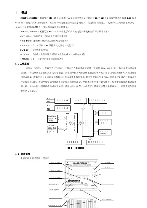
其整表硬件原理框图图1所表示。
工工工工-1 工工工工-2工工工工工工10/100MBase-TX(RJ45)100M Base-FX(MIC/1300nm 工工工工工工工工工工工工工工工工工工工工 工工工工/工工工工工工工工工工工 工工工工工工工工工工工工RS485/工工工工工工工工工工2工工工工工工工L1N1L2N2图 1 原理框图1.2 面板说明电表面板说明详见图2所表示。
TPS54231中文资料

FEATURES
1
•2 3.5V to 28V Input Voltage Range • Adjustable Output Voltage Down to 0.8V • Integrated 80 mΩ High Side MOSFET Supports
2
PRODUCTION DATA information is current as of publication date. Products conform to specifications per the terms of the Texas Instruments standard warranty. Production processing does not necessarily include testing of all parameters.
These devices have limited built-in ESD protection. The leads should be shorted together or the device placed in conductive foam during storage or handling to prevent electrostatic damage to the MOS gates.
ABSOLUTE MAXIMUM RATINGS(1)
over operating free-air temperature range (unless otherwise noted)
VIN
ENInput VolFra bibliotekageBOOT VSENSE
烽火光模块及光猫

OL100CR-22C 独立型单纤光纤收发器,发射波长1550nm,接收1310nm,可被FR系列管理,单模,10/100M,40km,SC/PC,220V
OL200FR-04A 模块型网管光纤收发器,可管理CR系列,多模,10/100/1000M,550m,SC/PC
OL200FR-04B 模块型网管光纤收发器,可管理CR系列,单模,10/100/1000M,20km,SC/PC
OL200FR-04C 模块型网管光纤收发器,可管理CR系列,单模,10/100/1000M,40km,SC/PC
OL200FR-22D 模块型单纤网管光纤收发器,发射波长1550nm,接收1310nm,可管理CR系列,单模,10/100M,60km,SC/PC
OL200FR-22E 模块型单纤网管光纤收发器,发射波长1550nm,接收1310nm,可管理CR系列,单模,10/100M,80km,SC/PC
OL100C-02E 独立型光纤收发器,单模,10/100M,120km,SC/PC,220V
10/100Mbps自适应单纤光纤收发器
OL200F-22B 模块型单纤光纤收发器,发射波长1550nm,接收1310nm,单模,10/100M,20km,SC/PC
OL200F-22C 模块型单纤光纤收发器,发射波长1550nm,接收1310nm,单模,10/100M,40km,SC/PC
OL200FR-02C 模块型网管光纤收发器,可管理CR系列,单模,10/100M,40km,SC/PC
OL200FR-02D 模块型网管光纤收发器,可管理CR系列,单模,10/100M,60km,SC/PC
德特威勒产品手册可编辑
DMD
内模板
外模板
模板
(5-8um半径)
(0-23um半径)
1
0.33ps/m
0.33ps/m
2
0.27ps/m
0.35ps/m
3
0.26ps/m
1300nm
台阶(双向平均值)
≤0.10
dB
不均匀性(整个光纤长度)和衰减点不连续性
≤0.10
dB
背向散射衰减系数差异(双向测试)
≤0.10
dB/km
几何特性
芯径
62.5±2.5
um
包层直径
125.0±1.0
um
包层不圆度
≤1.0
%
涂层直径
242±7
um
涂层/包层同心度误差
≤12.0
um
涂层不圆度
≤6.0
unilanR MPS六类屏蔽配线架框架47
unilanR MS六类屏蔽配线架框架47
unilanR六A类屏蔽线缆48R六A类屏蔽配线架50
unilanR七类屏蔽线缆51
unilanR七A类屏蔽线缆54
unilanR GG-45系列7类模块55
Unipatch PS系列7A类模块56
%
芯/包层同心度误差
≤1.5
um
Unilan?万兆光纤特性
Unilan?德特威勒万兆多模光纤特性:
满足IEC60793-2-10A1b、IEEE802.3ae、Bellcore、EIA/TIA-492AAAC、ISO11801OM3、TIA/EIA-455和TIA568C.3-2009标准,在850nm处可以支持万兆以太网速率达300米及支持1000Base-SX达900米距离,同时又可向下兼容目前的1G,100Mbps,10Mbps以太网应用。
AD561芯片介绍与应用中英文对照外文翻译文献

中英文对照外文翻译附件1:外文翻译译文AD561芯片的介绍与应用AD561是一款集成了10位数模转换器和高稳定电压转换器的芯片。
使用10个高精密电流控制开关,控制放大器,引用电压和激光微调薄膜硅铬电阻网络,该设备生产一种快速、精确的模拟输出电流。
激光微调电阻器的应用快速而准确,稳定的电流到电压的转换,它们的精度可以达到0.1%。
从而在许多情况下消除外部剪切。
几个主要技术结合起来,使AD561提供最精确和最稳定的10位DAC。
低温度系数,高稳定性的薄膜网络在晶圆级微调高分辨率激光系统0.01%的典型的线性关系。
【AD561产品说明】AD561 还包含一个低噪音、高稳定性的稳压二极管生产参考电压与较好的长期稳定性和挑战最离散稳压引用的温度周期特点。
允许自定义的每个设备的温度系数校正激光裁剪温度补偿电路。
这将导致 15 ppm/°C / ° C ;一个典型的全面温度系数TC 是测试和保证 30 ppm / ° C 最大值为 K 和 T 版本、 60 ppm/°C / ° C 最大 S,和 80 ppm / ° C 。
该AD561可在四个性能等级。
该AD561J和K,并指明了在0 ° C至+70 ° C 使用温度范围,并在一个16引脚密封陶瓷拨用或16引脚塑料DIP成型。
和T级的AD561S指定为-55 ° C至+125 ° C范围内,并在陶瓷封装。
【特征】功能框图总电流输出转换器高稳定性掩埋稳压二极管参考激光修整,精度高(1 / 4 LSB最大错误,AD561K,T)边输出为0 V至+10 V的应用电阻器,65 V输入快速设置- 250毫微秒到1 / 2 LSB保证在整个工作的单调性温度范围TTL/晶体管逻辑和CMOS兼容(正真逻辑)单芯片单片建设可用于片式结构兼容信息产业部- STD - 883标准。
TLV5616芯片资料
–2–3.502567681280153617922304–10.522816332835841.510–0.5–1.5–2.5–3Digital Code51510242048256030723840Figure 132565127681536204823040.1Digital CodeDIFFERENTIAL NONLINEARITY ERROR0.325603328358438400.250.20.150.050–0.05–0.1–0.15–0.2–0.25–0.3–0.35–0.4–0.45–0.510241280179228163072Figure 14IMPORTANT NOTICETexas Instruments and its subsidiaries (TI) reserve the right to make changes to their products or to discontinue any product or service without notice, and advise customers to obtain the latest version of relevant information to verify, before placing orders, that information being relied on is current and complete. All products are sold subject to the terms and conditions of sale supplied at the time of order acknowledgement, including those pertaining to warranty, patent infringement, and limitation of liability.TI warrants performance of its semiconductor products to the specifications applicable at the time of sale in accordance with TI’s standard warranty. Testing and other quality control techniques are utilized to the extent TI deems necessary to support this warranty. Specific testing of all parameters of each device is not necessarily performed, except those mandated by government requirements.CERTAIN APPLICATIONS USING SEMICONDUCTOR PRODUCTS MAY INVOLVE POTENTIAL RISKS OF DEATH, PERSONAL INJURY, OR SEVERE PROPERTY OR ENVIRONMENTAL DAMAGE (“CRITICAL APPLICATIONS”). TI SEMICONDUCTOR PRODUCTS ARE NOT DESIGNED, AUTHORIZED, OR WARRANTED TO BE SUITABLE FOR USE IN LIFE-SUPPORT DEVICES OR SYSTEMS OR OTHER CRITICAL APPLICATIONS. INCLUSION OF TI PRODUCTS IN SUCH APPLICATIONS IS UNDERSTOOD TO BE FULLY AT THE CUSTOMER’S RISK.In order to minimize risks associated with the customer’s applications, adequate design and operating safeguards must be provided by the customer to minimize inherent or procedural hazards.TI assumes no liability for applications assistance or customer product design. TI does not warrant or represent that any license, either express or implied, is granted under any patent right, copyright, mask work right, or other intellectual property right of TI covering or relating to any combination, machine, or process in which such semiconductor products or services might be or are used. TI’s publication of information regarding any third party’s products or services does not constitute TI’s approval, warranty or endorsement thereof.Copyright © 1999, Texas Instruments Incorporated。
锡兰光纤产品及配件说明书

561/562 SeriesULTRAlign™AccessoriesFiber to fiber via GRIN lens consisting of 561D-XYZ-LH,561-FC (2 ea), 561-TS, 561-GR, 561D-XYZ, and 561-TILT Ordering InformationModel (Metric)Description561-FH Bare Fiber Holder for 125 µm Fibers561-FC Fiber Chuck Holder561-RFC Fiber Chuck Rotation Mount561-GM Gimbal Fiber Chuck Positioner561-FCH FC Connectorized Fiber Holder561-SCH SC Connectorized Fiber Holder561-LCH LC Connectorized Fiber Holder561-FCA3SMA Connectorized Fiber Holder with Rotation 561-FCA4FC Connectorized Fiber Holder with Rotation 561-FCA6ST Connectorized Fiber Holder with Rotation 561-MM Module Mount561-V1V-Groove Module, 1–1.75 mm561-V2V-Groove Module, 2–2.75 mm561-V3V-Groove Module, 3 & 3.25 mm561-BL1 1 mm Ball Lens Module561-BL2 2 mm Ball Lens Module561-BL3 3 mm Ball Lens Module561-GR Gradient Index (GRIN) Lens Mount561-OBJ Objective Lens Mount561-VH Vacuum Waveguide MountWG-16-DEV Waveguide GripperWG-16-ARRAY Fiber Array Gripper561-UM (M-561-UM)Universal Module561-GBM Blank, GRIN Lens Mount561-OBM Blank, Objective Lens Mount561-UST561 Fixed Platform, Universal Stand561-TS561 Fixed Platform, Narrow Profile T-Stand 562-UST562 Fixed Platform, Universal Stand562-TS562 Fixed Platform, Narrow Profile T-Stand 561-ADPT Adaptor, Raises 561 Stage to 562 HeightBare Fiber Holder•Improved design for 125 µm diameter bare fibers •Fiber gently held in precision V-grooveBare fiber holder—561-FHFiber Chuck Holder•Designed to hold 0.25 in. (6.35mm) diameter fiber chucks •Mounts all Newport fiber chucks (see pages 236 and 1061)Fiber chuck holder—561-FCFiber Chuck Rotation Mount•Designed to hold 0.25 in. (6.35 mm) diameter fiber chucks •Rotation of 360°in θx , Sensitivity of 2°Fiber chuck rotation mount—561-RFCGimbal Fiber Chuck Positioner•Designed to hold 0.25 in. (6.35 mm) diameter fiber chucks •Rotation of 360°in θx , Tilt of ±5°in θY θZ •Sensitivity of 2°in θx , ±12 arc sec in θY θZGimbal fiber chuck positioner—561-GMConnectorized Fiber Holders•Mounts FC, SC, or LC connectorized fibersConnectorized fiber holder 561-FCH (for FC connector)561-SCH (for SC connector)561-LCH (for LC connector)Connectorized Fiber Holders with Rotation•Mounts SMA, FC, or ST connectorized fibers •Fiber can be rotated 360°in holderConnectorized fiber holder with rotation561-FCA3 (for SMA connector)561-FCA4 (for FC connector)561-FCA6 (for ST connector)Gradient Index (GRIN) Lens MountGradient index (GRIN)lens mount—561-GR•Mounts GRIN lenses up to 4.5 mm diameter•Lenses held in a V-groove with a nylon-tipped setscrewV-Groove Modules•Modules for holding 1 to 3.25 mm diameter cylindrical devices •Ideal for GRIN lenses, fiber collimators, and fiber ferrules•Gently held in 561-MM Module MountV-Groove Modules—561-V1, 561-V2,and 561-V3Ball Lens Modules•Modules for holding 1, 2, or 3 mm diameter ball lenses •Gently held in 561-MM Module MountBall Lens Modules—561-BL1, 561-BL2,and 561-BL3Objective Lens Mount•Mounts microscope and laser diode objective lenses •Standard 0.800-36 RMS threadObjective lens mount—561-OBJVacuum Waveguide Mount•One to eight vacuum ports can be used to mount small to large devices •Requires a user supplied vacuum pumpVacuum waveguide mount—561-VHBlank Mounts•Machine to create custom component holders to mount on 561/562 railBlank, GRIN lens mount—561-GBMBlank, objective lens mount—561-OBMModule Mount•Accepts modules for holding ball lenses, GRIN lenses,fiber collimators, and fiber ferrules •Optics and devices are gently held in modulesModule Mount—561-MMUniversal Module•Use to mount custom component holders on the 561/562 railUniversal module—561-UM 561 to 562 Height Adaptor•Raises 561 stages to 562 stage height •For use with 561-XYZ and 561-YZ561 to 562 Height adaptor—561-ADPTWaveguide Gripper•Firm, reproducible mounting for a wide range of planar device sizes •Precision polished surfaces with kinematic gripping action •Spring loaded with lock-open feature for one-handed loading •25 mm wideFiber Array Gripper•Firm, reproducible mounting for 1- to 16-channel fiber arrays or shorter planar devices •Precision polished surfaces with kinematic gripping action •Spring loaded with lock-open feature for one-handed loading•12 mm wideWaveguide/Fiber Array Grippers—WG-16-DEV WG-16-ARRAYUniversal Stand•Fixed platform to mount a component next to a positioning stageUniversal stand—561-USTUniversal stand—562-USTT-Stand•Fixed platform to mount a component between two positioning stagesT-stand—561-TST-stand—562-TSO P T I C A L F I B E R S & A C C E S S O R I E SF I B E R O P T I C C O M P O N E N T SL A S E R SF I B E R A L IG N M E N T & A S S E M B L YP O W E R M E T E R S & D E T E C T O R SF I B E R O P T I C ST E S T I N S T R U M E N T A T I O NL A S E R D I O D E T E S TI N GModel 561-FH8-32 SET SCREWModel 561-FCFIBER CHUCK Model 561-RFCModel 561-GMModel 561-FCHModel 561-LCH8-32 SET SCREWLASER DIODE TESTINGFIBER OPTICS TEST INSTRUMENTATIONPOWER METERS & DETECTORSFIBER ALIGNMENT & ASSEMBLYLASERSFIBER OPTIC COMPONENTSOPTICAL FIBERS & ACCESSORIESModel 561-SCH 8-32 SET SCREWModel 561-FCA SeriesLOCKINGModel 561-MMLOCATION FOR ALL MODULES(14.5)Model 561-V1Model 561-V2Model 561-V3561-V3O P T I C A L F I B E R S & A C C E S S O R I E SF I B E RO P T I C C O M P O N E N T SL A S E R SF I B E R A L IG N ME N T & A S S E M B LYP O W E RM E T E R S & D E T E C T O R SF IB E R O P T IC S T E ST I N S T R U M E N T A T I ONL A S E R D I O D E T E S T I N GModel 561-BL1Model 561-BL2Model 561-BL3Model 561-GRModel 561-OBJModel 561-VHModel WG-16-DEV, WG-16-ARRAYSliding Jaw2000.51.01.52.02.53.03.54.046810121416H (m m )W (mm)The WG-series grippers can handle components with any height/width dimension combination that fits within the shaded area.Dimension (mm)ModelL WG-16-DEV 25WG-16-ARRAY12LASER DIODE TESTINGFIBER OPTICS TEST INSTRUMENTATIONPOWER METERS & DETECTORSFIBER ALIGNMENT & ASSEMBLYLASERSFIBER OPTIC COMPONENTSOPTICAL FIBERS & ACCESSORIESModel 561-UM.125ThreadDimension [in. (mm)]Model (Metric)A B C D 561-UM (M-561-UM)4-40 (M3)8-32 (M4)1.000(25.0)0.125 (3.4)Model 561-GBMModel 561-OBMModel 561-TSModel 561-UST.29 (7.4) CLRøModel 562-UST.36 (9.04)Model 562-TSModel 561-ADPT4X .125 THRU。
5833中文资料

5833中⽂资料Designed to reduce logic supply current, chip size, and system cost, the UCN5833A/EP integrated circuits offer high-speed operation for thermal printers. These devices can also be used to drive multi-plexed LED displays or incandescent lamps within their 125 mA peak output current rating. The combination of bipolar and MOS technolo-gies gives BiMOS II smart power ICs an interface flexibility beyond the reach of standard buffers and power driver circuits.These 32-bit drivers have bipolar open-collector npn Darlington outputs, a CMOS data latch for each of the drivers, a 32-bit CMOS shift register, and CMOS control circuitry. The high-speed CMOS shift registers and latches allow operation with most microprocessor-based systems at data input rates above 3.3 MHz. Use of these drivers with TTL may require input pull-up resistors to ensure an input logic high.The UCN5833A is supplied in a 40-pin dual in-line plastic package with 0.600" (15.24 mm) row spacing. At an ambient temperature of +75°C, all outputs of the DlP-packaged device will sustain 50 mA continuously. For high-density applications, the UCN5833EP is available. This 44-lead plastic chip carrier (quad pack) is intended for surface-mounting on solder lands with 0.050" (1.27 mm) centers.CMOS serial data outputs permit cascading for applications requiring additional drive lines.FEATURESI To 3.3 MHz Data Input Rate I 30 V Minimum Output Breakdown I Darlington Current-Sink Outputs I Low-Power CMOS Logic and LatchesBiMOS II 32-BIT SERIAL-INPUT,LATCHED DRIVERAlways order by complete part number:Part Number Package UCN5833A 40-Pin DIP UCN5833EP 44-Lead PLCCData Sheet 26185.16A*58335833BiMOS II 32-BIT SERIAL-INPUT,LATCHED DRIVER115 Northeast Cutoff, Box 15036Worcester, Massachusetts 01615-0036 (508) 853-5000SERIAL DATA IN POWER STROBE OUT OUT OUT OUT OUT OUT 123456OUT7OUT 8OUT 9OUTOUT OUTOUT OUTLOGIC SUPPLY OUT OUT Dwg. No. A-13,051TYPICAL OUTPUT DRIVERSUBOUT115 Northeast Cutoff, Box 15036Worcester, Massachusetts 01615-0036 (508) 853-5000Copyright ? 1986, 1995, Allegro MicroSystems, Inc.5833BiMOS II 32-BIT SERIAL-INPUT,LATCHED DRIVERTRUTH TABLEL = Low Logic Level H = High Logic Level X = Irrelevant P = Present State R = Previous StateELECTRICAL CHARACTERISTICS at T A = +25°C, V DD = 5 V (unless otherwise noted).Limits CharacteristicSymbol Test Conditions Min.Max.Units Output Leakage Current I CEX V OUT = 30 V, T A = 70°C —10µA Collector-Emitter V CE(SAT)l OUT = 50 mA — 1.2V l OUT = 100 mA— 1.7V Input VoltageV IN(1) 3.5 5.3V V IN(0)-0.3+0.8V Input Currentl IN(1)V IN = 5.0 V — 1.0µA l IN(0)V IN = 0 V —-1.0µA Serial Output VoltageV OUT(1)I OUT = -200 µA 4.5—V V OUT(0)I OUT = 200 µA—0.3V Supply Currentl DD One output ON, l OUT = 100 mA — 1.0mA All outputs OFF—50µA Output Rise Time t r l OUT = 100 mA, 10% to 90%—500ns Output Fall Timet fl OUT = 100 mA, 90% to 10%—500nsNOTE: Positive (negative) current is defined as going into (coming out of) the specified device pin.Saturation Voltage5833BiMOS II 32-BIT SERIAL-INPUT,LATCHED DRIVER115 Northeast Cutoff, Box 15036Worcester, Massachusetts 01615-0036 (508) 853-5000TIMING CONDITIONS(V DD = 5.0 V, Logic Levels are V DD and Ground)A.Minimum Data Active Time Before Clock Pulse(Data Set-Up Time)..........................................................................75 ns B.Minimum Data Active Time After Clock Pulse(Data Hold Time).............................................................................75 ns C.Minimum Data Pulse Width ................................................................150 ns D.Minimum Clock Pulse Width...............................................................150 nsE.Minimum Time Between Clock Activation and Strobe.......................300 nsF.Minimum Strobe Pulse Width .............................................................100 nsG.Typical Time Between Strobe Activation andOutput Transition ...........................................................................500 nsDwg. No. A-12,276ASerial Data present at the input is transferred to the shift register on the logic “0” to logic “1” transition of the CLOCK input pulse. On succeeding CLOCK pulses, the registers shift data information towards the SERIAL DATA OUTPUT. The SERIAL DATA must appear at the input prior to the rising edge of the CLOCK input waveform.Information present at any register is transferred to its respective latch when the STROBE is high (serial-to-parallel conversion). The latches will continue to accept new data as long as the STROBE is held high. Applications where the latches are bypassed (STROBE tied high) will require that the OUTPUT ENABLE input be low during serial data entry.When the OUTPUT ENABLE input is low, all of the output buffers are disabled (OFF) without affecting the information stored in the latches or shift register. With the OUTPUT ENABLE input high, the outputs are controlled by the state of the latches.CLOCK DATA INSTROBE NOUTPUT ENABLEOUT5833BiMOS II 32-BIT SERIAL-INPUT,LATCHED DRIVERNOTES:1.Exact body and lead configuration at vendor’s option within limits shown.2.Lead spacing tolerance is non-cumulative.3.Lead thickness is measured at seating plane or below.UCN5833ADimensions in Inches (controlling dimensions)Dimensions in Millimeters (for reference only)123Dwg. MA-003-40 mm20421123Dwg. MA-003-40 in2045833BiMOS II 32-BIT SERIAL-INPUT,LATCHED DRIVER115 Northeast Cutoff, Box 15036Worcester, Massachusetts 01615-0036 (508) 853-5000UCN5833EPDimensions in Inches (controlling dimensions)Dimensions in Millimeters (for reference only)Dwg. MA-005-44A mm0.53340Dwg. MA-005-44A in0.021740NOTES:1.Exact body and lead configuration at vendor’s option within limits shown.2.Lead spacing tolerance is non-cumulative.5833BiMOS II 32-BITSERIAL-INPUT,LATCHED DRIVERThe products described here are manufactured under one or more U.S. patents or U.S. patents pending.Allegro MicroSystems, Inc. reserves the right to make, from time to time, such departures from the detail specifications as may be required to permit improvements in the performance, reliability, or manufacturability of its products. Before placing an order, the user is cautioned to verify that the information being relied upon is current.Allegro products are not authorized for use as critical components in life-support devices or systems without express written approval.The information included herein is believed to be accurate and reliable. However, Allegro MicroSystems, Inc. assumes no responsi-bility for its use; nor for any infringement of patents or other rights of third parties which may result from its use. 5833BiMOS II 32-BIT SERIAL-INPUT,LATCHED DRIVER115 Northeast Cutoff, Box 15036Worcester, Massachusetts 01615-0036 (508) 853-5000POWERINTERFACE DRIVERSFunctionOutput Ratings*Part Number ?SERIAL-INPUT LATCHED DRIVERS8-Bit (saturated drivers)-120 mA 50 V?58958-Bit 350 mA 50 V 58218-Bit 350 mA 80 V 58228-Bit 350 mA 50 V?58418-Bit 350 mA 80 V?58428-Bit (constant-current LED driver)75 mA 17 V 62758-Bit (DMOS drivers)250 mA 50 V 65958-Bit (DMOS drivers)350 mA 50 V?6A5958-Bit (DMOS drivers)100 mA 50 V 6B59510-Bit (active pull-downs)-25 mA 60 V 5810-F and 6809/1012-Bit (active pull-downs)-25 mA 60 V 5811 and 681116-Bit (constant-current LED driver)75 mA 17 V 627620-Bit (active pull-downs)-25 mA 60 V 5812-F and 681232-Bit (active pull-downs)-25 mA 60 V 5818-F and 681832-Bit100 mA 30 V 583332-Bit (saturated drivers)100 mA 40 V 5832PARALLEL-INPUT LATCHED DRIVERS4-Bit350 mA 50 V?58008-Bit -25 mA 60 V 58158-Bit350 mA 50 V?58018-Bit (DMOS drivers)100 mA 50 V 6B2738-Bit (DMOS drivers)250 mA 50 V 6273SPECIAL-PURPOSE DEVICESUnipolar Stepper Motor Translator/Driver 1.25 A 50 V?5804Addressable 8-Bit Decoder/DMOS Driver 250 mA 50 V6259Addressable 8-Bit Decoder/DMOS Driver 350 mA 50 V?6A259Addressable 8-Bit Decoder/DMOS Driver 100 mA 50 V 6B259Addressable 28-Line Decoder/Driver 450 mA30 V6817*Current is maximum specified test condition, voltage is maximum rating. See specification for sustaining voltagelimits.Negative current is defined as coming out of (sourcing) the output.Complete part number includes additional characters to indicate operating temperature range and package style. Internal transient-suppression diodes included for inductive-load protection.。
中国电信数字光纤直放站产品(2015年)集中采购技术建议书
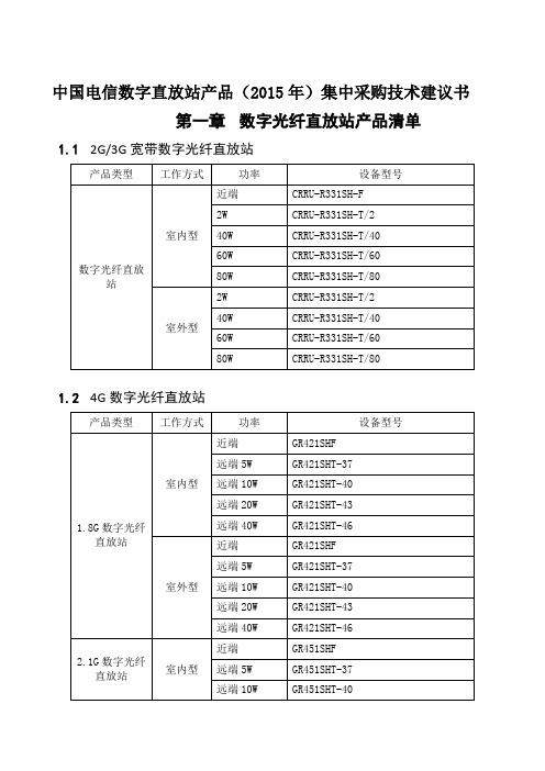
中国电信数字直放站产品(2015年)集中采购技术建议书第一章数字光纤直放站产品清单1.12G/3G宽带数字光纤直放站1.24G数字光纤直放站第二章直放站产品技术说明2.12G/3G直放站产品技术说明2.1.1设备特点●采用数字预失真技术,设备输出功率大,线性高,功耗低。
●采用数字滤波处理,增强对带外噪声和干扰的抑制。
●采用数字信号光传输技术,传输过程中不会叠加噪声,信号传输质量稳定可靠,传输距离远,可支持较远距离的室外覆盖。
●具备时延调整技术克服直放站之间重叠覆盖引起的多径干扰。
●拓扑连接方式可采用链形、星形和环形等,可以大大节约光缆资源,使系统组网方式更加灵活。
●具有本地监控、操作功能(OMT),也可接入直放站网管系统(OMC),通过基站端机内置的MODEM与OMC建立远程通信,满足运营商网管要求。
●系统具备RS-232、PSTN、Modem等多种数据传输接口,便利的遥测、遥控功能。
●光旁路功能,当设备出现故障或者掉电时,旁路器会将其旁路,其它设备不受影响。
2.1.2设备工作原理数字光纤直放站一般分为接入端与覆盖端,主要由双工器、功放、前后端数字板、数字光模块、电源模块、无线modem、监控板等组成。
其工作原理框图如图2-1所示:图2-1 分集数字光纤直放站系统工作原理框图图2-2 不分集数字光纤直放站系统工作原理框图设备在接入端由耦合器引入基站信号,由覆盖端完成无线信号的覆盖。
从基站耦合的下行信号在接入端经放大、滤波、下变频到中频后,进入数字处理单元变为数字信号,再经过电/光转换,将其调制到光信号上,通过光纤传送到覆盖端;覆盖端经过光/电转换,解调出数字信号,该信号经数字处理单元转换为中频信号,然后经上变频到射频,经滤波、放大后,通过功放和重发天线发送给移动台;反之,覆盖端重发天线接收到移动台发送的上行信号,进行低噪声放大、下变频、放大、滤波后变为中频信号,然后进入数字处理单元变为数字信号,再进行电/光转换,将其调制到光信号上,通过光纤传送回接入端,接入端先进行光/电转换,将光信号恢复成数字信号,该信号经数字处理单元转换为中频信号,然后经上变频到射频,经滤波、放大后发送给基站。
网络-迈普产品报价20051107

据需要购买光模块,但同一路的光口和电口不能同
时使用。2、闪存,16M至80M;内存128M DDR266
至1G DDR266)
MP7204/7208主控模块,不含内存,主控模块上固化
批量
由器主控卡
3640B/3680主控模块,不含内存,主控模块上固化
两个10/100/1000M电以太电口和两个1000M SFP光模
RM3A-MPU204B-1GE1FE (400KPPS)
块的插槽,主板固化16M闪存,一个闪存插槽,二个 内存插槽,CPU用BCM1125H 400M。(注:1、加
单价
迈普销售定价(含税)
市场指导 价折扣
市场指导 价
大区用户 成交限价
折扣
大区用户 成交限价
3600 5000 6000
50%
1800
50%
2500
50%
3000
40%
1440
40%
2000
40%
2400
5500
50%
2750
40%
2200
8600
50%
4300
40%
3440
10800
50%
5400
批量
RPS50-1TQ001
冗余备份电源,提供双电网冗余备份,可用于 MP269X系列、MP2600、MP1700路由器
小批量
269X路由器及可选模块
MP2632路由器,有4个模块插槽,标配2个10/100M以
MP2632(标配)
太口,64M内存,8M FLASH(EIP报价拆分为MP2632- 批量
50%
9000
50%
10000
50%
AAU5613 产品硬件培训文档-20180802-A-V1.00

快速安装型母端(免螺钉 型)连接器,即EPC9连 接器
POWER-IN端口
视供电设备而定
供电设备
DLC连接器
CPRI0/CPRI1接口
DLC连接器
BBU5900中的CPRI (SFP)接口
(1) -48V直流电流线 (2) 屏蔽层
(3) 快速安装型母端(免 螺钉型)连接器
光纤外观
(1) DLC连接器
安装 位置
抱杆
适应条件
挂墙
挂墙 抱杆
抱辅杆
安装场景
塔站 塔站
抱杆
Page 12
AAU5613 安装件、安装间距和空间要求
1. AAU5613安装件
安装件1:抱杆竖装安装件(发货默认)
2. AAU5613安装间距和空间要求
AAU5613安装间距和空间要求:AAS水平安装间距至少>=300mm,吊 装点高于天线安装点300mm;考虑到天线底部出线要求,其底部安装 空间要求>=500mm。AAU5613安装间距和空间要求参见下图所示:
将下主扣件放置于AAU下把手处,使下把手与下主扣件的 槽位对齐,然后将下主扣件的螺栓向下扣入孔位并紧固, 推荐紧固力矩为50N·m,如图4所示。
Massive MIMO AAU5613培训手册
培训目标
• 学完本课程后,您应该能:
› 掌握AAU5613产品的功能、特性 › 掌握AAU5613产品的硬件架构 › 了解AAU5613产品的安装和维护 › 掌握AAU5613产品配套策略
HIUSIALIWCOENI TSEEMCIHCONNODLUOCGTOIERS CO., LTD.
Page 8
AAU5613 接口和制式灯
项目 1
思科 WAP551 和 WAP561 Wireless-N 接入点快速入门指南说明书
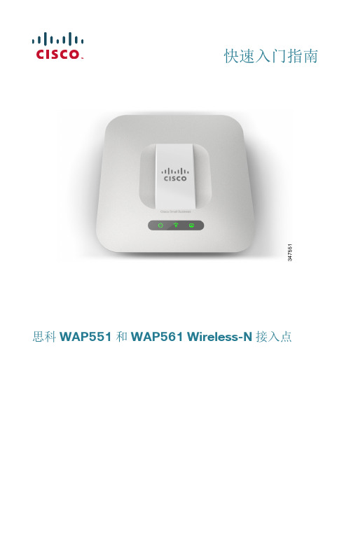
快速入门指南思科 WAP551 和 WAP561 Wireless-N 接入点欢迎感谢您选择思科 WAP551 和 WAP561 Wireless-N 接入点。
思科 WAP551 是具有单射频、可选频段、450 Mbps 数据传输率的 802.11n 接入点;思科WAP561 是思科 WAP551 的双射频版本。
本指南旨在帮助您熟悉接入点的总体布局,并为您介绍如何在网络中部署该设备以及如何配置该设备。
本指南并未涵盖接入点的所有特性和功能。
有关其他信息,请参阅《管理指南》。
在第 11 页上的“快速索引”中提供了《管理指南》的链接。
包装内容物• 无线接入点• 安装套件• 《快速入门指南》• 产品 CD• 以太网电缆• 技术支持联系信息• 中国危害性物质限制指令(仅适用于中国 SKU)配置准备1在开始安装之前,请确保以下设备和服务已就绪:• 一台支持以下浏览器的计算机:–Internet Explorer v7.0 或更高版本–Chrome v5.0 或更高版本–Firefox v3.0或更高版本–Safari v3.0或更高版本• 用于安装硬件的工具• 一台或多台带 PoE 的以太网交换机2思科 WAP551 和 WAP561 Wireless-N 接入点思科 WAP551 和 WAP561 Wireless-N 接入点3思科 WAP551 和 WAP561 Wireless-N 接入点的特性前面板设备前面板包含三个指示灯:电源、WLAN 和 LAN 。
有关这些指示灯的颜色及其指示含义的详细介绍,请参阅“验证硬件安装”。
这些指示灯下方有一个安全锁插槽。
后面板设备的后面板具有一个 RJ-45 以太网端口。
使用 PoE 功能可通过以太网端口为设备供电。
该端口是自动检测的千兆以太网 (802.3) 端口,用于将 WAP 设备连接至网络设备,如计算机、路由器或交换机。
思科强烈建议用户使用 5e 类电缆或更好的电缆进行千兆连接。
高功率新产品

PPT文档演模板
高功率新产品
HW-5618
n 产品描述
n 户外5GHz频段AP CPE n 这是一款完整的户外桥接解决方案,包含户外
箱体、无线AP/桥和平板定向天线。
– 连接搜索很快,很快搜到对方,network stumbler 的信号值为-55dbm(负值 越小越好,如-40就比-55好),自己配的软件显示信号强度为86%,信号质 量为7%~18%,用netmeter测试的数据为最大740Kbps,数据较低,考虑到后 面有一排大楼,搜索的到的AP点近20个,各种信道都有,信号强,但速 率上不来,极有可能是受到附近AP的干扰。这点上,1512具有很大的优 势。
PPT文档演模板
高功率新产品
HW-1512
n 型号:HW-1512 n 规格:IEEE 802.11b, 802.11g, 802.11n (Draft 2.0) n 收发器架构:1T2R n 频率:2.412GHz ~2.484GHz ISM频段 n LED指示灯:Active/Power n 接口:USB2.0/1.1 n 天线:PCB板载印刷天线 + 12dBi平板天线(RP-SMA接头) n 数据速率:802.11n标准:最大支持300Mbps下行带宽和150Mbps上行带宽 n 输出功率: 24 ± 2 dBm(802.11b) n 22 ± 2 dBm(802.11g) n 20 ± 2 dBm(802.11n) n 接收灵敏度:-66 dBm @ 802.11n , -76 dBm @ 54Mbps n -91 dBm @ 11Mbps , -95 dBm @ 1 Mbps n 工作范围:高达3000米,取决于周围环境 n 功耗:发送:<500mA , 接收:<300mA n 安全性:WEP(64/128bit),WPA,WPA-PSK,WPA2 TKIP/AES , WPA2-PSK , 802.1x n 操作系统:Windows 2000/XP/Vista/WIN 7/ Win CE & Linux, MAC n 尺寸:155 x 215 x 98 mm n 工作温度:0 ~ 55°C n 存储温度:-20 ~ 70°C n 湿度:5 ~90% (非冷凝)
