SML-LX0805SRC-TR中文资料
XL6005开关电流升压型LED恒流驱动器说明书

180KHz 60V 4A 开关电流升压型LED恒流驱动器XL6005特点⏹ 3.6V到32V宽输入电压范围⏹0.22V输出电流采样电压⏹VIN>=12V,可驱动11串1W LED ⏹固定180KHz开关频率⏹最大4A开关电流⏹94%以上的转换效率⏹出色的线性与负载调整率⏹EN脚TTL关机功能与PWM调光功能⏹内置功率MOS⏹内置软启动功能⏹内置频率补偿功能⏹内置热关断功能⏹内置限流功能⏹TO252-5L封装应用⏹通用LED照明⏹升压恒流驱动⏹显示器LED背光⏹7至15寸LCD面板描述XL6005是一款升压恒流型LED驱动器,具有出色的线性调整率与负载调整率,可以驱动1W/3W/5W的LED灯。
XL6005内置固定频率振荡器与频率补偿电路,简化了电路设计。
当输入电压大于等于12V时,XL6005 可直接驱动11串1W LED。
PWM控制环路可以调节占空比从0~90%之间线性变化。
内置使能功能、过电流保护功能。
内部补偿模块可以减少外围元器件数量。
图1. XL6005封装180KHz 60V 4A 开关电流升压型LED 恒流驱动器 XL6005引脚配置FB SW EN GNDVIN 12345TO252-5L图2.XL6005引脚配置表1.引脚说明引脚号 引脚名称 描述1 GND 接地引脚。
2 EN 使能引脚,低电平关机,高电平工作,悬空时为高电平。
3 SW 功率开关输出引脚,SW 是输出功率的开关节点。
4 VIN 电源输入引脚,支持DC3.6V 到32V 范围电压输入,需要在 VIN 与GND 之间并联电解电容以消除噪声。
5FB反馈引脚,参考电压为0.22V 。
180KHz 60V 4A 开关电流升压型LED 恒流驱动器 XL6005方框图NDMOSVINSWGNDFB2.5V 0.22VCOMP2.5V Regulator 0.22V ReferencePhase CompensationRS LatchUVLOSoft StartThermal ShutdownEAEA ∑Driver OCPOVPENOscillator180KHzSlop Compensation图3.XL6005方框图典型应用XL6005CIN 47uF 25VD1 SS36L1 47uh/3A+12V41253GNDVINSWFBENON OFFI LED =0.22/RSRS 350mASeries 11 1W LEDCOUT 47uF 50VC1105C2105图4.XL6005系统参数测量电路180KHz 60V 4A开关电流升压型LED恒流驱动器XL6005 订购信息产品信号打印名称封装方式包装类型XL6005E1 XL6005E1 TO252-5L 2500只每卷XLSEMI无铅产品,产品型号带有“E1”后缀的符合RoHS标准。
瑞萨电子单芯片电表方案
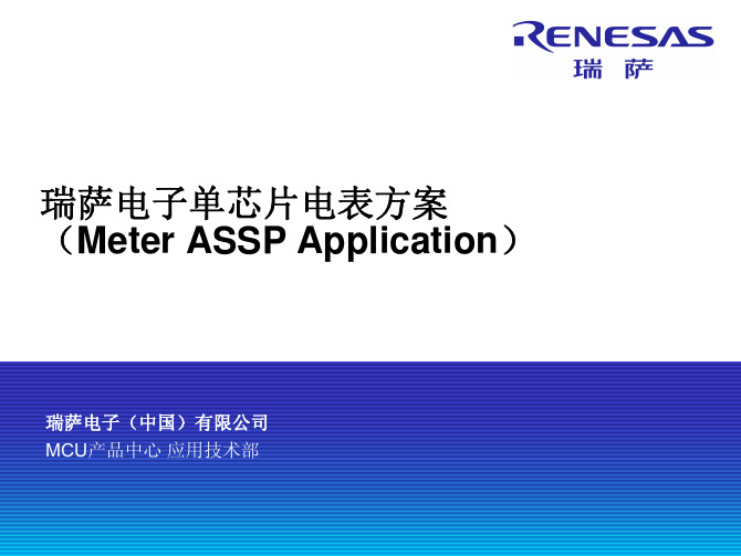
78K0/Lx3-M的资源
按键扫描功能 异步串行通讯口UART6 异步串行通讯口UART0 专用的红外发射电路 LCD 驱动电路 低电压检测LVI 10位A/D转换器 外部中断输入 按键输入 RTC和温度校正 温度检测硬件 电能计量模块的功能 子芯片通讯模块
3
© 2010 Renesas Electronics Corporation. All rights reserved.
78K0/Lx3-M结构框图
主芯
K0
RAM RAM Cluster Cluster FLASH FLASH Cluster Cluster
RAMIF
外围器件
10位AD 温度传感器 TM0 x1通道
子芯 子芯
NEW NEW NEW NEW NEW NEW
24位 ⊿ΣADC
FCB 60K 60K
CIB
--电压信号过零点检测和过零点超时 --峰值检测 --失压检测 --周期和频率测量 --防窃电功能
4
© 2010 Renesas Electronics Corporation. All rights reserved.
方案特点
最大的特点:单芯片
MCU LCD驱动
传统方案
电能计量 MCU RTC
温度传感器
MINICUBE2
异步串口UART0
RS485模块
7
© 2010 Reon. All rights reserved.
ASSP电能表实物图
演示板
通信电缆
8
© 2010 Renesas Electronics Corporation. All rights reserved.
电能计量
1K 1K 1K 1K
LMX2541-xxxx评估板用户指南说明书

LMX2541-xxxx Evaluation Board User's GuideSeptember 2004Literature Number SNAU067ARevised – January 2014LMX2541xxxxUltra Low Noise PLLatinum™ Frequency Synthesizer with Integrated VCO Evaluation Board Operating InstructionsT ABLE OF C ONTENTSE QUIPMENT .................................................................... E RROR!B OOKMARK NOT DEFINED.B ASIC O PERATION (5)LMX2541XXXX B OARD I NFORMATION (7)A PPENDIX A:B OARD S TACKUP L AYERS (14)A PPENDIX B:B ILL OF M ATERIALS................................. E RROR!B OOKMARK NOT DEFINED.15 A PPENDIX C:S CHEMATICS........................................... E RROR!B OOKMARK NOT DEFINED.16 A PPENDIX D:A SSEMBLY D IAGRAM............................... E RROR!B OOKMARK NOT DEFINED.17 A PPENDIX E:Q UICK S TART ON EVMC OMMUNICATION. E RROR!B OOKMARK NOT DEFINED.22EquipmentPower SupplyThe Power Supply should be a low noise power supply. An Agilent 6623A Triple power supply with LC filters on the output to reduce noise was used in creating these evaluation board instructions.Signal GeneratorThe Signal Generator should be capable of frequencies and power level required for the part. A Rohde & Schwarz SML03 was used in creating these evaluation board instructions.Phase Noise / Spectrum AnalyzerFor measuring phase noise an Agilent E5052A is recommended. An Agilent E4445A PSA Spectrum Analyzer with the Phase Noise option is also usable although the architecture of the E5052A is superior for phase noise measurements. At frequencies less than 100 MHz the local oscillator noise of the PSA is too high and measurements will be of the local oscillator, not the device under test.OscilloscopeThe oscilloscope and probes should be capable of measuring the output frequencies of interest when evaluating this board. The Agilent Infiniium DSO81204A was used in creating these evaluation board instructions.Basic Operation1. Connect a low noise 3.3 V power supply to the Vcc connector located at the top left of the board.2. Please see Appendix D for quick start on interfacing the board. Connect PC to the uWire header.Laptop or PC Power SupplyPower CablePower Cable 3.3 V2Please see Appendix D for interface infoPlease see Appendix D for interface info 1VccuWireheader3. Start CodeLoader4.exe.4. Select USB or LPT Communication Mode on the Port Setup tab as appropriate.5. Click “Select Device” →“PLL-VCO” → LMX2531xxxx depending on which chip is on your board.6. Check your window with “PLL/VCO” Tab screenshot, 100 MHz input, but VCO output will be different dependingon which LMX2541xxxx you selectedLMX2541-xxxx Board Information* Note that the VCO gain does change a fair amount. Although not demonstrated in these instructions, the charge pump gain could be adjusted to account for this variation.LMX2541SQ2060E Setup and Measured PerformanceLMX2541SQ2380E Setup and Measured ResultsLMX2541SQ2690E Setup and Measured ResultsLMX2541SQ3030E Setup and Measured ResultsLMX2541SQ3320E Setup and Measured REsultsLMX2541SQ3740E Setup and Measured ResultsAppendix A: Board Stackup LayersAppendix B: Bill of MaterialsAppendix E: Quick Start on EVM Communication Codeloader is the software used to communicate with the EVM (Please download the latest version from - /tool/codeloader). This EVM can be controlled through the uWire interface on board. There are two options in communicating with the uWire interface from the computer.OPTION 1Open Codeloader.exe →Click “Select Device” →Click “Port Setup” tab →Click “LPT” (in Communication Mode) OPTION 2SNAU067 LMX2541-xxxx Evaluation Board User’s Guide Revised – January 2014 22Copyright © 2013, Texas Instruments IncorporatedThe Adapter BoardExample adapter configuration (LMK01801)Open Codeloader.exe →Click “Select Device” →Click “Port Setup” Tab →Click “USB” (in Communication Mode) *Remember to also make modifications in “Pin Configuration” Section according to Table above.Revised – January 2014 LMX2541-xxxx Evaluation Board User’s Guide SNAU067 23Copyright © 2013, Texas Instruments IncorporatedIMPORTANT NOTICETexas Instruments Incorporated and its subsidiaries(TI)reserve the right to make corrections,enhancements,improvements and other changes to its semiconductor products and services per JESD46,latest issue,and to discontinue any product or service per JESD48,latest issue.Buyers should obtain the latest relevant information before placing orders and should verify that such information is current and complete.All semiconductor products(also referred to herein as“components”)are sold subject to TI’s terms and conditions of sale supplied at the time of order acknowledgment.TI warrants performance of its components to the specifications applicable at the time of sale,in accordance with the warranty in TI’s terms and conditions of sale of semiconductor products.Testing and other quality control techniques are used to the extent TI deems necessary to support this warranty.Except where mandated by applicable law,testing of all parameters of each component is not necessarily performed.TI assumes no liability for applications assistance or the design of Buyers’products.Buyers are responsible for their products and applications using TI components.To minimize the risks associated with Buyers’products and applications,Buyers should provide adequate design and operating safeguards.TI does not warrant or represent that any license,either express or implied,is granted under any patent right,copyright,mask work right,or other intellectual property right relating to any combination,machine,or process in which TI components or services are rmation published by TI regarding third-party products or services does not constitute a license to use such products or services or a warranty or endorsement e of such information may require a license from a third party under the patents or other intellectual property of the third party,or a license from TI under the patents or other intellectual property of TI.Reproduction of significant portions of TI information in TI data books or data sheets is permissible only if reproduction is without alteration and is accompanied by all associated warranties,conditions,limitations,and notices.TI is not responsible or liable for such altered rmation of third parties may be subject to additional restrictions.Resale of TI components or services with statements different from or beyond the parameters stated by TI for that component or service voids all express and any implied warranties for the associated TI component or service and is an unfair and deceptive business practice. TI is not responsible or liable for any such statements.Buyer acknowledges and agrees that it is solely responsible for compliance with all legal,regulatory and safety-related requirements concerning its products,and any use of TI components in its applications,notwithstanding any applications-related information or support that may be provided by TI.Buyer represents and agrees that it has all the necessary expertise to create and implement safeguards which anticipate dangerous consequences of failures,monitor failures and their consequences,lessen the likelihood of failures that might cause harm and take appropriate remedial actions.Buyer will fully indemnify TI and its representatives against any damages arising out of the use of any TI components in safety-critical applications.In some cases,TI components may be promoted specifically to facilitate safety-related applications.With such components,TI’s goal is to help enable customers to design and create their own end-product solutions that meet applicable functional safety standards and requirements.Nonetheless,such components are subject to these terms.No TI components are authorized for use in FDA Class III(or similar life-critical medical equipment)unless authorized officers of the parties have executed a special agreement specifically governing such use.Only those TI components which TI has specifically designated as military grade or“enhanced plastic”are designed and intended for use in military/aerospace applications or environments.Buyer acknowledges and agrees that any military or aerospace use of TI components which have not been so designated is solely at the Buyer's risk,and that Buyer is solely responsible for compliance with all legal and regulatory requirements in connection with such use.TI has specifically designated certain components as meeting ISO/TS16949requirements,mainly for automotive use.In any case of use of non-designated products,TI will not be responsible for any failure to meet ISO/TS16949.Products ApplicationsAudio /audio Automotive and Transportation /automotiveAmplifiers Communications and Telecom /communicationsData Converters Computers and Peripherals /computersDLP®Products Consumer Electronics /consumer-appsDSP Energy and Lighting /energyClocks and Timers /clocks Industrial /industrialInterface Medical /medicalLogic Security /securityPower Mgmt Space,Avionics and Defense /space-avionics-defense Microcontrollers Video and Imaging /videoRFID OMAP Applications Processors /omap TI E2E Community Wireless Connectivity /wirelessconnectivityMailing Address:Texas Instruments,Post Office Box655303,Dallas,Texas75265Copyright©2015,Texas Instruments Incorporated。
贴片压敏电阻0805封装参数型号规格书大全

UN Semiconductor Co., Ltd.
Revision December 18, 2013
3/5
@ UN Semiconductor Co., Ltd. 2013
MULTILAYER CHIP VARISTORS
UN0805-XXXH Series
Packaging Specification
hours, the change of varistor voltage shall be within 10%.
Damp Heat Load/ Humidity Load
The specimen should be subjected to 40℃,90 to 95%RH environment, and the maximum allowable voltage applied for 1000 hours, then stored at room temperature and humidity for one or two hours. The change of varistor voltage shall be within 10%.
machine. And a normal paper tape shall be connected in the head of taping for the operator handle.
type
0402 0603 0805 1206 1210 1812 2220 3220
A0 ±0.10
1.08
B0
K0
±0.10 ±0.10
1.88 1.04
T ±0.05 0.22
T2
D0
±0.05 +0.10
XL8005开关电流降压型PFM LED恒流驱动器说明书
100V 0.5A 开关电流降压型PFM LED恒流驱动器XL8005特点⏹24V到100V宽输入电压范围⏹0.2V输出电流采样电压⏹输出可驱动3~8串1W LED ⏹出色的线性与负载调整率⏹96%以上转换效率⏹最小压降6V⏹内置高压功率MOS⏹内置热关断功能⏹内置欠压保护功能⏹内置限流功能⏹内置LED开路短路保护功能⏹内置软启动功能⏹SOP8封装应用⏹EBIKE LED照明⏹LED照明与LED灯⏹通用照明描述XL8005是一款带有PFM的高压开关稳压器,可工作在DC24V到100V输入电压范围。
XL8005是一款高效的LED驱动器开关调节器。
LED灯是恒流驱动的而非恒压驱动,提供恒定电流输出,增强可靠性。
图1. XL8005封装100V 0.5A 开关电流降压型PFM LED 恒流驱动器 XL8005引脚配置XL800513524VINNC CSP VDD SW678VIN CSNCSN图2. XL8005引脚配置表1.引脚说明引脚号 引脚名 描述1 NC 无连接。
2 VDD 芯片电源电压引脚。
3 CSP 电流检测正端引脚。
4 SW 功率开关输出引脚,SW 是输出功率的开关节点。
5,6 VIN 电源输入引脚,支持24V 到100V DC 范围电压输入。
7,8 CSN电流检测负端引脚。
100V 0.5A 开关电流降压型PFM LED 恒流驱动器 XL8005方框图CSN3.3V 0.2VCOMPPFMReference VoltageUVLOLatch and DriverThermal ShutdownVINVDDSWOCPEAEA Frequency CompensationSoft Start Circuit0.22VCSP120V DMOS图3. XL8005方框图典型应用XL8005R1 330KDF S210CSNRCS 0.68ΩL11mh/0.6ACout 100uf/35VILED=0.2V/RCSOutput Series 3~8 * 1W LEDVDDDC 24V~100VCSP C12.2uF VINCeramic245,67,8[1] Input DC 24V~100V.[2] Output Constant Current Drive Series 3~8 * 1W LED.[3] Support Output LED Open & Short Protection.DD BAV21WCin 33uf/100VR230K 0.25W3SW图4. XL8005系统参数测量电路(3W~8W LED 灯)100V 0.5A开关电流降压型PFM LED恒流驱动器XL8005订购信息产品型号打印名称封装方式包装类型XL8005E1 XL8005E1 SOP8 2500只每卷XLSEMI无铅产品,产品型号带有“E1”后缀的符合RoHS标准。
0805共模电感规格书

A
B
Epoxy
C
Terminations Wires
①
④
(0.4)
②
(0.45)
(0.4)
③
(0.45)
Equivalent circuit
①
④
②
③
No Polarity
A : 2.0 ± 0.2 B : 1.2 ± 0.2 C : 1.2 ± 0.2
Drawn by Checked by Approved by
(1) Product name (2) Shapes and dimensions (3) Shielding Type (4) Impedance【 at 100MHz】
900:90Ω (5) Number of Line
2P:2-Line (6) Taping Type
3. Shapes and Dimensions [Dimensions in mm]
Measurement terminal
①
④
②
③
PRODUCT SPECIFICATION
5.Reliability Test
6/10 SPEC. NO.
T-0602-001T
Operating temperature : -25 to +85℃
Storage temp and humidity : 20~25℃ ,60%RH max.
1000 100
CMF2012F-400-2P-T
Common Mode Differential Mode
Insulation Resistance (MΩ)Min.
10 10 10 10 10 10 10 10 10 10 10 10 10 10 10 10
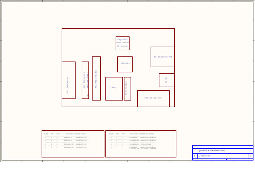
具备IEEE 1588和光纤模式的以太网收发器DP83640原理图
IMPORTANT NOTICETexas Instruments Incorporated and its subsidiaries(TI)reserve the right to make corrections,modifications,enhancements,improvements, and other changes to its products and services at any time and to discontinue any product or service without notice.Customers should obtain the latest relevant information before placing orders and should verify that such information is current and complete.All products are sold subject to TI’s terms and conditions of sale supplied at the time of order acknowledgment.TI warrants performance of its hardware products to the specifications applicable at the time of sale in accordance with TI’s standard warranty.Testing and other quality control techniques are used to the extent TI deems necessary to support this warranty.Except where mandated by government requirements,testing of all parameters of each product is not necessarily performed.TI assumes no liability for applications assistance or customer product design.Customers are responsible for their products and applications using TI components.To minimize the risks associated with customer products and applications,customers should provide adequate design and operating safeguards.TI does not warrant or represent that any license,either express or implied,is granted under any TI patent right,copyright,mask work right, or other TI intellectual property right relating to any combination,machine,or process in which TI products or services are rmation published by TI regarding third-party products or services does not constitute a license from TI to use such products or services or a warranty or endorsement e of such information may require a license from a third party under the patents or other intellectual property of the third party,or a license from TI under the patents or other intellectual property of TI.Reproduction of TI information in TI data books or data sheets is permissible only if reproduction is without alteration and is accompanied by all associated warranties,conditions,limitations,and notices.Reproduction of this information with alteration is an unfair and deceptive business practice.TI is not responsible or liable for such altered rmation of third parties may be subject to additional restrictions.Resale of TI products or services with statements different from or beyond the parameters stated by TI for that product or service voids all express and any implied warranties for the associated TI product or service and is an unfair and deceptive business practice.TI is not responsible or liable for any such statements.TI products are not authorized for use in safety-critical applications(such as life support)where a failure of the TI product would reasonably be expected to cause severe personal injury or death,unless officers of the parties have executed an agreement specifically governing such use.Buyers represent that they have all necessary expertise in the safety and regulatory ramifications of their applications,and acknowledge and agree that they are solely responsible for all legal,regulatory and safety-related requirements concerning their products and any use of TI products in such safety-critical applications,notwithstanding any applications-related information or support that may be provided by TI.Further,Buyers must fully indemnify TI and its representatives against any damages arising out of the use of TI products in such safety-critical applications.TI products are neither designed nor intended for use in military/aerospace applications or environments unless the TI products are specifically designated by TI as military-grade or"enhanced plastic."Only products designated by TI as military-grade meet military specifications.Buyers acknowledge and agree that any such use of TI products which TI has not designated as military-grade is solely at the Buyer's risk,and that they are solely responsible for compliance with all legal and regulatory requirements in connection with such use. TI products are neither designed nor intended for use in automotive applications or environments unless the specific TI products are designated by TI as compliant with ISO/TS16949requirements.Buyers acknowledge and agree that,if they use any non-designated products in automotive applications,TI will not be responsible for any failure to meet such requirements.Following are URLs where you can obtain information on other Texas Instruments products and application solutions:Products ApplicationsAudio /audio Automotive and Transportation /automotiveAmplifiers Communications and Telecom /communicationsData Converters Computers and Peripherals /computersDLP®Products Consumer Electronics /consumer-appsDSP Energy and Lighting /energyClocks and Timers /clocks Industrial /industrialInterface Medical /medicalLogic Security /securityPower Mgmt Space,Avionics and Defense /space-avionics-defense Microcontrollers Video and Imaging /videoRFID OMAP Mobile Processors /omapWireless Connectivity /wirelessconnectivityTI E2E Community Home Page Mailing Address:Texas Instruments,Post Office Box655303,Dallas,Texas75265Copyright©2012,Texas Instruments Incorporated。
SML-812MT中文资料

LEDs, Surface Mount CHIP - standard
Case & Viewing Angle Peak Wavelength nm Typ. Luminous Intensity Chip (IF = 20mA) Height mcd (H) mm
OPTOELECTRONICS
Emitted Colour NORMAL BRIGHTNESS Red Red Orange Yellow Green Green Green Pure-Green HIGH BRIGHTNESS Red Red Orange Orange Yellow Yellow Green Green Green* Green* Blue* Blue* Blue*
Typ. Luminous Intensity Chip (IF = 20mA) Height mcd (H) mm
Manf. Part No. & Order Code
Dimensions (mm)
2.0 1.4
0805 Chip
Red Red Orange Yellow Green Pure-Green HIGH BRIGHTNESS Red Orange Yellow
0.8
1.0 0.8 0.3 1.0
0.3
Viewing angle 170°
Red Orange Yellow Green
white-diffused white-diffused white-diffused white-diffused
632 611 593 570
45 45 45 30
TOL1608MRB TOL1608MOB TOL1608MYB TOL1608MGB
SML-512MW中文资料
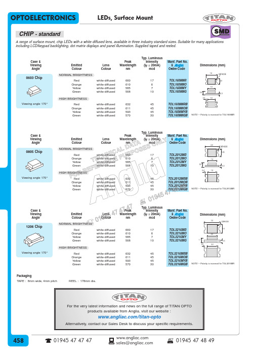
LEDs, Surface Mount CHIP - standard
Case & Viewing Angle Peak Wavelength nm Typ. Luminous Intensity Chip (IF = 20mA) Height mcd (H) mm
OPTOELECTRONICS
Emitted Colour NORMAL BRIGHTNESS Red Red Orange Yellow Green Green Green Pure-Green HIGH BRIGHTNESS Red Red Orange Orange Yellow Yellow Green Green Green* Green* Blue* Blue* Blue*
*These LEDs are electrostatic sensitive devices. Observe precautions for handling
Case & Viewing Angle
Emitted Colour NORMAL BRIGHTNESS
Lens Colour
Peak Wavelength nm
Typ. Luminous Intensity Chip (IF = 20mA) Height mcd (H) mm
Manf. Part No. & Order Code
Dimensions (mm)
2.0 1.4
0805 Chip
Red Red Orange Yellow Green Pure-Green HIGH BRIGHTNESS Red Orange Yellow
1.8
Packaging TAPE : 8mm wide, 4mm pitch REEL : 178mm dia.
单片机应用技术1 单片机硬件基础
复位电路
AT89S51最小系统之ROM选择
51单片机内部集成有4K字节的 程序存储器(标准型),可以外 接存储器芯片扩展容量。 EA=0时:不使用内部ROM, 外部地址从0开始。 EA=1时:内+外。超过内部 地址后自动使用外部ROM地址, 内外的地址连续。 根据程序编译后的代码长度考 虑选择不同内部ROM容量的单片 机型号。故EA固定为高电平。
AT:(美)ATMEL公司 P:(荷)Philips公司 STC:(大陆)宏晶科技 W:(台)华邦公司
0343:2003年43周制 造
AT89S51封装形式
PLCC44
TQFP44式封装。 PLCC44:特殊引脚芯片塑料封装,贴片封 装的一种,引脚在芯片底部向内弯曲,焊接 采用回流焊工艺,在调试时有插座可用。 TQFP44:薄四方扁平封装,低成本,低高 度引线框封装,适合用SMT表面安装技术。
PDIP40封装
端口的几个操作注意点
1.驱动能力不同,P0每引脚可以驱动8个TTL负载, 其余端口每引脚只能带4个。
2.P0口内部无上拉电阻,其余口有弱上拉,电路设计 时需要注意P0口漏极开路,做IO输出时,需外加上 拉电阻才会有高电平输出。
3.P0在做数据线时才是真正的双向口 P0-P3在做输入接口时,需要先置1再读入(打 开内部锁存器)
AT89S51
PDIP40 封装
AT89S51
PLCC44封装
注:NC表示该脚无用
AT89S51
TQFP44封装
注:NC表示该脚无用
AT89S51引脚功能
P0/P1/P2/P3:
4个并行端口,每口8脚,可做IO接口, 也可做第二功能;
IO功能:
输入输出引脚,用户灵活DIY
LED恒流驱动IC参数表

品牌 型号 驱动 封装型式 类型 DC/DC SOT89-5 Buck DC/DC SOT23-5 Buck 输入电 输出电压 压(V) (V) 工作频 工作温 输出电流 LED灯数 调光方式 率 度 效率 (KHz) (℃) ≤1A 1~10串 PWM 1M -40~85 97%
应用
应用 MR16,MR11,投光 灯,洗墙灯,舞台 灯,车灯等低压照明 MR16,MR11,投光 灯,洗墙灯,舞台 灯,车灯等低压照明 手电筒,太阳能灯, 台灯,矿灯,相机闪 光灯 广泛应用于E14 / E27 / PAR30 / PAR38 / GU10 等灯 杯和 LED 日光 灯。 PAR30/GU10/E27 LED 射灯、球泡灯 LED 洗墙灯 LED 信动 封装型式 类型 DC/DC TO-94 Boost DC/DC TO-92 Boost DC/DC SOT89-5 Buck DC/DC SOT89-5 Buck AC/DC or SOP8 DC/DC Buck DC/DC SOT89-5 Buck DC/DC SOP8-EP Buck DC/DC SOP8 Boost
工作频 工作温 率 度 效率 (KHz) (℃) 180 -40~105 94%
XLSEMI XL6005
5~40
≤52
5A
PWM
PowTech PT4115B89E ADDtek A705NGT-250
6~30 2.7~12 2.7~6 2.7~6 5~50
4-40
≤28.5
1.2A 250±10mA 340~380 300~340
功率因素校正IC,应 用于日光灯,球泡 灯,开关电源等方案
SML-210中文资料

The products listed in this document are designed to be used with ordinary electronic equipment or devices (such as audio visual equipment, office-automation equipment, communications devices, electrical appliances and electronic toys). Should you intend to use these products with equipment or devices which require an extremely high level of reliability and the malfunction of with would directly endanger human life (such as medical instruments, transportation equipment, aerospace machinery, nuclear-reactor controllers, fuel controllers and other safety devices), please be sure to consult with our sales representative in advance. About Export Control Order in Japan Products described herein are the objects of controlled goods in Annex 1 (Item 16) of Export Trade Control Order in Japan. In case of export from Japan, please confirm if it applies to "objective" criteria or an "informed" (by MITI clause) on the basis of "catch all controls for Non-Proliferation of Weapons of Mass Destruction.
HZX-0805红灯规格书
测试条件 IF = 20mA IF = 20mA
峰值波长
λP
---
645
---
nm
IF = 20mA
主波长
λD
--635-
--650-
nm
IF = 20mA
半波宽
Δλ
--
15
---
nm
IF=20mA
正向电压
VF
1.8
---
2.6
V
IF=20mA
反向电流
IR
---
---
5
uA
VR=5V
亮度分 BIN 规格
九、 圆盘及载带卷出方向及空穴规格:
十、内包装及外包装:
内标签
干燥剂
外标签
圆盘
防潮防静电袋
抽真空、热封
5 cartons/box
10 bags/carton
深圳市恒智兴电子科技有限公司
SHENZHEN HENGZHIXING ELECTRONICS TECHNOLOGY.
十一、信赖性实验:
类别 测试项目
2
2.0
2.2
3
2.2
2.4
4
2.4
2.6
波长分 BIN 规格
Bin
Min
E
635
F
640
G
645
Max
640 645 650
六、 光电参数代表值特征曲线:
V
IF=20mA
Unit
Condition
nm
IF=20mA
深圳市恒智兴电子科技有限公司
SHENZHEN HENGZHIXING ELECTRONICS TECHNOLOGY.
PRC0805中文资料
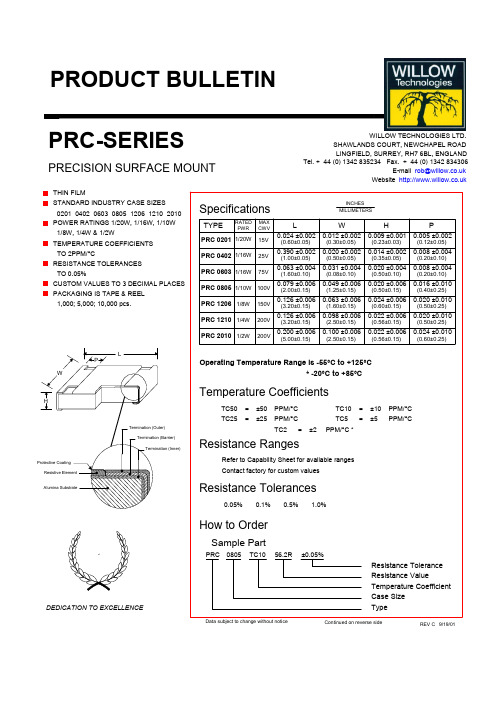
= =
±50 ±25
PPM/°C PPM/°C TC2 = ±2
TC10 TC5 PPM/°C *
= =
±10 ±5
PPM/°C PPM/°C
Resistance Ranges
Refer to Capability Sheet for available ranges Contact factory for custom values
元器件交易网
TYPICAL RELIABILITY TEST DATA AND SPECIFICATIONS
Characteristic
MOISTURE LOAD LIFE
Test Conditions 60°C 95%RH Rated voltage for 1½ hours ON, ½ hour OFF. 1000 hours -55°C~RT~ +155°C~RT 30 min. ON 3 min. OFF 5 cycles 175°C No load 1000 hours 10~50Hz 3 directions each 2 hours Acceleration 50G Axis 11 msec. x 3 Total 18 cycles Solder temperature 275°C for 20 sec. ±1sec. Solder temperature 230°C ±5°C for 3 sec. ±1 sec. 2.5 times to rated voltage for 5 seconds 60°C, 95%RH No load 1000Hour 70°C Rated voltage for 1½ hours ON, ½ hour OFF. 1000 hours
75V
SRR0805-680K中文资料
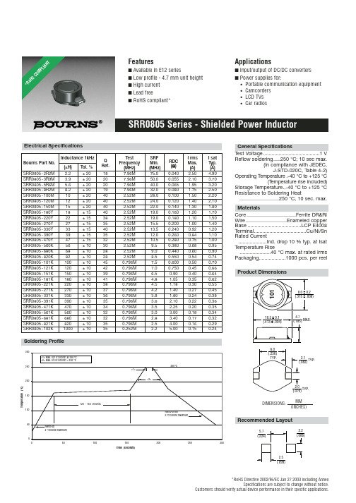
Electrical Specifications
Inductance 1kHz
Bourns Part No. (µH) Tol. %
Q Ref.
SRR0805 - 2R2M 2.2
± 20
18
SRR0805 - 3R9M 3.9
± 20
20
SRR0805 - 5R6M 5.6
± 20
20
SRR0805 - 8R2M 8.2
Soldering Profile
300 <1> Max. of 10 seconds at 250 °C <2> Max. of 30 seconds > 220 °C
250
200
<1> <2>
250 °C
150
100
50
0 0
Ramp-up 4 °/second maximum
50
120 - 150 seconds 100
■ Input/output of DC/DC converters
■ Power supplies for: • Portable communication equipment • Camcorders • LCD TVs • Car radios
SRR0805 Series - Shielded Power Inductor
SRF Min. (MHz) 75.0 50.0 40.0 32.0 28.0 24.0 22.0 19.0 19.0 15.5 13.5 12.0 10.5 9.5 9.0 8.5 7.5 7.0 6.5 4.8 4.5 4.2 3.8 3.6 3.5 3.0 2.8 2.5 2.2
0805LED灯珠翠绿色贴片LED灯珠0805规格书
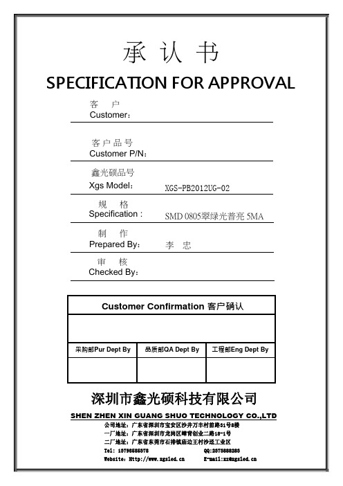
Customer:·Technical Data Sheet PN:XGS-PB2012UG-02 For:IF=5mAContents1.Features2.Applications3.Package dimensions4.Absolute maximum rating5.Electrical optical characteristics6.BIN range7.Package label8.Soldering pad dimensions9.Soldering conditions10.Package tape specifications11.T ypical electro-optical characteristics curves12.Reliability test items and conditions13.Cautions14.Note◆F eatures:Compatible with automatic placement equipmentCompatible with reflow solder processLow power consumption and wide viewing angleThis product doesn’t contain restriction Substance, comply ROHS standard.◆A pplications:Automotive and TelecommunicationFlat backlight for LCD ,switch and symbol in telephone and faxGeneral use for indicators◆P ackage Dimensions:Unit:mmTolerenc e±0.1Electrodes: Ag Plating◆A bsolute Maximum Rating (Ta=25℃)* I FP condition: pulse width ≤1ms ,duty cycle ≤1/10◆E lectrical Optical Characteristics(Ta=25℃)Notes: 1.Tolerance of Luminous Intensity ±10%2.Tolerance of Dominant Wavelength ±2nm3.Tolerance of Forward Voltage ±0.05V4.Luminous Intensity is measured by XGSLED’s equipment on bare chips◆S oldering Pad Dimensions:◆ S oldering Conditions (Maximum allowable soldering conditions)Reflow soldering profile <Pb-free solder>Time• Reflow soldering should not be done more than two times. • Do not stress its resin while soldering.• After soldering,do not warp the circuit board.T e m p e r a t u r e◆ P ackage Tape Specifications: (3000 pcs/Reel)Reel Lead Min.60mm No LEDs5 Reels in one Box10 Boxes in one Carton◆ T ypical Electro-Optical Characteristics Curves :Forward Current Vs Ambient Temperature5040302010100250Forward Current Vs Relative Luminosity204060801001020304050Ambient Temperature Ta (° C)Forward Current (mA)200 15010050 Relative Luminosity VsAmbient TemperatureIf=15mA-50° -60°-70°-80°-90°-40°-30°-20°-10°0°10°20°30°40°50°60°70°80°90° 0 0204060801001.00.50.5Radiation Angle1.0Ambient Temperature Ta (° C)R e l a t i v e L u m i n o s i t y (%)F o r w a r d C u r r e n t (m A )R e l a t i v e L u m i n o s i t y (%)◆Reliability(1)Test Items and Conditions(2)C riteria of judging the damage◆C autions1、PackageWhen moisture is absorbed into the package it may vaporize and expand during soldering. There is apossibility that this can cause exfoliation of the contacts and damage to the optical characteristics of the LEDs. So the moisture proof package is used to keep moisture to a minimum in the package.2、StorageBefore opening the package: The LEDs should be kept at 5~30°C and 60%RH or less. The LEDs should be used within a year.After opening the package: The LED must be used within 24 hours, else should be kept at 5~30℃and 30% RH or less. The LEDs should be used within 7days after opening the package. If unused LEDs remain, they should be stored in moisture proof packages, recommended to return the LEDs to the original moisture proof bag and to reseal the moisture proof bag again.If the LEDs have exceeded the storage time, baking treatment should be performed more than 24hours at 60±5°C.3、Soldering IronEach terminal is to the tip of soldering iron temperature less than 300℃ for 3 seconds within once inless than the soldering iron capacity 25 W.Leave two seconds and more internals, and do soldering of each terminal. Be careful because the damage of the product is often started at the time of the hand solder.4、RepairingRepairing should not be done after the LEDs have been soldered. When repairing is unavoidable, a double-head soldering iron should be used (as below figure). It should be confirmed beforehand whether the characteristics of the LEDs will or will not be damaged by repairing.5、The LED electrode sections are comprised of a gold plated. The gold surface may be affected by environments which contain corrosive gases and so on. Please avoid conditions which may cause the LED to corrode or discolor. This corrosion or discoloration may cause difficulty during soldering operations. It is recommended that the User use the LEDs as soon as possible.6、Please avoid rapid transitions in ambient temperature, especially in high humidity environments where condensation can occur.◆N otes:1、Above specification may be changed without notice. We will reserve authority on material change for above specification.2 、When using this product, please observe the absolute maximum ratings and the instructions for the specification sheets. We assume no responsibility for any damage resulting from use of the product which does not comply with the instructions included in the specification sheets.。
RC0805资料

Thick Film Chip Resistor – General PurposeFeatures• Small and light weight• Excellent heat resistance and moisture resistance• Suitable size and packaging for surface mount assembly • RoHS CompliantApplications• For general purpose applications• For laptop and notebook computer, memory module, digital camera and telecommunication equipmentAbsolute Maximum Ratings & CharacteristicsProductNumbermm TolerancePower Rating @70˚CMAX Working Voltage MAXOverload VoltageTCR ppm/℃Resistance RangeRated WorkingTemperature±200 1Ω ~ 9.76Ω±100 10Ω ~ 1M ΩRC0805 2012J: ±5%F: ±1%1/8W 150V 300V ±2001.02M Ω ~ 10M Ω-55℃~+155℃*JumperProduct NumberJumper Rated CurrentResistanceRated Working Temperature RC0805 2A 50m Ω (max.)-55℃~+155℃RC0805 Power Derating CurveFor resistors operate in the ambient temperature over 70˚C, loading power ratio will de-rate in accordance with following curve.Soldering ConditionIR Reflow soldering Wave soldering (flow soldering)RC0805 Dimensions (in mm)ProductNumbermm L W H A BAverageWeight RC08052012 2.00 ± 0.101.25± 0.100.50 ± 0.100.35 ± 0.200.40 ± 0.20 4.54 mg Marking(1) ±5% Tolerance (J): 3 digits, the first two digits are significant figures; the third digit is numberof zeros to follow. Letter “R” is as decimal point; Letter “0” for jumper.(2) ±1% Tolerance (F): 4 digits, the first three digits are significant figures; the fourth digit isnumber of zeros. Letter “R” is as decimal point; Letter “0” for jumper.Examples:3 digits marking (±5%)4 digits marking (±1%)683 = 68x103Ω Jumper 6812 = 681x102Ω= 68000 Ω = 68KΩ = 68100 Ω = 68.1KΩ7R5 = 7.5 ΩRC0805 Test and RequirementsRequirement Test Item Test Method Test Condition±1% ±5% JumperTemperature Coefficient of Resistance(T.C.R.) JIS C 5201 4.8IEC 60115-1 4.8-55°C~+155,20°C isthe referencetemperatureWithin the specificationShort Time Overload JIS C 5201 4.13IEC 60115-1 4.132.5 times RCWV or max.overload voltage for 5seconds±(1.0%+0.05Ω) ±(2.0%+0.05Ω) <50mΩInsulation Resistance JIS C 5201 4.6IEC 60115-1 4.6Max. overload voltagefor 1 minute≥10GVoltage Proof JIS C 5201 4.7IEC 60115-1 4.71.42 times RCWV(RMS) for 1 minuteno breakdown or flashoverSubstrate Bending Test JIS C 5201 4.33IEC 60115-1 4.33Bending once with 5seconds for 3 mm±(1.0%+0.05Ω) ±(1.0%+0.05Ω) <50mΩResistance to soldering heat JIS C 5201 4.18IEC 60115 4.18260±5°C for 10 seconds±(0.5%+0.05Ω) ±(1.0%+0.05Ω) <50mΩLeaching JIS C 5201 4.18IEC 60115 4.18260±5°C for 60 seconds no leachingSolderability JIS C 5201 4.17IEC 60115-1 4.17245±5°C for 3 seconds. >95% coverageEndurance at upper category temperature JIS C 5201 4.23IEC 60115-1 2.23.2at +155°C for 1000 hrs ±(1.0%+0.05Ω) ±(1.5%+0.10Ω) <50mΩRapid change of temperature JIS C 5201 4.19IEC 60115-1 4.19-55°C to +155°C, 5cycles±(0.5%+0.05Ω) ±(1.0%+0.05Ω) <50mΩDamp heat with load JIS 5201 4.2440±2°C, 90~95% R.H.or max. working voltagefor 1000 hrswith 1.5hrs “ON” and 0.5hrs “OFF”±(2.0%+0.10Ω) ±(3.0%+0.10Ω) <100mΩEndurance JIS C 5201 4.25IEC 60115-1 4.25.170±2°C, RCWV or Max.working voltage for 1000hrs with 1.5 hrs“ON” and 0.5 hrs “OFF”±(2.0%+0.10Ω) ±(3.0%+0.10Ω) <100mΩNote: RCWV:Rated Continuous Working Voltage.RCWV= √Rated power (W) × Resistance value (R)RC0805Packing Information:Carrier Tape Dimensions (in mm)TypeABWEF P0 P1 P2ψD0T RC0805 1.60±0.1 2.40±0.2 8.0±0.2 1.75±0.13.5±0.054.0±0.14.0±0.052.0±0.05 1.5+0.1/-00.85±0.1Reel Dimensions (in mm)Reel DiameterPCS per ReelABCWT7’’ 5,000 180+0/-360+1/-0 13.0±0.29.0±0.5 11.4±1 13’’ 20,000 330±1 100±1 13.0±0.29.5±0.5 13.5±1Carton InformationPCS per CartonCarton Size300,000 400X400X200 ( in mm)RC0805 How to OrderRC0805 How to contact us:。
XL8005芯龙(XLSEMI)一级代理推荐降压型LED恒流驱动器芯片(高电压型)

Note1: Stresses greater than those listed under Maximum Ratings may cause permanent damage to the device. This is a stress rating only and functional operation of the device at these or any other conditions above those indicated in the operation is not implied. Exposure to absolute maximum rating conditions for extended periods may affect reliability.
Applications
EBIKE LED Lighting LED Lighting & LED LAMP General purpose lighting
Figure1. Package Type of XL8005
Rev 1.0 1
深圳市登辰易科技有限公司-------电子元件选型推荐
深圳市登辰易科技有限公司-------电子元件选型推荐
Datasheet
XLSEMI
100V 0.5A Switching Current Buck PFM LED Constant Current Driver
Features
Wide 24V to 100V Input Voltage Range 0.2V current sense voltage reference. Directly drive 3~8 series 1W LED. Excellent line and load regulation. High efficiency up to 96%. Minimum Drop Out 6V. Internal optimize power HV-MOSFET. Built in thermal shutdown function. Built in UVLO function. Built in current limiting function. Built in LED open & short protection. Built in soft-start circuit. Available in SOP8L package.
