CTA51AE12VDC1.9中文资料
艾奎顿199051产品说明说明书

Eaton 199051Eaton Moeller® series Rapid Link - Speed controllers, 8.5 A, 4 kW, Sensor input 4, Actuator output 2, 400/480 V AC, PROFINET, HAN Q4/2, with manual override switch, with braking resistance, with fanAllgemeine spezifikationEaton Moeller® series Rapid Link Speed controller199051195 mm270 mm 220 mm 3.82 kgUL 61800-5-1 UL approval CEIEC/EN 61800-5-1 RoHS4015081971091RASP5-8424PNT-412R101S1Product NameCatalog NumberProduct Length/Depth Product Height Product Width Product Weight Certifications Catalog Notes EANModel Code3 fixed speeds and 1 potentiometer speedcan be switched over from U/f to (vector) speed control Connection of supply voltage via adapter cable on round or flexible busbar junction480 VIs the panel builder's responsibility. The specifications for the switchgear must be observed.480 V AC, 3-phase400 V AC, 3-phaseMeets the product standard's requirements.4 kW500 VMeets the product standard's requirements.-40 °C380 VSelector switch (Positions: REV - OFF - FWD)2 Actuator outputsIGBT inverterKey switch position HANDControl unitFanKey switch position OFF/RESETTwo sensor inputs through M12 sockets (max. 150 mA) for quick stop and interlocked manual operationBraking resistancePTC thermistor monitoringPC connectionBreaking resistanceKey switch position AUTOThermo-click with safe isolationInternal DC linkManual override switch0 Hz Generation change RAMO4 to RAMO5Generationentausch RAMO4 zu RAMO5Generation change from RA-SP to RASP 4.0Firmware Update RASP 4.0Generation change from RA-MO to RAMO 4.0 Generationentausch RA-SP zu RASP4.0Generation Change RASP4 to RASP5Elektromagnetische Verträglichkeit (EMV)Configuration to Rockwell PLC for Rapid LinkConfiguration to Rockwell PLC Rapid Link 5 Generationenwechsel RA-SP zu RASP5Generationswechsel RASP4 zu RASP5Generation Change RA-SP to RASP5Anschluss von Frequenzumrichtern an Generatornetze Generationentausch RA-MO zu RAMO4.0MN040003_DEMN034004_DERapid Link 5 - brochureDA-SW-Driver DX-CBL-PC-3M0DA-SW-USB Driver PC Cable DX-CBL-PC-1M5DA-SW-drivesConnect - installation helpDA-SW-drivesConnect - InstallationshilfeDA-SW-USB Driver DX-COM-STICK3-KITDA-SW-drivesConnectMaterial handling applications - airports, warehouses and intra-logisticsETN.RASP5-8424PNT-412R101S1.edzIL034093ZUDE | Rapid Link 5Sortimentskatalog Antriebstechnik-DEMains voltage - max10.11 Short-circuit ratingRated operational voltage10.4 Clearances and creepage distancesOutput at quadratic load at rated output voltage - max Output voltage - max10.2.3.1 Verification of thermal stability of enclosures Ambient storage temperature - minMains voltage - minFitted with:Output frequency - min Anmerkungen zur AnwendungBenutzerhandbücherBroschüreneCAD model Installationsanleitung InstallationsvideosKataloge200 %, IH, max. starting current (High Overload), For 2 seconds every 20 seconds, Power section10 kA40 °CPROFINET, optional5 HP500 Hz8 kHz, 4 - 32 kHz adjustable, fPWM, Power section, Main circuitParameterization: drivesConnectParameterization: FieldbusParameterization: KeypadInternal and on heat sink, temperature-controlled Fan Parameterization: drivesConnect mobile (App)-10 °C≤ 0.6 A (max. 6 A for 120 ms), Actuator for external motor brakeDoes not apply, since the entire switchgear needs to be evaluated.8.5 ADoes not apply, since the entire switchgear needs to be evaluated.Does not apply, since the entire switchgear needs to be evaluated.ramo5_v32.dwgrasp5_v32.stpeaton-bus-adapter-rapidlink-speed-controller-dimensions-005.eps eaton-bus-adapter-rapidlink-speed-controller-dimensions-004.eps eaton-bus-adapter-rapidlink-speed-controller-dimensions-003.eps eaton-bus-adapter-rapidlink-speed-controller-dimensions-002.epsStarting current - maxRated conditional short-circuit current (Iq)Ambient operating temperature - maxCommunication interfaceAssigned motor power at 115/120 V, 60 Hz, 1-phase Output frequency - maxSwitching frequencyFeaturesAmbient operating temperature - minBraking currentNumber of HW-interfaces (serial TTY)10.6 Incorporation of switching devices and components Nominal output current I2N10.2.6 Mechanical impact10.3 Degree of protection of assemblies mCAD model ZeichnungenProduct categorySpeed controllerRadio interference classC2, C3: depending on the motor cable length, the connected load, and ambient conditions. External radio interference suppression filters (optional) may be necessary.C1: for conducted emissions onlyHeat dissipation capacity Pdiss0 WRated control voltage (Uc)24 V DC (-15 %/+20 %, external via AS-Interface® plug) 400/480 V AC (external brake 50/60 Hz)Assigned motor power at 460/480 V, 60 Hz, 3-phase5 HPNumber of HW-interfaces (RS-422)Mains current distortion120 %ProtocolPROFINET IO10.9.2 Power-frequency electric strengthIs the panel builder's responsibility.Overvoltage categoryIIIDegree of protectionIP65NEMA 12Ambient storage temperature - max70 °CRated impulse withstand voltage (Uimp)2000 VConnectionPlug type: HAN Q4/2Overload currentFor 60 s every 600 sAt 40 °CFunctions3 fixed speeds1 potentiometer speedBrake chopper with braking resistance for dynamic braking4-quadrant operation possibleFor actuation of motors with mechanical brakeOutput at linear load at rated output voltage - max4 kWMains voltage tolerance380 - 480 V (-10 %/+10 %, at 50/60 Hz)Leakage current at ground IPE - max3.5 mAConverter typeU converter10.2.2 Corrosion resistanceMeets the product standard's requirements.Supply frequency50/60 Hz10.2.4 Resistance to ultra-violet (UV) radiationMeets the product standard's requirements.10.2.7 InscriptionsMeets the product standard's requirements.Shock resistance15 g, Mechanical, According to IEC/EN 60068-2-27, 11 ms, Half-sinusoidal shock 11 ms, 1000 shocks per shaftApplication in domestic and commercial area permittedYesNumber of inputs (analog)Number of phases (output)310.12 Electromagnetic compatibilityIs the panel builder's responsibility. The specifications for the switchgear must be observed.10.2.5 LiftingDoes not apply, since the entire switchgear needs to be evaluated.Number of HW-interfaces (RS-485)1Number of HW-interfaces (industrial ethernet)Efficiency98 % (η)System configuration typePhase-earthed AC supply systems are not permitted.AC voltageCenter-point earthed star network (TN-S network)10.8 Connections for external conductorsIs the panel builder's responsibility.Switch-on threshold for the braking transistor765 VDCProtectionFinger and back-of-hand proof, Protection against direct contact (BGV A3, VBG4)Braking voltage400/480 V AC -15 % / +10 %, Actuator for external motor brakeApplication in industrial area permittedYesClimatic proofing< 95 %, no condensationIn accordance with IEC/EN 5017810.9.3 Impulse withstand voltageIs the panel builder's responsibility.Overload current IL at 150% overload12.7 AInput current ILN at 150% overload7.8 ANumber of HW-interfaces (RS-232)Number of inputs (digital)4Current limitation0.8 - 8.5 A, motor, main circuitAdjustable, motor, main circuitCable lengthC1 ≤ 1 m, maximum motor cable lengthC3 ≤ 25 m, maximum motor cable lengthC2 ≤ 5 m, maximum motor cable length10.5 Protection against electric shockDoes not apply, since the entire switchgear needs to beevaluated.Mounting positionVerticalMains switch-on frequencyMaximum of one time every 60 seconds10.13 Mechanical functionThe device meets the requirements, provided the information in the instruction leaflet (IL) is observed.10.9.4 Testing of enclosures made of insulating materialIs the panel builder's responsibility.Heat dissipation per pole, current-dependent Pvid0 WElectromagnetic compatibility1st and 2nd environments (according to EN 61800-3)Resolution0.1 Hz (Frequency resolution, setpoint value)Assigned motor power at 460/480 V, 60 Hz5 HPRelative symmetric net voltage tolerance10 %Rated operational current (Ie)8.5 A at 150% overload (at an operating frequency of 8 kHz and an ambient air temperature of +40 °C)Number of outputs (analog)Rated operational power at 380/400 V, 50 Hz, 3-phase4 kWNumber of HW-interfaces (USB)Operating modeSensorless vector control (SLV)PM and LSPM motorsU/f controlSynchronous reluctance motorsBLDC motorsRated frequency - min45 HzDelay time< 10 ms, On-delay< 10 ms, Off-delayNumber of outputs (digital)2Power consumption95 W10.2.3.2 Verification of resistance of insulating materials to normal heatMeets the product standard's requirements.10.2.3.3 Resist. of insul. mat. to abnormal heat/fire by internal elect. effectsMeets the product standard's requirements.Number of HW-interfaces (other)Rated frequency - max66 HzVibrationResistance: 10 - 150 Hz, Oscillation frequency Resistance: 57 Hz, Amplitude transition frequency on accelerationResistance: 6 Hz, Amplitude 0.15 mmResistance: According to IEC/EN 60068-2-6Short-circuit protection (external output circuits)Type 1 coordination via the power bus' feeder unit, Main circuit10.7 Internal electrical circuits and connectionsIs the panel builder's responsibility.Braking torque≤ 30 % (I/Ie)Adjustable to 100 % (I/Ie), DC - Main circuitRelative symmetric net frequency tolerance10 %10.10 Temperature riseThe panel builder is responsible for the temperature rise calculation. Eaton will provide heat dissipation data for the devices.Number of HW-interfaces (parallel)Assigned motor power at 230/240 V, 60 Hz, 1-phase5 HPInterfacesNumber of slave addresses: 31 (AS-Interface®)Eaton Konzern plc Eaton-Haus30 Pembroke-Straße Dublin 4, Irland © 2023 Eaton. Alle Rechte vorbehalten.Eaton ist eine eingetragene Marke.Alle anderen Warenzeichen sind Eigentum ihrer jeweiligenBesitzer./socialmediaSpecification: S-7.4 (AS-Interface®)Max. total power consumption from AS-Interface® power supply unit (30 V): 250 mA 351.6 W at 25% current and 0% speed 53.8 W at 25% current and 50% speed 60.9 W at 50% current and 0% speed 64 W at 50% current and 90% speed 65.4 W at 50% current and 50% speed 85.1 W at 100% current and 0% speed 94 W at 100% current and 50% speed 95.3 W at 100% current and 90% speed 2Above 1000 m with 1 % performance reduction per 100 m Max. 2000 mNumber of phases (input)Heat dissipation at current/speed Number of interfaces (PROFINET)Altitude。
艾维亚9和12kVA在线无中断电源系统产品介绍说明书
9 a n d 12 k V A U P SThe Avaya 9 and 12 kVA online uninterruptible power system (UPS), with its scaleable, modular and redundant design, provides the highest level of reliability for telecommunications systems. Avaya UPSs may be the most cost-effective measure your customers can take to avoid costly downtime.With its rigorous online design, the Avaya UPS provides complete isolation from power disturbances to protect your customer’s data and equipment.Designed for optimum performance, Avaya online UPSs provide unparal-leled reliability and power protection. With the 9 and 12 kVA UPS, critical communications systems are protected by the most sophisticated powerprotection technology available. Use an Avaya online UPS and don’t let your customer’s take chances.•True, online, double-conversion topology completely isolates connected equipment from power disturbances for optimum performance •Advanced Battery Management (ABM) technology doubles battery service life•N+X redundancy for both power and logic eliminates system-level single point-of-failure •Extended runtime capability provides virtually unlimited backup times•Scalable battery and power module configuration allow you to adapt to changing environments •Optional SNMP/Web Adapter Card and Alarm Relay Card provide versatile communicationsThe Avaya 9 and 12 kVA UPS is ideal for mission-critical communications and networking applications. Not only can it keep phones up and running, but it also ensures network reliability.With a rugged online design, it can keep equipment up and running for many hours during extended blackouts.Ideally suited for:•DEFINITY ®Communications Systems •Associated Adjunct Products •Other PBX Systems •Voicemail Systems•Multidesktop Environments •VideoS o l u t i o n O v e r v i e wS o l u t i o n B e n e f i t sS o l u t i o n A p p l i c a t i o n s。
CA1B-12V-C-5中文资料

Initial breakdown Between open contacts
voltage* 1
Between contacts and coil
500 V rms for 1 min. 500 V rms for 1 min.
Operate time*2 (at nominal voltage)
0.3 V After electrical life test,
by voltage drop 12 V DC 20 A
0.4 V After electrical life test,
by voltage drop 12 V DC 20 A
0.4 V After electrical life test,
10 6
5×10⁵
105
(ON: 2s, OFF: 2s)
105 (ON 2s, OFF 2s)
10 5
2×10⁴
(ON: 3s, OFF: 15s)
383
元器件交易网
CA
Characteristics (at 20°C 68°F )
Type
12 V DC
24 V DC
Max. 10 ms at 20°C
Max. 10 ms
Release time (without diode)*2 (at nominal voltage)
Max. 10 ms at 20°C
Max. 10 ms
Shock resistance
Functional Destructive*4
Min. 200 m/s2 {20 G}
1a: 1 Form A 1b: 1 Form B 1 : 1 Form C
V51中文版
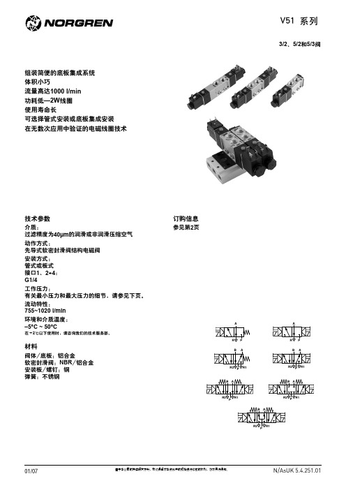
R2 P R1
01/07
基于本公司的持续研发方针,我们保留对本资料中的规格进行修改的权利,恕不另行通知。
N/AsUK 5.4.251.0
V51 系列
电磁驱动阀
符号
型号
功能
控制类型
A
V51B417A-A2*** 3/2
电控/弹簧
PR
A
V51B411A-A2*** 3/2
电控/电控
PR AB
R1 R2 P
阀位号
2 3 4 5 6 7 8 9 10
P
L
重量(kg)
57
69
0,200
80
92
0,261
103 115 0,322
126 138 0,383 149 161 0,440
172 184 0,505 195 207 0,566
218 230 0,627 241 253 0,688
C
C
17
22,5
17
3,2
6
25
2
188
25 4,2
A RP
86 18
3
35
3
8,5
G1/4
1 手控操作 2 M16 x 1,5 (进线口 4,5 to 10 mm)
基于本公司的持续研发方针,我们保留对本资料中的规格进行修改的权利,恕不另行通知。
N/AsUK 5.4.251.0
V51 系列
阀尺寸
5/2单电控电磁先导阀 机械弹簧复位
123
0,327
134 146 0,393 157 169 0,459
180 192 0,525 203 215 0,591
226 238 0,657 249 261 0,723
CTA51AO4012VDC1.9E中文资料
5
3
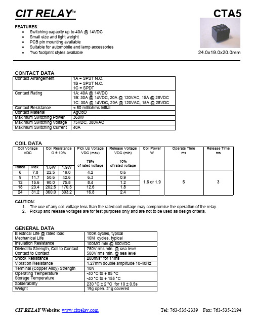
CAUTION: 1. The use of any coil voltage less than the rated coil voltage may compromise the operation of the relay. 2. Pickup and release voltages are for test purposes only and are not to be used as design criteria.
CTA5
CTA5 1A C 40 12VDC 1.6 S
ORDERING INFORMATION
DIMENSIONS: (Units = mm)
PCB Layout
Standard
European
Schematic
CIT RELAY Website:
Tel: 763-535-2339
元器件交易网
CIT RELAY™
CTA5
FEATURES: • Switching capacity up to 40A @ 14VDC • Small size and light weight • PCB pin mounting available • Suitable for automobile and lamp accessories • Two footprint styles available
24.0x19.0x20.0mm
CONTACT DATA
Contact Arrangement Contact Rating Contact Resistance Contact Material Maximum Switching Power Maximum Switching Voltage Maximum Switching Current 1A = SPST N.O. 1B = SPST N.C. 1C = SPDT 1A: 40A @ 14VDC 1B: 30A @ 14VDC, 20A @ 120VAC, 15A @ 28VDC 1C: 30A @ 14VDC, 20A @ 120VAC, 15A @ 28VDC < 50 milliohms initial AgCdO 360W 75VDC, 380VAC 40A
ATS51中文资料
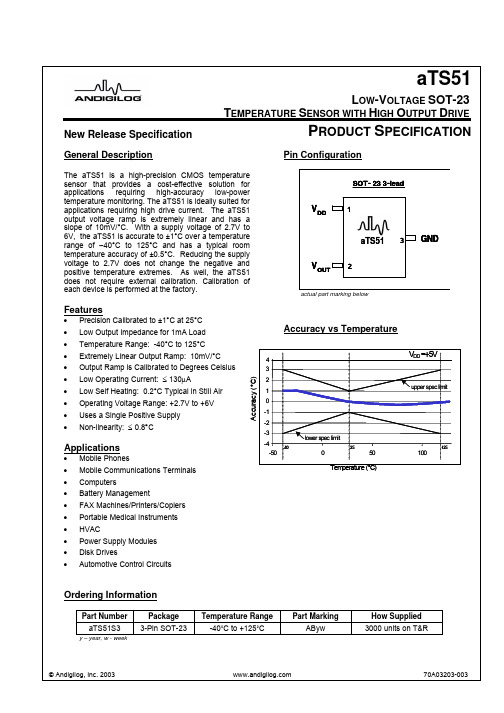
New Release SpecificationL OW -V OLTAGE SOT-23T EMPERATURE S ENSOR WITH H IGH O UTPUT D RIVEaTS51P RODUCT S PECIFICATIONGeneral DescriptionThe aTS51 is a high-precision CMOS temperature sensor that provides a cost-effective solution for applications requiring high-accuracy low-power temperature monitoring. The aTS51 is ideally suited for applications requiring high drive current. The aTS51 output voltage ramp is extremely linear and has a slope of 10mV/°C. With a supply voltage of 2.7V to 6V, the aTS51 is accurate to ±1°C over a temperature range of −40°C to 125°C and has a typical room temperature accuracy of ±0.5°C. Reducing the supply voltage to 2.7V does not change the negative and positive temperature extremes. As well, the aTS51 does not require external calibration. Calibration of each device is performed at the factory.Features• Precision Calibrated to ±1°C at 25°C • Low Output Impedance for 1mA Load • Temperature Range: -40°C to 125°C • Extremely Linear Output Ramp: 10mV/°C • Output Ramp is Calibrated to Degrees Celsius• Low Operating Current: ≤ 130μA• Low Self Heating: 0.2°C Typical in Still Air • Operating Voltage Range: +2.7V to +6V • Uses a Single Positive Supply • Non-linearity: ≤ 0.8°CApplications• Mobile Phones •Mobile Communications Terminals • Computers• Battery Management• FAX Machines/Printers/Copiers •Portable Medical Instruments • HVAC• Power Supply Modules • Disk Drives • Automotive Control CircuitsPin ConfigurationV 213SOT-23 3-leadGNDOUTV DDaTS51actual part marking belowAccuracy vs Temperature-50050100Tem perature (°C )A c c u r a c y (°C )V DD =+5Vlow er spec lim it-4-3-2-1123upper spec lim it-40251254Ordering InformationPart Number Package Temperature Range Part MarkingHow Supplied aTS51S3 3-Pin SOT-23 -40˚C to +125˚CAByw3000 units on T&Ry – year, w - weekaTS51Absolute Maximum Ratings 1Notes: 1. Absolute maximum ratings are limits beyondwhich operation may cause permanent damage tothe device. These are stress ratings only;functional operation at or above these limits is not implied.2. Human Body Model: 100pF capacitor dischargedthrough a 1.5k Ω resistor into each pin. Machine Model: 200pF capacitor discharged directly intoeach pin.3. These specifications are guaranteed only for thetest conditions listed.Recommended Operating RatingsSymbol Parameter Min Max Units V DD Supply Voltage +2.7 +6 V V OUT Output Voltage0 V DD V T AOperating Temperature Range-40+125°CElectrical Characteristics 3Limits apply for -40°C ≤T A ≤+125°C and V D D =+5.0V unless otherwise noted.Parameter Symbol Conditions Min Typ Max UnitsAccuracy 4T A =+25°CT A =-40°C (T MIN ) T A =+125°C (T MAX )-1 -3 -3±0.5 ±1 ±1+1 +3 +3°C °C °CNon-linearity 5±0.8 °C Supply Current – Output floating I DD T A =+25°C 130 μA Output Sink Capability 6I OL +2.7V < V DD < +6V 1 mA Output Source Capability 6I OH +2.7V < V DD < +6V1mAAverage Output Slope (Sensor Gain)A OUT 10 mV/°C Room Temperature Output Voltage V OUT25T A =+25°C 750 mVSelf Heating 7SOT-23 0.21840 °CNotes:4. Accuracy (expressed in °C) = Difference between calculated output voltage and measured output voltage.Calculated output voltage = 10mV/°C multiplied by device’s case temperature at specified conditions of temperature, voltage and power supply.5. Non-linearity is defined as the deviation of the output-voltage-versus-temperature curve from the best-fit straightline, over the device’s rated temperature range.6. Lowest output current should be targeted; higher currents result in more self-heating of the device.7. Max Self Heating = θJA x (V DD x I DD ). Assumes a capacitive load.Parameter RatingSupply Voltage +7VOutput Voltage V DD + 0.5V Continuous Current, any terminal 15mAStorage Temperature Range -60°C to +150°C Human Body Model 2000VESD 2 Machine Model 250VThermal Resistance - θJA 336°C/W Vapor Phase (60 sec) 215°CLead Temp Infrared (15 sec) 220°CaTS51255075100125-25-50-401750100750500V OUT (mV)Temperature (ºC)1500Temp (ºC) = (V OUT –500mV) / 10mV/ºCFigure 1. aTS51 Output Voltage vs. TemperatureMountingThe aTS51 can be easily mounted by gluing or cementing it to a surface. In this case, its temperature will be within about 0.2°C of the temperature of the surface it is attached to if the ambient air temperature is almost the same as the surface temperature. If the air temperature is much higher or lower than the surface temperature, the actual temperature of the aTS51 die will be at an intermediate temperature between the surface temperature and the air temperature.To ensure good thermal conductivity, the backside of the aTS51 die is directly attached to the GND pin. The lands and traces to the aTS51 will, of course, be part of the printed circuit board, which is the object whosetemperature is being measured. These printed circuit board lands and traces will not cause the aTS51’s temperature to deviate from the desired temperature.Alternatively, the aTS51 can be mounted inside a sealed-end metal tube, and can then be dipped into a bath or screwed into a threaded hole in a tank. As with any IC, the aTS51 and accompanying wiring and circuits must be kept insulated and dry to avoid leakage and corrosion. This is especially true if the circuit may operate at cold temperatures where condensation can occur. Printed-circuit coatings and varnishes such as Humiseal and epoxy paint or dips can be used to ensure that moisture cannot corrode the aTS51 or its connections.NOTE: When taking advantage of the high current drive capability of the aTS51 while driving resistive loads, it is necessary to apply the appropriate thermal mountingtechniques as described above. Failure to do so will result in a loss of accuracy due to increased self heating.aTS51Typical Performance Characteristics4-5050100Temperature (°C)A c c u r a c y (°C )V DD =+5Vlower spec limit-4-3-2-10123upper spec limit-4025125Figure 2. aTS51 Accuracy Range vs TemperatureI 90110120130D D ( m A )-50-25255075100125Temperature (°C)V DD = +5V10060708050403020100Figure 3. aTS51 Current vs TemperatureI D D (µA )aTS51Typical ApplicationsIN10K100K1μFFB1.75VREF 3.9KSERIAL DATA OUTCLOCKENABLEaTS515VV TempU1U2U3SerialAnalog-to-DigitalConverterAdjustable Shunt Voltage Reference+Figure 4. Serial Output Temperature to Digital Converter (Full Scale = +125˚C)5VWR5K30KINV REF1.75V15K1μF+_ PARALLEL DATA OUTPUTINTRCS RD 8V TempParallel Output Analog-to-Digital ConverteraTS51U1U3U2aTS51Typical Applications (cont.)Figure 6. Thermostat/Fan ControllerU1R14.1VR3V TempV OUT+ –R2V+ R4V+0.1μFV TU2U3aTS51 Shunt Voltage ReferenceaTS51SOT-23 Package DimensionsTape and Reel DataW 8.00 + 0.30 / -0.10 mm A 0 3.15 ± 0.10 mm B 0 2.77 ± 0.10 mm K 0 1.22 ± 0.10 mm P 0 4.00 ± 0.10 mm P 1 4.00 ± 0.10 mm P 2 2.00 ± 0.05 mm T 0.29 ± 0.13 mm 0.370 mm (min) 0.510 mm (max)1.200 mm (min) 1.400 mm (max)2.100 mm (min) 2.640 mm (max) 0.450 mm (min) 0.600 mm (max)2.800 mm (min)3.040 mm (max)0.890 mm (min) 1.120 mm (max)0.013 mm (min) 0.100 mm (max)1.780 mm (min)2.050 mm (max)0.55ref mm0.085 mm (min) 0.180 mm (max)Andigilog, Inc.7404 W. Detroit St., Suite 100 Chandler, Arizona 85226-2422 aTS51Data Sheet ClassificationsPreliminary SpecificationThis classification is shown on the heading of each page of a specification for products that are either under development(design and qualification), or in the formative planning stages. Andigilog reserves the right tochange or discontinue these products without notice.New Release SpecificationThis classification is shown on the heading of the first page only of a specification for products that are either under the later stages of development(characterization and qualification), or in the early weeks of releaseto production. Andigilog reserves the right to change the specification and information for these productswithout notice.Fully Released SpecificationFully released datasheets do not contain any classification in the first page header. These documents contain specification on products that are in full production. Andigilog will not change any guaranteed limits withoutwritten notice to the customers. Obsolete datasheets that were written prior to January 1, 2001 withoutany header classification information should be considered as obsolete and non-active specifications, or inthe best case as Preliminary Specifications.Andigilog, Inc.7404 W. Detroit St., Suite 100 Chandler, Arizona 85226-2422 aTS51Notes:。
CTA51AO3018VDC1.6E中文资料

CTA5
CTA5 1A C 40 12VDC 1.6 S
ORDERING INFORMATION
DIMENSIONS: (Units = mm)
PCB Layout
Standard
European
Schematic
CIT RELAY Website:
Tel: 763-535-2339
Rated
Max.
6 9 12 18 24
7.8 11.7 15.6 23.4 31.2
1.6W 22.5 50.6 90.0 202.5 360.0
1.9W 19.0 42.6 75.8 170.5 303.2
4.2 6.3 8.4 12.6 16.8
0.6 0.9 1.2 1.8 2.4
1.6 or 1.9
COIL DATA
Coil Voltage VDC Coil Resistance Ω ± 10% Pick Up Voltage VDC (max) 75% of rated voltage Release Voltage VDC (min) 10% of rated voltage Coil Power W Operate Time ms Release Time ms
Fax: 763-535-2194
GENERAL DATA
Electrical Life @ rated load Mechanical Life Insulation Resistance Dielectric Strength, Coil to Contact Contact to Contact Shock Resistance Vibration Resistance Terminal (Copper Alloy) Strength Operating Temperature Storage Temperature Solderability Weight 100K cycles, typical 10M cycles, typical 100MΩ min @ 500VDC 750V rms min. @ sea level 500V rms min. @ sea level 200m/s2 for 11ms 1.27mm double amplitude 10-40Hz 10N -40 °C to + 85 °C -40 °C to + 155 °C 230 °C ± 2 °C for 10 ± 0.5s 19g open. 21g covered
ml51eb9ae规格书

ml51eb9ae规格书如下:* 型号:ml51eb9ae* 适用范围:ml51eb9ae是一款高性能的微型马达,适用于各种需要微小动力输出的场合。
* 外观尺寸:ml51eb9ae的外观尺寸为φ5.5mm×1.4mm,非常小巧。
* 安装方式:ml51eb9ae可以安装在各种需要微小动力输出的设备中,如传感器、控制器等。
* 工作电压:ml51eb9ae的工作电压范围为2.4V-3.6V,适合电池供电。
* 工作温度:-20℃~85℃* 重量:ml51eb9ae的重量非常轻,只有3g左右。
* 最大转速:ml51eb9ae的最大转速为2500转/分。
* 静音性能:ml51eb9ae在额定电压下工作,噪音非常小,可以适应各种环境。
* 最大扭矩:ml51eb9ae的最大扭矩为0.2mN·m。
* 持续工作时间:在额定电压下,ml51eb9ae可以持续工作数分钟到数十分钟,具体取决于应用场合和负载大小。
* 工作模式:ml51eb9ae是一款有刷直流马达,采用机械换向器来实现有规律的通电变化,从而达到旋转运动的目的。
* 防护等级:ml51eb9ae的防护等级为IP20,可以在一般环境下工作,但需要注意防尘。
* 特点:ml51eb9ae具有体积小、重量轻、噪音小、持续工作时间长等特点,适用于各种需要微小动力输出的场合。
总的来说,ml51eb9ae是一款高性能的微型马达,具有体积小、重量轻、噪音小、持续工作时间长等特点,适用于各种需要微小动力输出的场合。
其最大转速为2500转/分,最大扭矩为0.2mN·m,可以在-20℃~85℃的环境下工作。
此外,它还具有安装方式灵活、工作电压低、噪音小、防护等级高等优点,可以适应各种环境。
因此,ml51eb9ae是一款非常适合各种微小动力输出场合应用的马达。
R12C09中文资料
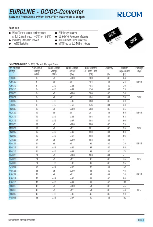
FeaturesElectrical Specifications (measured at T A = 25°C,at nominal input voltage and rated output current unless otherwise specified)Input Voltage Range V IN (continuous operation)5V types 4.5VDC min./ 5.5VDC max.12V types 10.8VDC min./ 13.2VDC max.24V types 21.6VDC min./ 26.4VDC max.48V types43.2VDC min./ 52.8VDC max.Reflected Ripple Current (depending on the type)50 mA p-p min.to 200 mA p-p max.Output Voltage Accuracy (depending on the type)–5% min./ 7.5% max.Line Regulation (highV IN to low V IN )1.0% min./ 1.2% max.of V INLoad Regulation (10% load to rated load) (depending on the type)3% typ./ 10% max.Ripple and Noise (BW=DC to 20MHz) (depending on the type)70mVp-p min./ 200mVp-p max.Isolation Voltage (flash tested for 1 second)1000VDC min.Test Voltage (50Hz,10 seconds)1000 Vpk min.Resistance (Viso = 500V)1G Ωmin./ 10 G Ωtyp.Switching Frequency at Full Load (depending on the type)80kHz min./ 95kHz max.Package Weight SIP types 2.76 g DIP types2.85 g Efficiency (100% load)70% min.Power Consumption (0% load)300mW typ.Operating Temperature Range (all output types)–40°C min.to +85°C max.(see graph)Storage Temperature Range–50°C to +130°C Case Temperature Above Ambient (depending on the type)+25°C min./ +30°C max.MTTF 2) (depending on the type))–40°C 134kHrs min./ 2004kHrs max.+25°C 112kHrs min./ 1574kHrs max.+85°C93kHrs min./ 1101kHrs max.2).Calculated using MIL-HDBK-217F with nominal input voltage at full load.Please contact us,if you need exact parameters for the converter you have selected.Absolute Maximum RatingsInput Voltage V IN05V types 7VDC 12V types 15VDC 24V types 28VDC 48V types54VDC Short Circuit Duration 1) 1 s Internal Power Dissipation300mW Lead Temperature (1.5mm from case for 10 seconds)300°C1).Supply voltage must be discontinued at the end of the short circuit duration.Typical Characteristics,Tolerance Envelope and Derating Graph。
A1E 系列交流伺服驱动器 用户手册说明书

基本规格 ........................................................................................................................................... 4
速度、位置、转矩控制规格 ........................................................................................................... 5
1
1.1
1.2
1.3
1.4
1.5
2
2.1
2.2
2.2.1
2.2.2
2.3
2.4
2.5
3
3.1
3.2
3.3
4
4.1
4.2
4.3
4.4
4.5
4.5.1
4.5.2
4.5.3
5
安全提醒 ................................................................................................................................................... 1
CTA1中文资料
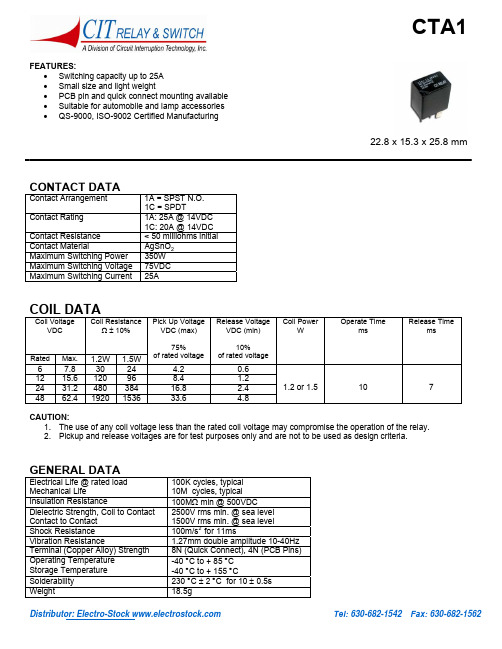
Distributor: Electro-Stock Tel: 630-682-1542 Fax: 630-682-1562FEATURES:• Switching capacity up to 25A • Small size and light weight• PCB pin and quick connect mounting available • Suitable for automobile and lamp accessories • QS-9000, ISO-9002 Certified Manufacturing22.8 x 15.3 x 25.8 mmCONTACT DATAContact Arrangement 1A = SPST N.O. 1C = SPDTContact Rating1A: 25A @ 14VDC 1C: 20A @ 14VDC Contact Resistance < 50 milliohms initial Contact MaterialAgSnO 2 Maximum Switching Power 350W Maximum Switching Voltage 75VDC Maximum Switching Current25ACOIL DATACoil VoltageVDCCoil ResistanceΩ ± 10%Rated Max. 1.2W 1.5W Pick Up Voltage VDC (max)75%of rated voltage Release Voltage VDC (min)10%of rated voltageCoil PowerWOperate TimemsRelease Timems6 7.8 30 24 4.20.6 12 15.6 120 96 8.41.2 24 31.2 480 384 16.82.4 48 62.4 1920 1536 33.64.81.2 or 1.5 10 7CAUTION:1. The use of any coil voltage less than the rated coil voltage may compromise the operation of the relay.2. Pickup and release voltages are for test purposes only and are not to be used as design criteria.GENERAL DATAElectrical Life @ rated load Mechanical Life 100K cycles, typical 10M cycles, typical Insulation Resistance 100M Ω min @ 500VDCDielectric Strength, Coil to Contact Contact to Contact 2500V rms min. @ sea level 1500V rms min. @ sea level Shock Resistance 100m/s 2 for 11ms Vibration Resistance 1.27mm double amplitude 10-40Hz Terminal (Copper Alloy) Strength 8N (Quick Connect), 4N (PCB Pins) Operating Temperature Storage Temperature -40 °C to + 85 °C -40 °C to + 155 °C Solderability 230 °C ± 2 °C for 10 ± 0.5sWeight 18.5gDistributor: Electro-Stock Tel: 630-682-1542 Fax: 630-682-1562ORDERING INFORMATION1. Series:CTA1CTA12.Contact Arrangement: 1A=SPST N.O. 1C=SPDT1A3. Sealing Options: S = Sealed C = Dust Cover S4. Termination: P = PCB PinsQ = Quick Connect Q5. Coil Voltage: 6VDC 12VDC 24VDC 48VDC126. Coil Power: 1.2 = 1.2W 1.5 = 1.5W1.27. Coil Suppression: Blank = Standard D = Diode (1N4005)R = Resistor (680 Ohms)** Consult factory if other values are needed.DIMENSIONS (Units = mm) PC PIN DIMENSIONS (Units = mm)SCHEMATICS & PC LAYOUT (BOTTOM VIEWS)1A 1C。
NT90TNLAEDC12VI中文资料

3 5 6 9 12 15 18 24 48 110
3.9 6.5 7.8 11.7 15.6 19.5 23.4 31.2 62.4 143
15 42 60 135 240 375 540 960 3840 20167
2.25 3.75 4.50 6.75 9.00 10.25 13.50 18.00 36.00 82.50
Dimensions
0.130 0.020 (0.146) 0.787max.
mm /inch
0.020
20max.
24.2max. 0.953max.
3.3 0.130
17max. 0.669max.
0.031 0.059 0.027 0.027 0.047 0.047
0.492
2.4 0.094 0.209
Qualification inspection:
Perform the qualification test as specified in the table of IEC255-19-1 and minimum sample size 24.
121
元器件交易网
NHG RELAYS
Dash numbers
Coil resistance 10%
Coil power W
Operate Time ms
Release Time ms
10 28 40 90 160 250 360 640 2560 13445
0.9
15
10
003-600 005-600 006-600 009-600 012-600 015-600 018-600 024-600 048-600 110-600
ED9901A中文说明书

1.产品主要技术指标12.产品出厂缺省值3.声光显示3.1.正常工作状态下:3.1.1.有效指令:嘟短声3.1.2.无效指令:嘟长声3.2.编程状态下:3.2.1.绿灯常亮3.2.2.有效指令:嘟嘟两声3.2.3.无效指令:嘟嘟嘟三声4.撤销未完成的指令:在键入指令没有全部完成前,按下[*]键,可以撤销该项指令25.功能及设置5.1.进入编程:[*]+[6位编程密码]嘟嘟,缺省:990101 5.2.修改编程密码:[0]+[输入6位新编程密码]+[重复输入6位新编程密码]5.3.设置有效卡:[5]+[输入3位编码]嘟嘟+[感应卡1]嘟、嘟嘟+[感应卡2]嘟、嘟嘟+……+[感应卡n]嘟、嘟嘟+[*]嘟嘟,完成加卡5.3.1.3位编码:是001——500之间不可重复数字。
该编码是在卡丢失后删除卡的重要方式,请发卡人员妥善保存卡编码5.3.2.连续设置有效卡时,每张卡的编码按前一张卡的编码+1递增。
例如输入编码为015,再次读卡时,再次卡的编码为016……依次类推5.3.3.有效卡缺省个人密码:000035.4.删除有效卡:5.4.1.编码方式删卡:[7]+[输入3位编码1]嘟嘟+[输入3位编码2]嘟嘟+……+[输入3位编码n]嘟嘟+[*]嘟嘟,完成删卡5.4.2.感应方式删卡:[7]+[感应卡1]嘟、嘟嘟+[感应卡2]嘟、嘟嘟+……+[感应卡n]嘟、嘟嘟+[*]嘟嘟完成删卡5.4.3.删除所有已设置卡:请使用恢复出厂设置的方式5.4.4.删除有效卡后其个人密码也一并删除5.5.退出编程状态:[*]嘟嘟5.6.设置感应卡的开门方式:5.6.1.卡或密码方式:[1]+[0]嘟嘟(缺省)5.6.2.卡+个人密码方式:[1]+[1]嘟嘟45.7.密码5.7.1.“卡或密码”方式中的密码:是指每张有效卡内的个人密码(最多500个个人密码),以及1个通用密码5.7.2.关闭修改个人密码功能:[1]+[2]嘟嘟(缺省)5.7.3.开启修改个人密码功能:[1]+[3]嘟嘟5.7.4.修改个人密码:非编程状态下[#]嘟嘟+[读感应卡]嘟、嘟嘟+[输入4位原密码](缺省0000)嘟嘟+[输入4位新密码]+[重复输入4位新密码]嘟嘟;5.7.5.修改通用密码:[3]+[4位通用密码](缺省1234)当通用密码或者个人密码为0000时,在“卡或密码”方式下,密码无效5.8.设置开锁时间:[2]+[TT]。
ml51fb9ae规格书

ml51fb9ae规格书ML51FB9AE是一款高性能的微控制器芯片,广泛应用于各种嵌入式系统中。
本文将详细介绍ML51FB9AE的规格和特性,以及其在不同领域中的应用。
ML51FB9AE是一款基于ARM Cortex-M0架构的32位微控制器。
它具有高性能、低功耗、易扩展等特点,适用于多种应用场景。
该芯片的主要规格如下:1. 处理器和内存:ML51FB9AE搭载了一颗高性能的ARM Cortex-M0处理器,最高主频可达XX MHz。
它配备了XX KB的Flash存储器和XX KB的RAM,能够满足大多数应用的需求。
同时,它支持片上和外部存储器扩展,可以根据实际需求进行灵活配置。
2. 通信接口:ML51FB9AE支持多种通信接口,包括UART、SPI、I2C和USB等。
这些接口能够与外部设备进行可靠的数据传输,实现与其他模块的通信。
此外,ML51FB9AE还提供了多个GPIO引脚,可以方便地与外部设备进行连接。
3. 定时器和计数器:ML51FB9AE拥有多个定时器和计数器,可用于测量时间、产生高精度的时钟信号和触发事件。
其中,包括通用定时器、看门狗定时器和RTC等,用户可以根据实际需求进行配置和使用。
4. 电源管理:ML51FB9AE具备优秀的电源管理特性,包括多种低功耗模式、快速唤醒功能和多电源域分离等。
这些特性可以最大程度地降低功耗,延长电池寿命,适用于移动设备和依赖电池供电的应用。
ML51FB9AE作为一款高性能的微控制器芯片,广泛应用于各种嵌入式系统中。
下面是一些典型应用领域的介绍:1. 工业自动化:ML51FB9AE具有强大的计算能力和丰富的通信接口,可以广泛应用于工业自动化领域。
它可以实现设备之间的高速数据传输和协同控制,提高系统效率和稳定性。
2. 智能家居:由于其低功耗和高性能特点,ML51FB9AE非常适合用于智能家居领域。
它可以与各种传感器和执行器配合使用,实现智能控制、远程监控和自动化管理等功能。
戴尔专业音棒AE515用户指南说明书

Dell Professional Sound Bar AE515User’s GuideRegulatory model: AE515Notes, cautions, and warningsNOTE: A NOTE indicates important information thathelps you make better use of your computer.CAUTION: A CAUTION indicates either potentialdamage to hardware or loss of data and tells you howto avoid the problemWARNING: A WARNING indicates a potential forproperty damage, personal injury, or death.Copyright © 2017 Dell Inc. All rights reserved. This product is protected by U.S. and international copyright and intellectual property laws. Dell™ and the Dell logo are trademarks of Dell Inc. in the United States and/or other jurisdictions. All other marks and names mentioned herein may be trademarks of their respective companies.2017 - 01Rev. A00ContentsWhat’s in the box (4)Features (5)Setting up your speaker (6)Installing the Sound bar to your Dell monitor (6)Powering on your speaker (7)Connecting your speaker (8)Audio-in port (8)Answering Skype for Business calls (10)Making Skype for Business calls (11)Adjusting the volume (12)Troubleshooting (13)Specifications (17)Statutory information (18)Warranty (18)3What’s in the boxNOTE: The documents that shipped with the speakermay vary based on your region.1 Audio cable2 USB cable3 Documents4 Sound bar12344Features1 Call pick up 6 Aux-in2 Microphone 7 Volume down3 Call hang up 8Microphone4 Default Playbackbutton 9 Volume up5 H eadphone10Mic mute1 2 35Setting up your speaker Installing the Sound bar to your Dell monitor1Hold the sound bar and push the hook into the monitor slot.2Slide the sound bar to the right to engage the hook into the monitor slot.6Powering on your speakerNOTE:If the sound bar is not detected, connect the uplink cable thatcame with your Dell monitor. Connect one end of the uplink cable to theUSB port on the Dell monitor and the other end to the USB port on yourDell computer.1Plug the USB cable connected to the sound bar into the USB port of the Dell Monitor.2The sound bar will automatically power on once the system is powered up.The light on the right of the sound bar turns solid white.7Connecting your speakerUse the audio in or aux-in jack to connect your audio device (tablet, smart phone) to your Dell sound bar.Audio-in portYou can play audio using the audio-in cable that came with your speaker.1Connect the audio-in cable to the aux-in port on the left sound bar.2Connect the other end of the audio-in cable to your audio device.3Play music and adjust the volume as desired.NOTE:When audio in is the default playback device, the light on themicrophone button turns solid red. The sound bar microphone cannotbe used in this playback mode.8Headphone jack1Connect the headphone to the headphone jack on the sound bar.2Play music and adjust the volume as desired.3Press the Default playback button on the left side of the sound bar to toggle between the speaker and headphone.NOTE:The Default playback button is disabled when the headphone isnot connected to the sound bar.Answering Skype for Business calls1Press the call button.NOTE: The light indicator on Call pick-up button slow blinks when thereis an incoming call on Skype for Business and other supported software. 2Press the call hang-up button to end the call.3Press the mic mute button to mute the microphone on the sound bar.Pressing the mic mute button again will unmute the microphone on the sound bar.Answering a callMuting the micHang-up the call10Making Skype for Business calls 1Press the call button to open up Skype for Business.2Initiate a call via the Skype for Business application on your computer.3Press the call hang-up button to end the call.4Press the mic mute button to mute the microphone on the sound bar.Pressing the mic mute button again will unmute the microphone on the sound bar.Making a callMuting the micHang-up the callAdjusting the volume1Press the + button to turn the volume up. A soft dual tone can be heard when the speaker is at the maximum volume.2 Press the - button to turn the volume down. A soft single tone can be heardwhen the speaker is at the minimum volume.12Volume upVolume downTroubleshootingProblems Possible causes Possible solutionsNo sound No sound from theexternal audiosource •Check if the 3.5 mm aux-in cable is inserted in thespeaker aux-in port. •Unplug the 3.5 mm aux-in cable from the aux-in jackand insert the cable again. •Check if the audio source is powered on.•Make sure that the audio device volume is not set to0%.•Try a known good speaker or audio source.Abnormal sound Distorted or buzzingsound •Clear any obstructionsbetween the sound bar andthe user.•In aux-in mode, ensure that the 3.5 mm plug iscompletely inserted on theaux-in port of the soundcard.•Decrease the volume of the audio application or musicplayer.•Turn the volume level tolower setting by pressing the- button on the sound bar. •Test the speaker usinganother audio source (forexample, a portable CDplayer or an MP3 player).Unbalanced sound output Sound is comingfrom only one sideof the sound bar•Clear any obstructionsbetween the sound bar andthe user.•In aux-in mode, ensure thatthe 3.5 mm plug iscompletely inserted in theaux-in port of the sound baror audio source.•Set the Windows audiobalance controls for left andright speaker.•Clean and reseat all cables.•Test the sound bar usinganother audio source (forexample, a portable CDplayer or an MP3 player).Low volume Volume is too low •Clear any obstructionsbetween the sound bar andthe user.•Turn the volume to a higherlevel by pressing the +button on the sound bar.•Set all Windows volumecontrols to their maximum.•Increase the volume of theaudio application.•Test the sound bar usinganother audio source (forexample, a portable CDplayer or an MP3 player).Aux-in no sound No sound using theaux-in mode •Make sure that the aux-in cable is properly plugged inthe sound bar aux-in port andto the aux-out jack of theaudio device.14•Try a known good aux-incable.•Check if the audio device is powered on or is playingmusic.•Make sure that the audio device volume is not set to0%.•Try a known good speaker or audio source.Aux-in distortion Aux-in cable is notproperly plugged in •Clear any obstructionsbetween the sound bar andthe user.•Ensure that the aux-in plug is completely inserted into theaux-out port of the audiosource.•Decrease the volume of the audio source.•Turn the volume level to a lower setting by pressing the- button on the sound bar. •Clean and reseat the cables. •Make sure no loose objects are touching the sound bar.Headphone jack is connected, but no sound is heard Computer audioplayer is playing•Make sure that the platformmusic player audio volume isnot set to 0%•Increase the volume of thesound bar.•Press the default playbackfunction button on the soundbar.Headphone abnormal sound Audio distortion •Check if the headphone plugis properly inserted into thespeaker headphone jack.•Check if the headphone plughas intermittent connection.•Check if the music file is notdistorted when playingwithout the headphone orconnected to a known goodheadphone.16SpecificationsGeneralModel number AE515 Connection type USB cableAudio cable ElectricalOperating voltage 5 V Operating current 500 mAAudio Input Audio InputAnalog Audio Aux-in (3.5mm jack)Output Power 2 x 1.8W @ ≤10% THD (USB3.0)2 x 1.0W @ ≤10% THD (USB2.0)SPL 84dB ±3dBPhysical CharacteristicsSound bar dimensions:Width 443 mm (17.441 in)Height 35 mm (1.378 in)Depth 60.43 mm (2.379 in)Weight 440 g (0.97 lb)17Statutory informationWarrantyLimited warranty and return policiesDell-branded products carry a 1-year limited hardware warranty. If purchased together with a Dell system, it will follow the system warranty.For U.S. customers:This purchase and your use of this product are subject to Dell’s end user agreement, which you can find at /terms. This document contains a binding arbitration clause.For European, Middle Eastern and African customers:Dell-branded products that are sold and used are subject to applicable national consumer legal rights, the terms of any retailer sale agreement that you have entered into (which will apply between you and the retailer) and Dell’s end user contract terms.Dell may also provide an additional hardware warranty—full details of the Dell end user contract and warranty terms can be found by going to , selecting your country from the list at the bottom of the “home” page and then clicking the “terms and conditions” link for the end user terms or the “support” link for the warranty terms.For non-U.S. customers:Dell-branded products that are sold and used are subject to applicable national consumer legal rights, the terms of any retailer sale agreement that you have entered into (which will apply between you and the retailer) and Dell’s warranty terms. Dell may also provide an additional hardware warranty—full details of Dell’s warranty terms can be found by going to , selecting your country from the list at the bottom of the “home” page and then clicking the “terms and conditions” link or the “support” link for the warranty terms.18。
AE__DC电源说明书_汉化版

PAGE 5客户反馈对此说明书的格式或内容有任何意见都可以发送邮件至:要订购一份说明书,请联系技术支持:PAGE 7目录第一章. 安全与产品兼容性指导重要安全信息……1-1说明书中的危险,警告,和注意提示框……1-2安全指导……1-2安全安装与运作的规则……1-2产品标签解释……1-3产品兼容性……1-5产品证书……1-5安全和EMC 标示与标准……1-6电磁兼容性(EMC)标示与标准……1-6安全标示与标准……1-7工业指导……1-7使用的条件……1-7第二章. 操作原理整体说明……2-1输出阻抗的范围……2-1输出调节……2-1接口……2-1微处理器的优点……2-2显示……2-2抑弧特性……2-2运作原理……2-2输入……2-3家务管理式供应……2-3转向器……2-3输出……2-3输出范围……2-3逻辑控制……2-4远程接口……2-4第三章. 产品规格功能规格……3-1物理规格……3-3尺寸工程图……3-5电气规格……3-6环境规格……3-12冷却规格……3-13PAGE 8第四章. 通信接口用户接口……4-1连接器……4-1信号……4-3模拟信号……4-3数字信号……4-3引脚说明……4-3接触器互锁端口……4-10接触器互锁端口连接器……4-10接触器互锁线缆要求……4-11接触器互锁端口引脚描述……4-12被动显示面板……4-14显示……4-14LEDs……4-15主动前面板/Pinnacle 远程面板……4-16连接到远程主动面板……4-16面板的理解……4-18控制按键……4-18输出显示画面……4-18软键……4-18修改旋钮……4-19调节按钮……4-19开关按钮和LED指示灯……4-19放电LED指示灯……4-19控制面板界面……4-19输出功率按钮……4-20控制按钮……4-20调节按钮……4-21双线输出显示画面……4-21软键……4-22修改旋钮……4-22控制面板的控制……4-22菜单选项的理解……4-23使用服务功能……4-25确认服务类型错误……4-26确认服务类型统计……4-26确认总能量输出……4-26确认总的空闲时间……4-26确认错误的数量……4-26确认循环的数量……4-27检查你的装置……4-27观察从属装置的地址……4-27确认你的错误主/从系统……4-28确认你的硬件结构……4-28确认你的软件逻辑……4-29PAGE 9确认你的ROM……4-29确认你的软件版本……4-29使用供应功能……4-29设定AE总线的终止时间……4-30设定供应参数……4-30设定面板模式……4-30选择远程或者本地模式…4-30选择一个上锁编码……4-31选择Clicks的数量……4-31设定程序源……4-31使用进程功能……4-32监视你的进程……4-32设定并观察主/从系统诊断建立一个最小的进程电压……4-34设定一个超出设定点的计时器……4-34修改靶材功能……4-35设定进程极限……4-36设定一个电压跳脱的极限…… 4-37设定一个输出电压的最大极限……4-38设定一个输出电流的最大极限……4-38设定一个输出功率的最大极限……4-38设定放电的处理……4-39设定放电电压的Trip水平……4-39设定放电特征……4-39设定放电计数极限……4-40观察放电密度……4-40修改放电密度窗口的长度……4-41设定放电统计持续期间窗口……4-41设定放电的次数……4-42预定义放电处理……4-42启用放电处理……4-43设定控制参数……4-44设定处方……4-44设定波动水平……4-45使用靶材条件循环(TCC)……4-46启用靶材条件循环(TCC)……4-46设定靶材条件循环(TCC)计时器……4-46设定焦耳模式……4-47设定焦耳设定点……4-47设定焦耳起始点……4-47设定上升坡度……4-48标准系列(闪存)端口……4-49标准系列端口描述……4-49传送参数……4-50AE总线(主)端口……4-50AE总线(主)连接器和引脚描述……4-51 AE总线传送参数……4-51PAGE 10设定装置的网络地址……4-52按钮的类型和设置……4-52外部DIPs……4-54内部DIPs……4-55最小开关……4-56可能的网络地址的按键设定……4-57设定Baud速率和通信模式……4-58AE总线(主)通信……4-59AE总线协议……4-59AE总线头字节……4-59AE总线命令数字字节……4-60AE总线选项长度字节……4-60AE总线数据字节……4-60AE总线检查加总字节……4-61创建一个理想的通信交易…4-62T0:主传送信息包……4-62T1:单元核实主传送包……4-62T2:单元传送到主机的响应……4-63T3:主机获得响应单元……4-63AE总线通信交易实例……4-64AE总线命令……4-64AE总线命令状态响应(CSR)代码……4-64 AE总线命令设定……4-66命令序列事例……4-108单元解说……4-111第五章. 安装,建立,和运作装置的安装前准备……5-1安装空间需求……5-1冷却需求……5-1陈列柜涉及……5-2安装需求……5-6打开装置的包装……5-6装置的安装……5-6接地……5-7连接接触器Intlk端口……5-8连接一个远程被动面板……5-9连接一个Pinnacle远程主动面板……5-9连接到标准系列端口……5-9连接系列(主)端口控制……5-9连接用户端口控制……5-10连接输入电源……5-10输入电源线缆需求……5-14 Ring-Lug输入连接器……5-105 终端输入连接器……5-12连接输出电源……5-13PAGE 11三终端,多接触可插入式连接器(标准)……5-13连接放电连接性能…….5-23连接主/从运作……5-24主从运作的理解…….5-24主/从主卡接口……5-24构建一个主/从系统……5-25主/从结构事例……5-27后部面板图纸……5-2装置的运作……5-29普通运作……5-29放电处理的理解……5-31电压放电(V-Arc)的跳脱水平……5-32TCC算法启用……5-32靶材类型:金属……5-33靶材类型:非金属……5-33靶材类型:Custom…….5-33放电检测延迟时间……5-34放电关闭时间……5-36放电极限响应……5-38放电链接运作……5-39Pinnacle总线错误的理解……5-39总线错误的类型……5-39如果10毫秒总线错误连续地发生……5-39主/从系统运作……5-40主/从输入开/关结合……5-41监视主/从系统……5-43清除主/从系统中的错误……5-43第六章. 故障处理和全球服务在打电话给AE全球服务之前……6-1首先确认……6-1确认电源关……6-1确认电源开……6-1确认如果输出不开启……6-3帮助代码问题解决表……6-4被动显示面板代码……6-6LED故障处理表……6-7清除错误代码……6-8错误代码故障处理表……6-8主/从错误向量从状态高字节……6-22从状态低字节……6-22个人卡状态……6-23联系AE全球服务……6-24先进能量世界总部,24*7技术支持……6-24及其返修……6-24PAGE 13图片清单……PAGE 15表格清单……PAGE 25总体描述AE 系列直流电源提供了直流电源方面最大的优势。
AWZ 05122 12VDC线性电源供电单元说明书

Dimensions Net/gross weight Closing Notes
230V AC 50Hz 0,29A 24W max. 12V DC 5x 0,4A for F 500mA fuses Ic= 2A max (total, continuous) @12V DC 11V÷15V DC 5x F 500mA fuse (damage requires fuse-element replacement or PTC 500mA – jumper selectable. 110% ÷ 150% (@25ºC) of PSU power - current limiting by the PTC resettable fuse, manual restart (failure demands cutting off the DC output circuit) U>17V (-/+ 5%) disconnection of the output voltage, automatic return varistors electronic - a microswitch, NC contacts (enclosure closed) 0,5A@50V DC (max.)
爱欧迪i9简体中文说明书

+ 目录
设置模式
36
JetEffect 3.0
显示屏
时间
音乐
视频
录制
系统
补充说明
42
产品规范
使用 COWON MediaCenter - JetAudio 转换视频文件
故障排除
48
用前须知!
+ 注意事项
对于由于用户错误使用产品及不遵守本手册中说明的原则/指南而对产品造成的 任何损坏或失效,COWON 不承担任何责任。
iAUDIO 9
11
用前须知!
+ 连接和断开连接 PC
1
2
PC
6. 单击弹出消息。 7. 安全地删除硬件并拔下 USB 电缆。
PC
3
4 DRAG
1. 使用 USB 电缆将 iAUDIO 9 连接到计算机。
2. 如是正确连接到计算机,iAUDIO 9 会显示以下图像(图 2)。
3. 请务必检查“我的电脑”或“Windows 资源管理器”,查看
6
iAUDIO 9
用前须知!
+ 注意事项
+ 为了保护您起见,请在光线明亮的地方使用播放器,这样 LCD 屏幕不会过度损伤您的眼 + 在存在很多静电的地方使用播放器可能会导致故障。 + 如果主要将此设备用作存储设备,建议在使用之前备份所有数据。 COWON SYSTEMS Inc. 对于由于硬件故障造成的任何数
将选中的文件添加到收藏夹。
1
* 可以从收藏夹列表中检查添加的文件,并且可以重复添加相同的文件。
5
删除实际的文件或书签列表。
3
4
* 删除书签列表并不会删除实际的文件。只能在 [文件夹] 模式下删除实际的
APWR51E简要介绍
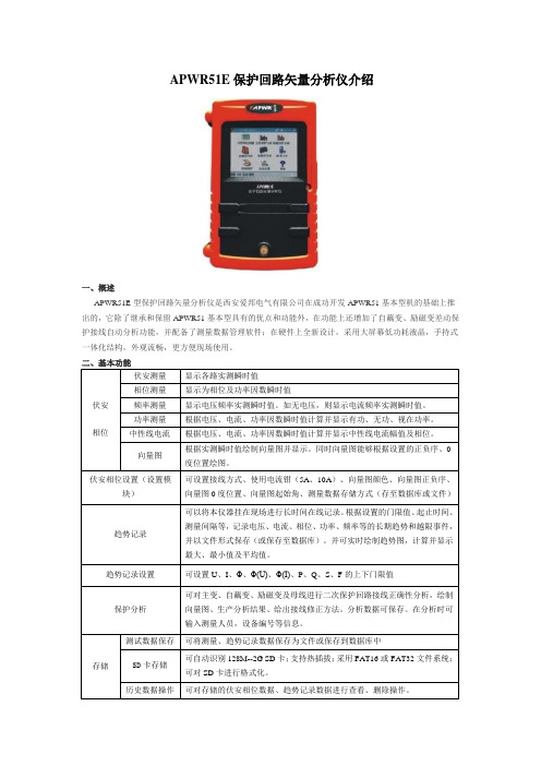
APWR51E保护回路矢量分析仪介绍一、概述APWR51E型保护回路矢量分析仪是西安爱邦电气有限公司在成功开发APWR51基本型机的基础上推出的,它除了继承和保留APWR51基本型具有的优点和功能外,在功能上还增加了自藕变、励磁变差动保护接线自动分析功能,并配备了测量数据管理软件;在硬件上全新设计,采用大屏幕低功耗液晶,手持式一体化结构,外观流畅,更方便现场使用。
三、PC软件功能四、主要技术指标◆电压测量范围:5V~500V;分辨率0.01V;精度:0.1%×量程。
◆电流标配电流钳:10mA~10A;选配电流钳:1mA~5A;分辨率:0.001A;精度0.1%×量程。
◆相位测量范围:0~360°;分辨率:0.1°;误差±2°。
◆频率测量:40~60Hz;分辨率:0.01 Hz;精度:0.1%×读数。
◆功率有功:0.05~5000;分辨率:0.1;误差:0.2%×读数(PF=1);无功:0.05~5000;分辨率:0.1;误差:0.2%×读数(PF=0);视在:0.05~5000;分辨率:0.1;误差:0.2%×读数。
◆电源3节5号干电池供电,续航能力超过15小时(在不开背光时);也可交流电供电(100~240V),交流适配器输入。
五、出厂配置◆APWR51E型主机1台◆PC软件光盘1张◆1mA~5A高灵敏度电流钳3把◆10A电流钳3把◆电压测试线4条◆电压鳄鱼夹4只◆交流电源适配器1只◆电源线1条◆SD卡1只(1G容量)◆使用说明书1本◆合格证1份◆铝合金便携箱一个。
- 1、下载文档前请自行甄别文档内容的完整性,平台不提供额外的编辑、内容补充、找答案等附加服务。
- 2、"仅部分预览"的文档,不可在线预览部分如存在完整性等问题,可反馈申请退款(可完整预览的文档不适用该条件!)。
- 3、如文档侵犯您的权益,请联系客服反馈,我们会尽快为您处理(人工客服工作时间:9:00-18:30)。
Distributor: Electro-Stock Tel: 630-682-1542 Fax: 630-682-1562 FEATURES:
• Switching capacity up to 40A @ 14VDC • Small size and light weight • PCB pin mounting available
• Suitable for automobile and lamp accessories
• Two footprint styles available
25.8 X 20.5 X 20.8mm
CONTACT DATA
Contact Arrangement 1A = SPST N.O. 1B = SPST N.C. 1C = SPDT
Contact Rating
1A: 40A @ 14VDC, 20A @ 120VAC, 15A @ 28VDC 1B: 30A @ 14VDC, 20A @ 120VAC, 15A @ 28VDC 1C: 30A @ 14VDC, 20A @ 120VAC, 15A @ 28VDC Contact Resistance < 50 milliohms initial Contact Material
AgSnO 2 Maximum Switching Power 360W
Maximum Switching Voltage 75VDC, 380VAC Maximum Switching Current 40A
COIL DATA
Coil Voltage
VDC
Coil Resistance
Ω ± 10%
Rated Max. 1.6W 1.9W Pick Up Voltage VDC (max)
75%
of rated voltage Release Voltage VDC (min)
10%
of rated voltage
Coil Power
W
Operate Time
ms
Release Time
ms
6 7.8 22.5 19.0 4.2
0.6 9 11.7 50.6 42.6 6.3
0.9 12 15.6 90.0 75.8 8.4 1.2 18 23.4 202.5 170.5 12.6 1.8 24 31.2 360.0 303.2 16.8 2.4
1.6 or 1.9 5 3
CAUTION:
1. The use of any coil voltage less than the rated coil voltage may compromise the operation of the relay.
2. Pickup and release voltages are for test purposes only and are not to be used as design criteria.
GENERAL DATA
Electrical Life @ rated load Mechanical Life
100K cycles, typical 10M cycles, typical Insulation Resistance
100M Ω min @ 500VDC Dielectric Strength, Coil to Contact Contact to Contact 750V rms min. @ sea level 500V rms min. @ sea level Shock Resistance 200m/s 2 for 11ms
Vibration Resistance
1.27mm double amplitude 10-40Hz Terminal (Copper Alloy) Strength 10N
Operating Temperature Storage Temperature -40 °C to + 85 °C -40 °C to + 155 °C
Solderability 230 °C ± 2 °C for 10 ± 0.5s Weight
19g open. 21g covered
Distributor: Electro-Stock Tel: 630-682-1542 Fax: 630-682-1562
ORDERING INFORMATION
1. Series: CTA5
CTA5 2.Contact Arrangement:
1A = SPST N.O. 1B = SPST N.C. 1C = SPDT
1A
3. Sealing Options:
O = Open Frame
S = Sealed (standard PC layout) E = Sealed (European PC layout) C = Dust Cover
C 4. Coil Voltage: 6VDC 9VDC 12VDC 18VDC 24VDC
12VDC
6. Coil Power: 1.6 = 1.6W 1.9 = 1.9W
1.6
DIMENSIONS (Units = mm)
SCHEMATICS & PC LAYOUTS (BOTTOM VIEWS)
OPEN FRAME SEALED
1A 1B 1C 1A 1B 1C
S = Standard
E = European。
