HIP0060ABZ中文资料
EBDW020A0B641-PHZ中文资料(Lineage Power)中文数据手册「EasyDatasheet - 矽搜」

All : All
V t V t
¾
__ __ __
750 800 750 800
¾
__
¾
mV
ms
__
mV
ms
隔离规格
参数 隔离电容 绝缘电阻 符号
Min
¾
Typ 1000
¾
Max
¾ ¾
Unit pF MΩ
C R
10
All All All All All
I V V I V
280 -0.3 2.0
¾ ¾
¾ ¾ ¾ ¾ ¾
310 0.8 14.5 10 14.5
μA V V μA V
(V
= 2.0V) 允许ON / OFF端子最大电压 TON_DELAY和TON_RISE(I (可调通过PMBus) T =I )
=时间直至V = 10% of V 无论从 应用Vin具有远程开/关设置为开 (与输入电压启用);或遥控器上操作/关闭 关于在具有输入电压已经申请至少150毫秒(启用开/关) . *升高T 由于启动并行模块. T =为对时间 C 5000uF, I *升高T 模块.
芯片中文手册,看全文,戳
数据表 2012年 8月 30日
EBDW020A0B系列电源模块 ; DC-DC转换器 36-75V dc 输入 ; 5.0-13.2V dc 输出 ; 20A输出电流
(持续)
设备 符号
电气规格
参数 输出电压设定点(默认)
Min 11.97 11.76 11.63 10.8
参数 远程开/关信号接口 到V ,信号参考V 终奌站) 负逻辑:设备代码后缀"1" 逻辑低=模块,逻辑高=模块关闭 设备 符号
EBOMXXXXXXXXX-B0_EB_1.0
泡棉
单面带胶/40x25x2.0/黑色
UV胶 红胶水
HTU-3960 白色 1000G/瓶 炜康科技,螺丝固定红胶803#,1KG/瓶
三防油 G50;1L/桶
热熔胶条 直径7mm*长300mm 透明
插件排针 1*8PIN pitch=2.54 180°H=5.46MM/SYMHA101-08GA11 硕扬鸿
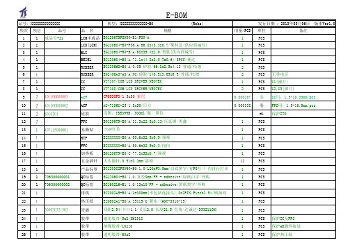
E-BOM
品号:XXXXXXXXXXXXXX
机型:XXXXXXXXXXXXX-B0
(Rohs)
项次 项层
品号
品名
规格
53 2 54 2 55 2 56 2
贴片电阻 贴片电阻 贴片电容 贴片电容
0 Ohm ±5% SMD 1206 Uniohm 470 Ohm ±5% SMD 0603 Uniohm 20PF ±5% 50V SMD 0603 SAMSUNG 100NF ±10% 50V SMD 0603 SAMSUNG
PCS
PCS PCS PCS PCS PCS
PCS PCS
PCS
PCS
PCS
PCS 保护IC及FPC PCS 保护AK脚焊接处 PCS 保护热压纸
品号:XXXXXXXXXXXXXX
项次 项层
品号
27 1 28 1
29 1
30 1
31 1
32 1
33 1
34 1
35 1
36 1
37 1
38 1
39 1
57 2 58 2
钽电容 4.7UF/16V ±10% SMD A型 AVX 贴片三极管 PMBT3906 SMD S0T-23 NXP
59 2 0000
跳点
加锡短接
OUTLINE版本:A版
Pride Mobility 量子 6000Z系列产品说明书

This IPB contains all informationfor the following models:Quantum 6000Z,Quantum 6000ZHD,and Quantum 6400Z.Quantum 6000Z Series®ACN# 088 609 661I llustrated P arts B reakdownUSYour new Pride Illustrated Parts Breakdown (IPB) Manual has been compiled from the latest product information available at the time of publication. Pride Mobility Products reserves the right to make changes and updates to this manual and to the product(s) it represents. Any changes, updates, or improvements to the product(s) may result in slight differences between this manual and the product you purchased.An IPB is an illustrated parts listing of all product components which have maintenance significance. IPB’s utilize “exploded”drawings to detail the individual components for each assembly and an itemized list of reference numbers, part numbers, descriptions, and quantities per assembly. Some parts may be included in an assembly but may not be available for pur-chase separately. Refer to the parts list to locate the part numbers for assemblies and components for ordering what you need.To achieve proper identification and relationship of detail parts and next higher assemblies, parts listings are presented in a convenient alphanumeric reference system. Reference numbers for parent assemblies identify one part number that can be used to order all of the components listed within it. Components of an assembly will have the same alpha character as its parent assembly.For example, the parent assembly part number using reference number of A1 — A4 is the only number you need to place an order for parts with references of A1, A2, A3, and A4. Instead of ordering 4 separate parts, use the parent assembly part number to get the complete assembly.Master assembly part numbers have reference numbers that include several subassemblies. By ordering parts using master assembly part numbers, you can save a lot of time and reduce the chance for error.For example, A1 — G10, a master assembly reference number, includes all components of assemblies A, B, C, D, E, F, and G. Use caution when ordering assemblies. Check to see if a master assembly part number exists for the com-ponents that you need. If an entire master assembly is not needed, then the individual assembly part number (i.e. for reference number G1 — G10) will be sufficient to use for ordering.Asterisks (*) and NOTES are used throughout this service manual to point out important information regarding assembly structure and contents.For example, in some illustrations, only the left OR right side is shown. In other drawings, only the front OR back is depicted. The part numbers for ALL components are listed. An asterisk will also be used to indicate which components are not illustrated. Illustrated items without callouts are shown for assembly purposes.Updates to the contents of this IPB will be made on a regular basis. Providers may retrieve updates immediately upon their release by going to the Pride Service Website. The web address is . We welcome any questions or comments regarding the new Pride IPB Manual that you may have.Please note all pricing included with this manual is subject to change without prior notice from Pride.Thank you for choosing products from Pride Mobility Products.Copyright © 2009Pride Mobility Products® CorporationINFMANU3602/Rev.I/121709Quantum 6000Z SeriesPage 2Rev.I/121709Rev.I/121709Page 3Quantum 6000Z SeriesSECTION I.Center/Side Frame AssemblyVersion 3Red............................................................................................................................................................................6Blue.........................................................................................................................................................................10Silver.......................................................................................................................................................................14Orange....................................................................................................................................................................18Black.......................................................................................................................................................................22Version 2Red..........................................................................................................................................................................26Blue.........................................................................................................................................................................30Silver.......................................................................................................................................................................34Orange....................................................................................................................................................................38Black.. (42)SECTION II.Transit Package (46)SECTION III.Anti-tip AssemblyVersion 3Red..........................................................................................................................................................................48Blue.........................................................................................................................................................................52Silver.......................................................................................................................................................................56Orange....................................................................................................................................................................60Black.......................................................................................................................................................................64Version 2Red..........................................................................................................................................................................68Blue.........................................................................................................................................................................72Silver.......................................................................................................................................................................76Orange....................................................................................................................................................................80Black.. (86)SECTION IV.Suspension AssemblyStandard........................................................................................................................................................................88HD (90)SECTION V.Swing Arm AssemblyRed................................................................................................................................................................................92Blue ...............................................................................................................................................................................96Silver............................................................................................................................................................................100Orange.........................................................................................................................................................................104Black. (108)SECTION VI.Articulating Beam AssemblyRed..............................................................................................................................................................................112Blue .............................................................................................................................................................................116Silver............................................................................................................................................................................120Orange.........................................................................................................................................................................124Black. (128)Page 4Rev.I/121709Quantum 6000Z SeriesSECTION VII.Motor AssemblyHigh Speed Hammer, Standard ..................................................................................................................................132High Speed Hammer, HD............................................................................................................................................134H2................................................................................................................................................................................136H2 Accu-Trac (140)SECTION VIII.Controller Assembly (144)SECTION IX.Utility Tray AssemblyVR2, H2 MotorNon-Power Positioning/Profiled............................................................................................................................146Tilt Thru Joystick/Profiled......................................................................................................................................148Tilt Thru Toggle/Profiled........................................................................................................................................150Future Actuator/Profiled........................................................................................................................................152Q-Logic, H2 MotorNon-Power Positioning .........................................................................................................................................154Quantum Ready....................................................................................................................................................156Tilt Thru Toggle.....................................................................................................................................................158Q-Logic, H2 Accu-Trac MotorQuantum Ready/Tilt Thru Toggle..........................................................................................................................160Q-Logic, High Speed MotorNon-Power Positioning, Standard/HD...................................................................................................................162Quantum Ready, Standard/HD.............................................................................................................................164Tilt Thru Toggle, Standard/HD..............................................................................................................................166NE, High Speed MotorNon-Power Positioning, HD..................................................................................................................................168Tilt Thru Toggle, HD..............................................................................................................................................170NE+, High Speed MotorNon-Power Positioning, HD..................................................................................................................................172Quantum Ready/Tilt Thru Toggle, HD (174)SECTION X.Wiring Loom/Front StabilizerStandard......................................................................................................................................................................176Power Seating. (178)SECTION XI.Footrest AssemblyPlatform.......................................................................................................................................................................180Mounting BracketStandard ...............................................................................................................................................................182Super Low Tilt.......................................................................................................................................................186High Mount............................................................................................................................................................188Super Low/High Mount .. (190)SECTION XII.Shroud AssemblyStandard......................................................................................................................................................................192Super Low...................................................................................................................................................................194Super Low Tilt, TB2/Lift & Tilt......................................................................................................................................196Power Seating. (198)Rev.I/121709Page 5Quantum 6000Z SeriesSECTION XIII.Seat Tower Assembly (200)SECTION XIV.Wheel AssemblyBlack SpokePneumatic.............................................................................................................................................................202Flat-free.................................................................................................................................................................203Silver SpokePneumatic.............................................................................................................................................................204Flat-free.. (205)SECTION XV.Owner’s PackageQuantum 6000Z/Q6000ZHD (206)SECTION XVI.Decal PackageQuantum 6000Z/Q6000ZHD .......................................................................................................................................207Quantum 6400Z.. (208)APPENDIX A.Electrical System DiagramVR2, H2 MotorNon-Power Positioning/Profiled............................................................................................................................209Tilt Thru Joystick/Profiled......................................................................................................................................210Tilt Thru Toggle/Profiled........................................................................................................................................211Future Actuator/Profiled........................................................................................................................................212Q-Logic, H2 MotorNon-Powering Positioning.....................................................................................................................................213Quantum Ready....................................................................................................................................................214Tilt Thru Toggle.....................................................................................................................................................215Q-Logic, H2 Accu-Trac MotorQuantum Ready/Tilt Thru Toggle..........................................................................................................................216Q-Logic, High Speed MotorNon-Power Positioning, Standard/HD...................................................................................................................217Quantum Ready, Standard/HD.............................................................................................................................218Tilt Thru Toggle, Standard/HD..............................................................................................................................219NE, High Speed MotorNon-Power Positioning, HD..................................................................................................................................220Tilt Thru Toggle, HD..............................................................................................................................................221NE+, High Speed MotorNon-Power Positioning, HD..................................................................................................................................222Quantum Ready/Tilt Thru Toggle, HD. (223)Page 6Rev.I/121709Quantum 6000Z SeriesRev.I/121709Page 7Quantum 6000Z SeriesThe parts list is continued on the subsequent pages.Page 8Rev.I/121709Quantum 6000Z SeriesRev.I/121709Page 9Quantum 6000Z SeriesThe parts list is continued from the previous pages.Page 10Rev.I/121709Quantum 6000Z SeriesThe parts list is continued on the subsequent pages.The parts list is continued from the previous pages.The parts list is continued on the subsequent pages.The parts list is continued from the previous pages.The parts list is continued on the subsequent pages.The parts list is continued from the previous pages.The parts list is continued on the subsequent pages.The parts list is continued from the previous pages.Version #2. Applicable to Serial Number J9620607001S10 and subsequent. Retrofits all previous generations.The parts list is continued on the subsequent pages.Version #2. Applicable to Serial Number J9620607001S10 and subsequent. Retrofits all previous generations.The parts list is continued from the previous pages.Version #2. Applicable to Serial Number J9620607001S10 and subsequent. Retrofits all previous generations.The parts list is continued on the subsequent pages.Version #2. Applicable to Serial Number J9620607001S10 and subsequent. Retrofits all previous generations.The parts list is continued from the previous pages.Version #2. Applicable to Serial Number J9620607001S10 and subsequent. Retrofits all previous generations.The parts list is continued on the subsequent pages.Version #2. Applicable to Serial Number J9620607001S10 and subsequent. Retrofits all previous generations.The parts list is continued from the previous pages.Version #2. Applicable to Serial Number J9620607001S10 and subsequent. Retrofits all previous generations.The parts list is continued on the subsequent pages.Version #2. Applicable to Serial Number J9620607001S10 and subsequent. Retrofits all previous generations.The parts list is continued from the previous pages.Version #2. Applicable to Serial Number J9620607001S10 and subsequent. Retrofits all previous generations.The parts list is continued on the subsequent pages.Version #2. Applicable to Serial Number J9620607001S10 and subsequent. Retrofits all previous generations.The parts list is continued from the previous pages.The parts list is continued on the subsequent pages.。
ZLB系列产品说明书
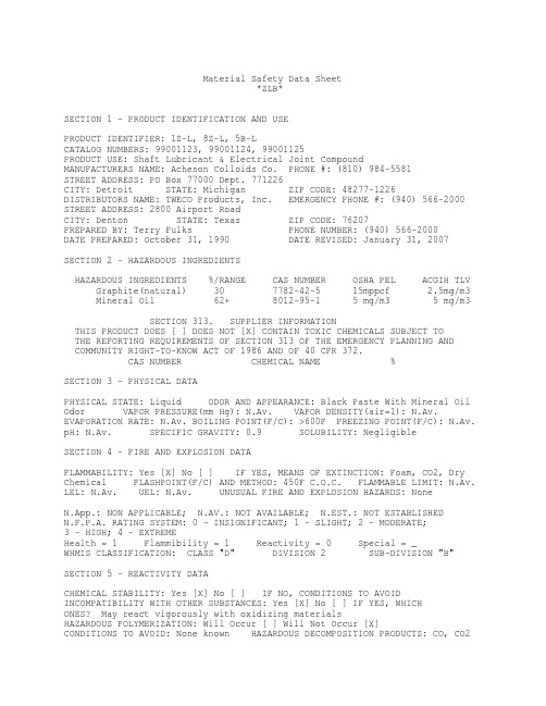
Material Safety Data Sheet*ZLB*SECTION 1 - PRODUCT IDENTIFICATION AND USEPRODUCT IDENTIFIER: 1Z-L, 8Z-L, 5B-LCATALOG NUMBERS: 99001123, 99001124, 99001125PRODUCT USE: Shaft Lubricant & Electrical Joint CompoundMANUFACTURERS NAME: Acheson Colloids Co. PHONE #: (810) 984-5581STREET ADDRESS: PO Box 77000 Dept. 771226CITY: Detroit STATE: Michigan ZIP CODE: 48277-1226DISTRIBUTORS NAME: TWECO Products, Inc. EMERGENCY PHONE #: (940) 566-2000STREET ADDRESS: 2800 Airport RoadCITY: Denton STATE: Texas ZIP CODE: 76207PREPARED BY: Terry Fulks PHONE NUMBER: (940) 566-2000 DATE PREPARED: October 31, 1990 DATE REVISED: January 31, 2007SECTION 2 - HAZARDOUS INGREDIENTSHAZARDOUS INGREDIENTS %/RANGE CAS NUMBER OSHA PEL ACGIH TLVGraphite(natural) 30 7782-42-5 15mppcf 2.5mg/m3 Mineral Oil 62+ 8012-95-1 5 mg/m3 5 mg/m3SECTION 313. SUPPLIER INFORMATIONTHIS PRODUCT DOES [ ] DOES NOT [X] CONTAIN TOXIC CHEMICALS SUBJECT TOTHE REPORTING REQUIREMENTS OF SECTION 313 OF THE EMERGENCY PLANNING ANDCOMMUNITY RIGHT-TO-KNOW ACT OF 1986 AND OF 40 CFR 372.CAS NUMBER CHEMICAL NAME %SECTION 3 - PHYSICAL DATAPHYSICAL STATE: Liquid ODOR AND APPEARANCE: Black Paste With Mineral OilOdor VAPOR PRESSURE(mm Hg): N.Av. VAPOR DENSITY(air=1): N.Av.EVAPORATION RATE: N.Av. BOILING POINT(F/C): >600F FREEZING POINT(F/C): N.Av.pH: N.Av. SPECIFIC GRAVITY: 0.9 SOLUBILITY: NegligibleSECTION 4 - FIRE AND EXPLOSION DATAFLAMMABILITY: Yes [X] No [ ] IF YES, MEANS OF EXTINCTION: Foam, CO2, DryChemical FLASHPOINT(F/C) AND METHOD: 450F C.O.C. FLAMMABLE LIMIT: N.Av.LEL: N.Av. UEL: N.Av. UNUSUAL FIRE AND EXPLOSION HAZARDS: NoneN.App.: NON APPLICABLE; N.AV.: NOT AVAILABLE; N.EST.: NOT ESTABLISHEDN.F.P.A. RATING SYSTEM: 0 - INSIGNIFICANT; 1 - SLIGHT; 2 - MODERATE;3 - HIGH;4 - EXTREMEHealth = 1 Flammibility = 1 Reactivity = 0 Special = _WHMIS CLASSIFICATION: CLASS "D" DIVISION 2 SUB-DIVISION "B"SECTION 5 - REACTIVITY DATACHEMICAL STABILITY: Yes [X] No [ ] IF NO, CONDITIONS TO AVOIDINCOMPATIBILITY WITH OTHER SUBSTANCES: Yes [X] No [ ] IF YES, WHICHONES? May react vigorously with oxidizing materialsHAZARDOUS POLYMERIZATION: Will Occur [ ] Will Not Occur [X]CONDITIONS TO AVOID: None known HAZARDOUS DECOMPOSITION PRODUCTS: CO, CO2ZLB Page 2SECTION 6 - HEALTH HAZARD DATAROUTE OF ENTRY: SKIN CONTACT [ ] SKIN ABSORPTION [X] EYE CONTACT [X]INHALATION [X] INGESTION [ ]EFFECTS OF ACUTE/CHRONIC EXPOSURE TO PRODUCT: Irritation of the eyes,Dermatitis CARCINOGENICITY: No SIGNS AND SYMPTOMS OF EXPOSURE: Irritationof the skin and eyes MEDICAL CONDITIONS GENERALLY AGGRAVATED BY EXPOSURE: Pre-existing skin disorders EMERGENCY AND FIRST AID PROCEDURES: SKIN: Washthoroughly with soap and water EYES: Flush immediately with water for15 minutes, get medical attention. INGESTION: No ill effects expectedINHALATION: No ill effects expectedSECTION 7 - PRECAUTIONS FOR SAFE HANDLING AND USELEAK AND SPILL PROCEDURE: Remove any source of ignition, scoop up as much aspossible, cover remainder with absorbent material & place in non-leakingcontainer for disposal. WASTE DISPOSAL METHOD: Dispose of in accordance withFederal, State & Local regulationsPRECAUTIONS TO BE TAKEN IN HANDLING AND STORING: Store away from sparks, openflames, or excessive heatSECTION 8 - CONTROL MEASURESRESPIRATORY PROTECTION: Not needed for this product. As required for cuttingand welding. GLOVES: Oil resistant RESPIRATOR: not needed EYE: Safetyor chemical goggles FOOTWEAR: N.App. CLOTHING: As required for weldingOTHER: N.Est.VENTILATION: Not normally needed WORK/HYGIENIC PRACTICES: Normal HygieneREFERENCES:"Chemical Guide To OSHA Hazard Communication Standard" First Edition"Handbook Of Toxic And Hazardous Chemicals and Carcinogens" Second Edition "Registry Of Toxic Effects Of Chemical Substances""NIOSH Pocket Guide to CHEMICAL HAZARDS" June 1994THIS DATA IS OFFERED IN GOOD FAITH AS TYPICAL VALUES. THIS IS NEITHER ANEXPRESSED NOR IMPLIED PRODUCT SPECIFICATION. RECOMMENDED HANDLING PROCEDURESAND HYGIENE ARE BELIEVED TO BE ACCURATE, HOWEVER, THESE RECOMMENDATIONS SHOULDBE REVIEWED IN THE SPECIFIC CONTEXT OF INTENDED USE AND DETERMINED APPROPRIATEBY THE USER.。
UHA1R-0060L

UHA1R-0060L一、前言:艾默生Adapt系列1-20K UPS是基于艾默生的全球技术平台,新开发的面向机房环境的升级产品。
此款产品无论从性能、方案能力以及性价比都较以往型号有重大提升,体现了小型UPS的业界最新技术成果以及最新的应用趋势,将作为面向中小机房IT 应用的全新一代产品,满足国内客户对小型UPS的新要求。
二、产品特点:(一)、Adapt系列UPS的产品定位?(1)、适用于服务器机房等区域,保护服务器、网络通信等关键设备;(2)、完全匹配艾默生易睿TM机房整体方案;(3)、黑色机身设计突显了与服务器、机柜和谐搭配;(4)、提供丰富机架选件,方便机架内的配电/监控等功能的一体化实施;(二)、Adapt系列UPS如何确保供电的高可靠?(1)、双变换在线式设计,市电掉电无中断;(2)、支持N+X冗余方式,实现系统可靠性的大幅提升;(3)、DSP全数字控制,输出稳压精度高;(4)、采用最新IGBT器件,实现输入超宽抗电网波动范围;(5)、输入标配防浪涌电路,实现卓越的抗电网浪涌能力;(三)、Adapt系列UPS如何带来绿色环保?(1)、整机效率高达92%以上,节能效益明显;(2)、输入功率因数高达0.99,电能利用率高;(3)、满足欧盟RoHS指令,物料/工艺无有毒物质;(4)、可调速智能风扇,风扇转速自适应调节,有效节能;(5)、提供ECO运行模式,效率高达98%,显著节能;(四)、Adapt系列UPS如何为您省钱?(1)、高达0.9的输出功率因数,带载量提升20-30%,匹配最新服务器的用电特性;(2)、系统效率高,省电、运行成本低;(3)、功率密度高,整机2-3U,占用机架空间小,节省机架数量;(五)、Adapt系列UPS如何方便的维护?(1)、全系列兼容机架/塔式安装方式;(2)、超大尺寸LCD和LED显示,各类运行数据/系统状态/历史情况一目了然;(3)、操作显示面板旋转设计,可随安装方式不同自由调整角度,方便直观;(六)、Adapt系列UPS如何提高方案的可用性?(1)、兼容三单/单单(5/10K),三单/三三(16/20K)多种应用场合;(2)、支持软线并联运行(最大4台,3+1/2+2/4+0可选),且无需并机插框,系统容量随意扩充;(3)、可通过级联电池模块方便地延长后备时间;(七)、Adapt系列UPS如何满足各种监控需求?(1)、提供USB单机监控端口;(2)、提供可采集环境量的SIC网络适配卡,支持服务器自动安全关机功能;(3)、后台软件兼容多种操作系统(Windows/Linux/HP-UX/Sun Solaris/IBM AIX等),兼容艾默生机房监控平台SiteMonitor,支持Web监控;(4)、提供Mib库,方便接入各类NMS网管系统;(八)、Adapt系列UPS如何保护和延长电池组寿命?(1)、超宽输入电压/频率范围,有效减少电池放电几率,延长寿命;(2)、温度补偿功能,减少环境温度对电池寿命的影响;(3)、超强充电能力,有效缩短电池回充时间;(4)、电池组节数设置灵活,便于电池系统的利旧(16/20K) ;(5)、支持共用电池组(16/20K),节省电池投资;三、产品技术参数:(一)、输入参数1、整流器类型:IGBT整流;2、额定电压:220Vac/380Vac 单相三线/三相四线;3、输入电压范围:120Vac~276Vac;4、输入频率范围:45Hz~55Hz;5、输入功率因数:满载≥0.99;单相≥0.95;(二)、电池1、电池类型:铅酸免维护蓄电池;2、充电能力:标机回充至90%,<3h;3、电池模块型号:U16-07C1;4、电池模块规格:435W×640D×85H (机架内高度 2U), 50KG,12V/7.2AH*16;(三)、输出参数:1、额定功率:5KVA/4.5KW;2、额定电压:单相220Vac;3、电压稳定度:3%;4、频率稳定度:0.25%;5、输出电压波形畸变率<2%线性负载;<5%非线性负载;6、负载最大峰值因数3:1(满足IEC62040-3);7、阶跃型负载能力:100%;8、输出方式:端子排;9、过载能力(% 额定负载) : 125%额定电压1min;(四)、系统参数及标准:1、变换类型:双变换在线式;2、能否实现并机:支持最大3+1并机;3、安装方式:机架式/塔式兼容;4、整机效率:高达92%;5、切换时间:0ms;6、噪声<50dB;7、语言:中英文;8、是否有LCD显示:是(标配);9、安规:IEC/EN 62040-1-1;10、电磁兼容:IEC/EN 62040-2;IEC/EN61000-3-11;IEC/EN 61000-3-12;YD/T 1095-2008;11、浪涌保护:IEC/EN 62040-2;12、防护类型:IP20;13、体积:435W×625D×85H (2U,带电池4U);14、重量:17 Kg,不含电池;15、保修:3年;(五)、通信及管理:1、接口类型:USB/智能卡槽(干接点卡/干接点扩展卡/SIC卡/Modbus 卡/RS485卡);2、管理软件:SiteMonitor;(六)、环境参数:1、运行温度:0~40℃;2、相对湿度:5~95%,无凝露;3、最大海拔高度<2000m,超过2000m时参照GB/T 3859.2降额使用;四、适用对象1、服务器;2、存储器;3、网络设备;4、ATM;5、VoIP;6、通讯设备;7、自动化设备;8、精密仪器;9、医疗诊断设备等输入电压精度要求较高的设备。
洛克威爾自動化 PowerFlex 750 系列交流變頻器 技術資料说明书

技術資料PowerFlex 750 系列交流變頻器原始說明主題頁次其他資源2產品概述2認證和規格6設計考量11保險絲及斷路器額定值36電纜考量事項59馬達考量事項61尺寸及重量64變頻器選項1152洛克威爾自動化出版品 750-TD001H-ZC-P - 2013 年 6 月PowerFlex 750 系列交流變頻器其他資源這些文件包含與洛克威爾自動化產品相關的其他資訊。
您可以至以下網址檢視或下載出版品:/literature/。
若要訂購書面的技術文件,請向本地 Allen-Bradley 自動化經銷商或洛克威爾銷售代表洽詢。
產品概述PowerFlex 750 系列是功能強大的交流變頻器系列,不僅易於使用,而且為眾多不同的工業應用系統提供絕佳彈性及效能。
PowerFlex 753 提供的一般用途控制器適用於功率最高達 350HP 及250kW 的應用系統。
PowerFlex 755 提供高達 2000HP 及 1500kW 的最大彈性及效能。
以下是 PowerFlex 750 系列具備的重要功能,善用這些功能所帶來的優勢可大幅提高產能。
•DeviceLogix ™ — 內嵌式控制器技術,支援離散輸出及變頻器控制功能之操作,變頻器更內建離散輸入和變頻器狀態資訊。
•預測診斷系統 — 讓變頻器隨時掌握影響冷卻風扇使用壽命及繼電器輸出的資訊。
此外,亦可編輯變頻器的程式,以監控機器或馬達軸承的運行時間。
•選項卡 — 每個變頻器都具備插槽式架構。
提供兩種產品共通的硬體控制選項,有助您降低庫存及零件的需求。
•安全扭力關斷及安全速度監控 — 可根據您的應用系統需求提供安全層級的選擇。
•通訊 — PowerFlex 755 附帶內建乙太網路連接埠。
可利用通訊模組輕鬆新增乙太網路至 PowerFlex 753。
•I/O — 適用額外類比和離散 I/O 之選項卡。
PowerFlex 753 附帶內建 I/O ,可透過選項卡輕鬆擴充。
HIP4080AIBZ;HIP4080AIPZ;HIP4080AIP;HIP4080AIBZT;HIP4080AIBT;中文规格书,Datasheet资料

Copyright Harris Corporation 1995, Copyright Intersil Americas Inc. 2003, 2004. All Rights Reserved
All other trademarks mentioned are the property of their respective owners.
1 /
CAUTION: These devices are sensitive to electrostatic discharge; follow proper IC Handling Procedures.
1-888-INTERSIL or 321-724-7143 | Intersil (and design) is a registered trademark of Intersil Americas Inc.
CHARGE PUMP
DIS 3
LEVEL SHIFT AND LATCH
TURN-ON DELAY
OUT 5
IN+ 6
+
IN_ 7
-
HDEL 8
LDEL 9
VSS 4
TURN-ON DELAY
AHB 10
X1.HL006A.K11.001-1.厂家使用说明书.SL系列螺杆机组.V100B05

-30℃~85℃,≤85%RH非凝露
开关量输出
19个继电器
单个继电器负载≤400W(电流≈2A);
同一公共端的继电器总负载≤1KW(电流≈5A)
开关量输入
19个无源信号输入
切勿接入电源,外接负载电阻≤2KΩ
模拟量输入
9路温度探头
7路NTC,2路NTC和PT1000兼容
3路标准信号输入
4~20MA、0~5V、0~10V可选
注:自动模式在【制热切换方式】为切换冷媒时才有效。
3.2.2
参数:
【控制温度机组选择】
【控制对象】
【制冷设定温度】
【制热设定温度】
【设定温度补偿系数】
【设定温度最大补偿值】
【起始补偿环温】
1)【控制温度机组选择】参数决定控制温度探头,例如【控制温度机组选择】设为1时表示选择RLAN网络中1号机组的系统温度为控制温度;当所选择的机组的空调侧的无法正常运行或系统探头都有故障时,选择网络中正常机组的系统温度替代。
上电后进入倒计时界面,10S后进入主界面。进入主界面后,按菜单上各个按钮可进入其他界面。如果要设置参数,需要先登录,登录后可以看到相应权限的参数。
在每个界面,都可以按右上角“帮助”键获得对应的提示。
图2.11界面结构图
2.2
开机倒计时完成后进入主界面。主界面有两种情况:
a)只有一个机组时,只有一种主界面。
脉冲式:当开关动作时,如果系统处于停止状态,则启动系统;
如果系统处于启动状态,则停机。
3.1.4
通过联网监控进行开关机动作。
3.1.5
参数:
【来电自启动设置】
禁用:不使用该功能;
来电启动:上电完成后,自动启动机组运行。
Chroma 62000B系列模块化直流电源说明书

Chroma's new 62000B series of Modular DC Power Supplies offer many unique features for Burn-in and plating/electrolysis applications. The features include a N+1 redundancy, high power densities, hot-swappable maintenance, remote ON/OFF and programmable control via the CAN bus.The 62000B family offers 5 types of power module with ranging from 1V to 150V, current from 10A to 90A, and offers two mainframe type of six and three position. The six position mainframe can envelop in up to six power modules paralleled operation for 9KW power output. The 62000B can easily parallel up to fourteen mainframe to 120KW with current sharing and CAN bus control for bulk power applications.The Modular DC Power Supplies of 62000B are very cost effective with high power density and low current ripple. These instruments have be designed for burn-in applications such as the LCD panels, DC-DC converters, power inverters, notebook computers, battery chargers and many other types of electronic devices.Modern power factor correction circuitry is incorporated in 62000B providing an input power factor above 0.98 to meet the IEC requirements. This PFC correction circuity not only reduces the input current draw and to greatly reduce generation of input current harmonics. Optional graphic Soft Panels and CAN bus control allow for control and monitoring of the power system using an easy to use graphical interface.MODULAR DC POWER SUPPL Y MODEL 62000B SERIES1981Equipped with the functionality of N+1 redundancy and hot-swap, the 62000B Series of modular DC power supplies are most applicable for 24 hours non-stop applications such as the SMD plating production lines, as well as product life burn-in test for ITproducts like DC converters, LCD backlight inverters and routers.For continuous operation applications the modular hot-swap design allows engineers to replace the failure unit on-site without shutting down the entire system.M o d u l a r D C P o w e r S u p p l y f o r B u r n -i n & P l a t i n g A p p l i c a t i o n sThe 62000B modular power supplies are capable of providing high power output up to 120KW/2000A with minimal specification degradation via CSU(Control & Supervisor Unit). Each chassis is designed to accommodate a maximum of 9KW and include current sharing capability to ensure system stability. In addition, for convenient control of even large power systems, a CSU is provided to set and display output and protection circuits via a standard CAN bus communication protocol.Available Power Ratings A620007 CSU Key Features:■ Stand-alone controller for paralleled 62000B DC power for bulk power ■ Digital encoder knobs and function keys■ Simultaneous display of output voltage and current ■ Standard Analog programmable interface ■ Standard CAN Bus■ Optional Ethernet interface ■ User define I/O interfaceController Area Network (CAN) is a multicast shared, differential serial bus standard. CAN was specifically designed to be robust inelectromagnetically noisyenvironments and can utilize a differential balanced line like RS-485. Introduced by Bosch in 1986 for in-vehicle networks in cars, it is used in myriad applications including factory automation, building automation, aircraft and aerospace as well as in cars, trucks and buses. CAN bus replaced bulky wiring harnesses with a two-wire differential cable. CAN provides services at layers 1 and 2 of the OSI model and uses a broadcast method for placing frames on the wire. CAN provides low-speed, fault-tolerant transmission of 125 Kbps up to 40 meters, which can function over one wire if a short occurs. Transmission without fault tolerance is provided up to 1 Mbps and 40 meters, and distances up to 1 km are achieved with bit rates of 50 Kbps. Bit rates up to 1 Mbit/s are possible at network lengths below 40m. Decreasing the bit rate allows longer network distances (e.g. 125 kbit/s at 500 m).A620007 Control & Supervisor UnitFRONT PANEL 1. OUTPUT ENABLED LED 2. FAULT INDICATOR 3. OUTPUT VOLTAGE READOUT 4. VOLTAGE TRIMMER (1V-100%)5. OUTPUT CURRENT READOUT 6. CURRENT TRIMMER (1A-100%)7. OUTPUT ENABLE/DISABLE SWITCHREAR PANEL8. CURRENT SHARING CONNECTOR (FOR MAINFRAME)9. REMOTE SENSE CONNECTOR10. I/O CONNECTOR (INCLUDES REMOTE ON/OFF, DC OK, AUX POWER)11. CAN DIP ADDRESS SWITCH12. CAN BUS COMMUNICATIONS PORT (OPTIONAL)13. OUTPUT TERMINALS 14. AC INPUT TERMINAL BLOCKModel 62000B SeriesFRONT PANEL 1. OVP INDICATOR 2. VOLTAGE READOUT 3. OTP INDICATOR 4. AC-FAULT INDICATOR 5. CURRENT READOUT 6. MODULE ERROR INDICATOR 7. CV MODE INDICATOR 8. CC MODE INDICATOR9. ON/OFF ENABLE/DISABLE 10. V-SET BUTTON 11. I-SET BUTTON 12. OVP-SET BUTTON 13. I-MAX LIMITED SETTING 14. ROTARY15. AC ON/OFF SWITCH25SOFTPANELREAR PANEL 16. AC INPUT 17. ETHERNET 18. CAN ADDRESS SET 19. DIP SWITCHING FOR SYSTEM SETTING 20. I/O CONTROLINTERFACE INPUT 21. I/O CONTROL INTERFACE OUTPUT 22. TERMINAL-RESISTANCE(CAN)23. CAN BUS to PC 24. CAN BUS to MAINFRAME 25. EXT-V&I SENSE INPUT 26. APG CONTROLMain Operation Menu Program Sequence Function Basic Control Function for 30 ChannelsM o d e l 62000B S e r i e sType A - Control with CSU : User can control via APG, CAN Bus/ Ethernet, and front panel manual control for paralleled operation.Type B - Control without CSU : User can only control via CAN Bus for paralleled operation.Note: The SoftPanel can control four mainframes for paralleled operation.Type C - Control without CSU or PC : User can only control via remote on/off signal for paralleled operation.Note 1 : User can NOT adjust the output voltage when parallel the output.Note 2 : The output voltage will fixed in factory default voltage.Note 3 : If need to adjust the output voltage, please adjust when stand alone. Note 4 : Time delay from output enable until output stable: 10s max.CAN BusCAN BusCAN Bus〕Note*1 : For 50% step load variation with remote sense at maximum output voltageNote*2 : based on rise time of 100msNote*3 : Time for the output voltage to recover within 1% of its rated for a load changed of 25%Note*4 : Six Position Mainframe through CANORDERING INFORMATION62000B-3-1 : Three Position 62000B Mainframe62000B-6-1 : Six Position 62000B Mainframe62015B-15-90 : DC Power Supply Module, 15V/90A/1350W 62015B-30-50 : DC Power Supply Module, 30V/50A/1500W 62015B-60-25 : DC Power Supply Module, 60V/25A/1500W 62015B-80-18 : DC Power Supply Module, 80V/18A/1440W 62015B-150-10 : DC Power Supply Module, 150V/10A/1500W A620007 : Control & Supervisor UnitA620008 : CAN Bus Interface for mainframeA620010 : Rack Mounting Kit for mainframeA620011 : Ethernet Interface for CSUA620012 : AD-Link PCI 7841 CAN Bus CardA620013 : 19" Rack (23U) for 62000B SeriesA620014 : 19" Rack (41U) for 62000B SeriesA620016 : Rack Mounting Kit for CSUA620017 : Softpanel for 62000B SeriesA620018 : NI USB-8473 high-speed USB to CAN interfaceA620019 : USB Interface Control Box for mainframe & CSUA620020 : GPIB Interface Control Box for mainframe & CSU*A620021 : APG Interface Control Box for mainframe*A620022 : RS-485 Interface Control Box mainframe & CSU*Call for availability62000B-E-200908-PDFWorldwide Distribution and Service NetworkDistributed by:JAPANCHROMA JAPAN CORP. NARA Building 11F 2-2-8 Shinyokohama, Kouhokuku, Yokohama-shi, Kanagawa, 222-0033 JapanTel: +81-45-470-2285 Fax: +81-45-470-2287 http://www.chroma.co.jp U.S.A.CHROMA SYSTEMS SOLUTIONS, INC. 25612 Commercentre Drive, Lake Forest, CA 92630-8830 Tel: +1-949-600-6400 Fax: +1-949-600-6401Toll Free: +1-866-600-6050 E-mail:*******************Developed and Manufactured by : CHROMA ATE INC.致茂電子股份有限公司HEADQUARTERS No. 66, Hwa-Ya 1st Rd.,Hwa-Ya Technology Park, Kuei-Shan Hsiang,33383 Taoyuan County, Taiwan Tel: +886-3-327-9999 Fax: +886-3-327-8898 EUROPECHROMA ATE EUROPE B.V.Morsestraat 32, 6716 AH Ede,The NetherlandsTel: +31-318-648282Fax: +31-318-648288E-mail:****************** CHINACHROMA ELECTRONICS(SHENZHEN) CO., LTD.8F, No.4, Nanyou Tian AnIndustrial Estate, Shenzhen,China PC: 518052Tel: +86-755-2664-4598Fax: +86-755-2641-9620。
HIP4081AIBZ中文资料

Thermal Information
Thermal Resistance (Typical, Note 1) θJA (°C/W) SOIC Package . . . . . . . . . . . . . . . . . . . . . . . . . . . . . 85 DIP Package . . . . . . . . . . . . . . . . . . . . . . . . . . . . . . 75 Storage Temperature Range . . . . . . . . . . . . . . . . . . . -65°C to 150°C Operating Max. Junction Temperature . . . . . . . . . . . . . . . . . . 125°C Lead Temperature (Soldering 10s)). . . . . . . . . . . . . . . . . . . . . 300°C (For SOIC - Lead Tips Only
AHB 10 HIGH VOLTAGE BUS ≤ 80VDC
UNDERVOLTAGE
CHARGE PUMP
LEVEL SHIFT AND LATCH
DRIVER 11
AHO CBS AHS 12
VDD 16 AHI 7 TURN-ON DELAY
DBS DIS 3 15 VCC
TO VDD (PIN 16)
NOTE: Intersil Pb-free products employ special Pb-free material sets; molding compounds/die attach materials and 100% matte tin plate termination finish, which is compatible with both SnPb and Pb-free soldering operations. Intersil Pb-free products are MSL classified at Pb-free peak reflow temperatures that meet or exceed the Pb-free requirements of IPC/JEDEC J Std-020B.
APEX Home Gym AX-2109.1 Owner's Manual

NOTE:Please read all instructions carefully before using thisproductTable of ContentsSafety Notice Hardware Identifier Assembly InstructionParts List Resistance ChartWarrantyOrdering PartsModel AX-2109.1Retain This Manual for Reference100506OWNER'S MANUALAPEX Home GymAX-2109.1IMPEX® INC.14777 DON JULIAN RD., CITY OF INDUSTRY, CA 91746 Tel: (800) 999-8899 Fax: (626) 961-9966**********************TABLE OF CONTENTSBEFORE YOU BEGIN (1)IMPORTANT SAFETY NOTICE (2)HARDWARE PACK (4)ASSEMBLY INSTRUCTIONS (7)EXPLODED DIAGRAM (19)PARTS LIST (20)RESISTANCE CHART (21)WARRANTY (22)ORDERING PARTS (22)BEFORE YOU BEGINThank you for selecting the APEX AX-2109.1 HOME GYM by IMPEX®FITNESS PRODUCTS. For your safety and benefit, read this manual carefully before using the machine. As a manufacturer, we are committed to provide you complete customer satisfaction. If you have any questions, or find there are missing or damaged parts, we guarantee you complete satisfaction through direct assistance from our factory. To avoid unnecessary delays, please call our TOLL-FREE customer service number. Our Customer Service Agents will provide immediate assistance to you.Toll-Free Customer Service Number1-800-999-8899Mon. – Fri. 9 a.m. – 5 p.m. PST**********************IMPORTANT SAFETY NOTICEPRECAUTIONSThis exercise machine is built for optimum safety. However, certain precautions apply whenever you operate a piece of exercise equipment. Be sure to read the entire manual before you assemble or operate your machine. In particular, note the following safety precautions:1. Keep children and pets away from the machine at all times. DO NOTleave children unattended in the same room with the machine.2. Only one person at a time should use the machine.3. If the user experiences dizziness, nausea, chest pain, or any other abnormalsymptoms, STOP the workout at once. CONSULT A PHYSICIAN IMMEDIATELY.4. Position the machine on a clear, leveled surface. DO NOT use the machinenear water or outdoors.5. Keep hands and feet away from all moving parts.6. Always wear appropriate workout clothing when exercising. DO NOT wearrobes or other clothing that could become caught in the machine. Runningor aerobic shoes are also required when using the machine.7. Use the machine only for its intended use as described in this manual. DONOT use attachments not recommended by the manufacturer.8. Do not place any sharp object around the machine.9. Disabled person should not use the machine without a qualified person orphysician in attendance.10. Before using the machine to exercise, always do stretching exercises toproperly warm up.11. Never operate the machine if the machine is not functioning properly.12. A spotter is recommended during exercise.13. Do not intend to insert weight selector pin while the weight stack or top plateis in elevated position.14. Be certain the weight Selector Pin is completely inserted.15. Never use dumbbells or other means to increase the weight resistance. Use only weight plates provided by manufacturer.16. This machine is designed and intended for home and consumer use only, not forcommercial use.CARE AND MAINTENANCE1. Lubricate moving parts with WD-40 or light oil periodically.2. Inspect and tighten all parts before using the machine.3. Immediately replace worn or damaged parts obtained from the manufacturer.4. The machine can be cleaned using a damp cloth and mild non-abrasive detergent.DO NOT use solvents.5. Maximum user’s weight: 300 lbs. (135 kg.)6. Assembled Dimensions: 62” x 41” x 81” (157.5x104x205.75 cm)WARNING: BEFORE BEGINNING ANY EXERCISE PROGRAM, CONSULT YOUR PHYSICIAN. THIS IS ESPECIALLY IMPORTANT FOR INDIVIDUALS OVER THE AGE OF 35 OR PERSONS WITH PRE-EXISTING HEALTH PROBLEMS. READALL INSTRUCTIONS BEFORE USING ANY FITNESS EQUIPMENT. IMPEX INC. ASSUMES NO RESPONSIBILITY FOR PERSONAL INJURY OR PROPERTY DAMAGE SUSTAINED BY OR THROUGH THE USE OF THIS PRODUCT.WARNING LABEL PLACEMENTThe warning labels shown here have been placed on the Rear Base and Upper Frame. If the labels are missing or illegible, please call customer service at 1-800-888-8899 for replacements. Apply the labels in the location shown.HARDWARE PACKNOTE: The following parts are not drawn to scale. Please use your own ruler to measure the size.NOTE: The following parts are not drawn to scale. Please use your own ruler to measure the size.ASSEMBLY INSTRUCTIONTools Required for Assembling the Machine: Two Adjustable Wrenches, two Allen Wrenches, and one Philips Screwdriver. NOTE: It is strongly recommended this machine to be assembled by two or more people to avoid possible injury.STEP 1 (See Diagram 1)A.) NOTE: Do not tighten all the Nuts and Bolts until instructed to do so.B.) Connect two Lower Guide Rods (#23) and two Upper Guide Rods (#24) with two M10Stud Bolts (#80). Firmly thread the Rods together.C.) Insert the Lower Guide Rods (#23) into the holes on the Rear Base Frame (#2). Secureit with two M10 x 1” Allen Bolts (#73) and Ø ¾” Washers (#83) from the bottom.D.) Attach the Main Base Frame (#8) to the Rear Base Frame (#2). Secure it with two M10x 2 ½” Carriage Bolts (#79), one 4” Bracket (#30), two Ø ¾” Washers (#83), and two M10 Aircraft Nuts (#85).E.) Attach the Lower Vertical Frame (#3) onto the Main Base Frame (#8). Secure it withtwo M10 x 2 ½” Carriage Bolts (#79), one 4 ¾” Bracket (#29), two Ø ¾” Washers (#83), and two M10 Aircraft Nuts (#85).F.) Attach the Leg Developer Holder (#1) to the Main Base Frame (#8) and Front BasePlate (#15). Secure them together with two M10 x 2 ½” Carriage Bolts (#79), one 4 ¾”Bracket (#29), two Ø ¾” Washers (#83), and two M10 Aircraft Nuts (#85).G.) Attach the Seat Support (#16) to the Leg Developer Holder (#1). Secure it with oneM10 x 2 3/8” Allen Bolt (#71), two Ø ¾” Washers (#83), and one M10 Aircraft Nut(#85).H.) Attach the Seat Support (#16) to the Lower Vertical Frame (#3). Secure it with two M10x 2 ½” Carriage Bolts (#79), one 4 ¾” Bracket (#29), two Ø ¾” Washers (#83), and two M10 Aircraft Nuts (#85).I.) Attach the Upper Vertical Frame (#14) to the Lower Vertical Frame (#3). Secure themwith four M10 x 2 ½” Carriage Bolts (#79), two V-shaped Brackets (#27), four Ø ¾”Washers (#83), and four M10 Aircraft Nuts (#85).J.) Attach the Stopper Frame (#25) to the Upper Vertical Frame (#14). Secure it with one M10 x 2 3/8” Allen Bolt (#71) and Ø ¾” Washer (#83).DIAGRAM 1STEP 2 (See Diagram 2)A.) Slide two Ø2 ½” x 1” Rubber Bumpers (#65) onto the Guide Rods.B.) Slide 11 Weight Plates (#33) onto the Guide Rods. Make sure the deep grooveson the Weight Plates are all facing the back of the machine and downward.Insert the Selector Rod (#17) through the center hole on the Weight Plates.C.) Slide the Selector Stem (#32) onto the Guide Rods.D.) Slide the Ring on the String onto the Selector Rod (#17).E.) Attach the Upper Frame (#4) onto the two Guide Rods. Secure it with two M10 x1” Allen Bolts (#73) and Ø ¾” Washers (#83).F.) Place the Upper Frame (#4) onto the Upper Vertical Frame (#14). Secure themwith two M10 x 2 ½” Carriage Bolts (#79), one 4 ¾” Bracket (#29), two Ø ¾”Washers (#83), and two M10 Aircraft Nuts (#85).G.) Securely tighten all Nuts and Bolts previously installed.H.) Use the Weight Selector Pin (#34) to select number of weight plates to exercise.Each weight plate weights approximately 10 lbs. Please refer to the WeightResistance Chart in page 21.DIAGRAM 210A.) Attach the Front Press Base (#11) to the Upper Frame (#4). Secure it with one Long Axle(#46), two Ø ¾” Washers (#83), and two M10 Aircraft Nuts (#85).B.) Attach the Right Butterfly (#6) to the Front Press Base (#11). Secure it with one Ø 1 ½”Washer (#82), one M6 x 1 ¼” Allen Bolt (#78), Lock Ring (#41), and M6 Aircraft Nut (#86).C.) Slide a Butterfly Foam Roll (#62) onto the Right Butterfly arm. Attach the Right Front PressHandle (#13) to the Right Butterfly. Secure it with a M10 x 1” Allen Bolt (#73) and Ø ¾”Washer (#83).D.) Repeat the Steps B&C above to install the Left Butterfly (#5).E.) Attach a Butterfly Pulley Bracket (#9) to the Upper Vertical Frame (#14). Secure it with oneM10 x 2 3/8” Allen Bolt (#71), two Ø ¾” Washers (#83), and one M10 Aircraft Nut (#85). F.) Attach Swivel Pulley Brackets (#21) to each end of the Butterfly Pulley Bracket. Secure eachBracket with one M10 x 2 ½” Allen Bolt (#70), two Ø ¾” Washers (#83), and one M10 Aircraft Nut (#85). Do Not over tighten! Make sure the Brackets are able to swivel freely.G.) Attach the Backrest Board (#39) to the Vertical Frame. Secure it with two M8 x 3” Allen Bolts(#75) and Ø 5/8” Washers (#84).11A.) Attach the Leg Developer (#7) to the bracket on the Leg Developer Holder (#1). Secure itwith a Leg Developer Axle (#47), two M10 x 5/8” Allen Bolts (#74), and two Ø ¾” Washers (#83).B.) Insert two Foam Roll Tubes (#28) halfway through the holes on the Leg Developer and LegDeveloper Holder. Push four Foam Rolls (#61) onto the Tubes from both ends. Plug four Foam Roll End Caps (#60) into the ends.C.) Place the Seat (#38) onto the Seat Support (#16). Secure it with two M8 x 2 1/8” Allen Bolts(#76) and Ø 5/8” Washers (#84).DIAGRAM 412CABLE LOOP DIAGRAM13STEP 5 (See Diagram 5 & Cable Loop Diagram)A.) Attach the 138” Upper Cable (#35) to the opening at the front of the Upper Frame(#4). Note: The Ball Stopper on the cable should be underneath the Frame. B.) Attach a Pulley (#63) to the opening. Secure it with one M10 x 2 3/8” Allen Bolt(#71), two Pulley Bushings (#50), and one M10 Aircraft Nut (#85).C.) Draw the Cable towards the back of the machine to the second opening on theUpper Frame. Repeat Procedure B above to install a second Pulley with twoPulley Covers (#91).D.) Draw the Cable around the Pulley then pull back towards the opening on theFront Press Base (#11).E.) Attach a Pulley to the opening on the Front Press Base (#11). Secure the Pulleywith one M10 x 5 1/8” Allen Bolt (#68), two Pulley Covers (#91), and M10 Aircraft Nut (#85).F.) Draw the Cable around the Pulley then to the opening on the Upper VerticalFrame (#14). Repeat Procedure B above to install another Pulley with two Pulley Covers (#91).G.) Draw the Cable around the Pulley then downward. Attach the Cable to the upperholes on the two Double Floating Pulley Brackets (#31).H.) Attach a Pulley to the Brackets. Secure it with one M10 x 2” Allen Bolt (#87), twoØ ¾” Washers (#83), two Cable Retainers (#89), and one M10 Aircraft Nut (#85).I.) Leave the bracket hanging for now.J.) Pull the Cable upward to the open bracket underneath the Upper Frame (#4).Repeat H to install a Pulley.K.) Pull the Cable downward between the two Guide Rods to the Selector Rod (#17).Fully thread the bolt at the end of the Cable into the top opening on the Selector Rod.L.) Connect the Lat Bar (#18) to a Short Chain (#49) with a C-clip (#53). Then connect the Short Chain to the Upper Cable with another C-clip.14DIAGRAM 515A.) Attach one end of the 119” Butterfly Cable (#37) to the hook on the Right Butterfly (#6).B.) Draw the Cable to the right Swivel Pulley Bracket (#21).C.) Attach a Pulley to the bracket. Secure it with one M10 x 2” Allen Bolt (#87), two CableRetainers (#89), two Ø ¾” Washers (#83), and one M10 Aircraft Nut (#85).D.) Draw the Cable around the Pulley then downward. Attach the Cable to a Crossed DoubleFloating Pulley Bracket (#20). Attach a Pulley to the bracket. Secure it with one M10 x 2” Allen Bolt (#87), two Cable Retainers (#89), two Ø ¾” Washers (#83), and one M10 Aircraft Nut (#85). Leave the Bracket hanging for now.E.) Pull the Cable around the Pulley then upward to the left Swivel Pulley Bracket. RepeatProcedure C above to install a Pulley.F.) Draw the Cable to the left Butterfly. Attach the end to the hook on the Left Butterfly.16A.) Attach the 128” Lower Cable (#36) to the open bracket on the bottom of the LegDeveloper (#7). Note: The Ball Stopper on the cable should be in front of the pulley not on top.B.) Attach a Pulley to the bracket. Secure it with one M10 x 1 ¾” Allen Bolt (#72), two ؾ” Washers (#83), and one M10 Aircraft Nut (#85).C.) Draw the Cable underneath the Pulley to the opening on the Leg Developer Holder(#1). Attach a Pulley to the opening. Secure it with one M10 x 2 3/8” Allen Bolt (#71), two Pulley Bushings (#50), two Pulley Covers (#91), and one M10 Aircraft Nut (#85).D.) Draw the Cable underneath the Pulley along the Main Base Frame to the opening onthe bottom of the Lower Vertical Frame (#3). Repeat Procedure C above to install another Pulley.E.) Pull the Cable upward to the Crossed Double Floating Pulley Bracket (#20)previously installed in Step-6.F.) Attach a Pulley to the Bracket. Secure it with one M10 x 2” Allen Bolt (#87), two Ø ¾”Washers (#83), two Cable Retainers (#89), and one M10 Aircraft Nut (#85).G.) Draw the Cable around the Pulley then downward to the open bracket on the MainBase Frame. Repeat F to install another Pulley.H.) Pull the Cable around the Pulley then upward to the Double Floating Pulley Bracket(#31) previously installed in Step-5. Repeat F to install another Pulley.I.) Draw the Cable around the Pulley then pull downward to the bracket on the back ofthe Upper Vertical Frame (#14). Secure the Cable to the bracket with one M10 x 1”Allen Bolt (#73), two Ø ¾” Washers (#83), and one M10 Aircraft Nut (#85).J.) Adjust the tension of the Cable by adjusting the Pulley position on the Double Floating Pulley Bracket (#31). If the cables are too loose, move up the Pulley. If the cables are too tight, move down the Pulley.K.) For best performance of the machine, adjust the Cables so the Selector Stem (Top Plate) on the weight stack is ¼” above the first plate. While pinning the weight stack, push down on the Selector Stem to close up the gap then pin the plates. This will remove the slack in the cable system so the range of motion is smooth and tight.L.) Connect the Shiver Bar (#19) to a Long Chain (#48) with a C-clip (#53). Connect the Long Chain to the Lower Cable with another C-clip.17DIAGRAM 718EXPLODED DIAGRAM19PARTS LISTKEY NO. DESCRIPTIONQ’ty1 Leg Developer Holder 12 Rear Base Frame 13 Lower Vertical Frame 14 Upper Frame 15 Left Butterfly 16 Right Butterfly 17 Leg Developer 18 Main Base Frame 19 Butterfly Pulley Bracket 1 10 Lat Bar Warning Label 1 11 Front Press Base 1 12 Left Front Press Handle 1 13 Right Front Press Handle 1 14 Upper Vertical Frame 1 15 Front Base Plate 1 16 Seat Support 1 17 Selector Rod 1 18 Lat Bar 1 19 Shiver Bar 1 20 Crossed Double Floating Pulley Bracket 1 70 M10 x 2 ½” Allen Bolt2 21 Swivel Pulley Bracket 2 22 Shiver Bar Handle 1 23 Lower Guide Rod 2 24 Upper Guide Rod 2 25 Stopper Frame 1 26 Warning Label 1 27 V-shaped Bracket 2 28 Foam Roll Tube 2 29 4 ¾” Bracket 4 30 4” Bracket 1 31 Double Floating Pulley Bracket 2 32 Selector Stem 1 33 Weight Plate 11 34 Weight Selector Pin 1 35 138” Upper Cable 1 36 128” Lower Cable 1 37 119” Butterfly Cable 1 87M10 x 2” Allen Bolt 8 38 Seat 1 39 Backrest Board 1 40 Customer Service Label 1 41 Lock Ring 2 91 PulleyCover 10 42 Ankle Strap 1 43 Top Label 1 44 Butterfly Bushing 2 45 Ø 1 ½” x 1” Bushing 2 46 Long Axle 1 47 Leg Developer Axle 148 15-Link Chain 1 49 6-Link Chain 150 Pulley Bushing 102051 Bottom Label 152 Handle Grip 853 C-clip 454 Manual 155 Rear Base Frame End Cap256 1 5/8” x ¾” End Cap 257 1 ¾” Square End Cap 7 58 1 ½” Square End Cap 2 59 Ø 1” End Cap 1 60 Foam Roll End Cap 461 Foam Roll 4 62 Butterfly Foam Roll 263 Pulley 15 64 Ø 1 ½” x 5/8” Rubber Bumper 1 65 Ø 2 ½” x 1” Rubber Bumper 2 66 Ø 1 ¾” x 1 5/8” Rubber Bumper 1 67 Ø 1’ Bushing 8 68 M10 x 5 1/8” Allen Bolt 1 69 1 ¾” x ¼” Spacer3 71 M10 x 2 3/8” Allen Bolt 8 72 M10 x 1 ¾” Allen Bolt 1 73 M10 x 1” Allen Bolt 7 74 M10 x 5/8” Allen Bolt 2 75 M8 x 2 ¾” Allen Bolt 2 76 M8 x 2 1/8” Allen Bolt 2 77 Guide Rod Label 4 78 M6 x 1 ¼” Allen Bolt 2 79 M10 x 2 ½” Carriage Bolt 14 80 M10 Stud Bolt 2 81 M6 x 5/8” Philips Screw 2 82 Ø 1 ½” Washer 2 83 Ø ¾” Washer 53 84 Ø 5/8” Washer 4 85 M10 Aircraft Nut 36 86 M6 Aircraft Nut2 88 Ø ¾” x 1” Pulley Bushing 289 Cable Retainer 16 90 Cable Retainer Bushing16#6 Allen Wrench (Tool) 2 #5 Allen Wrench (Tool)1AX-2109.1 WEIGHT RESISTANCE CHART Weight Plate Front Press Butterfly Lat Pull Low Pulley1 30 15 30 3040402 422050503 54256060304 667070355 788080406 909090457 102100100508 114110110559 12612012010 138 6013013011 150 65Note: Each plate weights 10 lbs.Numbers are approximate. Actual weights may vary.Values for Butterfly are for each arm.21IMPEX® INC.LIMITED WARRANTYIMPEX Inc. ("IMPEX®") warrants this product to be free from defects in workmanship and material, under normal use and service conditions, for a period of two years on the Frame from the date of purchase. This warranty extends only to the original purchaser. IMPEX's obligation under this Warranty is limited to replacing or repairing, at IMPEX's option.All returns must be pre-authorized by IMPEX. Pre-authorization may be obtained by calling IMPEX Customer Service Department at 1-800-999-8899. All freights on products returned to IMPEX must be prepaid by the customer. This warranty does not extend to any product or damage to a product caused by or attributable to freight damage, abuse, misuse, improper or abnormal usage or repairs not provided by an IMPEX authorized service center or for products used for commercial or rental purposes. No other warranty beyond that specifically set forth above is authorized by IMPEX.IMPEX is not responsible or liable for indirect, special or consequential damages arising out of or in connection with the use or performance of the product or other damages with respect to any economic loss, loss of property, loss of revenues or profits, loss of enjoyments or use, costs of removal, installation or other consequential damages or whatsoever natures. Some states do not allow the exclusion or limitation of incidental or consequential damages. Accordingly, the above limitation may not apply to you.The warranty extended hereunder is in lieu of any and all other warranties and any implied warranties of merchantability or fitness for a particular purpose is limited in its scope and duration to the terms set forth herein. Some states do not allow limitations on how long an implied warranty lasts. Accordingly, the above limitation may not apply to you.This warranty gives you specific legal right. You may also have other rights which vary from state to state. Register on-line at IMPEX® INC.14777 Don JulianCity of Industry, CA 91746ORDERING REPLACEMENT PARTSReplacement parts can be ordered by calling our Customer Service Department toll-free at 1-800-999-8899 during our regular business hours: Monday through Friday, 9 am until 5 pm Pacific standard time.**********************When ordering replacement parts, always give the following information.1. Model2. Description of PartsNumber3. Part4. Date of Purchase22。
EXBVxxxx中文资料

5.08+0.20 –0.10
2.20 +0.20 –0.10
0.70 ±0.20
0.80 ±0.15
0.80 ±0.15
0.50 ±0.15
0.55 ±0.15
(3) Flat Terminal type
A1 A2 EXB18V G T G W P L B B
Type (inches) EXB18V (0201 4)
±0.10
B
W 0.60 ±0.10 1.00 ±0.10 1.00
±0.10
T 0.35 ±0.10 0.35 ±0.10 0.35
±0.10
A1 0.35 ±0.10 0.40 ±0.10 0.45
±0.10
A2 — — 0.35
±0.10
B 0.15 ±0.10 0.18 ±0.10 0.20
May. 2005
元器件交易网
Chip Resistor Array
■
Item Resistance Range Resistance Tolerance 14V,24V,V4V,34V Specifications 10 to 1 M :E24 series J: ±5 % 4 terminal Item 14V,18V (1) Limiting Element Voltage 2HV Max. Rated Continuous 24V,28V,N8V,38V,34V,V4V,V8V Working Voltage S8V Specifications 12.5 V 25 V 50 V 100 V 25 V 50 V 200 V ±200 10 -6/°C(ppm/°C)
Dimensions (mm) L 1.40 ±0.10 W 0.60 ±0.10 T 0.35 ±0.10 A1 0.20 ±0.10 A2 0.20 ±0.10 B 0.10 ±0.10 P (0.40) G 0.20 ±0.10
爱森摩尔Z5型号超压保护器说明说明书

Eaton 210075Eaton Moeller® series Z5 Overload relay, Ir= 200 - 250 A, 1 N/O, 1 N/C, For use with: DILM250, DILM300AGeneral specificationsEaton Moeller® series Z5 Thermal overload relay2100754015082100759Z5-250/FF250146 mm 167 mm 128 mm 1.727 kgIEC/EN 60947UL Category Control No.: NKCR VDE 0660 CECSA Class No.: 3211-03 ULCSA-C22.2 No. 60947-4-1-14 CSA File No.: 012528 UL 60947-4-1 UL File No.: E29184 IEC/EN 60947-4-1 CSAProduct NameCatalog Number EANModel Code Product Length/Depth Product Height Product Width Product Weight CertificationsReset pushbutton manual/autoTrip-free releaseTest/off buttonPhase-failure sensitivity (according to IEC/EN 60947, VDE 0660 Part 102)-25 °C60 °C25 °C40 °CCLASS 10 ADamp heat, constant, to IEC 60068-2-78Damp heat, cyclic, to IEC 60068-2-30IP00Separate mountingDirect mountingDirect attachment/single positioning200 A250 AIII3Overload relay Z5With terminal cover, Protection against direct contact when actuated from front (EN 50274)4000 V (auxiliary and control circuits)8000 V ACFeatures Ambient operating temperature - minAmbient operating temperature - maxAmbient operating temperature (enclosed) - minAmbient operating temperature (enclosed) - maxClassClimatic proofingDegree of protectionMounting methodOverload release current setting - minOverload release current setting - maxOvervoltage categoryPollution degreeProduct categoryProtectionRated impulse withstand voltage (Uimp)Shock resistance10 g, Mechanical, Sinusoidal, Shock duration 10 ms Branch circuits, (UL/CSA)≤ 0.25 %/K, residual error for T > 40° Continuous 25 mm width, Main connection185 mm²2 x (0.75 - 2.5) mm², Control circuit cables1 x (0.75 - 2.5) mm², Control circuit cables1 x (0.75 - 4) mm², Control circuit cables2 x (0.75 - 4) mm², Control circuit cables2/0 - 500 MCM, Main cables2 x (18 - 14), Control circuit cables185 mm²16 mm (Hexagon head spanner SW)8 mmM10 x 35, Terminal screw, Main connectionsM3.5, Terminal screw, Control circuit cables1 x 6 mm, Terminal screw, Control circuit cables, Standard screwdriver2, Terminal screw, Control circuit cables, Pozidriv screwdriver18 Nm, Main cable connection screw/bolt1.2 Nm, Screw terminals, Control circuit cables6 A 1.5 A 1200 A Class L, max. Fuse, SCCR (UL/CSA) 18 kA, SCCR (UL/CSA)1200 A, max. CB, SCCR (UL/CSA)500 A gG/gL, Fuse, Type “1” coordinationSuitable forTemperature compensationTerminal capacity (busbar)Terminal capacity (flexible with cable lug)Terminal capacity (flexible with ferrule)Terminal capacity (solid)Terminal capacity (solid/stranded AWG)Terminal capacity (stranded with cable lug)Width across flatsStripping length (control circuit cable)Screw sizeScrewdriver sizeTightening torqueConventional thermal current ith of auxiliary contacts (1-pole,open)Rated operational current (Ie) at AC-15, 120 VShort-circuit current rating (basic rating)Short-circuit protection rating1.5 A0.9 A0.4 A0.2 A0.9 A0.75 A1000 V440 V, Between auxiliary contacts and main contacts, According to EN 61140240 V AC, Between auxiliary contacts, According to EN 61140 500 V AC, Between main circuits, According to EN 61140R300, DC operated (UL/CSA)B300 at opposite polarity, AC operated (UL/CSA)B600 at opposite polarity, AC operated (UL/CSA)600 VAC600 VAC 500 A gG/gL, Fuse, Type “2” coordinationMax. 6 A gG/gL, fuse, Without welding, Auxiliary and control circuits111143.5 W0 W14.5 W250 A0 WMeets the product standard's requirements.Meets the product standard's requirements.Meets the product standard's requirements.Meets the product standard's requirements.Rated operational current (Ie) at AC-15, 220 V, 230 V, 240 V Rated operational current (Ie) at AC-15, 380 V, 400 V, 415 V Rated operational current (Ie) at DC-13, 110 VRated operational current (Ie) at DC-13, 220 V, 230 V Rated operational current (Ie) at DC-13, 24 VRated operational current (Ie) at DC-13, 60 VRated operational voltage (Ue) - maxSafe isolationSwitching capacity (auxiliary contacts, pilot duty) Voltage rating - maxVoltage rating - max Number of auxiliary contacts (change-over contacts)Number of auxiliary contacts (normally closed contacts) Number of auxiliary contacts (normally open contacts) Number of contacts (normally closed contacts)Number of contacts (normally open contacts)Equipment heat dissipation, current-dependent PvidHeat dissipation capacity PdissHeat dissipation per pole, current-dependent PvidRated operational current for specified heat dissipation (In) Static heat dissipation, non-current-dependent Pvs10.2.2 Corrosion resistance10.2.3.1 Verification of thermal stability of enclosures10.2.3.2 Verification of resistance of insulating materials to normal heat10.2.3.3 Resist. of insul. mat. to abnormal heat/fire by internal elect. effectsMeets the product standard's requirements.Does not apply, since the entire switchgear needs to be evaluated.Does not apply, since the entire switchgear needs to be evaluated.Meets the product standard's requirements.Does not apply, since the entire switchgear needs to be evaluated.Meets the product standard's requirements.Does not apply, since the entire switchgear needs to be evaluated.Does not apply, since the entire switchgear needs to be evaluated.Is the panel builder's responsibility.Is the panel builder's responsibility.Is the panel builder's responsibility.Is the panel builder's responsibility.Is the panel builder's responsibility.The panel builder is responsible for the temperature rise calculation. Eaton will provide heat dissipation data for the devices.Is the panel builder's responsibility. The specifications for the switchgear must be observed.Product Range Catalog Switching and protecting motorseaton-tripping-devices-z5-overload-relay-characteristic-curve-003.eps eaton-tripping-z5-overload-relay-characteristic-curve.epsDA-DC-00004856.pdfDA-DC-00004846.pdfeaton-tripping-devices-overload-relay-z5-overload-relay-dimensions-002.epseaton-tripping-devices-overload-relay-z5-overload-relay-3d-drawing.epsDA-CE-ETN.Z5-250_FF250IL03407006ZIL026005ZUIL03407081ZDA-MN-h1476dgbDA-CS-z5_ff250DA-CD-z5_ff250eaton-general-release-zeb-overload-relay-wiring-diagram.epseaton-tripping-devices-overload-relay-zeb-overload-relay-wiring-diagram.eps10.2.4 Resistance to ultra-violet (UV) radiation10.2.5 Lifting10.2.6 Mechanical impact10.2.7 Inscriptions10.3 Degree of protection of assemblies10.4 Clearances and creepage distances10.5 Protection against electric shock10.6 Incorporation of switching devices and components 10.7 Internal electrical circuits and connections10.8 Connections for external conductors10.9.2 Power-frequency electric strength10.9.3 Impulse withstand voltage10.9.4 Testing of enclosures made of insulating material 10.10 Temperature rise10.11 Short-circuit rating10.12 Electromagnetic compatibility CatalogsCharacteristic curve Declarations of conformity DrawingseCAD modelInstallation instructionsManuals and user guides mCAD modelWiring diagramsEaton Corporation plc Eaton House30 Pembroke Road Dublin 4, Ireland © 2023 Eaton. All Rights Reserved. Eaton is a registered trademark.All other trademarks areproperty of their respectiveowners./socialmediaIs the panel builder's responsibility. The specifications for the switchgear must be observed.The device meets the requirements, provided the information in the instruction leaflet (IL) is observed.10.13 Mechanical function。
VIBE POWERBOX5000.1P-V0 POWERBOX 5000.1 PRO POWERB

POWERBOX5000.1P-V0POWERBOX 5000.1 PROPOWERBOX3000.1P-V0POWERBOX 3000.1 PROPOWERBOX1500.1P-V0POWERBOX 1500.1 PROOwners ManualAttentionWarningCongratulations on purchasing your VIBE amplifier. Please read this manual in order to fully understand how to get the best results from this product and ensure that all advice on how to look after the product is followed.Thank you for buying VIBE, we hope you enjoy listening to your product as much as we enjoyed creating it.During the normal use of this amplifier the heatsink may become very hot.Please do not touch during or immediately after use.Please ensure that when installing this product the heatsink will not come into contact with any materials that may be damaged by heat such as upholstery or plastics.An aftermarket audio amplifier will place an additional load on the vehicles charging system.Most modern vehicles have sufficient capacity in the charging system as not all the electrical components of the vehicle will be switched on at once.Check the fuse rating of the amplifier and use this as the peak current requirement.Generally the continuous current draw will be a third of the peak current.Limited WarrantyAll VIBE products carry a full 12 month warranty, valid from the date of the original receipt and proof of purchase. The online warranty card should be completed within seven days of the original purchase date. The original receipt and packaging should be retained for this twelve month period. If the product develops a problem any stage during the warranty period, it should be returned to the point of purchase in it’s original packaging, and complete with no items missing. If the store is unable to repair the product it may have to be returned to VIBE.A full description of VIBE’s warranty information can be found on our website: What Is Not Covered• Damage to product due to improper installation.• Subsequent damage to other components.• Damage caused by exposure to moisture, excessive heat, chemical cleaners and / or UVradiation.• Damage through negligence, misuse, accident or abuse. Repeated returns for the same fault may be considered abuse.• Any cost or expense related to the removal and / or re-installation of the product.• Damage caused by amplifier clipping or distortion.• Items repaired or modified by any unauthorised repair facility.• Return shipping on non defective items.• Products returned without a returns authorisation number.• Damage to product due to use of sealant.International WarrantyContact your international VIBE dealer or distributor concerning specific procedure for your country’s warranty policies. /warrantyWarningVIBE equipment is capable of sound pressure levels that can cause permanent damage to your hearing and those around you. Please use common sense when listening to your audio system and practice safe sound.CopyrightAll content included in this manual such as text, graphics, logos, icons, images and data, are the property of Midbass Distribution Limited t/a VIBE Technologies Limited (herein referred to as “VIBE”, “us” or “we”) and its affiliate or their content and technology providers, and are protected by United Kingdom and International copyright laws. All rights reserved. VIBE TV, VIBE Arcade, Bass Box, Optisound, Cinesound, BlackAir, BlackBox, Space, LiteAir, SLICK, BlackDeath, Bubonic, Reaper, Anti-VIBE, FastPlug, BlackHole, QB69, VIBE Turbo Port, Vibe TurboVent, Pressure Board, Super Driver, VIBE Pulse, VIBE Power, VIBE Digital, VIBE MAG Plugs, Ferrite Loaded, VIBE Solid Core, VIBE OCC, VIBE FLAT, ICC, Bass Enhance, Bass Enhance+, QBass, SpeedBass, PowerBass, N-Wedge, Box Grip, ARBSS, Supercar Series and all stylised representations of product names, or the abbreviations of product names, as logos are all trademarks of VIBE. Graphics and logos are trademarks or trade dress of VIBE Technologies Ltd or its subsidiaries. VIBE’s trademarks and trade dress may not be used in connection with any product or service that is not VIBE’s, in any manner that is likely to cause confusion among customers or in any manner that disparages or discredits VIBE. All other trademarks not owned by VIBE or its subsidiaries that appear in this manual are the property of their respective owners, who may or may not be affiliated with, connected to, or sponsored by VIBE or its subsidiaries.TO THE FULLEST EXTENT PERMITTED AT LAW, VIBE IS PROVIDING THIS MANUAL AND ITS CONTENT ON AN “AS IS” BASIS AND MAKESNO (AND EXPRESSLY DISCLAIMS ALL) REPRESENTATIONS OR WARRANTIES OF ANY KIND, EXPRESS OR IMPLIED, WITH RESPECT TO THIS MANUAL OR THE INFORMATION, CONTENT, MATERIALS OR PRODUCTS INCLUDED IN THIS MANUAL INCLUDING, WITHOUT LIMITATION, WARRANTIES OF MERCHANTABILITY AND FITNESS FOR A PARTICULAR PURPOSE. IN ADDITION, VIBE DOES NOT REPRESENT OR WARRANT THAT THE INFORMATION CONTAINED IN THIS MANUAL IS COMPLETE OR CURRENT, AND THAT ALL SPECIFICATIONS AND INFORMATION CONTAINED WITHIN THIS MANUAL ARE SUBJECT TO CHANGE WITHOUT NOTICE. VIBE RECOMMEND CAUTION WHEN LISTENING TO MUSIC REPRODUCED THROUGH VIBE EQUIPMENT. VIBE EQUIPMENT IS CAPABLE OF PRODUCING SOUND AND SOUND PRESSURE LEVELS THAT CAN PERMANENTLY DAMAGE HEARING OF YOU AND THAT OF OTHERS. FOR SAFE AND ENJOYABLE LISTENING, THE SOUND SHOULD BE CLEAR WITHOUT DISTORTION AT A COMFORTABLE VOLUME. BY USING ANY VIBE EQUIPMENT, YOU AGREE TO TAKE FULL RESPONSIBILITY FOR YOUR OWN SAFETY AND THE SAFETY OF OTHERS WHEN LISTENING TO MUSIC AT HIGH VOLUMES THROUGH EQUIPMENT YOU HAVE PURCHASED. USE OF ANY VIBE EQUIPMENT CONSTITUTES AGREEMENT TO THIS DISCLAIMER. Except as specifically stated in this manual, to the fullest extent permitted at law, neither VIBE nor any of its affiliates, directors, employees or other representatives will be liable for damages arising out of or in connection with the use of this manual or the information, content, materials or products included. This is a comprehensive limitation of liability that applies to all damages of any kind, including (without limitation) compensatory, direct, indirect or consequential damages, loss of data, income or profit, loss of or damage to property and claims of third parties. For the avoidance of doubt, VIBE does not limit its liability for death or personal injury to the extent only that it arises as a result of negligence of VIBE, its affiliates, directors, employees or other representatives.will eventually damage the amplifier.Power CableGround CableRCA Cables• At least 8 gauge cable should be used for the ground connection to the amplifier.• The amplifier ground should be connected directly to the chassis of the vehicle, to bare metal.• The cable length should be kept to an absolute minimum.• It is not recommended that you connect the ground cable to the vehicles seatbelts anchor point.• At least 8 gauge cable should be used for the power connection to the amplifier.• The power cable should be taken directly from the battery. Rubber grommets should be used when passing through any bulkheads to prevent the cable from becoming chaffed or cut.• It is vital that a fuse / circuit breaker (of at least equal value to the one fitted in the amplifier) is placed inline with the power cable and is no further than 18 inches away from the battery.• Please ensure that the fuse is not fitted until the entire installation procedure is complete.• Depending on the model of your headunit and the number of speakers youwish to power you will have to run either one, two or three RCA cables from the source to the amplifier.• Please take extra care when running these cables from the source to the amplifier. Ensure that they are placed away from all items that can generate any interference, wiring harnesses etc.• It is recommended that the RCA cables should be run on opposite sides of the car to the previously installed power cables if possible, to avoid the cable picking up interference.This control is used to set the LPF crossover frequency for the amplifier. The frequency is adjustable between 50Hz and 20kHz.4. Gain controlThis control is used to match the input signal of the source to the amplifier. See the setup section1ΩTo correctly set the gain control of the amplifier to match that of the source (headunit) use the following setup routine:Turn the gain control to minimum on the amplifier.Ensure the bass boost is set to 0 dB.On the headunit set all crossovers (if applicable) to flat and both bass and treble to zero.Turn up the source (headunit) to approx 3/4 volume.Very slowly turn up the gain on the amplifier until distortion can be heard in any of the subwoofers or until the volume reaches an uncomfortable listening level when this is reached turn down the gain control slightly.The gain control is now set.The setting of the crossover will depend on what kind of speaker you are installing.For a subwoofer it is recommended that the crossover is set to Low Pass and the frequency is set to match that of the speakers specifications, or your preferred frequency - this is usually about 60 - 120Hz.Note:By using the crossovers correctly you will not only lengthen the life of your speakers but you will also get better performance from them.To optimise your setup seek the advice of a professional installation engineer or visit your local VIBE audio dealer.Set Up SectionSpecificationModel POWERBOX1500.1P-V0POWERBOX3000.1P-V0POWERBOX5000.1P-V0 Configuration Full range Monoblock Full range Monoblock Full range MonoblockDimensions (H x W x D)2.6” x 6.8” x 9.2”(66 x 172 x 233mm)2.6” x 8.3” x 9.2”(66 x 210 x 233mm)2.6” x 11.4” x 9.2”(66 x 290 x 233mm)RMS @ 4Ω400 watts1100 watts1900 wattsRMS @ 2Ω650 watts2050 watts3300 wattsRMS @ 1Ω1500 watts3300 watts5200 watts Maximum Power3000 watts6600 watts10,400 watts Frequency Response15Hz - 50kHz15Hz - 50kHz15Hz - 50kHz Crossover Type LP / HP / Flat LP / HP / Flat LP / HP / FlatLP Crossover range80Hz - 20kHz80Hz - 20kHz80Hz - 20kHzHP Crossover Range15Hz - 80Hz15Hz - 80Hz15Hz - 80Hz Topology Full Range Class D Full Range Class D Full Range Class DFor international technical support please contact the distribution agent for your country.Please visit for more details.International Technical EnquiriesNotes :11 Notes :ww ww ww ww /vibeaudio /vibeaudio /vibecaraudioDesigned and engineered in England。
XYZ 产品名称型号说明书
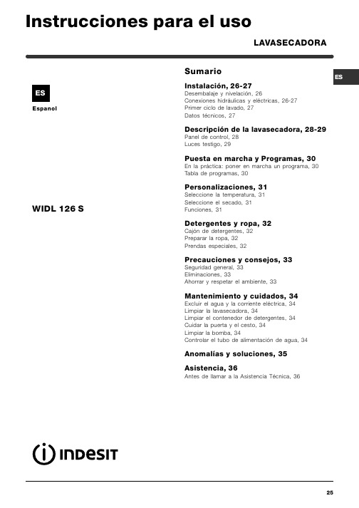
EspanolSumarioInstalación, 26-27Desembalaje y nivelación, 26Conexiones hidráulicas y eléctricas, 26-27Primer ciclo de lavado, 27Datos técnicos, 27Descripción de la lavasecadora, 28-29Panel de control, 28Luces testigo, 29Puesta en marcha y Programas, 30En la práctica: poner en marcha un programa, 30Tabla de programas, 30Personalizaciones, 31Seleccione la temperatura, 31Seleccione el secado, 31Funciones, 31Detergentes y ropa, 32Cajón de detergentes, 32Preparar la ropa, 32Prendas especiales, 32Precauciones y consejos, 33Seguridad general, 33Eliminaciones, 33Ahorrar y respetar el ambiente, 33Mantenimiento y cuidados, 34Excluir el agua y la corriente eléctrica, 34Limpiar la lavasecadora, 34Limpiar el contenedor de detergentes, 34Cuidar la puerta y el cesto, 34Limpiar la bomba, 34Controlar el tubo de alimentación de agua, 34Anomalías y soluciones, 35Asistencia, 36Antes de llamar a la Asistencia Técnica, 36LAVASECADORAWIDL 126 SInstrucciones para el usoEs importante conservar este manual para poderconsultarlo en cualquier momento. En caso de venta,de cesión o de traslado, verifique que permanezca junto con la lavasecadora para informar al nuevo propietario sobre el funcionamiento y brindar las correspondientes advertencias.Lea atentamente las instrucciones: ellas contienenimportante información sobre la instalación, el uso y la seguridad.Desembalaje y nivelaciónDesembalaje1. Desembale la lavasecadora.2. Controle que la lavasecadora no haya sufrido daños durante el transporte. Si estuviera dañada no la conecte y llame al revendedor.3. Quite los 4 tornillos de protección para el transporte y la arandela de goma con el corres-pondiente distanciador,ubicados en la parte posterior (ver la figura ).4. Cierre los orificios con los tapones de plástico suministrados con el aparato.5. Conserve todas las piezas: cuando la lavasecadora deba ser transportada nuevamente, deberán volver a colocarse.Los embalajes no son juguetes para los niños.Nivelación1. Instale la lavasecadora sobre un piso plano y rígido, sin apoyarla en las paredes, muebles ni en ningún otro aparato.2. Si el piso no estáperfectamente horizontal,compense las irregulari-dades desenroscando o enroscando los pies delanteros (véase la figura ); el ángulo deinclinación medido sobre la superficie de trabajo,no debe superar los 2º.Una cuidadosa nivelación brinda estabilidad a la máquina y evita vibraciones, ruidos y desplazamien-tos durante el funcionamiento. Cuando se instala sobre moquetas o alfombras, regule los pies para conservar debajo de la lavasecadora un espacio suficiente para la ventilación.Conexiones hidráulicas y eléctricasConexión del tubo de alimentación de agua1. Introduzca la junta A en el extremo del tubo de alimentación yenrósquelo a un grifo de agua fría con boca roscada de 3/4 gas (véase la figura ).Antes de conectarlo,haga correr el agua hasta que salga limpia.2. Conecte el tubo de alimentación a lalavasecadora enroscán-dolo en la toma de agua correspondiente ubica-da en la parte posterior arriba y a la derecha (véase la figura ).3. Verifique que el tubo no tenga pliegues ni estran-gulaciones.La presión de agua del grifo debe estar comprendi-da dentro de los valores contenidos en la tabla de Datos técnicos (ver la página del costado ).Si la longitud del tubo de alimentación no fuerasuficiente, diríjase a una tienda especializada o a un técnico autorizado.InstalaciónPanel de controlDescripción de la lavasecadoraCajón de detergentes: para cargar detergentes y aditivos (véase la pág. 32).Luces testigo: para seguir el estado de avance del programa de lavado.Si se seleccionó la función Delay Timer, indicarán el tiempo que falta para la puesta en marcha del programa (ver la pág. 29).Mando de SECADO: para seleccionar el secado deseado (ver la pág. 31).Botones de FUNCIÓN:para seleccionar las funcio-nes disponibles. El botón correspondiente a la función seleccionada permanecerá encendido.Mando de TEMPERATURA:para seleccionar la temperatura o el lavado en frío (ver la pág. 31).Botón de START/RESET:para poner en marcha los programas o anular las selecciones incorrectas. Luz indicadora de ENCENDIDO/PUERTA BLO-QUEADA:para saber si la lavasecadora está encen-dida y si la puerta se puede abrir (ver la pág. 29). Botón de ENCENDIDO/APAGADO: para encender y apagar la lavasecadora.Mando de PROGRAMAS:para elegir los progra-mas. Durante el programa el mando no se mueve.Botones deSECADOLuz indicadora dePuesta en marcha y ProgramasTabla de programasEn la práctica: poner en marcha un programa1.Encienda la lavasecadora pulsando el botón .algunos segundos, luego se apagarán y la luzindicadora de ENCENDIDO/PUERTA BLOQUEADA comenzará a centellear.2.Cargue la ropa y cierre la puerta.3.Seleccione el programa deseado con el mando de PROGRAMAS.4.Fije la temperatura de lavado (ver la pág. 31).5. Seleccione el secado si es necesario (ver la pág. 31).6.Vierta el detergente y los aditivos (véase la pág. 32).7.Ponga en marcha el programa pulsando el botón START/RESET.Para anular, mantenga presionado el botónSTART/RESET durante 2 segundos como mínimo.8.Al finalizar el programa, la luz indicadora de ENCEN-DIDO/PUERTA BLOQUEADA centelleará indicando que la puerta se puede abrir. Extraiga la ropa y deje la puerta semicerrada para permitir que el cesto seseque. Apague la lavasecadora pulsando el botón Notas-En el programa 9 es aconsejable no superar una carga de ropa de 3,5 kg.-En el programa 13 se aconseja no superar una carga de ropa de 2 kg.-Para la descripción del antiarrugas: consulte Plancha fácil, página siguiente. Los datos contenidos en la tabla tienen un valor indicativo.Programa especialDiario 30' (programa 11 para Sintéticos) fue estudiado para lavar prendas ligeramente sucias y en poco tiempo:dura sólo 30 minutos y de esa manera hace ahorrar energía y tiempo. Seleccionando el programa (11 a 30ºC)es posible lavar conjuntamente tejidos de distinto tipo (excluidas lana y seda), con una carga máxima de 3 kg.Se aconseja el uso de detergente líquido.PersonalizacionesCajón de detergentesEl buen resultado del lavado depende también de la correcta dosificación del detergente: si se excede la cantidad, no se lava de manera más eficaz, sino que se contribuye a encostrar las partes internas de la lavasecadora y a contaminar el ambiente.Extraiga el cajón dedetergentes e introduz-ca el detergente o eladitivo de la siguientemanera:cubeta 1: Detergente para prelavado (en polvo) cubeta 2: Detergente para lavado(en polvo o líquido)El detergente líquido se debe verter sólo antes de la puesta en marcha.cubeta 3: Aditivos (suavizante, etc.)El suavizante no se debe volcar fuera de la rejilla.No use detergentes para el lavado a mano ya que producen demasiada espuma.Preparar la ropaSubdivida la ropa según:- el tipo de tejido / el símbolo en la etiqueta.- los colores: separe las prendas de color y las blancas. Vacíe los bolsillos y controle los botones.No supere los valores indicados, referidos al peso de la ropa seca:Tejidos resistentes: max 5 kg.Tejidos sintéticos: max 2,5 kg.Tejidos delicados: max 2 kg.Lana: max 1 kg.¿Cuánto pesa la ropa?1 sábana 400/500 g1 funda 150/200 g1 mantel 400/500 g1 albornoz 900/1.200 g1 toalla 150/250 g Prendas especialesCortinas: pliéguelas y colóquelas dentro de una funda o de una bolsa de red. Lávelas solas sin superar la media carga. Utilice el programa 6 que excluye automáticamente el centrifugado. Cazadoras acolchadas con plumas y anoraks: si el relleno es de pluma de ganso o de pato, se pueden lavar en la lavasecadora. Poner las prendas del revés y realizar una carga máxima de 2-3 kg. repitiendo el enjuague una o dos veces y utilizando el centrifugado delicado.Lana: para obtener los mejores resultados, utilice un detergente específico y no supere 1 kg. de carga.Detergentes y ropa123Precauciones y consejosMantenimiento y cuidadosExcluir agua y corriente eléctricaCierre el grifo de agua después de cada lavado. De este modo se limita el desgaste de la instalación hidráulica de la lavasecadora y se elimina el peligro de pérdidas.Desenchufe la máquina cuando la deba limpiar y durante los trabajos de mantenimiento.Limpiar la lavasecadoraLa parte externa y las partes de goma se pueden limpiar con un paño embebido en agua tibia y jabón. No use solventes ni productos abrasivos.Limpiar el cajón de los detergentesExtraiga el contenedortirando hacia fuera (verla figura).Lávelo debajo del aguacorriente, esta limpiezase debe realizar fre-cuentemente.Cuidar la puerta y el cestoDeje siempre semicerrada la puerta para evitar que se formen malos olores.Limpiar la bombaLa lavasecadora posee una bomba autolimpiante que no necesita mantenimiento. Pero puede suce-der que objetos pequeños (monedas, botones) caigan en la precámara que protege la bomba, situada en la parte inferior de la misma.Verifique que el ciclo de lavado haya terminado y desenchufe la máquina.Para acceder a la precámara:1.quite el panel decobertura delantero dela lavasecadora con laayuda de un destornilla-dor (ver la figura);2.desenrosque la tapagirándola en sentidoantihorario (ver la figura);es normal que sevuelque un poco deagua;3.limpie con cuidado el interior;4.vuelva a enroscar la tapa;5.vuelva a montar el panel verificando, antes de empujarlo hacia la máquina, que los ganchos se hayan introducido en las correspondientes ranuras.Controle el tubo de alimentaciónde aguaControle el tubo de alimentación al menos una vez al año. Si presenta grietas o rozaduras se debe susti-tuir: durante los lavados, las fuertes presionespodrían provocar roturas imprevistas.No utilice nunca tubos ya usados.Anomalías y soluciones3536Antes de llamar a la Asistencia Técnica: Verifique si la anomalía la puede resolver solo (ver la pág. 35); Vuelva a poner en marcha el programa para controlar si el inconveniente fue resuelto; Si no es así, llame a la Asistencia técnica autorizada, al número de teléfono indicado en el certificado de garantía.No recurra nunca a técnicos no autorizados.Comunicar: el tipo de anomalía; el modelo de la máquina (Mod.); el número de serie (S/N ).Estas informaciones se encuentran en la placa que está fijada en la parte posterior de la lavasecadora.Asistencia 195043211.0110/2004 - Xerox Business Services。
CommScope LazrSPEED 低烟零有害分布纤维光缆(Z-DS系列)说明书
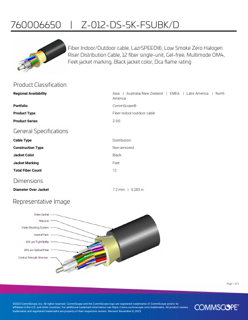
Page of 13Fiber Indoor/Outdoor cable, LazrSPEED®, Low Smoke Zero HalogenRiser Distribution Cable, 12 fiber single-unit, Gel-free, Multimode OM4,Feet jacket marking, Black jacket color, Dca flame ratingProduct ClassificationRegional AvailabilityAsia | Australia/New Zealand | EMEA | Latin America | North America PortfolioCommScope®Product TypeFiber indoor/outdoor cable Product Series Z-DSGeneral SpecificationsCable TypeDistribution Construction TypeNon-armored Jacket ColorBlack Jacket MarkingFeet Total Fiber Count 12DimensionsDiameter Over Jacket 7.2 mm | 0.283 inRepresentative ImageMechanical SpecificationsMinimum Bend Radius, loaded108 mm | 4.252 inMinimum Bend Radius, unloaded72 mm | 2.835 inTensile Load, long term, maximum400 N | 89.924 lbfTensile Load, short term, maximum1335 N | 300.12 lbfCompression22 N/mm | 125.623 lb/inCompression Test Method FOTP-41 | IEC 60794-1 E3Flex100 cyclesFlex Test Method FOTP-104 | IEC 60794-1 E6Impact 5.88 N-m | 52.042 in lbImpact Test Method FOTP-25 | IEC 60794-1 E4Strain See long and short term tensile loadsStrain Test Method FOTP-33 | IEC 60794-1 E1Twist10 cyclesTwist Test Method FOTP-85 | IEC 60794-1 E7Vertical Rise, maximum500 m | 1,640.42 ftOptical SpecificationsFiber Type OM4, LazrSPEED® 550 | OM4, LazrSPEED® 550Environmental SpecificationsInstallation temperature-30 °C to +60 °C (-22 °F to +140 °F)Operating Temperature-40 °C to +70 °C (-40 °F to +158 °F)Storage Temperature-40 °C to +75 °C (-40 °F to +167 °F)Cable Qualification Standards ANSI/ICEA S-104-696 | EN 187105 | Telcordia GR-20 (waterpenetration) | Telcordia GR-409EN50575 CPR Cable EuroClass Fire Performance DcaEN50575 CPR Cable EuroClass Smoke Rating s1aEN50575 CPR Cable EuroClass Droplets Rating d1EN50575 CPR Cable EuroClass Acidity Rating a2Environmental Space Low Smoke Zero Halogen (LSZH) | RiserFlame Test Listing NEC OFNR-ST1 (ETL) and c(ETL)IEC 60332-3 | IEC 60754-2 | IEC 61034-2 | UL 1666 | UL 168523Page ofFlame Test Method IEC 60332-3 | IEC 60754-2 | IEC 61034-2 | UL 1666 | UL 1685 Jacket UV Resistance UV stabilizedWater Penentration24 hWater Penentration Test Method FOTP-82 | IEC 60794-1 F5Environmental Test SpecificationsCable Freeze Test Method IEC 60794-1 F15Heat Age-40 °C to +85 °C (-40 °F to +185 °F)Heat Age Test Method IEC 60794-1 F9Low High Bend-40 °C to +70 °C (-40 °F to +158 °F)Low High Bend Test Method FOTP-37 | IEC 60794-1 E11Temperature Cycle-40 °C to +70 °C (-40 °F to +158 °F)Temperature Cycle Test Method FOTP-3 | IEC 60794-1 F1Packaging and WeightsCable weight49 kg/km | 32.926 lb/kftRegulatory Compliance/CertificationsAgency ClassificationCENELEC EN 50575 compliant, Declaration of Performance (DoP) availableCHINA-ROHS Below maximum concentration valueISO 9001:2015Designed, manufactured and/or distributed under this quality management systemREACH-SVHC Compliant as per SVHC revision on /ProductComplianceROHS CompliantUK-ROHSCompliantIncluded ProductsCS-5K-TB–LazrSPEED® 550 OM4 Bend-Insensitive MultimodeFiber* FootnotesOperating Temperature Specification applicable to non-terminated bulk fiber cablePage of33。
艾泰科技 HiPER ReOS 6.0 高级配置手册

HiPER ReOS 6.0 高级配置手册上海艾泰科技有限公司版权声明版权所有©2000-2006,上海艾泰科技有限公司,保留所有权利。
本文档所提供的资料包括URL及其他Internet Web站点参考在内的所有信息,如有变更,恕不另行通知。
除非另有注明,本文档中所描述的公司、组织、个人及事件的事例均属虚构,与真实的公司、组织、个人及事件无任何关系。
本手册及软件产品受最终用户许可协议(EULA)中所描述的条款和条件约束,该协议位于产品文档资料及软件产品的联机文档资料中,使用本产品,表明您已经阅读并接受了EULA中的相关条款。
遵守所生效的版权法是用户的责任。
在未经上海艾泰科技有限公司明确书面许可的情况下,不得对本文档的任何部分进行复制、将其保存于或引进检索系统;不得以任何形式或任何方式(电子、机械、影印、录制或其他可能的方式)进行商品传播或用于任何商业、赢利目的。
上海艾泰科技有限公司拥有本文档所涉及主题的专利、专利申请、商标、商标申请、版权及其他知识产权。
在未经上海艾泰科技有限公司明确书面许可的情况下,使用本文档资料并不表示您有使用有关专利、商标、版权或其他知识产权的特许。
艾泰®、UTT®文字及相关图形是上海艾泰科技有限公司的注册商标。
HiPER®文字及其相关图形是上海艾泰科技有限公司的注册商标。
此处所涉及的其它公司、组织或个人的产品、商标、专利,除非特别声明,归各自所有人所有。
产品编号(PN):0900-0062-001文档编号(DN):PR-PMMU-1107.07-PPR-CN-1.0A目录导读 (1)0.1 手册说明 (1)0.2 界面风格 (1)0.3 基本约定 (2)0.3.1 列表功能详解 (2)0.3.1.1 可编辑列表 (2)0.3.1.2 只读列表 (3)0.3.1.3 列表排序功能 (3)0.3.2 符号约定 (3)0.3.3 键盘操作约定 (4)0.3.4 其他表达约定 (4)0.4 出厂配置 (4)0.5 内容简介 (5)第1章产品概述 (8)1.1 关键特性 (8)1.2 主要特点 (8)1.3 VPN功能 (10)1.4 规格 (10)第2章硬件安装 (11)2.1 安装准备 (11)2.2 安装流程 (11)4540NB/4240NB安装步骤 (12)2.3 HiPER4520NB/4520VF/3320NB/3300NB/3300VF安装步骤 (15)2.4 HiPER4510NB/3310NB/3300NBs安装步骤 (18)2.5 HiPER3100VF安装步骤 (21)2.6 HiPER第3章快速向导 (23)3.1 配置正确的网络设置 (23)3.2 快速向导 (24)3.2.1 登录密码设置 (25)3.2.2 系统时钟配置 (26)3.2.3 上网接入方式设置 (26)3.2.4 上网接入线路配置 (27)3.2.4.1 上网接入线路配置的注意事项 (27)3.2.4.2 PPPoE拨号上网配置 (27)3.2.4.3 固定IP接入配置 (29)3.2.4.4 动态IP接入配置 (30)3.2.5 小结 (30)第4章基本配置 (31)4.1 线路配置 (31)4.1.1 线路连接信息列表 (31)4.1.1.1 参数涵义 (32)4.1.1.2 列表功能 (33)4.1.1.3 PPPoE拨号接入线路的拨号与挂断 (34)4.1.1.4 动态IP接入线路的更新与释放 (34)4.1.2 线路配置 (35)4.1.2.1 PPPoE拨号上网配置 (36)4.1.2.2 固定IP接入配置 (38)4.1.2.3 动态IP接入配置 (39)4.1.2.4 删除线路 (39)4.1.3 相关的缺省路由 (40)4.2 线路组合 (41)4.2.1 线路组合功能介绍 (41)4.2.1.1 线路组合方式 (41)4.2.1.2 线路检测机制 (41)4.2.1.3 线路检测方法 (42)4.2.2 多线路负载均衡功能介绍 (43)4.2.2.1 根据源IP地址指定优先线路 (43)4.2.2.2 根据线路带宽合理分配流量 (43)4.2.2.3 提供两种流量分配规则 (44)4.2.3 线路组合通用设置 (44)4.2.3.1 所有线路负载均衡 (45)4.2.3.2 部分线路负载均衡,其余备份 (45)4.2.4 线路检测及权重配置 (46)4.2.5 线路组合信息列表 (47)4.2.5.1 部分参数涵义 (48)4.2.5.2 列表功能 (48)4.2.6 配置线路组合 (48)4.2.6.1 线路组合的配置顺序 (48)4.2.6.2 线路组合通用设置配置步骤 (49)4.2.6.3 线路检测及权重配置步骤 (49)4.2.7 相关的检测路由 (49)4.3 DHCP和DNS服务器 (50)4.3.1 DHCP服务配置 (50)4.3.2 DHCP地址池使用信息 (51)4.3.3 配置DHCP服务器 (52)4.3.4 DHCP手工绑定配置 (52)4.3.5 DHCP手工绑定列表 (53)4.3.6 自定义DHCP手工绑定 (53)4.4 接口配置 (54)4.4.1 接口配置 (54)4.4.2 接口配置信息列表 (55)4.4.4 配置第二个IP地址 (55)4.4.5 配置MAC地址 (56)4.4.6 配置ARP代理 (56)4.4.7 配置以太网工作模式 (56)4.5 DDNS配置 (57)4.5.1 申请DDNS帐号 (57)4.5.2 配置DDNS服务 (59)4.5.3 DDNS状态 (59)4.5.4 DDNS验证 (60)4.6 时间段配置 (62)4.6.1 时间段配置 (62)4.6.2 时间段列表 (63)4.6.3 自定义时间段 (64)4.6.4 时间段配置实例 (64)第5章系统管理 (67)5.1 管理员配置 (67)5.1.1 WEB界面管理员配置 (67)5.1.2 管理员信息列表 (68)5.1.3 自定义管理员 (68)5.2 时钟管理 (69)5.3 软件升级 (70)5.3.1 显示和保存当前运行软件 (70)5.3.2 软件升级 (70)5.4 配置管理 (72)5.4.1 保存当前配置 (72)5.4.2 导入配置 (72)5.4.3 恢复出厂配置 (72)5.4.4 重新启动设备 (73)5.5 WEB服务器 (74)5.6 SNMP配置 (75)5.7 SYSLOG配置 (76)5.8 远程管理 (77)第6章高级配置 (78)6.1 组管理 (78)6.1.1 工作组配置 (78)6.1.2 工作组列表 (79)6.1.3 自定义工作组 (79)6.1.4 工作组配置实例 (79)6.2 业务管理 (81)6.2.1 业务管理功能介绍 (81)6.2.1.1 IP过滤、URL过滤及关键字过滤 (81)6.2.1.2 工作组、个人用户及IPSSG组 (82)6.2.1.4 业务策略的类型及排列顺序 (83)6.2.1.5 业务策略的执行顺序 (84)6.2.2 业务策略配置 (84)6.2.2.1 业务策略配置——IP过滤 (84)6.2.2.2 业务策略配置——URL过滤 (86)6.2.2.3 业务策略配置——关键字过滤 (87)6.2.2.4 个人用户业务策略的配置方法及注意事项 (88)6.2.3 业务管理全局配置 (88)6.2.4 业务策略信息列表 (89)6.2.5 自定义业务策略 (89)6.2.6 业务策略配置实例 (90)6.2.6.1 工作组策略配置实例 (90)6.2.6.2 个人用户策略配置实例 (94)6.2.6.3 源端口的应用实例 (95)6.3 NAT和DMZ配置 (97)6.3.1 NAT功能介绍 (97)6.3.1.1 NAT简介 (97)6.3.1.2 NAT地址空间 (97)6.3.1.3 三种NAT类型 (97)6.3.1.4 NAT静态映射和虚拟服务器(DMZ主机) (97)6.3.1.5 上网线路、NAT规则与NAT静态映射的关系 (98)6.3.2 系统保留NAT规则 (98)6.3.3 NAT与多线路负载均衡功能 (100)6.3.3.1 概述 (100)6.3.3.2 根据源IP地址指定优先通道 (100)6.3.3.3 根据线路带宽合理分配流量 (100)6.3.3.4 两种流量分配规则 (100)6.3.3.5 NAT规则的匹配次序 (101)6.3.4 NAT全局配置 (101)6.3.5 NAT规则 (102)6.3.5.1 NAT规则配置 (102)6.3.5.2 NAT规则列表 (104)6.3.5.3 自定义NAT规则 (104)6.3.5.4 NAT规则配置的注意事项 (105)6.3.5.5 NAT规则配置实例 (106)6.3.6 NAT静态映射 (109)6.3.6.1 NAT静态映射配置 (109)6.3.6.2 NAT静态映射列表 (110)6.3.6.3 自定义NAT静态映射 (110)6.3.6.4 NAT静态映射配置实例 (111)6.4 路由配置 (113)6.4.1 静态路由 (113)6.4.1.1 静态路由概述 (113)6.4.1.3 静态路由配置 (115)6.4.1.4 路由信息列表 (116)6.4.1.5 自定义静态路由 (117)6.4.2 静态路由策略库 (118)6.4.2.1 静态路由策略库概述 (118)6.4.2.2 静态路由策略库配置 (119)6.4.2.3 如何设置静态路由策略库 (120)6.4.2.4 如何更新静态路由策略库 (121)6.5 IP/MAC绑定 (122)6.5.1 IP/MAC绑定功能介绍 (122)6.5.1.1 IP/MAC绑定概述 (122)6.5.1.2 IP/MAC绑定的工作原理 (122)6.5.2 IP和MAC绑定配置 (124)6.5.3 IP/MAC绑定全局配置 (125)6.5.4 IP/MAC绑定信息列表 (125)6.5.5 自定义IP/MAC绑定条目 (126)6.5.6 配置上网“白名单”和“黑名单” (126)6.5.6.1 配置上网“白名单” (127)6.5.6.2 配置上网“黑名单” (127)6.6 特殊功能 (130)6.6.1 快速转发 (130)6.6.1.1 快速转发功能概述 (130)6.6.1.2 快速转发配置 (130)6.6.2 虚拟局域网 (130)6.6.2.1 虚拟局域网功能概述 (130)6.6.2.2 虚拟局域网配置 (131)6.6.3 端口镜像 (131)6.6.3.1 端口镜像功能概述 (131)6.6.3.2 端口镜像配置 (131)6.6.3.3 端口镜像应用实例 (132)6.7 DHCP配置 (133)6.7.1 DHCP简介 (133)6.7.1.1 DHCP介绍 (133)6.7.1.2 DHCP的工作原理 (133)6.7.1.3 DHCP数据包的类型 (134)6.7.2 HiPER的DHCP功能概述 (135)6.7.2.1 DHCP服务器 (135)6.7.2.2 DHCP客户端 (137)6.7.2.3 DHCP中继 (137)6.7.2.4 自定义选项(Raw Option) (138)6.7.3 DHCP客户端 (138)6.7.3.1 DHCP客户端配置 (139)6.7.3.2 DHCP客户端信息列表 (140)6.7.4 DHCP服务器 (141)6.7.4.1 DHCP服务器全局配置 (141)6.7.4.2 DHCP地址池配置 (141)6.7.4.3 DHCP地址池信息列表 (143)6.7.4.4 自定义DHCP地址池 (144)6.7.4.5 DHCP手工绑定配置 (145)6.7.4.6 DHCP手工绑定列表 (146)6.7.4.7 自定义DHCP手工绑定 (147)6.7.5 DHCP中继 (147)6.7.5.1 DHCP中继配置 (147)6.7.5.2 DHCP中继信息列表 (148)6.7.5.3 配置DHCP中继 (148)Option (149)6.7.6 Raw6.7.6.1 Raw Option配置 (149)6.7.6.2 Raw Option信息列表 (150)6.7.6.3 自定义Raw Option (150)6.7.7 DHCP典型配置实例 (150)6.7.7.1 DHCP服务器典型配置实例 (150)6.7.7.2 DHCP客户端典型配置实例 (154)6.7.7.3 DHCP中继典型配置实例 (155)6.7.7.4 Raw Option典型配置实例 (156)6.7.7.5 综合应用实例 (157)6.8 UPnP配置 (161)6.8.1 启用UPnP (161)NAT映射列表 (161)6.8.2 UPnP第7章系统状态 (163)7.1 用户统计 (163)7.2 NAT统计 (166)7.2.1 NAT状态信息列表 (166)7.2.2 NAT统计信息列表 (167)7.3 DHCP统计 (170)7.3.1 DHCP地址池使用信息列表 (170)7.3.2 DHCP服务器统计信息列表 (171)7.3.3 DHCP冲突信息列表 (172)7.3.4 DHCP客户端统计信息列表 (173)7.3.5 DHCP中继统计信息列表 (174)7.4 接口统计 (175)7.5 路由和端口信息 (177)7.5.1 路由表信息 (177)7.5.2 端口信息 (179)7.6 系统信息 (180)7.6.1 页面刷新功能 (180)7.6.2 系统运行时间 (180)7.6.4 系统版本信息 (181)7.6.5 系统告警信息 (181)7.6.6 系统历史记录 (182)第8章上网监控 (184)8.1 查询条件 (184)8.2 查询结果列表 (185)8.3 查询实例 (186)8.3.1 查询局域网IP地址为200.200.200.87/24的用户当前上网行为 (186)8.3.2 查询局域网内目前访问的用户 (187)8.3.3 查询局域网内目前使用MSN的用户 (187)8.3.4 查询局域网内目前使用WAN2口IP地址上网的信息 (188)8.3.5 查询局域网内目前使用默认线路上网的信息 (189)第9章带宽业务 (191)9.1 带宽信用管理 (191)9.1.1 带宽信用管理功能概述 (191)9.1.1.1 概述 (191)9.1.1.2 IP RATE功能 (191)9.1.1.3 CBT DRR功能 (192)9.1.1.4 工作流程 (193)9.1.2 带宽信用管理配置 (193)9.1.3 带宽信用管理信息列表 (194)9.1.4 配置方法及实例 (195)9.1.4.1 相关概念 (195)9.1.4.2 如何设置“最大下载速率”和“最大上传速率” (195)9.1.4.3 如何设置“最小速率” (196)9.1.4.4 如何设置“管制时间” (196)9.1.4.5 如何恢复信用 (197)第10章安全配置 (198)10.1 基本选项 (198)10.2 用户管理 (200)10.2.1 用户管理信息列表 (200)10.2.2 用户信息配置 (201)10.2.2.1 个性化配置概述 (201)10.2.2.2 用户信息配置 (202)10.2.2.3 用户当前状态 (204)10.3 策略库 (205)10.3.1 策略库概述 (205)10.3.2 策略库信息列表 (205)10.3.3 策略库版本检查 (206)10.3.4 导入策略库 (206)10.4 ARP欺骗防御 (208)10.4.2 动态ARP表管理 (209)10.4.3 如何防止ARP欺骗攻击 (209)附录A 配置局域网中的计算机 (210)附录B FAQ (216)1. ADSL用户如何上网? (216)2. 固定IP接入用户如何上网? (217)3. 动态IP(Cable Modem)接入用户如何上网? (218)4. 如何将HiPER恢复到出厂配置? (219)5. 如何使用CLI“急救模式”? (226)6. IP/MAC绑定、工作组与业务管理 (230)7. 如何发现使用带宽最大的用户? (233)8. 如何诊断蠕虫病毒或者黑客攻击造成的HiPER使用异常的故障? (234)9. 如何实现允许响应外部PING? (236)附录C 常用IP协议 (237)附录D 常用服务端口 (238)附录E 图索引 (242)附录F 表索引 (246)导读提示:为了达到最好的使用效果,建议将Windows Internet Explorer浏览器升级到6.0以上版本。
HIOS电动螺丝刀18A HIOS 电动螺丝刀 使用说明书 VZ 系列
HIOS 电动螺丝刀使用说明书 VZ 系列系列构成使用电压 AC 220V(2018年4月現在)制造商 株式会社HIOS 总公司 邮编270-2223 日本国千叶县松户市秋山1-16-5TEL :81-47-392-2001 F AX :81-47-392-7778VZ-1812、 VZ-1812PS 小系列 VZ-3007、 VZ-3007PS 小系列 VZ-4504、 VZ-4504PS 小系列使用说明书NO.ET-A024●为了使您掌握所选机种的使用方法及安全操作,请务必阅读随机附上的使用说明书,正确使用本产品。
●本安全操作注意规程属于一般安全性方面的说明书。
为安全使用请仔细阅读有关内容。
●请绝对不要在指定用途以外使用电动螺丝刀及变压器。
●要时常整理、整顿作业现场的周围。
保持便于操作的生产作业环境。
●电动螺丝刀等电动工具要避免阳光直射。
●所使用的电压必须符合电动螺丝刀本体制造标牌上所指定的电压额定值。
●如果使用指定以外的电压的话机体将会发生故障诱发触电事故。
有关作业现场的注意事项!注意 !警告 1.为安全使用●为了能安全使用本产品、请必须按照下面注意事项及警告使用产品。
●请不要以使用说明书指定以外的目的使用电动螺丝刀或变压器。
是引起故障或事故的原因。
●使用变压器时请必须设置防漏电跳闸和安全跳闸。
●请必须接上变压器以及HIOS 电动螺丝刀的接地线以确保安全。
●本产品为在220V 电压下使用的产品,切勿在其他电压条件下使用。
●本型号的电动螺丝刀为主机电源线一体型,任何部分如有异常,请不要自行拆开主机,而应立即停止使用并交给厂家或经销商修理。
●更换碳刷时,由于磨掉的碳粉致使绝缘效果降低,故请交给厂家或经销商进行维护检查。
一般每使用100万次或者每使用1年要做一次检查。
●请绝对避免与指定电压以外的电源进行连接。
万一发生触电事故或受伤等、本公司不承担责任。
●不要用湿手或带油的手操作电动螺丝刀。
是引起感电事故或受伤的原因。
zimbra_6_0_12_GA_Release_Notes
ZCA 6.0.121Zimbra Collaboration Suite Appliance 6.0.12 Release NotesThis release notes cover the following topics:•Major Features for Zimbra Appliance on page 1•System Requirements on page 2•Licensing on page 3•Update Instructions on page 4•Installing Zimbra Appliance on page 4•Known Issues on page 4•Product Documentation on page 5•Bug Reporting on page 6Major Features for Zimbra ApplianceZimbra is the leader in open source, Web 2.0 collaboration and messagingsoftware for enterprises, service providers, educational institutions, andgovernment agencies. The Zimbra Collaboration Suite Appliance (ZCA) isyour email and collaboration cloud delivered as a virtual appliance for faster provisioning and easier administration than traditional solutions.Major Features•Zimbra Email Server•Zimbra Advanced Email client•Zimbra Address Book•Zimbra Calendar•Zimbra Document management and Tasks•Zimbra Mobile web client•Zimbra Mobile sync•Simplified deployment options for your virtual environments.•Simplified task based administration console.Deployment options for VMware environments•VMDK and OVF based deployment options•Simplified initial service configuration•Automatic configuration of new storage and memory allocations on reboot.Task based administration console•Dashboard with task based management features.•Account, Distribution List, Resource, Domain and Alias creation andmanagement•Profiles for feature and policy based administration•Mobile device policy management•Color scheme configuration options of the Zimbra Web Client interface.•Advanced tools for migration and interoperability•Exchange migration tools.•Exchange interoperability for Free/Busy, Global Address List andExternal authentication•LDAP interoperability for Global Address List and Externalauthentication•Self-signed and commercial SSL certificate management•Zimbra license management•Service status overviews•Service level control with status•Diagnostic tools to log file downloadsSystem Requirements•DNS with both A and MX records for sending and receiving mail•Server hardware capable of running 64-bit virtual machines•5GB free disk space required for the Zimbra Appliance software forevaluation and testing•20GB free disk space required for production environments using thickprovisioning disk file•Additional disk space for mail storage.When you add a new disk, choose “virtual” as the compatibility mode. Ifyou do not do this the new disk is not included in the virtual machinesnapshot of ZCA.•Server and storage hardware listed on the VMware vSphere HardwareCompatibility List (HCL)2 ZCA 6.0.12Zimbra Collaboration Suite Appliance 6.0.12 Release Notes •VMware VSphere 4.0 or laterDeployment Configuration SizingWhen Zimbra Appliance is installed, you select the deployment configurationthat matches your requirements.•Trial. For Zimbra Appliance deployments in a non-production labenvironment for up to 50 accounts, requires 1 vCPU and 2 GB RAM.•Midsize. For Zimbra Appliance deployment with 500 or less accounts provisioned, requires 2 vCPUs and 4 GB RAM.•Large. For Zimbra Appliance deployment with up to 1000 users. Requires2 vCPUs and 8 GB RAM.This sizing is the disk requirements for the installation only. Additional diskspace is required for account’s mail storage and collaboration folders.Backing Up With VMware Data RecoveryIn order to take snapshots (using VDR) of the Zimbra Appliance, the “VMFSblock size” should follow guidelines given at/selfservice/microsites/search.do?language=en_US&cmd=displayKC&externalId=1003565 .In addition, there are hard and soft requirements on VMFS block size. That is1.The file block size requirement for the Zimbra Appliance being backed up isa hard requirement enforced by ESX to be able to snapshot the VM.2.The file block size requirement for the VDR appliance is a soft requirement.VDR will not fail it is not on a datastore with the same large block size asthe Zimbra Appliance being backed up. If the block size is different, it willnot be able to back up the VM as efficiently using hotadd and will have to bebacked up over the network.LicensingLicense RequirementsA trial license and a regular license are available.•Trial. This license is automatically installed when you install Zimbra Appliance. The trial license allows you to create up to 50 users. It expires in60 days.•Regular. You must register with Zimbra to obtain a Zimbra Appliance regular license. This license is valid for a specific Zimbra Applianceinstallation and is encrypted with the number of Zimbra accounts you havepurchased, the effective date of the license and the expiration date of thelicense.ZCA 6.0.12 3Update InstructionsBACKUP BEFORE YOU BEGIN TO UPDATE!You do not need to stop the services before updating ZCA. The updateprocess automatically stops and starts the services as required for the update.1.Log into the administration console and click the Update tab.2.On the Update Status page that opens, click Details.... The latest updateinformation is displayed.Open a browser and type the URL to the ZCA administration console.Select the Update tab. This will be used when the update is complete instep 4.3.Click Install Updates in the Actions column.The update process begins. This may take a while. You cannot access theZCA management URL while the update is in progress.4.In the ZCA window opened as described in step 2, when the update iscomplete, this window displays System reboot is required to complete theupdate.Reboot the virtual machine.5.When the virtual machine has rebooted, close the confirmation dialog andopen the browser window and enter the ZCA management URL to log in.6.In the Status tab, click Begin the update now. A progress bar indicates theupdate progress.7.When Configuration Complete. Continue... is displayed in the Status tab,click Continue... . The ZCA server is restarted.8.To return to the administration console, enter the ZCA URL to log in. Thenew Zimbra version displays in the Zimbra Status tab and all servicesshould be running.Installing Zimbra ApplianceDownload the Zimbra Appliance Set Up Guide pdf for the set up directions.Known IssuesZimbra engineering has identified a number of issues with the software, andwe are actively working to resolve them. Following are the issues that aremost likely to occur. All known bugs are listed in Zimbra’s Bugzilla database,available on the Zimbra web site, at .4 ZCA 6.0.12Zimbra Collaboration Suite Appliance 6.0.12 Release Notes General Known Issuesicon and the administrator icon should neverProduct Documentation•Zimbra Appliance Set Up Guide. This guide describes prerequisites, and how to download and install the ZCA OVF package in the VMware® virtualmachine environment.•Zimbra Appliance Administrator’s Guide. This guide describes the Zimbra Appliance features and functionality, including how to create accounts inZCA.•Migration Wizard for Exchange Install Guide. Refer to this documentation if you are migrating users from Microsoft Exchange to Zimbra Appliance.•Administration Console Help. The Help covers how to perform tasks from the administration console.ZCA 6.0.12 5•Zimbra Web Client Help. The ZWC Help explains the features available from the Zimbra Web Client.Bug ReportingIf you encounter problems with this software, go to to submit a bug report. Make sure to provide enough detail so that the bugcan be easily duplicated. Also, to discuss issues and this software in general,please visit our community forums at /forums.-----------------------------------------------------------------------------------------------Copyright © 2011 Zimbra and VMware, Inc. All rights reserved.6.0.12 Zimbra Appliance Release Notes4/20116 ZCA 6.0.12。
- 1、下载文档前请自行甄别文档内容的完整性,平台不提供额外的编辑、内容补充、找答案等附加服务。
- 2、"仅部分预览"的文档,不可在线预览部分如存在完整性等问题,可反馈申请退款(可完整预览的文档不适用该条件!)。
- 3、如文档侵犯您的权益,请联系客服反馈,我们会尽快为您处理(人工客服工作时间:9:00-18:30)。
TM July 1997
HIP0060
1.5A, 50V Quad Low Side Power Driver with Serial Bus Control and Fault Protection
FN 4045 1-888-INTERSIL or 321-724-7143|Intersil (and design) is a trademark of Intersil Americas Inc.
Absolute Maximum Ratings Thermal Information
Max Output Voltage, V OUT (Note 2). . . . . . . . . . . . . . . . . . . . . V OC Max Output Load Current, I LOAD (Per Output, Note 3) . . . . . . . .I CL Logic Input Voltage. . . . . . . . . . . . . . . . . . . . . . . . . . . . . -0.3V to 7V Logic Supply Voltage, V DD. . . . . . . . . . . . . . . . . . . . . . -0.3V to +7V Operating Conditions
Ambient Temperature Range . . . . . . . . . . . . . . . . -40o C to 125o C Junction Temperature Range . . . . . . . . . . . . . . . . -40o C to 150o C Thermal Resistance (Typical, Notes 1, 4)θJA (o C/W) SOIC - PC Board Mount, Min. Copper . . . . . . . . . . 60 SOIC - PC Board Mount, 2 sq. in. Copper . . . . . . . . 35 Maximum Storage Temperature Range -55o C to 150o C
Maximum Lead Temperature (Soldering 10s). . . . . . . . . . . . .300o C (SOIC - Lead Tips Only)
CAUTION: Stresses above those listed in “Absolute Maximum Ratings” may cause permanent damage to the device. This is a stress only rating and operation of the device at these or any other conditions above those indicated in the operational sections of this specification is not implied.
NOTES:
1.θJA is measured with the component mounted on an evaluation PC board in free air.
2.The MOSFET Output Drain is internally clamped with a Drain-to-Gate zener diode that turns on the MOSFET; holding the Drain at the
Output Clamp voltage V OC.
3.The output drive is protected by an internal current limit. The I CL over-current limiting threshold parameter specification defines the max-
imum current. The maximum current with all outputs ON may be further limited by dissipation.
4.Device dissipation is based on thermal resistance capability of the package in a normal operating environment. The junction to ambient
thermal resistance of 60o C/W is defined here as a PC Board mounted device with minimal copper. With approximately 2 square inches of copper area as a heat sink, it is practical to achieve 35o C/W thermal resistance. Further reduction in the thermal resistance can be achieved with additional PC Board Copper ground area or an external heat sink structure next to the ground leads at the center of the package.
Electrical Specifications V DD = 4.5V to 5.5V, V SS = 0V, T A = -40o C to 125o C; Unless Otherwise Specified PARAMETER SYMBOL CONDITIONS MIN TYP MAX UNITS OUTPUTS DRIVERS (DR0 TO DR7)
Output Channel Resistance r DSON I OUT = 0.5A--0.8ΩOver-Current Limiting Threshold I CL 1.5- 3.5A Output Clamping Voltage V OC405060V Output Clamping Energy E OC1ms Single Pulse Width, T A = 25o C,
(Refer to Figure 3 for SOA Limits).
-85-mJ Output OFF Leakage Current I LK V OUT = 14.5V--180µA Open-Load Fault Threshold R OLD V OUT = 14.5V, Output Off4-200kΩOutput Rise Time t R R L = 30Ω, V OUT = 14.5V1-12µs Output Fall Time t F R L = 30Ω, V OUT = 14.5V1-12µs Turn-On Delay t ON R L = 30Ω, V OUT = 14.5V--12µs Turn-Off Delay t OFF R L = 30Ω, V OUT = 14.5V--12µs POWER SUPPLY
Power On Reset Threshold V DD(POR) 3.2- 4.4V
V DD Logic Supply Current I DD All Outputs ON or OFF--10mA LOGIC INPUTS (INx, SI, SCK, RST, CS)
High Level Input Voltage V IH0.7xV DD--V
Low Level Input Voltage V IL--0.2xV DD V Input Hysteresis V ILHYS0.8--V High Output Voltage, SO, INT V OL Current Sink = 1.6mA --0.4V
Low Output Voltage, SO V OH Current Source = -0.8mA V DD-0.8--V Input Pull-Down Current, INx I INPD75-250µA Reset Input Pull-Up Current, RST I RPU20-120µA。