一种高性能精密凸轮CAD/CAM系统
平面盘形凸轮CAD/CAM系统的研究
要求和制造精度要求。 计算机辅助设计与制造在凸轮机构设
案。目前它是 CD A 技术应用领域内的一个重要的、 而且有待
计中的应用, 将大大改善凸轮设计和制造的精度问题。 因此,
开发有效的凸轮 CDCM A/A 系统对 CDCM A/A 技术在凸轮机构
中的应用有重要意 义 。本文根据模 块化设计思想 , Vs- 在 iu aBsc的语 言环境下,采用 面向对象的程序设计 方法, lai 研 究开发了平面盘形 凸轮 CDC ̄ A/ A 系统 。
1 平面盘形 凸轮 C / AM 系统设计的功能要求 ADC
进一步研究的课题。在图形参数化中, 图形编程是建立在参
数驱动机制、 约束联动和驱动树基础上的, 利用参数驱动机
制对图形数据进行操作, 由约束联动和驱动树控 制驱动机制 的运行 。绘 图者不仅可以定义 图形结构, 还能控 制参数化过 程, 就像 用计算机 语言编程 一样, 定义数据 、 控制程序流程 。
算凸轮的理论轮廓线、实际轮廓线及刀具加工中心坐标点、 校 核压力角和最 小曲率半径, 对压力角和 曲率半径不满足要
求 的则修改参数 重新计算 。 Ii . 参数化设计 参数化设计是- f新兴学科, - ] 是计算机 图形学 、A/ A CDC ̄ 的重要研究内容之一 , 它主要描述 了一种相 , VsaBsc的语言环境下 , 本 在 i lai u 采用面 向对象的程序设计方法 , 开发 出了平 面盘形凸轮
CAD-CAM系统
CAD/CAM技术自从20世纪60年代产生以来,得到了快速发展,在制造业的应用也日益广泛,所产生的经济效益是巨大的,目前CAD/CAM技术已形成了上百种的商用软件系统。
按照系统功能的大小可分为大型、中型和小型CAD/CAM系统。
(1)大型CAD/CAM系统这类系统采用面向产品全生命周期的建摸技术,具有基于工程数据库的企业级产品数据管理(PDM)功能,提高工程工作站或高性能微机组成的客户机/服务器(C/S)的网络系统,支持设计群体小组的协同设计工作模式。
大型CAD/CAM系统功能强大,具备设计、分析、制造等产品制造全流程数字化功能,工程应用性好。
目前有代表的系统有美国PTC公司的产品Pro/Engineer系统,法国达索(Dassault)公司开发的CATIA系统,美国UGS公司的产品Unigraphics(UG)系统,美国SDRC公司开发I-DEAS系统,它们占据着目前世界上CAD/CAM 市场份额的70%以上。
(2)中型CAD/CAM系统这类系统提供工作在微机上的、功能完善的产品设计、装配、工程图、分析、加工等数字化坏境,具备参数化特征造型技术,系统应用方便、高效,为大多数中小型企业所欢迎。
代表的系统有生信国际有限公司推出的SolidWorks、以色列Cimatron公司的Cimatron、UGS/SDRC公司的SolidEdge、北航海尔软件有限公司推出的CAXA实体设计/制造工程师系统等。
(3)小型CAD/CAM系统这类系统工作在微机上,具有完善的二维绘图功能和简单的数控加工代码生成功能,在小型企业普遍应用。
代表作有美国Autodesk 公司的AutoCAD系统、北京北航海尔软件有限公司 CAXA电子图板/线切割系统、武汉开目公司的开目CAD系统等。
工程机械CAD_CAM课后习题答案

⼯程机械CAD_CAM课后习题答案第⼀章概述1.简述产品设计制造的⼀般过程。
答:CAD/CAM系统是设计、制造过程中的信息处理系统,它主要研究对象描述、系统分析、⽅案优化、计算分析、⼯艺设计、仿真模拟、NC编程以及图形处理等理论和⼯程⽅法,输⼊的是产品设计要求,输出的是零件的制造加⼯信息。
2.简述CAD/CAM技术的概念、狭义和⼴义CAD/CAM技术的区别与联系。
答:CAD/CAM技术是以计算机、外围设备及其系统软件为基础,综合计算机科学与⼯程、计算机⼏何、机械设计、机械加⼯⼯艺、⼈机⼯程、控制理论、电⼦技术等学科知识,以⼯程应⽤为对象,实现包括⼆维绘图设计、三维⼏何造型设计、⼯程计算分析与优化设计、数控加⼯编程、仿真模拟、信息存贮与管理等相关功能。
区别:⼴义的CAD/CAM技术,是指利⽤计算机辅助技术进⾏产品设计与制造的整个过程,及与之直接和间接相关的活动;狭义的CAD/CAM技术,是指利⽤CAD/CAM系统进⾏产品的造型、计算分析和数控程序的编制联系:⼴义的CAD/CAM技术包容狭义的CAD/CAM技术3.传统的设计制造过程与应⽤CAD/CAM技术进⾏设计制造的过程有何区别与联系?答:区别:传统的设计与制造⽅式是以技术⼈员为中⼼展开的,,产品及其零件在加⼯过程中所处的状态,设计、⼯艺、制造、设备等环节的延续与保持等,都是由⼈⼯进⾏检测并反馈,所有的信息均交汇到技术和管理⼈员处,由技术⼈员进⾏对象的相关处理。
以CAD/CAM技术为核⼼的先进制造技术,将以⼈员为中⼼的运作模式改变为以计算机为中⼼的运作模式,利⽤计算机存贮量⼤、运⾏速度快、可⽆限期利⽤已有信息等优势,将各个设计制造阶段及过程的信息汇集在⼀起,使整个设计制造过程在时间上缩短、在空间上拓展,与各个环节的联系与控制均由计算机直接处理,技术⼈员通过计算机这⼀媒介实现整个过程的有序化和并⾏化。
联系:制造过程的各个环节基本相同。
4.简述我国CAD/CAM技术发展的过程与特点。
CAD/CAM技术在凸轮设计与加工中的应用

hp/w . s .m环球市场 t: we 8c t/ w m 6o 信息导报
影 od 学生心理健康 的因素分析 P  ̄ ]
马 丽 娜 ( 山县 党 岔 镇 马 坊 小 学 陕 西横Biblioteka 山 7 9 1 ) 横 1 12
基于小学生心理健康教育 的需要 , 我于 2 1 年 4月对本校一 01 3 教 师是影响小学 生心理健康的 因素 . 至六年级共 2 1名学生进行了小学生心理健康现状调查 ,调查结 3 有一些教师在学生心理发展过程中,有意无意产生许 多不 良 果对我们 了解农村小学生心理健康现状 , 把握其心理动态 , 分析心 影响。一些教师的种种不健康心理 ,在平时的工作和与学生接触 理 问题成 因, 寻找合理的教育对策提供 了依据。 从 卷调查的总体 的过程 中, 就会通过言语、态度 、行为等方面表现出来。例如 : 驱 结果上看 ,心理健康的小学生占 7 . 这说明大部分小学生心理 赶学生出课堂 ,并称有你无我 ,有我无你 ;有的教 师对学生讽刺 30 %, 健康状况良好。 存在心理健康偏离 的小学生为 2 .%, 7 0 其中有 明显 挖苦、嘲笑贬低 ,各种过头话或者错误的批评 。这些都极易使学 心理 问题 的学生占 5 %,说 明出现心理 问题的小学生多数为轻度 生 产 生 反感 、抵 触 的 心理 ,久而 久 之 ,学 生就 会 产 生逆 反 心理 。 . 0 心理偏差 , 只要老师和家长及时发现并予以矫正就可以恢复健康。 有的老师在教育学生时 ,缺 乏必要的热情 ,更谈不上激情。 1 .家庭 是影响小 学生心理健康 的因素 还有些教师经常体罚 或变相体罚学生 ,这些都会导致这部分学生 祖祖 辈辈都是农民 , 自己甚至 家族的希望寄托在孩子身上 , 特别是学困生强烈不满。不仅将不满与怨恨对着老师,而且还 可 把 通过读书脱离农村,光宗耀祖 。他们对孩子爱得过分 ,照顾过度 , 能将不满和怨恨撒 向其他学生。 期望过高。另一方面 ,在孩子 的学业上又加大了砝码 ,回家什么 我 曾做 过一 次调查 ,小学生心 目中的好老师应该具 备下面的 活也不让干 ,电视不让看 ,不让玩 ,只让学 习;教辅用书、过关 特点 :友善的态度 ;尊重课堂 内每一个人 :耐心 公正 ;幽默感; 练习一大堆 ,做完课 内做课外。家长的溺爱、高期盼 ,这一 矛盾 良好的品性 :对个人的关注 ;宽容 ;有方法 ;兴趣广泛。 使孩子产生了诸 多的行为与心理问题。 比如 ,六年级 2班李某就 我们教 师这一职 业,担负着教育 的责任。师生之间,维系在 是 因 为此 原 因而 导 致抑 郁 症 。 起 的是爱 ,因而爱也就成为教育永恒的主题。 少数学生家庭不和 ,甚至 父母离异 ,家庭破碎 ,使孩子心灵 4 社 会是 影响小学 生心理健康的 因素 . 受到极 大伤害 ,这是造成个别学生 出现心理 问题的主要原因。比 小学生心理 品质植入形成时期 ,若 受社会不良风气 ,像金钱 如, 四年级一班 马某由于 父母离异导致孩子长期得不到家庭温暖 , 至上、追求享受、 “ 走后 门” 、吃喝送礼等的影响 :加之邻里 之间 得 不到 父母 的 关爱 ,致使 孩子 自闭 、 自卑 。 经常问及孩子的学业 ,经常攀 比孩子的成绩。对学生健康 向上 的 所以 , 我们 要 在 家庭 和 睦 的基 础 上 , 给孩 子 一个 宽 松 的环 境 。 品质 的塑造有百害而无一利 。因此 ,良好社会风气 ,健康的社会 我们 要想 到孩 子 的心理 问题 , 这就 必 须要 与孩 子 进 行 友善 的沟通 , 文化才是有利于青少年健康成长的 “ 营养品” 。 了解他在想什么 ,平时注意孩子的言行 ,多对孩子进行必要的心 这就要求我们家长清楚那些事该让孩子知道 ,那些事不能让 理教育。他做错事时不要武力解决 ,不要轻易对孩子做承诺 ,说 孩子知道。另外尽量不要在孩子面前攀比孩子的成绩等。 过 的就必须要 实现 ,为孩子在心理 上树立一种 “ 言行必果” 的心 5 互联 网是影响小学生心理健康的 因素 . 态。同时也要进行必要 的独立能力和抗压能力锻炼 ,孩子有成绩 现在根本不用担心小孩不会操作计算机 ,现在农村 电脑越来 时要 尽 量 表扬 。在 学 习上 ,要 有 与孩 子 共 同 学 习 、共 同进 步 的 心 越多 ,黑网吧多。小学生特别是高年级学生会玩 电脑 、上 网是好 态 ,激发孩子学习的积极性。更重要的是让学生健康成长。 事,但 网络是把 “ 双刃剑” ,它在带来文明进步的同时 ,其负面影 2 教育是影 P4 学生心理健康 的因素 . i ,  ̄ 响也 不容 忽 视 。 近年来 ,心理健康教育 已越来越引起重视 ,但是心理教育受 网络交友是在虚拟情境下进行 ,这种人机方式的交往影响 了 师资等条件的限制 ,有些学校为了应付检查课表上安排了 《 心理 学生正常的交往方式 ,极 易产生人际关系的冷漠 ,从而阻碍他们 健康教育》课但上得很 少甚至不上,更不用说深入研究。另一方 的心理健康发展。 面 ,考 试 制度 依 旧左 右 学校 、教 师 的教 学 行 为 。学 生 学 业越 来 越 网络游戏对学生具有难 以抗拒的诱惑力 ,很 多学生无节制于 重,考试越来越频繁 , 末、期中考、月考、周周考、课课练 …… 网游 中进而成瘾。 网络大量暴力游戏的存在 ,导致小学生幼小的 期 分数越来越被看重。教师的压力也就理所 当然地 变成 了学生过重 心 灵和 行 为 受到 极 大 影 响 ,形 成暴 力 崇拜 ,他 们 在 生 活 中也 会 模 的心理及学业负担 。学校教育是影响小学生心理的主要 因素 。 仿,用暴力去解决一些问题。 所以,一方面 ,教育机构应尽快完善心理教育制度开展必要 我们应 当趋利避害 ,加强引导 ,把小学生的德育与现代网络 的心理健康教育。另一方面 ,我们学校 、教师不要为 了名次而让 结合起来 , 通过网络来开展生动活泼的青 少年教育工作。 这样 , 才 考试成为老师的法宝 ,分数成为学生的命根 ,应积极Ⅱ 应号召为 能使青少年在网络虚拟空间中增强明辨是非的能力,养成道德 自 向 学生减负 ,让学生健康快乐地成长。 律的习惯 ,并在全社会 网络道德建设中发挥重要作用。
CADCAM课后习题答案
第一章绪论1、什么是CAD、CAM、CAPP?什么是CAD/CAM集成?答:CAD (Computer Aided Design System)是指以计算机为辅助手段来完成整个产品的设计过程、分析和绘图等工作。
CAD的功能包括:概念设计、结构设计、装配设计、曲面设计、工程图样绘制、工程分析、真实感和渲染、产品数据接口。
CAM( Computer Aided Manufacturing System) 通过计算机与生产设备直接的或间接的联系,完成从生产准备到成品制造整个过程的活动。
狭义的CAM指NC数控程序编制,包括:刀具路径规划、刀位文件生成、刀具轨迹仿真及NC代码生成。
CAPP(Computer Aided Process Planning)借助计算机根据设计阶段的信息,人机交互的或自动完成产品加工方法的选择和工艺过程的设计,称为CAPP。
CAPP的功能包括:毛坯设计、加工方法选择、工艺路线制定、工序设计、刀夹量具设计等。
CAD产生的图纸直接被CAPP,CAM 以及以后的CIMS所利用,这就是CAD/CAM集成。
2、一般所说的CAD/CAM过程链主要包括哪些内容?答:CAD/CAM过程链是一个串行的过程链,在此过程链中包括从市场需求到产品整个的产品生产过程,具体包括:1)市场需求2)产品设计(任务规划、概念设计、结构设计、施工设计)3)工艺设计(毛坯设计、工艺路线设计、工序设计、刀夹量具设计)4)加工装配(NC编程、加工仿真、NC加工、检测、装配、调试)3、CAD/CAM集成方案有哪几种?答:1)通过专用数据接口实现集成2)利用标准格式接口文件实现集成3)基于统一产品模型和数据库4)基于产品数据管理(PDM)的系统集成4、CAD/CAM的发展趋势如何?答:1)CAD/CAM系统的集成化方向发展(CIM)2)并行工程3)智能化CAD/CAM系统4)虚拟产品开发5)网络化CAD/CAM第二章CAD/CAM系统的支撑环境1、CAD/CAM系统应具备哪些基本功能答:1)交互图形输入及输出功能。
最新国家开放大学电大本科《机械CAD-CAM》形考任务1试题及答案(试卷号:1119)
最新国家开放大学电大本科《机械CAD-CAM》形考任务1试题及答案(试卷号:1119)形考任务1一、选择题(每小题4分,共25个)题目1下述CAD/CAM过程的概念中,属于CAD范畴的是()。
选择一项:A. CAPPB. CIMSC. FMSD. 几何造型题目2CAD/CAM系统基本功能不包括下面哪个功能()?选择一项:A. 检验评价功能B. 信息处理功能C. 图形显示功能D. 人机交互功能题目3计算机辅助制造是指()。
选择一项:A. 计算机在机械产品设计方面的应用B. 计算机在机械制造方面的应用C. 计算机在多品种、小批量生产方面的应用D. 计算机在产品制造方面有关应用的统称题目4在CAD/CAM系统中,()是联接CAD、CAM的纽带。
选择一项:A. CAQB. CAEC. CAGD. CAPP题目5A. 工程数据库B. 交互式图形生成C. 专家系统D. 数控机床题目6CAD/CAM系统主要研究对象描述、系统分析、方案的优化、计算分析工艺设计仿真模拟、NC编程以及图形处理等,它()。
选择一项:A. 输入的是设计要求,输出的是制造加工信息。
B. 输入的是设计要求,输出的是设计方案。
C. 输入的是设计要求,输出的是工艺流程。
D. 输入的是设计要求,输出的是图纸。
题目7计算机辅助制造应具有的主要特性是()。
选择一项:A. 准确性、耐久性等B. 知识性、趣味性等C. 系统性、继承性等D. 适应性、灵活性、高效率等题目8CAD/CAM系统主要研究对象描述、系统分析、方案的优化、计算分析工艺设计仿真模拟、NC编程以及图形处理等,它()。
选择一项:A. 输入的是设计要求,输出的是制造加工信息。
B. 输入的是设计要求,输出的是图纸。
C. 输入的是设计要求,输出的是设计方案。
D. 输入的是设计要求,输出的是工艺流程。
题目9CAD/CAM系统中软件分为几大类,他们是()。
选择一项:A. 系统软件、支撑软件、应用软件D. 系统软件、支撑软件、功能软件题目10数控编程软件属于()软件。
CADCAM集成制造系统概述

CADCAM集成制造系统概述简介CADCAM(计算机辅助设计与计算机辅助制造)集成制造系统是一种通过计算机技术将产品设计与制造过程相结合的系统。
它将计算机辅助设计(CAD)和计算机辅助制造(CAM)集成在一起,实现从设计到制造的无缝连接。
本文将介绍CADCAM集成制造系统的基本概念、功能和应用,并探讨其在制造业中的作用和前景。
基本概念CADCAM集成制造系统是一种利用计算机技术实现产品设计和制造一体化的系统。
CADCAM系统通过CAD软件生成三维模型,并将其与制造过程相结合,通过CAM软件将设计转化为制造指令。
在CADCAM 系统中,设计师可以通过CAD软件创建产品的几何模型,并对其进行修改和优化。
而制造工程师可以通过CAM软件将设计模型转化为机器指令,并控制机器进行加工。
功能介绍CADCAM集成制造系统具有多种功能,包括但不限于以下几点:1. 三维建模CADCAM系统可以通过CAD软件进行三维建模,帮助设计师将想法转化为具体的产品模型。
设计师可以使用CAD软件创建几何模型、添加材质和质量等属性,并进行模型的修改和优化。
2. 模拟与分析CADCAM系统可以通过CAD软件进行产品的模拟和分析。
设计师可以通过模拟软件对产品进行动态分析、结构分析和流体分析等,以评估产品的性能和可靠性。
3. 制造指令生成CADCAM系统可以通过CAM软件将设计模型转化为制造指令。
制造工程师可以使用CAM软件选择适当的刀具和刀具路径,生成用于CNC机床和其他制造设备的加工指令。
4. 制造过程控制CADCAM系统可以通过与制造设备的连接,实现对制造过程的实时监控和控制。
制造工程师可以通过CADCAM系统与机床进行通信,监测加工状态、调整参数,并及时处理异常情况。
5. 资源管理CADCAM系统可以通过资源管理功能,对制造过程中的人力、设备和物料等资源进行管理和优化。
通过对资源的合理配置和计划,可以提高生产效率和降低成本。
CADCAM集成制造系统在各个制造领域都有广泛的应用,包括但不限于以下几个方面:1. 机械制造CADCAM系统在机械制造领域的应用最为广泛。
第一章 CAD CAM系统介绍

CAD/CAM系统的基本功能
1.图形显示功能 CAD/CAM是—个人机交互的过程,从产品的造型、构
思、方案的确定.结构分析到加工过程的仿真,系统随时 保证用户能够观察、修改中间结果,实时编辑处理。用户 的每一次操作,都能从显示器上及时得到反馈,直到取得 最佳的设计结果。图形显示功能不仅能够对二维平面图形 进行显示控制,还应当包含三维实体的处理。
梁。友好的用户界面,是保证用户直接而有效地完成复杂 设计任务的必要条件,除软件中界面设计外,还必须有交 互设备实现人与计算机之间的不断通信。
CAD/CAM系统的优点
(1)有利于发挥设计人员的创造性,将他们从大量繁琐的重复劳动 中解放出来。
(2)减少了设计、计算、制图、制表所需的时间,缩短了设计周期。 (3)由于采用了计算机辅助分析技术,可以从多方案中进行分析、
(4)系统从数据库中提取产品的设计制造信息,在分析其几何形 状特点及有关技术要求后.对产品进行工艺规程设计,设计 的结果存人系统的数据库,同时在屏幕上显示输出。
CAD/CAM的工作过程
(5)用户可以对工艺规程设计的结果进行分析、判断,并允许 以人机交互的方式进行修改。最终的结果可以是生产中需 要的工艺卡片或以数据接口文件的形式存入数据库,以供 后续模块读取。
CHAPTER 1 (第一章)
Introduction to CAD/CAM/CAE System
CAD/CAM系统介绍
简述
电子计算机是现代科学技术发展的重大成就之一,现已普及 应用到各个领域,以电子计算机为主要技术手段、将大大减轻科 技人员的脑力劳动和体力劳动。甚至能够完成人力所不及的工作, 从而促进科学技术和生产的发展。在机械制造领域中,随着市场 经济的发展,用户对各类产品的质量,产品更新换代的速度,以 及产品从设计、制造到投放市场的周期都提出了越来越高的要求。 在当今高效益、高效率、高技术竞争的时代,要适应瞬息万变的 市场要求,提高产品质量,缩短生产周期,就必须采用先进的制 造技术。计算机技术与机械制造技术相互结合与渗透,产生了计 算机辅助设计与辅助制造(Computer Aided Design and Manufacturing)这样一门综合性的用技术.简称CAD/CAM。 它具有高智力、知识密集、综合性强、效益高等特点,是当前世 界上科技领域的前沿课题。CAD/CAM技术的发展,不仅改变了 人们设计、制造各种产品的常规的方式,有利于发挥设计人员的 创造性,还将提高企业的管理水平和市场竞争能力。
机械毕业设计(论文)-平面槽形凸轮零件的加工工艺设计与数控编程【全套图纸】

本科毕业设计(论文)题目:平面槽形凸轮零件的加工工艺设计与数控编程系别:机电信息系专业:机械设计制造及其自动化班级:学生:学号:指导老师:2013年5月摘要平面槽形凸轮零件的加工工艺设计与数控编程摘要此设计主要是对典型零件进行图形绘制、工艺设计和程序的编制及加工,通过对平面槽型凸轮的外形尺寸分析,应用CAD以及Pro/E软件绘制出二维和三维的图形并进行标注说明,注明图纸的公差要求、技术要求等。
接着对平面槽型凸轮的零件图进行工艺分析,确定加工方法、路线等,并设计好各切削参数自动编出加工刀路轨迹。
然后跟据图纸的工艺分析,选择合理的工艺路线及加工方法,根据零件形状、余量等选择适用形状大小的各种铣刀,最后将Pro/E软件绘制的三维图利用数控加工仿真软加工件Mastercam9.0进行仿真模拟加工,生产刀具轨迹;使用后置处理程序选取相应的配置文件,将刀具轨迹转换为数控机床可以识别的NC程序,为更加高速,快捷的造型,生产提供了一种切实可行的办法。
生成的NC程序可以利用DNC方式传输给数控机床进行三维加工。
关键词:平面槽型凸轮;加工工艺;数控加工毕业设计(论文)Planar slotted CAM parts processing design and NCprogrammingAbstractThis design is mainly focuses on the preparation, the process of graphics rendering, design and the typical parts, through the analysis of shape and size of plane cam groove by using CAD and Pro/E software to draw graphics, 2D and 3D to label instructions and annotate the drawings tolerance requirements and technical requirements.Then it comes to the analysis of plane groove cam parts , the determination of the method of producing,and routes for process as well as the design the cutting parameters, which will create tool’s path automatically.After the previous process, choosing suitable allowance cutter shape and size is determined by the analysis of pictures. According to the shape of parts, the NC machining simulation using Pro/E software rendering 3D map of the soft parts of Mastercam9.0 for simulation of processing and production tool path. Selecting the configuration file accordingly is determined by the use of post processing program, the tool path for CNC machine tool transformation can be identified by the NC program, for more rapid, efficient design,which provide a feasible solution.The generated NC program can be transmitted to the CNC machine tools for machining by using the DNC.Key words:Planar slot type cam;machining process;NC machining目录摘要 (I)1 绪论 (1)1.1 研究背景 (1)1.2 平面凸轮机构CAD/CAM的发展方向 (1)1.3课题内容及实施步骤 (3)2 零件的分析及工艺规程设计 (4)2.1零件的作用 (4)2.2工艺分析 (4)2.3毛坯的确定 (5)2.4基准的选择 (6)2.4.1粗基准的选择 (6)2.4.2 精基准的选用 (7)2.5制定加工工艺路线 (7)3 刀具的选择和切削用量的确定 (9)3.1 铣削用刀具及其选择 (9)3.2 刀具材料应该满足零件的加工要求 (9)4 加工参数的选择及时间定额计算 (11)5 夹具的设计 (19)5.1 机床夹具有三大功用 (19)5.2 机床夹具设计要求 (19)5.3 工件的装夹方法和装夹方式 (19)5.4 确定夹具的类型 (20)5.5 夹紧装置 (20)6 仿真加工 (24)6.1 图形处理 (24)6.2 走刀路线的确定及刀具选择 (24)6.3 后置处理(生成NC 程序) (30)总结 (31)参考文献 (32)致谢 (33)附录1 Master CAM仿真程序代码 (34)毕业设计(论文)知识产权声明 ................................................错误!未定义书签。
基于CADCAM技术的数控机床设计与制造

基于CADCAM技术的数控机床设计与制造随着科技的不断发展,计算机辅助设计与制造(CADCAM)技术在数控机床领域的应用越来越广泛。
CADCAM技术结合了计算机软件和硬件设备,能够实现数控机床的高效设计和制造。
本文将探讨基于CADCAM技术的数控机床设计与制造的相关内容。
一、CADCAM技术概述CADCAM技术是指通过计算机辅助设计(CAD)和计算机辅助制造(CAM)技术,实现产品设计与数控加工制造的一种综合应用技术。
CAD技术可以帮助工程师通过计算机软件进行精确而高效的产品设计,CAM技术则将CAD设计数据转化为机床运动控制指令,实现数控机床的自动化加工。
二、CADCAM技术在数控机床设计中的应用1. 数控机床的三维建模CADCAM技术可以通过三维建模软件对数控机床进行虚拟建模,将机床的各个组成部分以三维模型的形式展示出来。
这样可以更直观地了解机床的整体结构和各个零部件之间的关系,为后续的设计和制造提供参考。
2. 数控机床的参数设定CADCAM技术可以通过软件对数控机床的各项参数进行设定。
比如,可以设定机床的加工速度、进给速度、刀具半径等参数,以及各种运动轨迹和加工路径等。
通过合理的参数设定,可以提高机床的加工精度和效率。
3. 数控机床的刀具路径优化CADCAM技术可以通过算法对数控机床的刀具路径进行优化。
通过优化刀具路径,可以减少机床在加工过程中的空走时间,提高加工效率和质量。
4. 数控机床的仿真与验证CADCAM技术可以对数控机床进行仿真和验证。
通过模拟机床的运动轨迹和加工过程,可以事先发现潜在的问题和错误,并进行纠正和改进。
这样可以减少制造过程中的错误和损失,提高机床的制造效率和质量。
三、CADCAM技术在数控机床制造中的应用1. 数控机床的自动化加工CADCAM技术可以将CAD设计数据转化为机床的加工控制指令,实现数控机床的自动化加工。
通过CADCAM技术,可以使机床的加工过程更加精确、高效和稳定,同时减少了人为操作的错误和干预。
机械设计中的CAD和CAM技术应用

机械设计中的CAD和CAM技术应用在机械设计中,计算机辅助设计(Computer-Aided Design,简称CAD)和计算机辅助制造(Computer-Aided Manufacturing,简称CAM)技术的应用,对于提高产品设计和制造效率,提升产品质量具有重要意义。
本文将阐述CAD和CAM技术在机械设计中的应用及其优势。
一、CAD技术在机械设计中的应用CAD技术是一种利用计算机进行设计、绘图和模拟分析的工具。
它通过采用二维或三维的CAD软件,将设计师的创意快速转化为数字模型,实现产品的可视化设计。
在机械设计中,CAD技术具有以下应用:1. 设计方案制定:CAD技术提供了丰富的设计工具和功能,可以帮助设计师更快速、精确地绘制产品的图形和模型。
设计师可以通过CAD软件进行构思和方案设计,制定出创新性的设计方案。
2. 参数化设计:CAD技术支持参数化建模,即通过设定参数和限制条件,轻松调整模型的尺寸和比例。
这使得设计师可以在设计过程中灵活地修改和优化设计方案,提高设计效率。
3. 强大的分析和测试能力:CAD软件可以模拟产品在不同条件下的工作情况,并进行结构分析、运动仿真以及应力和变形等分析测试。
通过CAD技术,设计师可以提前发现和解决潜在的问题,降低产品研发风险。
4. 交互设计和协同合作:CAD软件支持与其他设计软件的数据交互和共享,实现多学科领域之间的紧密协作。
设计师、工程师和制造人员可以共享设计数据,及时查看和反馈设计意见,提高设计和制造团队之间的沟通效率。
二、CAM技术在机械设计中的应用CAM技术是一种利用计算机控制机床进行产品制造的技术。
它通过将CAD软件生成的数字模型转化为机床指令,实现产品的精确加工。
在机械设计中,CAM技术具有以下应用:1. 数控加工编程:CAM软件可以根据CAD模型生成数控加工程序,自动分析零件的几何特征和工艺特点,确定最佳加工路径和刀具轨迹,提高加工效率和精度。
基于CAXA的凸轮CAD/CAM技术
开 发 或利 用 C D 软件 包 ,设 计 绘制 二 维和 三 维 凸 A
轮工 程 图样 的技术 过程 和方 法 。
而 且 通 过 C / AM 一 体 化 集 成 ,可 容 易 地 加 AD C 工 出高 精 度 的 凸轮 设 计 轮 廓 。 同时 其 最 大 的 优 越
强的推广意义。
关键 词 : 凸轮 ;C D;C A AM;C A AX 制造工程师
中 图 分 类 号 :T 1 4 H 6 文 献 标 识 码 :B 文 章 编 号 : 1 0—0 ( 0 1 3 下 ) 0 3 4 9 1 4 21 ) ( 一0 2—0 0 3
Doi 1 3 6 / . s 1 0 -0 4. 0 1. ( ). 9 : 9 9 J [ n. 9 1 2 1 3 下 。 0. s 0 3
0 引言
凸轮 作 为机 械 系统 中 的重 要 零件 ,在 各 种 定
位 装 置 ,特 别是 在 自动 执 行 机 构 中得 到 广泛 的 应 用 。平 面 凸轮 机 构 的 设 计 ,实 际 上 是 凸轮 轮 廓 曲 线 的设 计 ,凸轮 机 构 能 否 按 照 预 期 的运 动 规 律 良 好 地工 作 ,主 要 取 决 于 凸 轮 轮 廓 曲 线 ,凸轮 轮 廓 的 设 计 与制 造 精 度 决 定 了 凸轮 机 构 的 工 作 精 度 。
制 凸 轮 轮 廓 曲线 , 虽然 设 计 精 度 较 高 ,但 还 是 受 设 计 者设 计能 力 的影 响 。 同时 ,在 制造 环 节上 还
要 受 到 制造 工 艺 方AD软 件 提 供 的二 维 图素 图 元 的能 力 相 同 ,几 乎
CADCAM系统配置方案
CADCAM系统配置方案CADCAM系统配置方案一、引言CADCAM系统是计算机辅助设计与制造的缩写,是指通过计算机技术辅助进行产品设计和制造的一种综合系统。
CADCAM系统的配置方案是指在实施CADCAM系统时,所需的硬件、软件以及其他相关设备的配置安排。
正确的配置方案可以提高系统的性能和效率,提升产品的设计和制造质量。
本文将详细介绍一个2000字的CADCAM系统配置方案。
二、配置硬件首先,配置合适的硬件是实施CADCAM系统的基础。
硬件配置包括计算机、服务器、存储设备、显示器、键盘鼠标等。
计算机应选用高性能的多核处理器,以满足CADCAM系统复杂计算和数据处理的需求。
服务器应具备高度稳定性和可靠性,能够支持大规模数据存储和访问。
存储设备选择高速、大容量的硬盘或固态硬盘,以确保数据的安全存储和快速读写。
显示器应具备较大的屏幕尺寸和高分辨率,方便用户进行细致的产品设计和展示。
键盘鼠标要选用质量好、操作方便的设备,减少用户的工作压力。
三、选择合适的软件其次,选择合适的软件是实施CADCAM系统的关键。
CADCAM系统通常包括设计软件和制造软件两部分。
设计软件包括2D绘图软件、3D建模软件和仿真软件等,常见的有AutoCAD、Pro/E、SolidWorks等。
制造软件包括数控编程软件、工艺规划软件和制造过程控制软件等,常见的有Mastercam、UG、CATIA等。
在选择软件时,需考虑软件的功能和性能是否能满足项目需求,以及软件的兼容性和稳定性是否能满足系统的要求。
四、网络配置CADCAM系统通常需要多台计算机之间进行数据交换和共享,因此网络配置也是非常重要的一部分。
网络配置包括局域网(LAN)和互联网(Internet)两部分。
局域网可通过路由器和交换机等设备实现内部计算机之间的连接和数据传输。
互联网连接可通过宽带接入或专线接入等方式实现,以满足外部用户对系统的访问需求。
为确保网络的稳定和安全,可采取多种网络安全措施,如防火墙、VPN等。
精密制造加工中的CADCAM技术及其应用
精密制造加工中的CADCAM技术及其应用在现代工业领域中,精密制造加工技术越来越受到重视。
CADCAM技术,即计算机辅助设计与计算机辅助制造技术,作为一种重要的先进技术手段,已经广泛应用于各个领域。
本文将重点探讨精密制造加工中的CADCAM技术及其应用。
一、CADCAM技术简介CADCAM技术是计算机辅助设计与计算机辅助制造的结合,通过计算机软件与硬件设备的配合,实现产品的设计、制造与加工一体化。
CADCAM技术的出现,不仅大大减少了设计与制造的周期,提高了工作效率,还降低了制造成本,并且使产品实现更高的精密度。
二、CADCAM技术在精密制造加工中的应用1.工艺设计与优化在精密制造加工过程中,CADCAM技术可以帮助工程师实现工艺设计与优化。
通过CADCAM软件,工程师可以模拟加工过程,优化工艺参数,减少加工中的误差。
例如,在数控加工领域中,CADCAM技术可以帮助确定切削刀具的进给速度、切削深度等参数,从而提高加工质量。
2.数控加工与编程CADCAM技术在数控加工中的应用非常广泛。
通过CADCAM软件,工程师可以将产品的CAD模型转化为数控机床可以识别的G代码,实现自动化加工。
这样不仅提高了加工的准确性和精度,还节省了大量的人力资源,提高了生产效率。
3.模具设计与制造在精密制造加工中,模具的设计与制造是一个非常重要的环节。
CADCAM技术可以帮助工程师实现模具的三维设计与数值模拟,从而提高模具的精密度和稳定性。
此外,CADCAM技术还可以帮助工程师自动生成模具的加工路径,减少加工中的误差。
4.零件装配与检验精密制造加工中,零件的装配与检验是一个关键环节。
CADCAM技术可以帮助工程师实现零件的三维装配,确保零件之间的配合精度。
同时,CADCAM技术还可以提供零件的检测方案,通过模拟装配与检验过程,预测可能存在的问题并进行及时修正。
5.制造过程监控与管理CADCAM技术不仅可以优化加工工艺,还可以实现制造过程的监控与管理。
CADCAM技术研究现状及发展趋势
CADCAM技术研究现状及发展趋势
一、CAD/CAM技术研究现状
CAD/CAM技术是机械加工领域的一种重要技术,它是将计算机和设计技术、制造工艺和机械装备有机结合在一起,以改善生产效率、降低生产成本、提高产品质量和延长产品使用寿命的一类新型技术。
近年来,随着科技发展的不断推进,CAD/CAM技术有了长足的发展。
CAD/CAM技术涉及计算机图形学、机械工程、控制工程和信息技术等多个学科,以及计算机辅助设计和计算机辅助制造技术的理论与实践。
其中,包括虚拟工厂技术、集成制造系统、增材制造技术、数控技术、正交分割技术、先进辅助设计与制造技术、先进机床系统技术等。
目前,CAD/CAM技术已经在工业中得到了广泛的应用,从车床和冲床到高速切削机和热压机,从机械臂和机械手到镗铣机,从激光切削机到喷气冲孔机,无不体现出CAD/CAM技术的广泛应用。
它可以增加生产效率,提高产品的质量,降低生产成本,提高工作效率。
它不仅能够提供高效的产品设计和制造,而且可以降低设计和制造的成本,并提供多样的加工工艺及其优化。
二、CAD/CAM技术研究发展趋势
随着科技进步的不断推进,CAD/CAM技术将继续发展和改进。
动态图解法开发摆动凸轮机构CAD/CAM系统
的 反 转 原 理 通 过 速 度 瞬 心 定 理 确 定 轮 廓 曲线 的 法 向 方向 可以
,
一
机 构运 动仿真
、
加 工 模 拟 以 及 数 据 输 入 / 出 等 内容 其 输
,
次 性 生 成 出 凸 轮 的理 论 轮 廓 实 际 轮 廓 和 凸
、 , ,
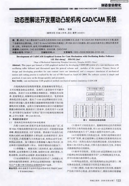
总 体设 计 结 构 图 如 图
( 1 ) 参 数输 入
te
s o
r
im
a r e
la t io
s
f
is
m e c
ha
n
ic
a n
a
l
d
n
a n
tt
in g pr
c a r r
m
o c e s s
is
e m
r e a
liz
n
d by
u
t
he
a n
u s e
o
f V B A t) a
te
s e
d
o n
to
CA D 2 0 0 4
.
The
ftw
y s te
m
,
清晰 模块化程 度 高 可扩充性 强
C 机 构 CA D/ A
、
。
摆 动 滚 子 从 动件 凸 轮
、
。
M
系 统 软 件 主 要 包 括 :运 动 规 律 设 计 基 本
“ 、
、
(4 )凸 轮 轮 廓 和 刀 具 轨 迹 生 成
” ,
。
按 照 凸 轮 图解 法 设 计
尺 寸优 化 凸 轮 轮廓 与 刀 具 轨迹 生 成 机 构 运 动 学 分 析
CADCAM概述

CADCAM概述CADCAM(计算机辅助设计与计算机辅助制造)是指利用计算机技术辅助进行产品设计和制造的工艺方法。
它结合了计算机辅助设计(CAD)和计算机辅助制造(CAM)两个概念,旨在提高设计和制造过程的效率和精度。
本文将概述CADCAM的概念、原理、应用和未来发展趋势。
一、概念CADCAM是现代工程领域中普遍采用的一种技术,它将计算机和软件技术与传统的设计和制造工艺相结合。
CAD技术在设计过程中用于建立和修改产品的几何模型,CAM技术在制造过程中用于将设计模型转化为具体的产品加工工艺。
二、原理CADCAM系统的核心是计算机软件,它能够解析和处理设计数据并自动生成工艺指令。
首先,设计人员使用CAD软件创建产品的几何模型,再将模型导入CAM软件,通过选择适当的加工工艺参数,生成产品的加工路径和指令。
最后,通过将指令传输给加工设备,实现产品的自动加工。
三、应用CADCAM技术在多个领域得到广泛应用。
在制造业中,它可以用于数控机床、激光切割机、3D打印机等机械设备的控制和操作。
在建筑和土木工程领域,CADCAM技术可以用于建筑模型的设计和施工方案的生成。
此外,CADCAM技术在汽车、航空航天、医疗器械等诸多行业都发挥着重要作用。
四、未来发展随着计算机技术的不断发展,CADCAM技术也在不断演进。
未来,CADCAM系统将更加智能化,能够更好地适应复杂产品的设计和制造要求。
与AI技术的结合,可以实现自动化设计和制造的目标,提高生产效率和质量。
总结CADCAM技术是一种利用计算机辅助进行产品设计和制造的工艺方法,它结合了CAD和CAM的概念。
通过计算机软件的应用,CADCAM能够提高设计和制造过程的效率和精度。
该技术在多个领域得到广泛应用,包括制造业、建筑和土木工程等。
未来,CADCAM技术将继续发展,实现更高水平的智能化设计和制造。
什么是CADCAM系统?

什么是CADCAM系统?1、什么是CAD/CAM系统?答:计算机辅助设计(CAD)是指利用计算机辅助设计一个单独的零件或一个系统,设计的过程包含着计算机图形学。
CAD系统是一个设计工具,它支持设计过程的所有阶段——方案设计,初步设计和最后设计。
设计目标的显示是CAD系统最有价值的特征之一,计算机图形学使设计人员能够在计算机屏幕上显示、放大、缩小、旋转设计目标而对其进行研究。
大多数CAD系统使用交互式图形系统,用户能够直接与计算机对话,以便产生、处理和修改图形。
许多CAD系统的最终产品是设计图样,在与计算机连接的绘图仪上产生。
计算机辅助制造(CAM)是指使用计算机辅助制造一个零件。
CAM 有两种类型:①联机应用,使用计算机实时控制制造系统,例如机床的CNC:系统。
②脱机应用,使用计算机进行生产计划的编制和非实时地辅助制造零件,例如用APT语言在穿孔纸带上制备零件程序,或在机械加工中模拟显示刀具轨迹等。
CAD/CAM是一个统一的软件系统,其中CAD系统在计算机内部与CAM系统相连接。
CAD/CAM的最终结果常常是以穿孔带等形式输出零件的加工程序,在当前使用的CAD/CAM系统中,输出的零件程序可以直接送入CNC机床的控制计算机中。
CAD/CAM系统的主要原理是产生一个公用数据库,用于设计和制造全过程。
它们包括制定产品规格、方案设计、最后设计、绘图、制造和检验。
在该过程的每一阶段,数据都可以进行增加、修改、调用,并分布于计算机和终端的网络中。
这就减少了单独数据库提供的人为误差,大大缩短了从产品基本设想的形成到最后实际产品的制造所需的时间。
4、什么是CIMS系统?答:目前CIMS还没有一个完善的、被普遍接受的定义,多数还停留在一般概念上。
1969年美国M.E.Merchant提出(CIMS的概念:CIMS是一个闭环反馈系统,其主要输入是产品需求和产品设计,主要输出是经过组装、检验和准备交付使用的产品。
1976年美国Hatvany教授提出的定义是:CIMS是通过成组技术和数据库管理系统将CAD、CAM和生产计划、管理集在一起的系统。
- 1、下载文档前请自行甄别文档内容的完整性,平台不提供额外的编辑、内容补充、找答案等附加服务。
- 2、"仅部分预览"的文档,不可在线预览部分如存在完整性等问题,可反馈申请退款(可完整预览的文档不适用该条件!)。
- 3、如文档侵犯您的权益,请联系客服反馈,我们会尽快为您处理(人工客服工作时间:9:00-18:30)。
Int J Adv Manuf Technol(1999)15:32–37©1999Springer-Verlag LondonLimitedA CAD/CAM System for High Performance Precision Drum CamsS.H.MasoodIndustrial Research Institute Swinburne,Swinburne University of Technology,Melbourne,AustraliaThis paper describes a computer-aided design and manufactur-ing system for the design and production of complex profiles for high-performance drum cams within the specified tolerance. The system graphically generates the cam profile on the cylin-drical drum after performing an analysis of the kinematic performance for the prescribed follower motion,using a B-spline representation of follower curves.Eight different types of follower motion for a translating follower are considered. The kinematic performance is based on the criteria of achieving the lowest levels of velocity and acceleration for each curve. The system is also able to simulate the motion of the designed cam graphically.The system also recommends the best cam profile on the basis of comparing the kinematic performance of all the B-spline representations of all the follower motions. Keywords:B-spline;Cam profiles;CNC machining;Cylindri-cal cams;Drum cams1.IntroductionA drum cam is a cylindrical cam which transmits motion to its follower in a groove cut on the surface of a cylinder.The cam rotates about its longitudinal axis and provides a trans-lational and/or oscillational displacement to the follower,simul-taneously.Applications of such cams are found in,for example, knitting machines,elevators,packing machines and indexing mechanisms.Requirements for high performance of such machinery demands efficient methods for the design and manu-facture of such cams.Conventional methods of design and machining complex drum cam profiles within a given accuracy are tedious and time consuming.Even programming them on a computer numerical control(CNC)machine can be a difficult job because of the complexity of the cam profiles.This paper describes a CAD/CAM system for the design and production of complex profiles for high performance drum cams within a specified tolerance.The system graphically generates the cam profile on the cylindrical drum,after per-Correspondence and offprint requests to:Dr S.H.Masood,IRIS, Swinburne University of Technology,Hawthorne,Melborne3122, Australia.forming an analysis of the kinematic performance of the pre-scribed follower motion,using a B-spline representation of follower curves.A number of different types of follower motions for a translating follower are considered.The kinematic performance is based on the criteria of achieving the lowest levels of velocity and acceleration for each curve.The system is also able to simulate graphically the motion of the designed drum cam.The system recommends the best cam profile on the basis of comparing the kinematic performance of all the B-spline representations of all the follower motions.The system also generates the tool cutter location data for the CNC machining of the drum cam profile.With the user specified tolerance,the system provides the minimum number of cutter location points required for machining the profile within the given accuracy.It is demonstrated that the adopted approach used in this CAD/CAM system provides a faster and more economical method of designing and manufacturing precision drum cams.2.Related WorkSeveral studies have been carried out on the design,production, and performance of cams,especially for disk or plate cams [1–3].Initially,the researchers concentrated on the method-ology for describing the surface of the profile.With the advent of powerful computers,work has been concentrated on the development of computer programs to assist in the design and manufacture of cams.Some of this work includes curvefitting for smoothing the motion curves of the cam when rotating at high speed.Most work is related to plate cams,but little work seems to have been done on cylindrical cams.Lin et al.[4]have developed a methodology by which cam drawings and NC codes can be automatically created after specifying the cam motion function.The procedure they have developed for cam design is based on a methodology called combined curvesfitting.The methodology is to establish the necessary equation for matching the velocities and accelerations at the curve junctions.From this equation,the cam profile coordinates can be ing the cam profile coordinates and the size and type of cam follower,the cutter centre coordinates can be calculated for a specified increment of cam rotation.Their work concentrated more on how to obtain anA CAD/CAM System for Precision Drum Cams33accurate profile,rather than on how to generate an accurate NC code.Yang and Kim[5]developed an interactive CAD/CAM system for the integrated design and manufacture of precision plate cams with three interpolation methods.The method using the cutting tool to assume the role of the follower was called R-⌰interpolation and generates the least number of NC curves compared to linear interpolation methods.Sadek and Daadbin[6]proposed a method of smoothing the profile curve once it had been specified.Polynomial curve fitting was used to replace the profile curve.A two-degree-of-freedom model for a cam mechanism is used as a test case. The conclusion is that with curvefitting using polynomials, the cam can cause less vibration than does the original cam and it has less tendency to bounce.However,their work does not deal with the development of diagrams,simulation and the manufacture of cams.Masood and Lau[7]developed a CAD/CAM system for the accurate machining of plate cams within a user specified tolerance.Their work includes the generation of a displacement diagram,the simulation of cam tool-path generation and the generation of actual CNC codes.They also proposed a new method for the interpolation of cam profiles called the half-angle algorithm,which produces more economical CNC part programs than other interpolation methods.Chan and Sim[8]developed a computer-aided design tool for optimum plate cam design.An exploratory search method called the Monte Carlo method was used to optimise the cam design.In this method,random points are generated over the range of all variables of the cam base circle,the width of the cam,the follower roller radius and its offset.The system is an integration of the design calculations and an optimisation algorithm.It provides an optimised solution,a graphical dia-gram,and a simulation of cam movement but does not provide the data for cam machining.Dhande et al.[9]developed a method of generating the profiles of planar and spatial cams.The method used is based on the concept that the common normal vector and the relative velocity vector are orthogonal to each other at the point of contact between the cam and follower.By this method,the contact line on the follower surface can be formed and then transformed in the coordinate system of the cam,giving the conjugate cam profile.This research focused only on how to obtain the coordinates of3D cams such as cylindrical or conical cams.None of this research concentrates on the full development of a CAD/CAM system for cylindrical cams. More recently,Tsay and Wei[10]developed a CAD system for cylindrical cams with a translating conical follower.Cams can be designed and graphics can be displayed once the follower motion program has been given.Based on the approach previously developed by in[9],the contact line of the follower at any angle of rotation can be obtained tofind analytical profile expressions.All these procedures were carried out without the assistance of a CAD/CAM system.Tsay and Lin[11]presented a procedure for the synthesis and analysis of the surface geometry of cylindrical cams with oscillating roller followers.B-splines are used to synthesise and refine the dwell-rise-dwell motion.To justify the method, the maximum acceleration and velocity of B-spline cams were compared with those using traditional curves of cycloidal and modified sine types.Work was under way for calculating the tool path for the machining of the cylindrical cam on a numerical control milling machine.3.Basic Follower Motion CurvesGenerally,thefirst task in the design of a cylindrical cam is to select a suitable follower motion curve that will satisfy the constraints of the application.Here,the constraints mean the relationship of the displacement of the follower to the angle of rotation.The follower motion curves play an important role in the performance of the cam mechanism.The desirable characteristics of the motion curves are that they should impart a continuous velocity,continuous acceleration,and low velocity and low acceleration to the follower.These may not be important when a cam is operating at low speed,but will be crucial at high speeds since they can result in high vibrations and may lead to a short life span for cam and other mechanisms in the machine.Cams with complex profiles are often required.This may involve a number of rise-dwell-return intervals in which the rise and return motions may be quite different to each other. To analyse the action of a cam,it is therefore necessary to study its displacement–time diagram and its associated velocity and acceleration curves.Some of the most common types of follower motion curve selected by cam designers are:1.Constant velocity.2.Parabolic motion.3.Simple harmonic motion.4.Cycloidal motion.5.The3–4–5polynomial motion.6.Modified sine motion.7.Trapezoidal motion.8.The4–5–6–7polynomial motion.In constant velocity motion,the velocity of the follower during the motion is constant,and the acceleration is zero,except at the beginning and the end of the motion,where the acceleration reaches infinity instantaneously.In parabolic motion,this curve has constant acceleration and retardation following a parabolic equation.Simple harmonic motion has a smooth,continuous acceleration but has a sudden change in acceleration at the ends.It is,therefore,suitable only for cams at medium or low speed.Cycloidal motion is obtained by rolling a circle on a straight line.The length of the line is equal to the circumference of the rolling circle.It has the smoothest motion among all of the basic curves,and therefore,it is suitable for high-speed applications.The3–4–5polynomial curve is worked out from a5th degree polynomial.It can generate a smooth and accept-able profile that will fulfil the design requirements.Its perform-ance at high speed is good.It is suitable for cams at medium speeds.The modified sine curve is a combination of cycloidal and harmonic quadrants occupying different parts of the work-34S.H.Masooding cycle.This curve has a low maximum velocity and good acceleration characteristics.Its performance at high speed is good or excellent.The trapezoidal motion curve,if machined accurately,will be good for high-speed cams.It has good acceleration characteristics.The4–5–6–7polynomial has been developed from a3–4–5polynomial.The smoothness of the curve is similar to that of a3–4–5polynomial.It has good acceleration characteristics and is used for high-speed cams.4.Synthesis of Follower Motion Curves Using B-SplinesWhen the kinematic and dynamic performances of the cam-follower mechanisms are to be considered,the follower motion must be carefully synthesised.For example,to reduce the amplitude of the inertial force,the maximum value of the acceleration curve of the follower motion must be as small as possible.One method of improving the follower motion curves would be to represent the curves by parametric B splines. 4.1B-spline CurvesThe term“spline”refers to a smooth curve drawn through a set of plotted control points.Such curves can be described mathematically as piecewise approximations of cubic poly-nomial functions having all three orders of continuity(zero-order,first-order,and second-order continuity).The smoothness of a curve is described in terms of curve continuity between sections.Zero-order continuity means that the curves intersect. First-order continuity means that the tangent lines(first derivatives)of two adjoining curve sections are the same at the intersection.Second-order continuity means that the curvatures (second derivatives)of the two curve sections are the same at the intersections.B-splines are a class of spline curves that cannot only interpolate a given set of control points,but can also allow localised modifications to be made easily without greatly affect-ing other parts of the curve[12].Another advantage of B-splines is that any number of control points can be specified by a designer without increasing the degree of the curve.A cubic curve could then be used for many different curve shapes,without the need to piece curve segments together. Any number of control points can be added or modified to manipulate the curve shape.Given an input set of n+1control points p i,with i varying from0to n,then the points on the approximating B-spline curve are given by,p(u)=⌺p i N i,k(u)where N i,k(u)is defined as a blending function,which is a polynomial of degree kϪ1.A method for setting up the polynomial form of the blending functions is to define them recursively over various subintervals of the range for para-meters u.This range now depends on the number of control points n and the choice for k,so that u varies from0to nϪk+2(instead of0to1).Setting up n+k subintervals,we define the blending functions recursively asN i,1(u)=1if t iϽuϽt i+1N i,1(u)=0otherwiseandN i,k(u)=[(uϪt i)N i,kϪ1(u)]/[t i+kϪ1Ϫt i]+[(t i+kϪu)N i+1,kϪ1(u)]/[t i+kϪt i+1]where k controls the degree(kϪ1)of the resulting polynomial in u and thus also controls the continuity of the curve.The values t i are called knot values.They relate the parametric variable u to p i control points.The knot values t i are given by t i=0if iϽkt i=iϪk+1if kՅiՅnt i=nϪk+2if iϾnwith0ՅiՅn+k4.2Applying a B-spline Approximation to a Basic CurveIn cam design,once the basic follower motion curve has been specified,it can then be approximated by B-splines.The following steps illustrate the procedure by a simple example.1.Create the basic curve of the selected follower motion(parabolic,simple harmonic,etc).2.Divide the angle interval of the curve into5parts.Eachpart has the same angle interval.This will create6points, p0,p1,p2,p3,p4,and p5lying on the curve.3.These6control points are interpolated by considering theconstraints of n=5,and k=3and using the parametric equations:p x,y=(1Ϫu)3p0+[u(1Ϫu)2+1/2(2Ϫu)(Ϫ3/2u2+2u)]p1+[u/2(Ϫ3/2u2+2u)+u2/6(3Ϫu)]p2+u3/6p3if0ՅuϽ1 p x,y=1/4(2Ϫu)3p1+[u/4(2Ϫu)2+(3Ϫu)/3(Ϫu2+3uϪ3/2)]p2+[u/3(Ϫu2+3uϪ3/2)+1/4(3Ϫu)(uϪ1)2]p3+1/4(uϪ1)3p4if1ՅuϽ2 p x,y=1/6(3Ϫu)3p2+[u/6(3Ϫu)2+(3Ϫu)/2(Ϫ3/2u2+7uϪ15/2)]p3[(uϪ1)/2(Ϫ3/2u2+7uϪ15/2)+(3Ϫu)(uϪ2)2]p4+(uϪ2)3p5if2ՅuϽ3 where p x is the x-coordinate point and p y is the y-coordinate point on the curve.Using the above procedure,each motion curve is converted into an equivalent B-spline curve.The new curve many look approximately the same as the former basic curve but it will have differences in the smoothness and maximum velocity and acceleration.These are the factors that affect the kinematicA CAD/CAM System for Precision Drum Cams35performance of the cam.The velocity and acceleration diagram of various cams can be examined using the CAD/CAM system which has been developed.For machining the cam on a CNC machine,the cutter location data required to machine the specified cam profile should be minimised.This will result in a shorter programming time and more economical CNC programs.The system calcu-lates the cutter location data required for the cam profile on the basis of the basic curve as well as the interpolated B-spline curve.5.The CAD/CAM SystemThe CAD/CAM system for a drum cam presented in this paper is an interactive computer program written in Pascal version 7.A computer with an80386or higher CPU with a DOS operating system is required.The system requires the user to specify the following input data from the main menu:1.Speed of cam rotation(r.p.m.).2.Tolerance to be achieved(mm).3.Type of basic curves for each segment of motion curve(selected from the list).4.Direction of the follower(lift/return).5.Interval angle for each segment of the motion curve(degrees).Then,the program computes the cam profile to provide the specified follower motion and generates the following infor-mation:1.Graphical display of displacement,velocity and accelerationdiagrams for the basic curve and the B-spline curve.2.Numerical values of maximum acceleration and maximumvelocity for the basic curve and the B-spline curve.3.Cutter location data points for CNC machining using thebasic curve,using the B-spline curve,and using the edited curve.4.2D animated graphical simulation of drum cam with itsprofile.5.3D animated graphical simulation of drum cam with itsprofile.Using the information from items1or2above,the user can decide whether the basic curve or the B-spline curve is to be used for profile generation.In general,it is expected that the B-spline curve will provide lower velocity and acceleration for a given set of combination of motion curves for the rise and return motions of the follower of a particular cam.The system also allows the user to generate CNC cutter location data for the cam profile on the basis of basic curves alone,or the B-spline curves alone,or the edited curves.The cam profile generated on the basis of the edited curve will generate the minimum number of CNC cutter location points. This is done by comparing the cutter location data for each segment of the basic curve with the cutter location data for the corresponding segment of the B-spline curve,and then selecting the segment with the lower number of cutter location data.In this way,an edited curve is the motion curve that contains a combination of portions of the basic curve as well as a B-spline curve.The system employs the half angle search algorithm.This provides a systematic searching method to determine the mini-mum number of NC points required for machining the cam profile to within a user specified tolerance[7].The limitation of the program is that for each of the curves defined,the value of the ratio of the angle interval to the height for rise,dwell or return,has to be more than10.For example,if we want to input the cam profile with a rise from 0°to120°with a cycloidal motion,a dwell from120°to 240°,and a return from240°to360°with a modified sine motion,then the height of the follower motion curve should be less than10to make the ratio of angle/height more than 10.This limitation is because the motion curve must have a certain horizontal spread in order to convert it to a B-spline, and also because of the requirements of the half angle search algorithm used for linear interpolation of the profile curve. 6.Analysis of Motion CurvesUsing the CAD/CAM system,an analysis was performed to demonstrate that B-spline curves of all the types of motion curves produce a lower number of cutter location data points. For this,a drum cam with a follower motion consisting of only rise and return(with no dwell),each with an angle interval of180°and a maximum height of100mm,was considered.The drum cam profile was created by considering each type of follower motion(parabolic,SHM,etc.)in turn. In each case,the motion curves for the rise and return motion were assumed to be identical.For example,in the case of parabolic motion,the rise and return motions were each assumed to be parabolic with an angle interval of180°each. The cam speed was assumed to be60r.p.m.The cam profiles were generated in each case for each of three different values of tolerance.Table1shows that the approximated B-spline curves for each type of follower motion produce fewer CNC cutter location points than those generated for the basic curve for the corresponding type of follower motion.An analysis was also performed to determine the maximum velocities achieved by a drum cam designed for different types of follower ing a follower displacement height of 100mm,with a tolerance of0.005,the CAD/CAM system was used to compute the maximum velocities for each drum cam in which the rise and return had equal angle intervals of 180°and with the rise and return having the same type of motion curve.This was done for all seven types of motion (parabolic,SHM,etc.).Three cam speeds were used.The results in Table2show that the approximated B-spline curve of each follower motion provides lower maximum velocities than the basic curve for the corresponding follower motion at different speeds of cam rotation.A similar analysis has been carried out for maximum acceleration,but the values of maximum acceleration are found to be lower for the basic motion curves than for the approximated B-spline curves in most cases.36S.H.MasoodTable1.Number of cutter location points required for basic curve and approximated B-spline curves for different follower motions.Type of Specified tolerance(mm)followermotion curve0.0010.0020.0051.Parabolic:Basic885835B-spline6940242.Simple harmonic:Basic714628B-spline7442263.Cycloidal:Basic745634B-spline6638224.The3–4–5polynomial:Basic745032B-spline7040245.Modified sine:Basic744831B-spline7040246.Trapezoidal:Basic805432B-spline6840227.The4–5–6–7polynomial:Basic986032B-spline643821Table2.Maximum velocity for basic and B-spline motion curves.Type of Cam speed(r.p.m.)followermotion curve1020601.Parabolic:Basic 6.6713.3340B-spline 5.7811.5634.672.Simple harmonic:Basic 5.2410.4731.42B-spline 5.5211.0433.133.Cycloidal:Basic 6.6713.3340B-spline 6.0012.1036.024.The3–4–5polynomial:Basic 6.2512.5037.5B-spline 5.8211.6434.925.Modified sine:Basic 5.8711.7335.19B-spline 5.6511.2933.886.Trapezoidal:Basic 6.6713.3340B-spline 5.9512.8335.727.The4–5–6–7polynomial:Basic7.2914.5843.75B-spline 6.2812.5637.69From the above analysis,it is clear that,from among thebasic curves,the curve that gives the least number of cutterlocation(CL)points is a simple harmonic motion,while thecurve with the most CL data is a4–5–6–7polynomial.How-ever,when comparing the B-splines of all the curves,the curvewith the least CL data is the4–5–6–7polynomial.Thus a B-spline curve of the4–5–6–7polynomial type is the preferablecurve when the quantity of CL data is the main consideration,and the cam does not operate at high speeds.Considering the maximum velocities,among the basiccurves,the one that gives the lowest velocity is the simpleharmonic motion,while the one with the highest maximumvelocity is the4–5–6–7curve.Therefore,the simple harmonicis preferable when the designer wants a cam running at a lowspeed.Considering the maximum accelerations,the parabolicmotion basic curve provides the lowest maximum acceleration Fig.1.Example of a drum cam designed by the CAD/CAM system.A CAD/CAM System for Precision Drum Cams37among the other basic curves,but other curves such as simple harmonic and trapezoidal motion also provide lower acceler-ations.When considering each curve and its B-spline form in turn,the results indicate that the cycloidal and the4–5–6–7 polynomial curves,with their B-spline forms will give better performance when low acceleration is required.Figure1shows an example of a drum cam design and a simulation created by the CAD/CAM system.7.ConclusionsThe CAD/CAM system for the design and machining of drum cams discussed in this paper is based upon the kinematic performance of the cam and includes a provision for improving the performance of the cam by considering an approximated B-spline representation of each motion curve.The system provides useful design information such as maximum velocities and maximum accelerations for each of the selected follower motion diagrams and for their approximated B-spline represen-tations,and the number of cutter location points required for the CNC machining of the cam profile.The system also allows the design of cams within user specified tolerance levels.The analysis of various follower motion curves for cutter location data,low maximum velocity and low maximum acceleration has been carried out to help the designer select the desirable type of motion curves for better cam performance.References1.F.Y.Chen,Mechanics and Design of Cam Mechanisms,JohnWiley,1982.2.P.W.Jensen,Cam Design and Manufacture,2nd edn,MarcelDekker,1987.3.D.Tesar and G.K.Matthew,The Dynamic Synthesis,Analysisand Design of Modelled Cam Systems,Lexington Books,1976.4.A.C.Lin,H.Chang and H.P.Wang,“Computerised design andmanufacturing of plate cams”,International Journal of Production Research,26(8),pp.1395–1430,1988.5.M.Yang and C.Kim,“A CAD/CAM system for precision camswith three CNC interpolation methods”,International Journal of Advanced Manufacturing Technology,9,pp.87–92,1994.6.K.Sadek and A.Daadbin,“Improved cam profiles for high-speedmachinery using polynomial curvefitting”,Journal of Process Mechanical Engineering,204,pp.127–132,1990.7.S.H.Masood and u“A CAD/CAM system for the machiningof precision cams using a half angle search algorithm”,Inter-national Journal of Advanced Manufacturing Technology,14(3), pp.180–184,1998.8.W.Chan and S.Sim,“Optimum cam design”,International Journalof Computer Applications in Technology,9(1),pp.34–47,1996.9.S.G.Dhande, B.S.Bhadoria and J.Chakraborty,“A unifiedapproach to the analytical design of three-dimensional cam mech-anisms”,ASME Journal of Engineering for Industry,97B(1),pp.327–333,1975.10.Der Min Tsay and Hsien Min Wei,“Design and machining ofcylindrical cams with translating conical followers”,Computer-Aided Design,25(10),pp.655–661,1993.11.Der Min Tsay and Ber Jeng Lin,“Improving the geometry designof cylindrical cams using nonparametric rational B-spline”,Com-puter-Aided Design,28(1),pp.5–15,1996.12.M.E.Mortenson,Geometric Modelling,John Wiley,1985.。