ELS-432SRWA中文资料
LM432中文资料
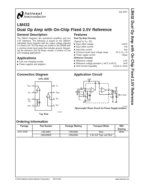
LM432Dual Op Amp with On-Chip Fixed 2.5V ReferenceGeneral DescriptionThe LM432integrates two operational amplifiers and one 2.5V reference.The reference is based on the LMV431adjustable shunt regulator with the output voltage adjusted to a fixed 2.5V.The Op Amps are similar to the LM358with a common-mode input range that includes ground.Integrat-ing the reference and Op Amps creates a solution for low cost charging applications.Applicationsn Low cost charging circuitry n Power supplies and adaptersFeaturesDual Op Amp Circuitry (Typical for V S =5V)n Input offset voltage 0.6mV n Input offset current 1nA n Input bias current3nAn Common-mode input voltage range 0V to V S −1Vn Power supply current150µAReference Circuitry n Reference voltage 2.5V n Reference voltage deviation (−40˚C to 85˚C)4mV n Sink Current Capability 0.2mA to 10mAConnection Diagram8-Pin SOIC10139001Top ViewApplication Circuit10139002Optocoupler Driver Circuit for Power Supply IsolationOrdering InformationPackage Part Number Package MarkingTransport MediaNSCDrawing 8-Pin SOICLM432MA LM432MA RailsM08ALM432MAXLM432MA2.5k Unit Tape and ReelJuly 2001LM432Dual Op Amp with On-Chip Fixed 2.5V Reference©2004National Semiconductor Corporation Absolute Maximum Ratings (Notes 1,3)If Military/Aerospace specified devices are required,please contact the National Semiconductor Sales Office/Distributors for availability and specifications.Suppy Voltage (V S )20VStorage Temperature −65˚C to 150˚CJunction Temperature (T J )150˚C ESD Human Body Model2kVInput Voltage Range −0.3V to 20VOperating Ratings (Note 2),(Note 3)Temperature Range −40˚C to 85˚C Supply Voltage (Note 8) 2.5V to 16V Thermal Resistance(θJA )162˚C/WElectrical CharacteristicsThe following specifications apply for both amplifiers at V S =5V,V CM =2.5V,V O =2.5V,R L =∞,and T J =25˚C,unless other-wise noted.SymbolParameterConditionsMin (Note 5)Typ (Note 4)Max (Note 5)UnitsOP Amp Circuitry V OS Input Offset Voltage Amplifier B only −40.64mV I OS Input Offset Current Amplifier B only 150nA I B Input Bias CurrentAmplifier B only 3150nA V CM Common-Mode Input Voltage Range Amplifier B only,CMRR >50dB 0V S -1V I S Power Supply Current Total for both amplifiers 150500µA A V Voltage Gain V S =16V,1V <V O <11V,R L =10k Ωconnected to V S /265100dB V OL Output Voltage Low 250mV V OH Output Voltage High V S –1.5V S –1.3V I SOURCE Output Current Source 2030mA I SINK Output Current Sink511mA Reference Circuitry For Op Amp A The following specifications apply for I Z =200µA and T J =25˚C,unless otherwise noted.V Z Reference Voltage at IN +Terminal 2.4502.5 2.550V V ZDEVReference Voltage Deviation at IN +Terminal Over Temperature (Note 6),(Note 9)−40˚C ≤T J ≤85˚C465mVI Z (MIN)Minimum Cathode Current for Regulation at IN +(V Z )Terminal 150200µA r zDynamic Output Impedance (Note 7)200µA <I Z <1mA,Freq =0Hz0.2ΩNote 1:Absolute Maximum Ratings indicate limits beyond which damage to the device may occur.Note 2:Operating Rating indicate conditions for which the device is functional.These rating do not guarantee specific performance limits.For guaranteed specifications and test conditions,see the Electrical Characteristics.The guaranteed specifications apply only for the test conditions listed.Some performance characteristics may degrade when the device is not operated under the listed test conditions.Note 3:All voltages are measured with respect to GND =0V DC ,unless otherwise specified.Note 4:Typicals represent the most likely parametic norm.Note 5:Guaranteed to National’s Average Outgoing Quality Level (AOQL).Note 6:Reference voltage deviation,V ZDEV ,is defined as the maximum variation of the reference input voltage over the full temperature range.Note 7:The Dynamic Output Impendance,r z ,is defined as r z =∆V Z /∆I Z .Note 8:Minimum value of operating voltage is for Amplifier B only.Note 9:Typical Temperature drift ∆V/∆T =12.8ppm/˚CL M 432 2Physical Dimensionsinches (millimeters)unless otherwise noted8-Pin SOICNS Package Number M08ALIFE SUPPORT POLICYNATIONAL’S PRODUCTS ARE NOT AUTHORIZED FOR USE AS CRITICAL COMPONENTS IN LIFE SUPPORT DEVICES OR SYSTEMS WITHOUT THE EXPRESS WRITTEN APPROVAL OF THE PRESIDENT AND GENERAL COUNSEL OF NATIONAL SEMICONDUCTOR CORPORATION.As used herein:1.Life support devices or systems are devices or systems which,(a)are intended for surgical implant into the body,or (b)support or sustain life,and whose failure to perform when properly used in accordance with instructions for use provided in the labeling,can be reasonably expected to result in a significant injury to the user. 2.A critical component is any component of a life support device or system whose failure to perform can be reasonably expected to cause the failure of the life support device or system,or to affect its safety or effectiveness.BANNED SUBSTANCE COMPLIANCENational Semiconductor certifies that the products and packing materials meet the provisions of the Customer Products Stewardship Specification (CSP-9-111C2)and the Banned Substances and Materials of Interest Specification (CSP-9-111S2)and contain no ‘‘Banned Substances’’as defined in CSP-9-111S2.National Semiconductor Americas Customer Support CenterEmail:new.feedback@ Tel:1-800-272-9959National SemiconductorEurope Customer Support CenterFax:+49(0)180-5308586Email:europe.support@Deutsch Tel:+49(0)6995086208English Tel:+44(0)8702402171Français Tel:+33(0)141918790National Semiconductor Asia Pacific Customer Support CenterEmail:ap.support@National SemiconductorJapan Customer Support Center Fax:81-3-5639-7507Email:jpn.feedback@ Tel:81-3-5639-7560LM432Dual Op Amp with On-Chip Fixed 2.5V ReferenceNational does not assume any responsibility for use of any circuitry described,no circuit patent licenses are implied and National reserves the right at any time without notice to change said circuitry and specifications.。
TL432-CSF中文资料

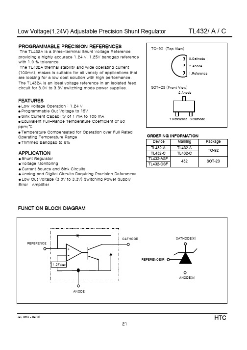
TL432/ A / C
ABSOLUTE MAXg Ambient Temperature Range Applies Unless Otherwise Noted)
CHARACTERISTIC Cathode Voltage Continuous Cathode Current Range Reference Input Current Range Junction Temperature Operating Temperature Storage Temperature Total Power Dissipation
APPLICATION
● Shunt Regulator ● Voltage Monitoring ● Current Source and Sink Circuits ● Anolog and Digital Circuits Requiring Precision References ● Low Out Voltage (3.0V to 3.3V) Switching Power Supply Error Amplifier
|ZKA|=
ΔVKA ΔIKA
The dynamic impedance is defined as :
When the device is operating with two external resistors (see Figure 3), the total dynamic impedance of the circuit is given by :
SYMBOL VKA IKA IREF TJ TOPR TSTG PD
RATING 15 100
-0.05 ~ 3 -40 ~ 150
0 ~70 -65~+150
麦克维尔产品手册

750
800
800
850
850
900
950
1000
1100
1200
1300
输入功率
kW
447.3
462
489.1
504.5
518.5
526.4
558.4
587.5
619.9
680.1
759
824.7
电源
380V/3N〜/50Hz
注:■ 以上选型适用于冷冻水进/出水温度为 12℃/7℃,冷却水进/出水温度为 32℃/37℃,换热器流程数为 2 流程。
40 热泵热水机组
模块式空气源热泵热水机组MHA
42 末端空调机组
组合式空气处理机组 MDM 洁净室用空气调节机组 MDX 单壁柜式空气处理机组 MSW 双壁柜式空气处理机组 MDW 超薄吊顶式空气处理机组 MHW 卧式暗装风机盘管 MCW 立式暗装风机盘管 MFCW 立式明装风机盘管 MFMW 天花嵌入式风机盘管 MCKW 卧式明装风机盘管 MCMW 吊顶式全热热回收新风机组 HRB
79 轻型商用空调机组
天花嵌入式分体空调器 MCK-T 明装吊顶/座地式分体空调器 MCM-D 暗装吊顶式分体空调机组 MCC-T 风冷冷风/热泵型管道式空调机 MDB“T”系列 风冷冷风/热泵型管道式空调机 MDB“M”系列 风冷冷风/热泵型管道式空调机 MDB“S”系列 “旋风”系列水冷柜机 MWCP 屋顶式空调机组 MRT
AX432资料
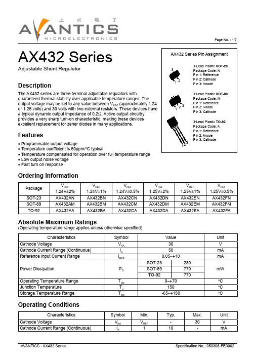
Page No. : 1/7AX432 SeriesAdjustable Shunt RegulatorDescriptionThe AX432 series are three-terminal adjustable regulators withguaranteed thermal stability over applicable temperature ranges. The output voltage may be set to any value between V REF (approximately 1.24or 1.25 volts) and 30 volts with two external resistors. These devices have a typical dynamic output impedance of 0.2Ω. Active output circuitry provides a very sharp turn-on characteristic, making these devices excellent replacement for zener diodes in many applications.Features• Programmable output voltage• Temperature coefficient is 50ppm/o C typical• Temperature compensated for operation over full temperature range • Low output noise voltage • Fast turn on responseOrdering InformationPackage V REF1.24V ±2%V REF1.24V ±1%V REF1.24V ±0.5%V REF1.25V ±2%V REF1.25V ±1%V REF1.25V ±0.5%SOT-23AX432AN AX432BN AX432CN AX432DN AX432EN AX432FN SOT-89AX432AM AX432BM AX432CM AX432DM AX432EM AX432FM TO-92AX432AAAX432BAAX432CAAX432DAAX432EAAX432FAAbsolute Maximum Ratings(Operating temperature range applies unless otherwise specified)CharacteristicsSymbol ValueUnit Cathode VoltageV KA 30V Cathode Current Range (Continuous)I K 50mA Reference Input Current Range I REF 0.05~+10mA SOT-23280SOT-89770Power DissipationP D TO-92770mWOperating Temperature Range T opr 0~+70oC Junction TemperatureT J 150o C Storage Temperature RangeT stg-65~+150o COperating ConditionsCharacteristicsSymbol Min.Typ.Max.Unit Cathode VoltageV KA V REF -30V Cathode Current Range (Continuous)I K110-mAPage No. : 3/7Characteristics CurvePage No. : 5/7 SOT-89 DimensionTO-92 DimensionPage No. : 6/7 SOT-23 DimensionImportant Notice:• All rights are reserved. Reproduction in whole or in part is prohibited without the prior written approval of AVANTIC.• AVANTICS reserves the right to make changes to its products without notice.•AVANTICS semiconductor products are not warranted to be suitable for use in Life-Support Applications, or systems.• AVANTICS assumes no liability for any consequence of customer product design, infringement of patents, or application assistance.Head Office:• AVANTICS Microelectronics Corp: No. 255, Cai Lun Rd. Zhangjiang Technology Industrial Park Pudong, Shanghai, ChinaTel: 86-021-******** Fax: 86-021-********Page No. : 7/7Soldering Methods for AVANTICS’s Products1. Storage environment: T emperature=10o C~35o C Humidity=65%±15%2. Reflow soldering of surface-mount devicesProfile FeatureSn-Pb Eutectic AssemblyPb-Free AssemblyAverage ramp-up rate (T L to T P )<3o C/sec<3o C/secPreheat- T emperature Min (T s min )- T emperature Max (T s max )- Time (min to max) (ts)100o C 150o C 60~120 sec150o C 200o C 60~180 secT smax to T L - Ramp-up Rate <3o C/sec <3o C/secTime maintained above:- T emperature (T L )- Time (t L )183o C 60~150 sec 217o C 60~150 sec Peak T emperature (T P )240o C +0/-5o C 260o C +0/-5o C Time within 5o C of actual Peak T emperature (t P )10~30 sec 20~40 sec Ramp-down Rate<6o C/sec <6o C/sec Time 25o C to Peak T emperature <6 minutes<8 minutes3. Flow (wave) soldering (solder dipping)ProductsPeak temperature Dipping time Pb devices.245o C ±5o C 5sec ±1sec Pb-Free devices.260o C +0/-5o C5sec ±1sec。
射频测试仪器技术培训课件

✓规范操作流程
首先关断信号源输出;测试时必须先给 被测件加电,然后再连接测试仪表;测 试完毕,要拆卸连接时应先关断信号源 输出,卸下电缆,关断电源
PPT学习交流
21
基本使用操作 -E4432B
频率幅度选择按键
功能按键框
屏幕菜单操作按键
调制开关
电源开关 频率和幅度调节轮
RF输出
频率和幅度增减 数字按键
(Bluetooth, 1xEV-DO)
✓E443xB 专用固件 (3GPP W-CDMA, cdma2000, IS-95-A, GSM/EDGE)
✓可以通过GPIB 和 RS-232 监控
PPT学习交流
8
射频测试仪器介绍
按功能分为以下几大类: 1、信号源系列 2、频谱仪系列 3、网络分析仪系列
✓正确校准仪器
正确校准仪器是保证测试准确度的关键,用信 号源和频谱仪校准电缆损耗时,推荐信号源输出 电平为0dBm,用网络分析仪测试无源器件时推荐 网络分析仪输出功率为0dBm。但要注意射频仪器 上电后需预热至少5分钟后再行校准。
PPT学习交流
20
仪器使用注意事项
✓正确连接测试仪器
被测件与仪器连接时,要求先连接被测件输出 端,尤其对于大功率设备;对于测试双向信号 传输的设备,当其输出功率较大时,要求在信 号源输出端连接隔离器,在频谱仪或网络分析 仪输入端连接衰减器。
PPT学习交流
18
仪器使用注意事项
✓测试仪器选择 根据测试任务选择合适的测试仪表很重要,为确保测 试精度,应从测试仪表的输出、输入、动态特性结合被 测试件的指标确定测试仪器和附件,如衰减器、隔离器 等等。
✓仪表供电电源确认
大多数测试仪器供电具有AC110V和AC220V,上电前 务必检查并确认电源选择开关拨至AC220一边。
TL432-C中文资料

VKA=1.25V to 14.5V
IREF
R1=10Leabharlann , R2=∞ΔIREF/ΔT R1=10㏀, R2=∞, Ta = Full Range
IKAMIN IKAOFF
Vka=Vref VKA=15V, VREF=0
1.0 2.7 ㎷/V
0.5
1
㎂
0.05 0.3
㎂
60
80
㎂
0.04 0.5
㎂
Dynamic Impedance
TA=70℃
TA=85℃
TA=125℃
Power Rating Power Rating Power Rating
491㎽
398㎽
-
-
-
-
149㎽
122㎽
-
Jan, 2004 - Rev 01
22
HTC
元器件交易网
Low Voltage(1.24V) Adjustable Precision Shunt Regulator
|αVREF|= ( 1274.21㎷㎷)x106 ~~ 46PPM/℃ 125℃
Because minimum VREF occurs at the lower temperature, the coefficient is positive.
Calculating Dynamic Impedance
FEATURES
● Low Voltage Operation : 1.24 V ● Programmable Out Voltage to 15V ● Sink Current Capability of 1 mA to 100 mA ● Equivalent Full-Range Temperature Coefficient of 50 ppm/℃ ● Temperature Compensated for Operation over Full Rated Operating Temperature Range ● Trimmed Bandgap to 5% ● ESD Protection : 2kV
TL432-ASF中文资料
αVREF can be positive or negative, depending on whether minimum V REF or maximum VREF, respectively, occurs at the lower temperature.
Example : Maximum VREF=1190㎷ at 30℃, maximum VREF=1262㎷ at 0℃, VREF=1241㎷ at 25℃, ΔTA=125℃ for TL431C
TL432/ A / C
ABSOLUTE MAXIMUM RATINGS
(Full Operating Ambient Temperature Range Applies Unless Otherwise Noted)
CHARACTERISTIC Cathode Voltage Continuous Cathode Current Range Reference Input Current Range Junction Temperature Operating Temperature Storage Temperature Total Power Dissipation
|Z'|=
ΔV ΔI
~~|ZKA| (1+
R1 R2 )
Jan, 2004 - Rev 01
25
HTC
VKA=1.25V to 14.5V
IREF
R1=10㏀, R2=∞
ΔIREF/ΔT R1=10㏀, R2=∞, Ta = Full Range
IKAMIN IKAOFF
Vka=Vref VKA=15V, VREF=0
1.0 2.7 ㎷/V
西尔西斯 R2 R4 数据采集系统用户指南说明书
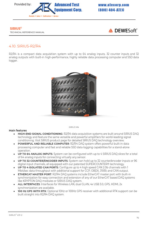
SIRIUS®TECHNICAL R EFERENCE M ANUAL4.10. S IRIUS-R2/R4R2/R4 i s a c ompact d ata a cquisition s ystem w ith u p t o 64 a nalog i nputs, 32 c ounter i nputs a nd 32 analog o utputs w ith b uilt-in h igh-performance, h ighly r eliable d ata p rocessing c omputer a nd S SD d ata logger.SIRIUS-R4Main f eatures●HIGH-END S IGNAL C ONDITIONING : R 2/R4 d ata a cquisition s ystems a re b uilt a round S IRIUS D AQtechnology a nd f eature t he s ame v ersatile a nd p owerful a mplifiers f or w orld-leading s ignal conditioning. V isit S IRIUS p roduct p age f or d etailed S IRIUS D AQ t echnology o verview.●POWERFUL A ND R ELIABLE C OMPUTER : R 2/R4 D AQ s ystem o ffers p owerful b uilt-in d ataprocessing c omputer a nd f ast a nd r eliable S SD d ata l ogging c apabilities f or a s tand-alone operation.●UP T O 64 A NALOG I NPUTS : S ystem c an b e c onfigured w ith u p t o 4 S IRIUS D AQ s lices f or a t otalof 64 a nalog i nputs f or c onnecting v irtually a ny s ensor.●UP T O 32 C OUNTER/ENCODER I NPUTS : S ystem c an h old u p t o 32 c ounter/encoder i nputs o r 96digital i nput c hannels, a ll e quipped w ith o ur p atented S UPERCOUNTER® t echnology.●UP T O 4 I SOLATED C AN P ORTS : C onfigure u p t o 4 h igh s peed C AN 2.0b c hannels w ith1Mbit/sec d ata t hroughput w ith a dditional s upport f or C CP, O BDII, J 1939, a nd C AN o utput.●ETHERCAT M ASTER P ORT : R 2/R4 D AQ s ystems i nclude E therCAT m aster p ort w ith b uilt-insynchronization f or e asy c onnection a nd e xtension o f a ny o f o ur E therCAT b ased D AQ s ystems like K RYPTON D AQ m odules o r S IRIUS D AQ s ystem.●ALL I NTERFACES : I nterfaces f or W ireless L AN, d ual G LAN, 4x U SB 3.0, G PS, H DMI, 2xsynchronization a re a vailable.●100 H z G PS W ITH R TK : O ptional 10Hz o r 100Hz G PS r eceiver w ith a dditional R TK s upport c an b ebuilt s traight i nto R 2/R4 D AQ s ystem.SIRIUS ®V 21-276Provided by: (800)404-ATECAdvanced Test Equipment Corp .®Rentals • Sales • Calibration • Service4.10.1. S IRIUS-R2: S pecificationsSIRIUS ®V 21-277Computer Processor Intel® C ore™ i 7; 2x 2.6 G Hz b ase, 3.4 G Hz m ax; 4 t hreads Memory 8 G B (optional u p t o 32 G B)StorageNon-removable M 2 250 G B (500 G B, 1 T B a s o ption)Interfaces a nd o ptions USB F ront 4x U SB 3.0Ethernet 2x G LAN (RJ45) 2x f ront, 1x W LAN (RP-SMA F emale J ack) EtherCAT® 1x E therCAT® 100 M bps F ull D uplex, 8-pin L EMO f emale Synchronisation 2x S IRIUS® S YNC Video 1x H DMIGPS (option)10 H z o r 100 H z o r 100 H z + R TKGPS d isplay (option) External o n D SUB-9 f emale c onnector + r emote p ower o n Power Power s upply 9 - 36 V D CPower c onsumptionTyp. 30 W (Max. 35 W ) (excl. S IRIUS® s lices) Power o ut & E therCAT® P ower o ut TypeSwitched i nput s upply o n 2-pin L EMO f emale & E therCAT® c onnector, 8-pin L EMO f emale Maximum p ower 60 W (combined P ower o ut & E therCAT® P ower o ut) Output V oltage12 - 36 V D C R2rt o ptional E therCAT® s lave p ortMinimum d elay (analog i nput t o E therCAT® b us) 70 µs Minimum E therCAT® c ycle t ime 100 µsEnvironmentalOperating T emperature -10 t o 50 °C Storage T emperature -40 t o 85 °CHumidity 95 % R H n on c ondensing @ 50 °C IP r atingIP20Shock & V ibrationVibration s weep s inus (EN 60068-2-6:2008)\Vibration r andom (EN 60721-3-2: 1997 - C lass 2M2) Shock (EN 60068-2-27:2009) MIL-STD-810D Physical Dimensions 276 x 172 x 142 m mWeight2.34 k g (excl. S IRIUS® s lices)4.10.2. S IRIUS-R2-HUB: S pecificationsSIRIUS ®V 21-278Interfaces a nd o ptions USB F ront 1x U SB 2.0, U SB M ini B Synchronisation 2x S IRIUS® S YNCUSB 2.0 h ub BandwidthMinimum 20 M B/secTypical 25 M B/sec Maximum 28 M B/secSIRIUS D ual C ore 32 A I C hannels a t 200 k S/sec @ 25.6 M B/sec SIRIUS H S 32 A I C hannels, 450 k S/sec @ 28.8 M B/sec 8 A I C hannels + 1 C ounter, 1000 k S/sec @ 20 M B/sec Power Power s upply 9 - 36 V D C Connector3-pin L EMO m ale Power c onsumptionTyp. 4.8 W (Max. 6.8 W ) (excl. S IRIUS® s lices)R2rt o ptional E therCAT® s lave p ortMinimum d elay (analog i nput t o E therCAT® b us) 70 µs Minimum E therCAT® c ycle t ime 100 µsEnvironmentalOperating T emperature -10 t o 50 °C Storage T emperature -40 t o 85 °CHumidity 95 % R H n on c ondensing @ 50 °C IP r atingIP20Shock & V ibrationVibration s weep s inus (EN 60068-2-6:2008)\ Vibration r andom (EN 60721-3-2: 1997 - C lass 2M2) Shock (EN 60068-2-27:2009) MIL-STD-810DPhysical Dimensions 276 x 172 x 142 m mWeight2.77 k g (excl. S IRIUS® s lices)4.10.3. S IRIUS-R4: S pecificationSIRIUS ®V 21-279Computer Processor Intel® C ore™ i 7; 2x 2.6 G Hz b ase, 3.4 G Hz m ax; 4 t hreads Memory8 G B (optional u p t o 32 G B)StorageNon-removable M 2 250 G B (500 G B, 1 T B a s o ption)Interfaces a nd o ptions USB F ront 4x U SB 3.0Ethernet 2x G LAN (RJ45) 2x f ront, 1x W LAN (RP-SMA F emale J ack) EtherCAT® 1x E therCAT® 100 M bps F ull D uplex, 8-pin L EMO f emale Synchronisation 2x S IRIUS® S YNC Video 1x H DMIGPS (option)10 H z o r 100 H z o r 100 H z + R TKGPS d isplay (option) External o n D SUB-9 f emale c onnector + r emote p ower o n Power Power s upply 9 - 36 V D CPower c onsumptionTyp. 30 W (Max. 35 W ) (excl. S IRIUS® s lices) Power o ut & E therCAT® P ower o ut TypeSwitched i nput s upply o n 2-pin L EMO f emale & E therCAT® c onnector, 8-pin L EMO f emale Maximum p ower 60 W (combined P ower o ut & E therCAT® P ower o ut) Output V oltage12 - 36 V D C R4rt o ptional E therCAT® s lave p ortMinimum d elay (analog i nput t o E therCAT® b us) 70 µs Minimum E therCAT® c ycle t ime 100 µsEnvironmentalOperating T emperature -10 t o 50°C Storage T emperature -40 t o 85°CHumidity 95 % R H n on c ondensing @ 50 °C IP r atingIP20Shock & V ibrationVibration s weep s inus (EN 60068-2-6:2008)\Vibration r andom (EN 60721-3-2: 1997 - C lass 2M2) Shock (EN 60068-2-27:2009) MIL-STD-810D Physical Dimensions 276 x 251 x 150 m m Weight3.2 k g (excl. S IRIUS® s lices)4.10.4. S IRIUS-R4-HUB: S pecificationSIRIUS ®V 21-280Interfaces a nd o ptions USB F ront 1x U SB 2.0, U SB M ini B Synchronisation 2x S IRIUS® S YNCUSB 2.0 h ub BandwidthMinimum 20 M B/secTypical 25 M B/sec Maximum 28 M B/secSIRIUS D ual C ore 32 A I C hannels a t 200 k S/sec @ 25.6 M B/sec SIRIUS H S 32 A I C hannels, 450 k S/sec @ 28.8 M B/sec 8 A I C hannels + 1 C ounter, 1000 k S/sec @ 20 M B/sec Power Power s upply 9 - 36 V D C Connector3-pin L EMO m ale Power c onsumptionTyp. 4.8 W (Max. 6.8 W ) (excl. S IRIUS® s lices)R4rt o ptional E therCAT® s lave p ortMinimum d elay (analog i nput t o E therCAT® b us) 70 µs Minimum E therCAT® c ycle t ime 100 µsEnvironmentalOperating T emperature -10 t o 50°C Storage T emperature -40 t o 85°CHumidity 95 % R H n on c ondensing @ 50°C IP r atingIP20Shock & V ibrationVibration s weep s inus (EN 60068-2-6:2008)\ Vibration r andom (EN 60721-3-2: 1997 - C lass 2M2) Shock (EN 60068-2-27:2009) MIL-STD-810DPhysical Dimensions 276 x 251 x 150 m mWeight2.75 k g (excl. S IRIUS® s lices)4.10.5. S IRIUS-R2/R4: F ront s ideSIRIUS-R4 F ront s ide (SBOX R 4)On t he f ront s ide o f t he S IRIUS-R4 o r S BOXse y ou c an find t hese c onnectors:SIRIUS ® V 21-281Name DescriptionLAN 2x E thernet 1 G bps, R J45 c onnectorWi-Fi RP-SMA F emale W LAN a ntenna: W iFi 802.11 b /g/nHDMI HDMI V ideo o ut GPS A NT SMA F emale G PS a ntenna EtherCAT 8-pin L EMO f emale c onnector PWR To s witch t he S BOX o no r o ff. GPS DSUB-9 f emale G PS c onnector OUT Power o ut 2-pin L EMO f emale c onnector SYNC 2x 4-pin L EMO m ale s ync c onnector IN Power i n 3-pin L EMO m ale c onnectorUSB 3.04x U SB 3.04.10.6. S IRIUS-R2/R4: R ear s ideSIRIUS-R4rt r ear s ideOn t he b ack s ide o f t he S IRIUS-R4 y ou c an find t hese c onnectors:ImportantSee c hapter “EtherCAT® s lave p ort” f or d etails.SIRIUS ®V 21-282NameDescriptionAO 1 t o 8 Analog o ut B NC c onnectors (optional)EtherCAT I NEtherCAT® s lave p ort (optional)8-pin L EMO m ale c onnector EtherCAT O UTEtherCAT® s lave p ort (optional) 8-pin L EMO f emale c onnector4.10.7. S IRIUS-R2-HUB/R4-HUB: F ront s ideSIRIUS-R4-HUBSIRIUS ®V 21-283Name DescriptionSYNC 2x 4-pin L EMO m ale s ync c onnector GNDProtective G round b anana p lug a nd s crewconnectorUSB USB 2.0, U SB M ini B PWR Tos witch t he S ystem o n/off. INPower i n 3-pin L EMO m ale c onnector。
爱瑟菲产品介绍
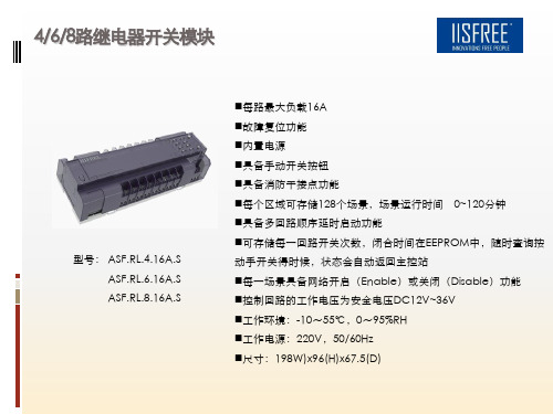
工作电源:220V,50/60Hz
尺寸:198W)x96(H)x67.5(D)
4/6路自锁负载反馈型继电器
每路最大负载20A
具备过零断开技术 故障复位功能 内置电源
具备手动开关按钮
具备消防干接点功能 具备机械自锁继电器装置,停电切换的状态下可保持继电器开 关状态不变 可测量每回路电流值,并传送到中央监控电脑,故障复位功能 型号: ASF.RL.4.20AZSF.S ASF.RL.6.20AZSF.S 每个区域可存储128个场景,每个场景下任何一个 回路延迟执行 时间为655.35秒 触点寿命≥10万次 收到总线场景命令后,可立即返回执行完成后各回路的实际电 流值 每一场景具备网络开启(Enable)或关闭Disable)功能 工作环境:-10~55℃,0~95%RH 工作电源:220V,50/60Hz
输入电源:12Vdc/24Vdc±10% 整机无负载功耗:4 W 环境条件:工作温度:-10℃~+55℃
型号:ASF.IM.26
工作湿度:20%~80%
储存温度:-40℃~+55℃ 储存湿度:10%~95% 外形尺寸:120mm(W)*86mm(H)*50mm(D) 存储量:200个场景 每个模块具有26个无源输入点 输入点可接翘板开关、复位开关、紧急按钮或红外开关 每个模块都具有网络开启及关闭功能 每个输入点都具有网络开启及关闭功能 每个输入点可以设置20个相关场景 每个输入点可以设置三种输入方式:按下发送场景 奇偶次按下发不同场景 按下、松开发不同场景
每个按键都有对应的LED输出,LED灯颜色可选
每个按键可以设置三种输入方式(按下发送场景、 奇偶次按下发不同场景、按下/松开发不同场景) 环境条件:环境温度:-10℃~55℃ 型号 : P26016 P26012 ASF.IP.7 六键控制面板 二键控制面板 7键面板
DM432 低噪声数字式步进驱动器 说明书
深圳市雷赛机电技术开发有限公司地址:深圳市南山区登良路25号天安南油工业区二幢三楼邮编:518052电话:*************(20线)传真:*************Email:***************网址:上海办事处北京办事处地址:上海市淞江区九亭镇九新公路地址:北京市朝阳门广渠门外大街8号76号嘉和阳光大厦9楼优士阁B座308室电话:************/64853687电话:************传真:************传真:************美国雷赛科技公司香港雷赛科技公司Address: 630Parkland Dive 地址:沙田火炭山尾街 31-41号Rochester Hills, Mi48307 USA 华乐工业中心 E 座 9 字楼 3 室Tel:1-248-608-6388 电话:852-2952 9114852-2952 9395DM432低噪声数字式步进驱动器使用手册版权所有不得翻印【使用前请仔细阅读本手册,以免损坏驱动器】目录一、产品简介 (2)1. 概述 (2)2. 特点 (2)3. 应用领域 (2)二、电气、机械和环境指标 (2)1. 电气指标 (2)2. 使用环境及参数 (3)3. 机械安装图(单位:毫米) (3)4. 加强散热方式 (3)三、驱动器接口和接线介绍 (3)1. 接口描述 (3)2. 控制信号接口电路 (4)3. 控制信号时序图 (5)4. 控制信号模式设置 (5)5. 接线要求 (5)四、电流、细分拨码开关设定和参数自整定 (5)1.电流设定 (5)2. 细分设定 (6)3. 参数自整定功能 (6)五、供电电源选择 (6)六、电机选配 (6)1. 电机选配 (6)2. 电机接线 (7)七、典型接线案例 (7)八、保护功能 (8)九、常见问题 (8)1. 应用中常见问题和处理方法 (8)2. 驱动器常见问题答用户问 (9)雷赛产品保修条款 (9)DM432低噪声低发热数字式步进驱动器一、产品简介1. 概述DM432是雷赛公司新推出的数字式步进电机驱动器,采用最新32位DSP技术,用户可以设置256内的任意细分以及额定电流内的任意电流值,能够满足大多数场合的应用需要。
ELS-432GWA中文资料
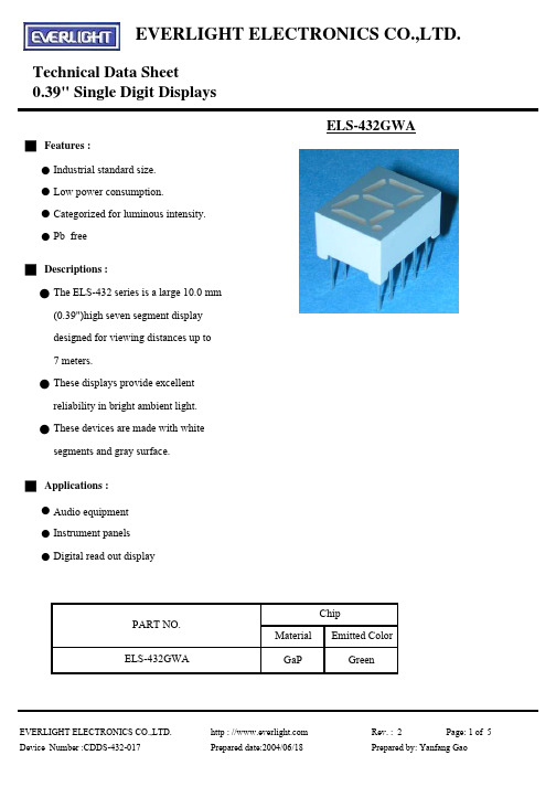
EVERLIGHT ELECTRONICS CO.,LTD.Technical Data Sheet0.39" Single Digit DisplaysELS-432GWA█ Features :●Industrial standard size. ●Low power consumption.●Categorized for luminous intensity.●Pb free█ Descriptions :●The ELS-432 series is a large 10.0 mm (0.39")high seven segment display designed for viewing distances up to 7 meters.●These displays provide excellent reliability in bright ambient light. ●These devices are made with white segments and gray surface.█ Applications :●Audio equipment ●Instrument panels ●Digital read out displayChipMaterialEmitted ColorGaPGreenEVERLIGHT ELECTRONICS CO.,LTD.http : // Rev. : 2Page: 1 of 5Device Number :CDDS-432-017Prepared date:2004/06/18Prepared by: Yanfang GaoELS-432GWAPART NO.EVERLIGHT ELECTRONICS CO.,LTD.Technical Data Sheet0.39" Single Digit DisplaysEVERLIGHT ELECTRONICS CO.,LTD. http : // Rev. : 2Page: 2 of 5 Device Number :CDDS-432-017Prepared date:2004/06/18Prepared by: Yanfang GaoEVERLIGHT ELECTRONICS CO.,LTD.Technical Data Sheet0.39" Single Digit DisplaysELS-432GWA█Absolute maximum ratings at Ta = 25℃:Parameter Symbol Rating Unit Reverse Voltage V R 5V Forward Current IF 30mA Operating Temperature Topr -40 to +85℃Storage Temperature Tstg -40 to +100℃Soldering Temperature Tsol 260 ± 5℃Power Dissipation Pd 100mW Peak Forward Current(Duty 1/10@ 1KH Z )I F (Peak)160mA█Electronic optical characteristics :ParameterSymbolMin.Typ.Max.UnitConditionLuminous Per segment1.053.20----IntensityPer decimal pointIv0.45 1.0----Peak Wavelength λp ----565----nm I F =20mA Dominant Wavelength λd ----570----nm I F =20mA Spectrum Radiation Bandwidth△λ----30----nm I F =20mA Forward Voltage V F 1.7 2.1 2.4V I F =20mA Reverse CurrentI R--------10µAV R =5VEVERLIGHT ELECTRONICS CO.,LTD. http : // Rev. : 2Page: 3 of 5Device Number :CDDS-432-017Prepared date:2004/06/18Prepared by: Yanfang GaomcdI F =10mAEVERLIGHT ELECTRONICS CO.,LTD. Technical Data Sheet0.39" Single Digit DisplaysELS-432GWA █ Typical Electro-Optical Characteristic Curves:EVERLIGHT ELECTRONICS CO.,LTD.http : // Rev. : 2Page: 4 of 5 Device Number :CDDS-432-017Prepared date:2004/06/18Prepared by: Yanfang GaoEVERLIGHT ELECTRONICS CO.,LTD. Technical Data Sheet0.39" Single Digit DisplaysELS-432GWA█ Reliability test items and conditions:NO Item Test ConditionsTestHours/CycleSample Size Ac/Re1Solder Heat TEMP : 260℃ ± 5 ℃ 5 SEC76 PCS0/1H : +85℃30min2Temperature Cycle∫ 5 min50 CYCLE76 PCS0/1L : -55℃30minH : +100℃5min3Thermal Shock∫ 10 sec50 CYCLE76 PCS0/1L : -10℃5min4High Temperature Storage TEMP : 100℃1000 HRS76 PCS0/1 5Low Temperature Storage TEMP : -55℃1000 HRS76 PCS0/1 6DC Operating Life IF = 10 mA1000 HRS76 PCS0/17High Temperature / HighHumidity85℃/85% RH1000 HRS76 PCS0/1EVERLIGHT ELECTRONICS CO.,LTD. http : // Rev. : 2 Page: 5 of 5 Device Number :CDDS-432-017Prepared date:2004/06/18Prepared by: Yanfang Gao。
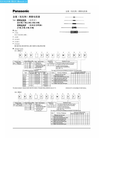
ERG2SG432E中文资料(PANASONIC)中文数据手册「EasyDatasheet - 矽搜」
, tolerance ±5 %, and package of radial taping.
例2:ERG型
1
2
3
4
5
6
7
8
9
10
11
12
ERG
2 SJW1 0 3E
Product Code
ERG
Metal Oxide Film Resistors
Power Rating at °7C0
12 0.5 W 1 1W 2 2W 3 3W 5 5W
(5) Resistance Range Type ERG :
10
Type ERX : 9.1
(6) Asfor the low resistance value range, "Z" isgiven to the part
number. (Refer to the explanation of part numbers.)
600
600
ERG(X)1S ERG(X)1F
1
ERG(X)2S ERG(X)2F
2
ERG(X)3S ERG(X)3F
3
ERG(X)5S ERG(X)5F
5
350
600
600
350
700
1000
350
700
1000
500
1000
1500
(1) Rated ContinuousWorking Voltage (RCWV) shall be determined from RCWV= Power Rating Resistance Value or Limiting Element
atc中文手册

CAT24WC256 是一个256K 位串行CMOS E2PROM 内部含有32768 个字节每字节为8 位
CATALYST 公司的先进CMOS 技术实质上减少了器件的功耗CAT24WC256 有一个64 字节页写缓冲器
该器件通过I2C 总线接口进行操作
管脚描述
管脚名称 功能
A0 A1 地址输入
置在接收到第一个数据字节后不发送应答信号从而避免寄存器区域被编程改写
读操作
CAT24WC256 读操作的初始化方式和写操作时一样仅把R/W 位置为1 有三种不同的读操作方式
立即/当前地址读选择/随机读和连续读
立即/当前地址读
的地址计数器内容为最后操作字节的地址加1 也就是说如果上次读/写的操作地址为N 则立即
2 在数据传送过程中当时钟线为高电平时数据线必须保持稳定状态不允许有跳变时钟线
为高电平时数据线的任何电平变化将被看作总线的起始或停止信号
起始信号
时钟线保持高电平期间数据线电平从高到低的钟线保持高电平期间数据线电平从低到高的跳变作为I2C 总线的停止信号
器件寻址
主器件通过发送一个起始信号启动发送过程然后发送它所要寻址的从器件的地址8 位从器件地
址的高5 位固定为10100 见图5 接下来的2 位A1 A0 为器件的地址位最多可以连接4 个器件
到同一总线上这些位必须与硬连线输入脚A1 A0 相对应从器件地址的最低位作为读写控制位1
表示对从器件进行读操作0 表示对从器件进行写操作在主器件发送起始信号和从器件地址字节后
读的地址从地址N+1 开始如果N=E 此处E=32767 则计数器将翻转到0 且继续输出数据CAT24WC256
接收到从器件地址信号后R/W 位置1 它首先发送一个应答信号然后发送一个8 位字节数据主
惠而浦系列4322089超大容量465独立燃气和电力系列说明书
CONSUMER SERVICES TECHNICALEDUCATION GROUP PRESENTSJOB AIDPart No. 4322089SUPER CAPACITY 465FREESTANDINGGAS & ELECTRIC RANGESFORWARDThis Job Aid will introduce the technician to the Whirlpool Ranges. This Job Aid is a reference guide for the experienced technician. It is not designed as a replacement to basic training. This Job Aid does not replace the Service Manual or the Use and Care Guide. It is designed to be used in conjunction with these manuals.OBJECTIVEThe objective of this Job Aid is to have the experienced appliance technician become familiar with the operation and service of the Whirlpool Ranges. It is designed as reference material and is not a replacement for basic training.WHIRLPOOL CORPORATION assumes no responsibility for any repair made on our products by anyone other than Authorized Factory Service Technicians.A-C-B-A-D-C-B-B-A-BCopyright 1996 Whirlpool CorporationTable of ContentsFive Key Benefits & Features............................................................................................Page 2 Warning Labels.................................................................................................................Page 3 Model & Serial Number Location......................................................................................Page 4 Serial Number Description................................................................................................Page 4 Gas Range Model Number...............................................................................................Page 5 Electric Range Model Number..........................................................................................Page 5 Models With Electronic Controls.......................................................................................Page 6 Oven Controls...................................................................................................................Page 7 Using The Oven Controls..................................................................................................Page 9 AccuSimmer™ Burner....................................................................................................Page 10 The Venturi System..........................................................................................................Page10 Gas Range Component Locations..................................................................................Page 11 Oven Door Removal........................................................................................................Page 12 Removing A Maintop.......................................................................................................Page 13 L.P. Conversion...............................................................................................................Page 14 Orifice Specifications.......................................................................................................Page 14 Oven Door Lock System.................................................................................................Page 16 Ignition System Operation...............................................................................................Page 17 Typical Gas Range Wiring Diagram................................................................................Page 20 Gas Range Strip Circuits.................................................................................................Page 21 Oven Door Lock System Current Flow............................................................................Page 22 The Oven Temperature Sensor......................................................................................Page 22 Electric Range Component Locations.............................................................................Page 23 Oven Thermal Fuse Location..........................................................................................Page 24 AccuBake™ Temperature Management System............................................................Page 24 Electric Range Wiring Diagram.......................................................................................Page 25 Electric Range Strip Circuits...........................................................................................Page 26 Confirmation Of Understanding.......................................................................................Page 27FIVE KEY BENEFITS & FEATURES1.The Largest Oven Capacity In The Industrya)The Super Capacity 465™ Range offers more oven space than any other range in theindustry—4.65 cubic feet.b)Large meals are never a problem with the spacious capacity.c)Save time by cooking multiple meals and freezing them for the busy days ahead.2.Consistent Cooking Resultsa)AccuSimmer™ burners on gas ranges provide precise low-heating for delicate sauces andchocolates (Models SF385 & SF395).b)Food cooks evenly throughout the oven cavity.c)Electronic controls maintain oven temperature swings within ±20˚F.d)AccuBake™ Triple Cycling Elements on electric models with EZ-Touch 200 & EZ-Touch300 oven controls.e)Custom Broil allows the selection of temperature from 300˚F to 525˚F (300˚F to 500˚F onelectric ranges) so that everything from fish to steaks broil perfectly (on all Touch Control models).3.Easy-To-Use Controlsa)Whirlpool EZ-Touch™ Electronic Controls offer the following innovative features:•One-Touch operation sets Bake at 350˚F, and Self-Clean for 3.5 hours.•Exclusive Preheat Countdown visually indicates the time required for oven preheating.The oven control beeps when the preset temperature is reached.•Child Lockout disables the control panel to prevent children from accidentally turning theoven on.•Easy to understand left-to-right programming logic.•Color-Keyed touch pads.4.Easy To Cleana)Spillguard™ Cooktop has raised edges to help contain spills. Porcelain surfaces wipeclean with a damp sponge.b)CleanTop™ Ranges offer radiant elements under a one-piece, smooth ceramic glasssurface for easy clean up.c)Seamless cooktop on coil ranges lifts easily for cleaning the burner box.d)Automatic door lock for self-clean ovens requires no external latch to lock the oven doorfor the Self-Clean cycle.5.Modern Designa)Stylish cabinet depth design offers a built-in look.b) A modern curved console and a one-piece solid handle are designed with no exposedscrews or unsightly trim.c) A hidden vent.d)200-degree rotation infinite flame setting valves on gas ranges (SF385 & SF395) offeroptional ergonomic, one-turn operation, while allowing precise burner management.e)Whirlpool “Family Look” styling compliments an entire kitchen of Whirlpool appliances.WARNING LABELSThis manual is intended for factory-service technicians only. We recommend that customers DO NOT service their own units, because of the complexity and risk of high-voltage electrical shock.The following information is used throughout this manual, and should be read carefully.MODEL & SERIAL NUMBER LOCATIONThe Model/Serial Number Plate is located behind the broiler/storage drawer.Model/Serial PlateThe serial number can be decoded by using the following example:SERIAL NUMBER: RF 36 50001R = Manufacturing Location (Tulsa, OK)F = Year of Manufacture (1996)36 = Week of Production (36th week)50001 = Sequence of RangeSERIAL NUMBER DESCRIPTIONGAS RANGE MODEL NUMBER MODEL NUMBER =ELECTRIC RANGE MODEL NUMBER MODEL NUMBER =MODELS WITH ELECTRONIC CONTROLSGas RangesThe following chart shows the gas range models with electronic controls:OVEN CONTROLWHIRLPOOL ROPER ESTATEK.E.T.SF350BEE**FGS335E**EZ-100SF360BEE**EZ-150SF315PEETGS325E**SF372BEE**SF375BEE**EZ-200SF325PEESF385PEE**EZ-300SF395LEE**** Self-Clean Model** Self-Clean ModelOVEN CONTROLWHIRLPOOL ROPER ESTATEK.E.T.RF350PXE**FES330E**RF354BXE**FES364EEZ-100RF360BXE**TES325E**RF364BXE**RF375BXE**EZ-150RF315PXE**RF372BXE**RF375PXE**RF376PXE**EZ-200RF324PXE RF325PXERF385PXE**RF386PXE**EZ-300RF395LXE**RF396LXE**Electric RangesThe following chart shows the electric range models with electronic controls:OVEN CONTROLSThe Super Capacity 465 ranges use one of the following five electronic controls:K.E.T. Single-Knob Control(Knob With Electronic Thermostat)This oven control includes: Bake Temperature settings with Broil and Clean, Oven On, Oven Heating, & Door Locked/Cleaning indicatorsEZ-Touch™ 100This oven control offers an electronic LED Display, Indicator Lights, Custom Broil, Auto Clean, Child Lockout, and Start Prompt (no Time-Of-Day function).EZ-Touch™ 150Adds a Time-Of-Day Clock, Color-Keyed Temperature and Clock/Timer Pads, Electronic Minute Timer and Signal.EZ-Touch™ 200Adds an Illuminated Vacuum Fluorescent Display, AccuBake Tempera-ture Management System, Separate Time/Temp Displays, and Inte-grated Light Touch Pad.EZ-Touch™ 300Adds Delay Cook and Off functions.USING THE OVEN CONTROLSTo set the various oven control functions, use the following procedures:ELECTRONIC TIME-OF-DAY CLOCK•Press CLOCK.•Press TEMP.•Press START.ELECTRONIC MINUTE TIMER AND SIGNAL•Press TIMER.•Press TEMP.•Press START.•To cancel or turn off the Timer, press TIMER twice.TO USE COOK TIME•Press COOK TIME.•Press HR & MIN.•Press START.TO USE STOP TIME•Press STOP TIME.•Press HR & MIN.•Press START.TO USE COOK TIME AND DELAY START TIME•Press COOK TIME.•Press HR & MIN.•Press START.•Press STOP TIME.•Press HR & MIN.•Press START.START PROMPT•Press START to begin the selected func-tion.CHILD LOCKOUT•Press and hold START for 5 seconds.TEMPERATURE ADJUSTMENT•Press and hold BAKE for 4 seconds.•Press TEMP UP or DOWN arrow.•Press START.FAHRENHEIT/CELSIUS CONVERSION•Press and hold the CUSTOM BROIL for 5seconds.ADJUSTABLE AUDIBLE SIGNAL•Press and hold STOP TIME for 5 sec-onds.CLOCK DISABLE•Press and hold CLOCK for 5 seconds.DEMO FEATURE•Press and hold TIMER SET for 5 seconds.PREHEAT COUNTDOWN TIMER AND SIGNAL•Press BAKE.•Press START.CUSTOM BROIL•Press CUSTOM BROIL •Press TEMP.•Press START.SELF-CLEAN COUNTDOWN TIMER•Press AUTO CLEAN.•Press START.CANCEL OR STOP•Press CANCEL.ACCUSIMMER ™ BURNERThe exclusive sealed gas venturi burners provide precise, even flame control so that each burner stays lit, even under sudden draft conditions. Airflow to the front and rear burners is adjusted at the front of the venturi by prying the slots open or closed, or by rotating the air shutters.BURNER BOXVENTURI OPENINGVENTTHE VENTURI SYSTEMThe AccuSimmer™ (right rear) burner is designed to provide 550 B.T.U.s for precise, low-heat cooking.ACCUSIMMER BURNERGAS RANGE COMPONENT LOCATIONSConventional BurnersSWITCH& IGNITORSealed BurnersOVEN DOOR REMOVALinsert nail or screw hererangehinge hangeroven dooroven door rangeLIFTROTATEhinge pins2.Close the oven door as far as the nails or screws will allow, lift the door off the two hinge pins, pull the door towards you so that the hinges are free of the slots, and remove it.The procedure for removing the oven door is the same for both gas and electric ranges. The door removal is different from previous ranges. To remove the door:1.Open the door half way and install a nail or a screw into the hinge hanger holes onboth sides of the door.REMOVING A MAINTOP1.Push the front of the maintop to the left and lift the left corner, then unclip and lift theother corner, and raise the front of the maintop.2,Slide the maintop to the right and remove the left hinge pin from the hinge bracket, then free the right hinge pin from its bracket, and remove the maintop.L.P. Conversion Kits will be shipped with the product. Kits include four top burner orifice spuds. The kit numbers are as follows:Kit #3196473—Sealed Burner Models•(2) #65 spuds–8500 B.T.U. (brass)•(1) #68 spud–6500 B.T.U. (black)•(1) .7 mm spud–5500 B.T.U. (nickel)notchesL.P.NaturalL.R.7500L.F.9500R.F.9500R.R.6500brass nickelbrass black manifoldRemove & replace orifice spuds with the same color spudsKit #3196471—Open Burner Models•(4) #66 spuds (8000 B.T.U. each).brass brassbrass brass L.F.9000L.R.9000R.F.9000manifold SUGGESTED DRILL SIZE 1.45 MM NO. 65NO. 55NO. 681.2 MM .7 MM NO. 54NO. 66COLOR BRASS BRASS BLACK BLACK NICKEL NICKEL BRASS BRASSSTAMPINGNAT L.P.NAT L.P.NAT L.P.NAT L.P.BTU RATING9,5008,5007,5006,5006,5005,5009,0008,000SPUD KIT NUMBER 319647131964733196474SPUD #& QTY.3196211 (4)3196450 (2)3196335 (1)3196336 (1)3196643 (4)DESCRIPTIONL.P. Conversion (Open Burner)L.P. Conversion (Sealed Burner)Nat. Gas Spud Kit (Open Burner)ORIFICE SPECIFICATIONSTurn the orifice hoods on the oven burner(s) down 2-1/2 - turns.L.P. GAS:RegulatorL.P. GasNatural GasL.P. GASNATURAL GAS WASHERCAPOVEN DOOR LOCK SYSTEMLATCH IS UP AND DOOR IS LOCKEDSOLENOID PLUNGER IS EXTENDEDThe oven door lock system uses a solenoid-activated, push-push mechanism. The oven door will lock as soon as it is closed and the CLEAN function is programmed into the Electronic Oven Control (EOC). When the solenoid is activated, the plunger extends, and the actuator rod moves the latch to lock the door.After the CLEAN cycle is completed and the temperature inside the oven cavity falls below 500˚F,the latch solenoid relay closes and activates the door lock solenoid. The solenoid plunger retracts,and actuator rod pulls the latch and unlocks the oven door.LATCH IS DOOR IS SOLENOIDIGNITION SYSTEM OPERATIONOHMS LAW:I = E/RAMPS = VOLTAGE DIVIDED BY RESISTANCEA cold ignitor has a high resistance. When the oven control relay closes—OHMSCurrent flows through the ignitor and the bimetal coil.OHMSHigh ignitor resistance causes low current flow through the bimetal coil. As the ignitor heats up, its resistance decreases.OHMS AMPSLower ignitor resistance increases the current flow through the bimetal coil. When the ignitor is fully heated, its resistance is low. Low resistance causes maximum current to flow through the bimetal coil (2.5 to 3.6 amps).OHMS AMPSAs the bimetal coil heats, it heats the bimetal arm inside the gas safety valve.LOWFLOWAs the bimetal arm heats, it bends and opens the gas safety valve outlet to the burner.HIGHFLOWThe gas at the burner is lit by the hot ignitor and a flame is produced.When the oven reaches its selected temperature, the oven control relay opens, and power is removed from the circuit. With no voltage applied, the ignitor and bimetal coil start to cool.NL1The bimetal arm cools, bends to its original position, and closes the gas safety valve.The burner flame is extinguished.BURNER L OWTYPICAL GAS RANGE WIRING DIAGRAM K.E.T., EZ-100 & EZ-150 ControlsWGAS RANGE STRIP CIRCUITS K.E.T., EZ-100 & EZ-150 ControlsOVEN CONTROLOVEN CONTROLOVEN CONTROL* PULSE 1 SECONDSELF-CLEAN CIRCUITOVEN DOOR LOCK SYSTEMCURRENT FLOWVoltage is supplied to the control transformer whenever the range is plugged in. Current flows from L1, through the transformer, to the neutral side of the line. When voltage is supplied to the EOCs Latch Solenoid Relay, current flows through the Latch Solenoid, to the neutral side of the line.OVEN CONTROL* PULSE 1 SECONDTHE OVEN TEMPERATURE SENSORThe oven temperature sensor is a “Resistance Temperature Detector” (RTD), and is composed of a stainless steel tube with a thin film of platinum at the end. It is located at the upper left rear corner of the oven cavity. The RTD is a nonadjustable assembly, but may be checked at room temperature, or at 350˚F. A sensor resistance of less than 550 ohms is regarded as a shorted sensor, and a resistance greater than 3000 ohms is regarded as an open sensor. When the oven control senses a resistance of less than 550 ohms, and greater than 3000 ohms, the bake and broil functions will be turned off.To test the oven temperature sensor, perform thefollowing steps:e an ohmmeter and set the range switch toR x 10.2.With no power applied, touch the leads of theohmmeter to the connector pins of the sensor(you do not have to separate the connectors).Depending upon the oven temperature, youshould obtain the corresponding readingshown in the chart:Temperature (˚F)Resistance (Ω) 32 ± 1.91000 ± 4.075 ± 2.51091 ± 5.3250 ± 4.41453 ± 8.9350 ± 5.41654 ± 10.8 450 ± 6.91853 ± 13.5 550 ± 8.22047 ± 15.8 650 ± 8.62237 ± 18.5 900 ± 13.62697 ± 24.4ELECTRIC RANGE COMPONENTLOCATIONSINDICATORMAINTOP)OVEN LIGHT • For a description and test procedure for the Oven Temperature Sensor, refer to the previous page.OVEN THERMAL FUSEElectric (Pyro)Gas (Pyro)Electric (Non-Pyro)Gas (Non-Pyro)Bake Preheat Time & Temperature Ranges170˚ - 245˚2 min. 30 sec.250˚ - 445˚4 min. 15 sec.450˚ - 500˚6 min. 30 sec.170˚ - 245˚ 4 min. 250˚ - 445˚ 10 min. 450˚ - 500˚ 15 min.170˚ - 245˚2 min. 30 sec.250˚ - 445˚4 min. 15 sec.450˚ - 500˚6 min. 30 sec.170˚ - 245˚ 4 min. 250˚ - 445˚ 10 min. 450˚ - 500˚ 15 min.Bake Preheat Relay“ON” Time Bake % = 100Broil % = 40Bake % = 100Bake % = 100Broil % = 40Bake % = 100Bake Relay “ON” Time Bake % = 60Broil % = 20Bake % = 100Bake % = 60Broil % = 20Bake % = 100Broil Relay “ON” Time Broil % = 100 Broil % = 100Broil % = 100Broil % = 100Clean Preheat Relay“ON” Time Bake % = 60Broil % = 40N.A.N.A.N.A.Clean Relay “ON” TimeBake % = 80Broil % = 70Bake % = 100N.A.N.A.The oven thermal fuse is located on the back of the range. A thermal fuse is used on electric models with EZ-200 and EZ-300 oven controls.Relay Cycling ChartThe AccuBake™ Temperature Management System provides better baking results. Both the Bake and Broil elements can cycle independently or together to maintain more even temperatures.The following “Relay Cycling Chart” shows how the relays operate the two elements to obtain various bake and broil temperatures.ACCUBAKE ™ TEMPERATUREMANAGEMENT SYSTEMELECTRIC RANGE WIRING DIAGRAM EZ-200 & EZ-300 Oven ControlsELECTRIC RANGE STRIP CIRCUITS EZ-200 & EZ-300 Oven ControlsCONFIRMATION OF UNDERSTANDING1.The oven door lock mechanism is aa)push-push design.b)push-pull design.c)dual-solenoid design.d)manually operated design.2.The oven door is removed bya)loosening the two screws at the inner door panel and lifting up.b)removing the oven side panel and loosening the retaining brackets.c)opening the door to the broil stop position, inserting screws or nails in the hingeholes and lifting the door, then rotating it forward.d)sliding the lower part of the door forward to release the hinges.3.The surface burners are converted to L.P. bya)adjusting the universal type hoods at the burner valves.b)replacing the spuds in the burner valves with L.P. spuds.c)adjusting the venturi at the burner valve.d)These burners cannot be converted to L.P.4. The oven cavity in the SC465 range line isa)the largest in the industry.b)the smallest in the industry.c)average size within the industry.d)within 5% of being the largest in the industry.5.AccuBake in the electric range line indicatesa)the bake and broil elements are controlled by sensitive percentage switches.b)the oven temperature is held to within 5 degrees of the set temperature.c)the oven rack position is no longer important.d)the bake and broil elements will cycle independently.6.EZ-Touch indicates thea)feel of the oven door handle.b)operation of the surface burner knobs.c)programming of the electronic oven control.d)None of the above.7.The sealed gas burner venturi can be adjusted bya)loosening the screw at the slide cover and turning the cover to the desired setting.b)prying the venturi slot open with a flat-bladed screwdriver.c)replacing the venturi assembly with an L.P. venturi assembly.d)Sealed gas burners do not have venturi adjustments.8.All SC465 ranges utilize an oven thermal fuse.a)Trueb)False9.On ranges using the K.E.T., EZ-Touch 100, and EZ-Touch 150 oven controls, thebake and broil relays are both in the circuit whenever either the bake or broil elements are in use.a)Trueb)False10.The resistance in an oven burner ignitor in the gas models is relatively low when cold,then increases as the ignitor heats.a)Trueb)FalseLENGTH OF WARRANTYFULL ONE YEAR WARRANTYFrom Date of Purchase.WARRANTYWHIRLPOOL WILL PAY FOR:FSP ® replacement parts and repair labor to correct defects in materials or workmanship. Service must be provided by an authorized Whirlpoolservice company.WHIRLPOOL WILL NOT PAY FOR:A.Service calls to:1.Correct the installation of the range.2.Instruct you how to use the range.3.Replace house fuses or correct house wiring or plumbing.4.Replace owner-accessible light bulbs.B.Repairs when range is used in other than normal, single family household use.C.Pickup and delivery. Your range is designed to be repaired in the home.D.Damage to your range caused by accident, misuse, fire, flood, acts of God, or use of products not approved by Whirlpool.E.Repairs to parts or systems caused by unauthorized modifications made to the appliance. WHIRLPOOL WILL NOT PAY FOR:A.Service calls to:1.Correct the installation of the range.2.Instruct you how to use the range.3.Replace house fuses or correct house wiring or plumbing.4.Replace owner-accessible light bulbs.B.Repairs when range is used in other than normal, single family household use.C.Pickup and delivery. Your range is designed to be repaired in the home.D.Damage to your range caused by accident, misuse, fire, flood, acts of God, or use of products not approved by Whirlpool.E.Ceramic cooktop only; Repairs to CLEANTOP ceramic cooktop if it has not been cared for as recommended in the Use and Care Guide.F.Repairs to parts or systems caused by unauthorized modifications made to the appliance.Ceramic cooktop only; FSP replacement parts and repair labor for CLEANTOP™ceramic cooktop to the original purchaser of this product.Whirlpool warrants that:– The ceramic cooktop will not discolor– The ceramic cooktop pattern will not wear off– The rubber seal between the ceramic cooktop and porcelain edge will not crack– The ceramic cooktop will not crack due to thermal shock– The surface units will not burn out Whirlpool ® Electric RangeWHIRLPOOL WILL PAY FOR:FSP ® replacement parts and repair labor to correct defects in materials or work-manship. Service must be provided by an authorized Whirlpool service company.LENGTH OF WARRANTYFULL ONE-YEAR WARRANTYFrom Date of Purchase. FULL FIVE-YEAR WARRANTY From Date of Purchase.WHIRLPOOL CORPORATION SHALL NOT BE LIABLE FOR INCIDENTAL OR CONSEQUENTIAL DAMAGES. Some states do not allow the exclusion or limitation of incidental or consequential damages, so this exclusion or limitation may not apply to you. This warranty gives you specific legal rights, and you may also have other rights which vary from state-to-state.Outside the United States, a different warranty may apply. For details, please contact your authorized Whirlpool distributor or military exchange.If you need service first see the “Troubleshooting” section of the Use and Care Guide. After checking “Troubleshooting,” additional help can be found by checking the “Requesting Assistance or Service” section, or by calling our Consumer Assistance Center telephone number, 1-800-253-1301, from anywhere in the U.S.A.® Registered Trademark/TM of Whirlpool Corporation.Whirlpool ® Gas RangeMaking your world a little easier.。
CBM432 产品手册说明书

专芯发展•用芯服务•创芯未来产品特点●精确到1.24V 的参考电压●保证0.5%的参考电压容差●吸收电流能力,80µA 至100mA ●快速开启●可调输出电压,Vo=VREF 至18V ●0.2Ω典型输出阻抗●SOT-23,SOT-89封装产品应用●PC 主板●电压适配器●开关电源●充电器产品描述CBM432是一个三端可调调节器系列,在适用的温度范围内具有保证的热稳定性。
输出电压可以设置为Vref(大约1.24V)和18V 之间的任何值,有两个外部电阻。
这些器件具有典型的动态输出阻抗0.2Ω。
有源输出电路提供了非常锐利的开启特性,使这些器件在许多应用中成为齐纳二极管的极好替代品。
CBM432可在-40℃至+125℃范围内工作。
目录产品特点 (1)产品应用 (1)产品描述 (1)目录 (2)引脚分配及定义 (3)绝对最大额定值 (4)符号 (5)原理图 (5)等效原理图 (5)电气特性 (6)测试电路 (8)典型应用 (10)应用信息 (14)封装尺寸及结构 (17)SOT-23-3 (17)SOT-89-3 (18)包装/订购信息 (19)引脚分配及定义SOT23-3SOT89-3编号符号(SOT23-3/SOT89-3)类型(输入/输出)功能1REFERENCE输入基准电压引脚2ANODE输出正极3CATHODE输入/输出负极绝对最大额定值符号参数额定值单位V KA阴极电压20VI K持续阴极电流范围100mAI REF基准电流范围3mAT J结温范围-40to150℃T STG存储温度范围-60to150℃符号原理框图等效原理图电气特性符号参数测试条件最小值典型值最大值单位V REF基准输入电压V KA =V REF ,I K =10mA(图.1)1.234 1.240 1.246VV REF(DEV)过满载温度范围基准输入电压偏差T A =全温度范围(see Note1)V KA =V REF ,I K =10mA(图.1)1025mV△V REF /△V KA基准电压变化与阴极电压变化的比值I K =10mA,V KA =18V toV REF (图.2)-1-2.7mV/VI REF基准输入电流I K =10mA,R 1=10kΩR 2=∞(图.2)0.250.5μAI REF(DEV)过满载温度范围基准输入电流偏差T A =全温度范围(see Note1)R 1=10kΩ,R 2=∞I K =10mA(图.2)0.050.3μAI K (off)关闭状态阴极电流V REF =0V,(图.3)V K =18V 0.040.5μAZka 动态输出阻抗V ka=V REF,I K =1mA to 100mA F≤1KHz(图.1)0.20.4ΩI K(MIN)最小工作电流V ka=V REF (图.1)6080μA提示:1.偏离参量∆Vref 由在应用时满载工作环境温度范围的最大值和最小值差别来定义。
亚利桑特技术N432A热敏电阻功率表数据手册说明书
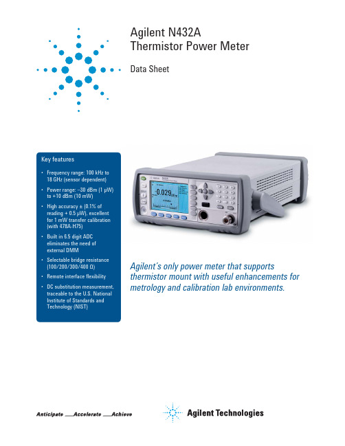
Agilent N432AThermistor Power MeterData SheetAgilent’s only power meter that supports thermistor mount with useful enhancements for metrology and calibration lab environments.Why Agilent’s Power Meters and Sensors?Reliable, high-performing solutionsEvery power meter and sensor from Agilent consistently delivers great results.A sure investment for many years to comeCode-compatibility between power meters reduces the need for re-coding. Notonly that, all Agilent power meters are backward-compatible with most legacypower sensors.One specific application: One right solutionAgilent offers a wide selection of power meters and sensors for practicallyall application needs—wireless communications, radar pulse measurements,component test, and more.Global network supportNo matter where you are, Agilent is committed to giving you the 24-hoursupport you need regarding our products, applications, or services.Agilent’s power meters have long beenrecognized as the industry standard forRF and microwave power measurements.We Listened to the Industry, Then Delivered a Better and Easier Replacement Solution for the Legacy 432A Analog Power MeterAs today’s power measurementsbecome more complex, it is increas-ingly difficult to make reliable, accu-rate power measurements. For morethan 40 years, you’ve depended onAgilent’s 432A analog power meter,used with temperature compensatedthermistor sensors to provide highaccuracy over a wide temperaturerange.LXI Class-C compliant N432AThe N432A is a single-channel, aver-age RF power measurement meterthat supports thermistor sensors. TheN432A has the capability to measureand display average power, RF bridgevoltages (VRF0 and VRF1), compensationbridge voltages (VCOMP0 and VCOMP1),V 0, and V1. It is also provided with aset of features such as zeroing and a built-in self-test.Developed using LXI technology,the N432A is an LXI Class-C compli-ant instrument.1 The N432A basic configuration consists of two key sections: bridge and meter logic. When a compatible thermistor sensor is connected to the N432A, the RF and compensation bridge circuitsare formed in the bridge section. VRF ,which is the voltage at the top of the RF bridge, is responsive to both input RF power and ambient temperaturechanges. On the other hand, VCOMP,which is the voltage at the top of thecompensation bridge, is responsiveonly to ambient temperature changes.The VRFand VCOMPvalues are used incalculating the RF power. Meanwhile,the meter logic section processes VRFand VCOMPto produce a meter currentproportional to RF power.In general, the N432A is aneasy-to-use instrument, especiallywith the availability of an integratedWeb browser that provides a con-venient way to view and modify theinstrument network configuration.Besides the LAN interface, the N432Aalso supports industry standard GPIBand USB interfaces for measurementautomation.Today, the Agilent N432A digitalthermistor power meter, loaded withenhancements, including a colordigital display, and intuitive frontpanel interface will continue supportyour measurement needs with greatercapability and expanded functionality.Best of all, you can get these extrasat just a fraction of the price of thelegacy 432A.1. LXI, an acronym for LAN eXtension for Instrumentation, is an instrument standard for devices that use the Ethernet (LAN) as their primarycommunication interface.High accuracy—no thermoelectric errorThe high accuracy ± (0.1% of reading + 0.5 μW) over a wide temperature range featured in the legacy 432A power meter is also included in the N432A, making it excellent for 1 mW transfer calibration (with 478A-H75/ H76*). Accuracy can be maintained on even the most sensitive range as the error due to thermoelectric effect is reduced to a negligible level.* 478-H75/H76 has a maximum SWR of1.05 at 50 MHz Sensor compatibilityThe N432A is compatible with the Agilent 478A and 8478B thermistor sensors. The following table lists the frequency range and operating resistance for these two sensors:478A0.01 to 10200478A Option H630.000001 to 1200478A Option H750.001 to 1200478A Option H760.001 to 12008478B0.01 to 18200For further information on the thermistor sensors, refer to the respective manuals.Take a Closer LookN432A front panelN432A back panelHigh-resolution color LCD display for easy viewing of test results Display key allows selection of the display format for the active window (single/split screen)Display key allows selection of the display mode (windowed, expanded, or full-screen) of numeric measurementsHard keys provide quick access to the most frequently used functions, such as System, Trigger, and Acquisition, etc.Channel sensor connectorArrow keys enable navigation of parameter entry screens, values selection, and entering of textSoft keys provide menu selection Numeric keypad for easy entry of numeric valuesPower reference of 1 mW (0 dBm)Ground connectorDC recorder outputs (DC voltage corresponds to the power level of the channel input)V RF and V COMP output terminals for calibrating the N432A and for precision power measurementsLine power accepts voltage with automatic range selectionGo beyond GPRB with USB and LAN/LXI-C interfaceSpecifications and CharacteristicsSpecifications describe the instrument’s warranted performance and apply after a 30 minute warm-up.These specifications are valid over its operating/environmental range unless otherwise stated and after performing a zero and calibration procedure.Supplemental characteristics (shown in italics) are intended to provide additional information, useful in applying the instru-ment by giving typical (expected), but not warranted performance parameters. These characteristics are shown in italics or labeled as “typical”, “nominal” or “approximate”.Frequency range100 kHz to 18 GHz, sensor dependentPower range–30 to +10 dBm (1 μW to 10 mW), thermistor-sensor dependentCompatible power sensors• Agilent 478A thermistor sensor (100 kHz to 10 GHz, with option H63)• Agilent 8478B thermistor sensor (10 MHz to 18 GHz)Meter power accuracyPower absolute accuracy± (0.1% of reading + 0.5 μW)Meter voltage accuracy(1-year reference specifications)V RF and VCOMPV 0 and V123 °C ± 5 °C: ± (0.0035% + 50 µV) [reading + range]23 °C ± 5 °C: ± (0.0040% + 25 µV) [reading + range]Bridge resistance100, 200, 300, or 400 Ω (user selectable) Display unitsPowerRelativeV RF , VCOMP, V, and V1Bridge resistance Watts (W) or dBm Percent (%) or dB VDC and mVDC OhmDisplay resolutionPowerDefault resolution VoltageBridge resistance Selectable resolution of: 1.0, 0.1, 0.01 and 0.001 dB in logarithmic mode, or 1, 2, 3, and 4 significant digits in linear mode0.01 dB in logarithmic mode or three digits in linear mode6.5-digit resolution6.5-digit resolutionAccessed by key entry Either hard keys, or soft key menu, and programmableZero Zeros the meter. (Power reference calibrator is switched off during zeroing)Frequency Entered frequency range is used to interpolate the calibration factors table. Frequency range from1 kHz to 999.9 GHzBridge resistance type Setting the bridge resistance, user-selectable Rmeasure (factory set) or Ruser (measured by user) Cal factor Sets the cal factor versus frequency for the calibration factor for power sensor. Range: 1.00% to150.00%, in 0.01% increments. Cal factor can be set from either CF table or single entry CF Relative Displays all successive measurements relative to the last displayed valueOffset Allows power measurements to be offset by –100 to +100 dB, settable in 0.001dB increments, tocompensate for external loss or gain. Offset table can be set from either CF table or single entryCFSave/recall Store up to 10 instrument states via the save/recall menuMeasurement averaging Selectable from 4 to 128Duty cycle Duty cycle values between 0.001 to 99.999%, in 0.001% increments, can be entered to display apeak power representation of measured power. The following equation is used to calculate thedisplayed peak power value: peak power = measured power/duty cycleLimits High and low limits can be set in the range –150.000 to +230.000 dBm, in 0.001 dBm increments Preset default values dBm mode, relative off, power reference off, duty cycle off, offset off, frequency 50 MHz,measurement averaging 16, free runDisplay Color display with selectable single and split screen formats are available. User selectable ondigital measurement type or analog scale presentation1 mW (0 dBm) power referenceAccuracy (for two years)SWR 1.0 mW (0.0 dBm), 50 MHz from type N (f) connector on the front panel, for power meter/sensor function check.± 0.4% (25 ± 10 ºC)± 1.2% (0 to 45 ºC)1.06 maximumDimensionsThe following dimensions exclude front and rear protrusions:212.6 mm W x 88.5 mm H x 348.3 mm D (8.5 in x 3.5 in x 13.7 in)WeightModel Net ShippingN432A 3.6 kg (8.0 lb) 8.2 kg (18.1 lb)Rear panel connectorsV RF output V RF BNC terminal outputs the RF bridge voltage, used to connect to external DMM for more precise power measurementV COMP output V COMP BNC terminal outputs the compensation bridge voltage, used to connect to external DMM for more precise power measurementRecorder outputAnalog 0 to 1 V, 1 kΩ output impedance, BNC connector GPIB, USB 2.0 and 10/100BaseT LAN Interfaces to allow communication with an external controller GroundBinding post, accepts 4 mm plug or bare wire connection Line powerInput voltage range Input frequency range 100 – 240 VAC, automatic selection 220 – 240 V ±10%50 – 60 Hz, 400 Hz 400 Hz (100 – 120 Vac)Power requirement70 VAElectromagnetic compatibility Complies with the essential requirements of EMC Directive (2004/108/EC) as follows:• IEC61326-1:2005 / EN61326-1:2006• CISPR11:2003 / EN55011:2007 (Group 1, Class A)The product also meets the following EMC standards:• Canada: ICES/NMB-001:2004• Australia/New Zealand: AS/NZS CISPR 11:2004Product safety This product conforms to the requirements of the following safety standards:• IEC 61010-1:2001 / EN 61010-1:2001• CAN/CSA-C22.2 No.61010-1-04• ANSI/UL61010-1:2004Low voltage directive This product conforms to the requirements of European Council Directive “2006/95/EC”Operating environmentTemperatureMaximum humidity Minimum humidity Maximum altitude 0 °C to 45 °C95% at 40 °C (non-condensing) 15% at 40 °C (non-condensing) 4,600 m (15,000 ft)Storage conditionsNon-operating storage temperature Non-operating maximum humidity Non-operating maximum altitude –40 °C to +70 °C90% at 65 °C (non-condensing) 4,600 m (15,000 ft)Remote programmingInterfaceCommand language GPIB compatibility GPIB, USB, and LAN interfaces operates to IEEE 488.2 standard SCPI standard interface commandsSH1, AH1, T6, TE0, L4, LE0, SR1, RL1, PP1, DC1, DT1, C0Ordering InformationN432A Thermistor power meterStandard shipped accessories• Thermistor sensor adaptor cable 1.5 m* (5 ft)• Power cord (country dependant)• USB adaptor cable• Agilent N432A thermistor power meter product reference CD-ROM• Envelope—calibration certificate• IO libraries media suiteWarranty• Standard 1-year, return-to-Agilent warranty and service plan• 3 months for standard shipped accessories478A-H13Frequency range 100 kHz to 1 GHz, with maximum SWR 1.8 to 300 KHz, 1.3 to 1 GHz. Include 13frequency points Standard Lab calibration478A-H55Frequency range 1 MHz to 1 GHz, with maximum SWR 1.3478A-H63Frequency range 100 kHz to 1 GHz, max SWR 1.8 to 300 kHz, 1.3 to 1 GHz478A-H72Frequency range 1 MHz to 1 GHz, with maximum SWR 1.2478A-H73Frequency range 1 MHz to 100 MHz, with maximum SWR 1.1, except 1.05 at 50 MHz478A-H75Frequency range 1 MHz to 1 GHz, max SWR 1.3 except 1.05 at 50 MHz478A-H76Frequency range 1 MHz to 1 GHz, max SWR 1.3 except 1.05 at 50 MHz. Standard lab calibration at50 MHz478A-H83Frequency range 1 MHz to 1 GHz, with maximum SWR 1.3, except 1.05 at 50 MHz Include 8frequency points Standard Lab calibration478A-H93Frequency range 1 MHz to 1 GHz, with maximum SWR 1.3, except 1.05 at 50 MHz Include 2frequency points Standard Lab calibration8478B-H01Frequency range 10 MHz to 18 GHz, with maximum SWR 1.05 at 50 MHz8478B-H27Frequency range 10 MHz to 18 GHz. Include Standard Lab calibration at 9 MHzN4998A Thermistor sensor adaptor cable 1.5 m (5 ft)N4998B Thermistor sensor adaptor cable 3 m (10 ft)N4998C Thermistor sensor adaptor cable 6.1 m (20 ft)N432A-908Rackmount kit with 1 unit with blank filler includedN432A-909Rackmount kit with 2 units side-by-sideN432A-OBK English language user guide and English programming guideN432A-ABJ Japanese user guide and English programming guideN432A-0B1English language user guide and installation guideN432A-0BF English language programming guideN432A-A6J Certificate of compliance calibration - ANSI/NCSL Z540N432A-1A7Compliant calibration test data - ISO17025* The 1.5 m (5 ft) standard cable can be replaced with a 3 or 6.1 m (10 or 20 ft) cable, charges apply/find/N432ALAN eXtensions for Instruments puts the power of Ethernet and the Web inside your test systems. Agilent is a founding member of the LXI consortium.Agilent Channel Partners/find/channelpartners Get the best of both worlds: Agilent’s measurement expertise and product breadth, combined with channel partner convenience.For more information on AgilentTechnologies’ products, applications or services, please contact your local Agilent office. The complete list is available at:/find/contactus Americas Canada (877) 894 4414 Brazil (11) 4197 3600Mexico 01800 5064 800 United States (800) 829 4444Asia Pacifi c Australia 1 800 629 485China 800 810 0189Hong Kong 800 938 693India 1 800 112 929Japan 0120 (421) 345Korea 080 769 0800Malaysia 1 800 888 848Singapore 180****8100Taiwan 0800 047 866Other AP Countries (65) 375 8100Europe & Middle East Belgium 32 (0) 2 404 93 40 Denmark 45 45 80 12 15Finland 358 (0) 10 855 2100France 0825 010 700**0.125 €/minute Germany 49 (0) 7031 464 6333 Ireland 1890 924 204Israel 972-3-9288-504/544Italy 39 02 92 60 8484Netherlands 31 (0) 20 547 2111Spain 34 (91) 631 3300Sweden 0200-88 22 55United Kingdom 44 (0) 118 927 6201For other unlisted countries: /find/contactus(BP-3-1-13)Product specifications and descriptions in this document subject to change without notice.© Agilent Technologies, Inc. 2013Published in USA, March 25, 20135990-5740EN/qualityAdvancedTCA ® Extensions forInstrumentation and Test (AXIe) is an open standard that extends theAdvancedTCA for general purpose and semiconductor test. Agilent is a founding member of the AXIe consortium.PCI eXtensions for Instrumentation (PXI) modular instrumentation delivers a rugged, PC-based high-performance measurement and automation system.Quality Management SystemQuality Management Sys ISO 9001:2008DEKRA Certified /find/myagilentA personalized view into the information most relevant to you.myAgilent my Agilent/find/AdvantageServices Accurate measurements throughout the life of your instruments.Agilent Advantage ServicesThree-Year Warranty/find/ThreeYearWarranty Agilent’s combination of product reliability and three-year warranty coverage is another way we help you achieve your business goals: increased confidence in uptime, reduced cost of ownership and greater convenience.。
TS432I资料
TS432IAdjustable Precision Shunt RegulatorTO-92SOT-23SOT-25General DescriptionThe TS432I/432AI/TS432BI is a three-terminal adjustable shunt regulator with specified thermal stability. The output voltage may be set to any value between Vref (approximately 1.24V) and 18V with two external resistors. The TS432I/432AI/TS432BI has a typical output impedance of 0.05Ω. Active output circuitry provides a very sharp turn-on characteristic, making the TS432I/432AI/TS432BI excellent replacement for zener diode in many applications.Ordering InformationPart No.PackagePackingTS432x IT B0 TO-92 1Kpcs / Bulk TS432x IT A3 TO-92 2Kpcs / Ammo TS432x IX RF SOT-23 3Kpcs / 7” Reel TS432x IX5 RF SOT-253Kpcs / 7” Reel Note: Where xx denotes voltage tolerance Blank: ±2% A: ±1% B: ±0.5%Features● Precision Reference Voltage TS432I – 1.24V±2% TS432AI – 1.24V±1% TS432BI – 1.24V±0.5%● Minimum Cathode Current for Regulation: 20uA(typ.) ● Equivalent Full Range Temp. Coefficient: 50ppm/ ºC ● Programmable Output Voltage up to 18V ● Fast Turn-On Response● Sink Current Capability of 80uA to 100mA ● Low Dynamic Output Impedance: 0.2Ω ● Low Output NoiseApplication● Voltage Monitor ● Delay Timmer● Constant –Current Source/Sink ● High-Current Shunt Regulator ● Crow Bar●Over-Voltage / Under-Voltage ProtectionBlock DiagramAbsolute Maximum Rating (Ta = 25 oC unless otherwise noted)ParameterSymbolLimitUnitCathode Voltage (Note 1) Vka 18 V Continuous Cathode Current Range Ik 100 mA Reference Input Current Range Iref 3 mA Power Dissipation TO-92 SOT-23 SOT-25 Pd 0.625 0.350.35WJunction Temperature T J +150 o C Operation Temperature Range T OPER -40 ~ +85 oC Storage Temperature Range T STG -65 ~ +150 o CNote 1: Voltage values are with respect to the anode terminal unless otherwise noted.Note 2: Rating apply to ambient temperature at 25oCPin Definition:1. Reference2. Cathode3. AnodePin Definition:1. Reference2. Anode3. CathodePin Definition: 1. N/C 2. N/C * 3. Cathode 4. Reference 5. Anode* (pin 2 is connect to substrate and must be connected to Anode or left open)TS432IAdjustable Precision Shunt RegulatorRecommend Operating ConditionParameterSymbolLimitUnitCathode Voltage (Note 1)Vka 18 V Continuous Cathode Current RangeIk100mARecommend Operating ConditionParameterSymbo Test ConditionsMinTypMaxUnitTS432I1.215 1.264 TS432AI 1.227 1.252 Reference voltageTS432BIVrefVka =Vref, Ik=10mA (Figure 1)Ta=25 oC1.233 1.2401.246 VDeviation of reference input voltage∆Vref Vka =Vref, Ik=10mA Ta= full range (Figure 1)-- 10 25 mV Radio of change in Vref to change in cathode Voltage ∆Vref/∆VkaIka=10mA, Vka = 18V to Vref(Figure 2)-- -1.0 -2.7 mV/V Reference Input current IrefR1=10K Ω, R2=!, Ika=10mATa= full range (Figure 2)-- 0.25 0.5 uA Deviation of reference input current, over temp. ∆IrefR1=10K Ω, R2=!, Ika=10mATa= full range (Figure 2) -- 0.04 0.08 uA Off-state Cathode Current Ika(off) Vref=0V (Figure 3), Vka=18V-- 0.125 0.5 uA Dynamic Output Impedance|Zka|f<1KHz, Vka=VrefIka=1mA to 100mA (Figure 1)--0.20.4ΩMinimum operating cathodecurrentIka(min) Vka=Vref (Figure 1) -- 60 80 uA* The deviation parameters ∆Vref and ∆Iref are defined as difference between the maximum value and minimum value obtained over the full operating ambient temperature range that applied.* The average temperature coefficient of the reference input voltage, αVref is defined as:Where: T2-T1 = full temperature change.αVref can be positive or negative depending on whether Vref Min. or Vref Max occurs at the lower ambienttemperature. Example: ∆Vref=7.2mV and the slope is postive, Vref=1.241V at 25o C, ΔT=125 oC* The dynamic impedance Z KA is defined as:* When the device operating with two external resistors, R1 and R2, (refer to Figure 2) the total dynamic impedance of the circuit is given by:TS432IAdjustable Precision Shunt RegulatorTest CircuitsFigure 1: Vka = VrefFigure 2: Vka > VrefFigure 3: Off-State CurrentAdditional Information – StabilityWhen The TS432I/432AI/432BI is used as a shunt regulator, there are two options for selection of C L , are recommended for optional stability:A) No load capacitance across the device, decouple at the load.B) Large capacitance across the device, optional decoupling at the load.The reason for this is that TS432I/432AI/432BI exhibits instability with capacitances in the range of 10nF to 1uF (approx.) at light cathode current up to 3mA (typ). The device is less stable the lower the cathode voltage has been set for. Therefore while the device will be perfectly stable operating at a cathode current of 10mA (approx.) with a 0.1uF capacitor across it, it will oscillate transiently during start up as the cathode current passes through the instability region. Select a very low capacitance, or alternatively a high capacitance (10uF) will avoid this issue altogether. Since the user will probably wish to have local decoupling at the load anyway, the most cost effective method is to use no capacitance at all directly across the device. PCB trace/via resistance and inductance prevent the local load decoupling from causing the oscillation during the transient start up phase.Note: if the TS432I/432AI/432BI is located right at the load, so the load decoupling capacitor is directly across it, then this capacitor will have to be ≤1nF or ≥10uF.Applications ExamplesFigure 4: Voltage MonitorFigure 5: Output Control for Three Terminal Fixed RegulatorTS432IAdjustable Precision Shunt RegulatorApplications Examples (Continue)Figure 6: Shunt RegulatorFigure 7: High Current Shunt RegulatorFigure 8: Series Pass RegulatorFigure 9: Constant Current SourceFigure 10: TRIAC CrowbarFigure 11: SCR CrowbarTS432IAdjustable Precision Shunt RegulatorApplications Examples (Continue)Vin Vout<VrefV+>Vref≈0.74VFigure 12: Single-SupplyComparator with Temperature-Compensated ThresholdFigure 13: Constant Current SinkFigure 14: Delay TimerTS432IAdjustable Precision Shunt RegulatorTypical Performance CharacteristicsTest Circuit for Voltage AmplificationFigure 14: Small-Signal Voltage Gain and Phase Shift vs. FrequencyTest Circuit for Reference ImpedanceFigure 15: Reference Impedance vs. FrequencyTS432IAdjustable Precision Shunt RegulatorTypical Performance CharacteristicsThe areas under the curves represent conditions that may cause the device to oscillate. For curves B, C, and D, R2 and V+ were adjusted to establish the initial V KA and I KA conditions with C L =0. V BATT and C L then were adjusted to determine the ranges of stability.Test Circuit for Curve ATest Circuit for Curve B, C and DFigure 16: Stability Boundary ConditionTest Circuit for Pulse Response, Ik=1mAFigure 17: Pulse ResponseTS432IAdjustable Precision Shunt RegulatorElectrical CharacteristicsFigure 18: Reference Voltage vs. TemperatureFigure 19: Reference Current vs. TemperatureFigure 20: Cathode Current vs. Cathode VoltageTS432IAdjustable Precision Shunt RegulatorTO-92 Mechanical DrawingMarking DiagramX = Tolerance Code(A = ±1%, B = ±0.5%, Blank = ±2%,) Y = Year Code M = Month Code(A =Jan, B =Feb, C =Mar, D =Apl, E =May, F =Jun, G =Jul, H =Aug, I =Sep, J =Oct, K =Nov, L =Dec) L = Lot CodeTO-92 DIMENSION MILLIMETERS INCHES DIM MIN MAX MIN MAX A 4.30 4.70 0.169 0.185 B 4.30 4.70 0.169 0.185 C 14.30(typ) 0.563(typ) D 0.43 0.49 0.017 0.019 E 2.19 2.81 0.086 0.111 F 3.30 3.70 0.130 0.146 G 2.42 2.66 0.095 0.105 H0.37 0.43 0.015 0.017TS432IAdjustable Precision Shunt RegulatorSOT-23 Mechanical DrawingMarking DiagramX = Device Code(D = TS432AI, E = TS432BI, F = TS432I,) 3 = SOT-23 package Y = Year Code M = Month Code(A =Jan, B =Feb, C =Mar, D =Apl, E =May, F =Jun, G =Jul, H =Aug, I =Sep, J =Oct, K =Nov, L =Dec) L = Lot CodeSOT-23 DIMENSION MILLIMETERS INCHES DIM MIN MAX MIN MAX. A 0.95 BSC 0.037 BSC A1 1.9 BSC 0.074 BSC B 2.60 3.00 0.102 0.118 C 1.40 1.70 0.055 0.067 D 2.80 3.10 0.110 0.122 E 1.00 1.30 0.039 0.051 F 0.00 0.10 0.000 0.004 G 0.35 0.50 0.014 0.020 H 0.10 0.20 0.004 0.008 I 0.30 0.60 0.012 0.024 J5º 10º 5º 10ºTS432IAdjustable Precision Shunt RegulatorSOT-25 Mechanical DrawingMarking DiagramX = Device Code(D = TS432AI, E = TS432BI, F = TS432I,) 5 = SOT-25 package Y = Year Code M = Month Code(A =Jan, B =Feb, C =Mar, D =Apl, E =May, F =Jun, G =Jul, H =Aug, I =Sep, J =Oct, K =Nov, L =Dec) L = Lot CodeSOT-25 DIMENSIONMILLIMETERS INCHES DIM MIN MAX MIN MAX. A+A1 0.09 1.25 0.0354 0.0492 B 0.30 0.50 0.0118 0.0197 C 0.09 0.25 0.0035 0.0098 D 2.70 3.10 0.1063 0.1220 E 1.40 1.80 0.0551 0.0709 E 1.90 BSC 0.0748 BSC H 2.40 3.00 0.09449 0.1181 L 0.35 BSC 0.0138 BSC Ө1 0º 10º 0º 10º S10.95 BSC 0.0374 BSCTS432IAdjustable Precision Shunt RegulatorNoticeSpecifications of the products displayed herein are subject to change without notice. TSC or anyone on its behalf, assumes no responsibility or liability for any errors or inaccuracies.Information contained herein is intended to provide a product description only. No license, express or implied, to any intellectual property rights is granted by this document. Except as provided in TSC’s terms and conditions of sale for such products, TSC assumes no liability whatsoever, and disclaims any express or implied warranty, relating to sale and/or use of TSC products including liability or warranties relating to fitness for a particular purpose, merchantability, or infringement of any patent, copyright, or other intellectual property right.The products shown herein are not designed for use in medical, life-saving, or life-sustaining applications. Customers using or selling these products for use in9 such applications do so at their own risk and agree to fully indemnify TSC for any damages resulting from such improper use or sale.。
Agilent E6432A VXI Microwave Synthesizer产品说明书
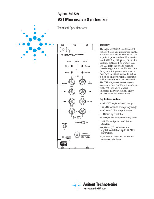
Agilent E6432AVXI Microwave Synthesizer Technical Specifications-40-60-80-100-120-1401101001K10K100K1MFrequency offset from carrier(Hz) 21Adding step attenuator (Option 1E1) degrades maximum output power by 1 dB, 2 to 20 GHz.2These I/Q specifications apply only after an internal calibration, and are valid for 10 days at a calibrationtemperature of ±5 degrees. These specifications include I/Q impairments of an Agilent Technologies ESG-D Series signalgenerator with Option UND as the baseband I/Q source.3Measured at 2 MS/s QPSK, root raised cosine filter with α= 0.35, 14 dB IF attenuation, maximumoutput level = 0 dBm, and ALC off.3Product specifications and descriptions in this document subject to change without notice.Copyright © 1998, 2000 Agilent Technologies Printed in U.S.A. 9/005968-1242EAgilent Technologies' Test and Measurement Support, Services, and AssistanceAgilent Technologies aims to maximize thevalue you receive, while minimizing your risk and problems. We strive to ensure that you get the test and measurement capabilities you paid for and obtain the support you need. Our extensive support resources and services can help you choose the right Agilent products for your applications and apply them successfully. Every instrument and system we sell has a global warranty. Support is available for at least five years beyond the produc-tion life of the product. Two concepts underlie Agilent's overall support policy: "Our Promise" and "Your Advantage."Our PromiseOur Promise means your Agilent test andmeasurement equipment will meet its advertised performance and functionality. When you are choosing new equipment, we will help you with product information, including realistic performance specifications and practical recommendations from experienced test engineers. When you use Agilent equipment, we can verify that it works properly, help with product operation, and provide basic measure-ment assistance for the use of specified capabili-ties, at no extra cost upon request. Many self-help tools are available.Your AdvantageYour Advantage means that Agilent offers a wide range of additional expert test and measurement services, which you can purchase according to your unique technical and business needs. Solve problems efficiently and gain a competitive edge by contracting with us for calibration, extra-cost upgrades, out-of-warranty repairs, and on-site education and training, as well as design, system integration, project management, and other profes-sional engineering services. Experienced Agilent engineers and technicians worldwide can help you maximize your productivity, optimize the return on investment of your Agilent instruments and systems, and obtain dependable measurement accuracy for the life of those products.For More Assistance with Your Test & Measurement Needs go to /find/assistOr contact the test and measurement experts at Agilent Technologies(During normal business hours)United States:(tel)180****4844Canada:(tel)187****4414(fax) (905) 206 4120Europe:(tel) (31 20) 547 2323(fax) (31 20) 547 2390Japan:(tel) (81) 426 56 7832(fax) (81) 426 56 7840Latin America:(tel) (305) 267 4245(fax) (305) 267 4286Australia:(tel) 1 800 629 485 (fax) (61 3) 9272 0749New Zealand:(tel) 0 800 738 378 (fax) 64 4 495 8950Asia Pacific:(tel) (852) 3197 7777(fax) (852) 2506 9284Ordering InformationAgilent E6432A VXI Microwave Synthesizer Option 002Add enhanced frequencymodulationOption 1E1Add 70 dB step attenuator Option UNF Add high power (+20 dBm) 2–20 GHzOption UNH Add improved spectral purity (10 MHz to 2 GHz)Option UNGAdd I/Q modulatorContact your Agilent sales representative for more information.Warranty InformationAll Agilent products described in this document are warranted against defects in material and workmanship for a period of one year from date of shipment.Related Agilent LiteratureAn Introduction to the Agilent E6432A plug&play Driver Product Noteliterature number 5968-3660E Creating Frequency Lists Using a Spreadsheet and ActiveX Product Noteliterature number 5968-8434EWindows NT is a U.S. registered trademark of Microsoft Corporation.E6432A Configuration Guide literature number 5967-6272E E6432A Product Overview literature number 5967-6178E High Performance Microwave Capability in VXI Brochure literature number 5967-6313E Test Systems and VXI Products Catalogliterature number 5980-0307E Visit our websites:Agilent Aerospace and Defense Information —/find/defense _ATE Agilent Signal Sources Information —/find/signal_sources Agilent VXI Product Information —/find/vxi。
双串口芯片CH432
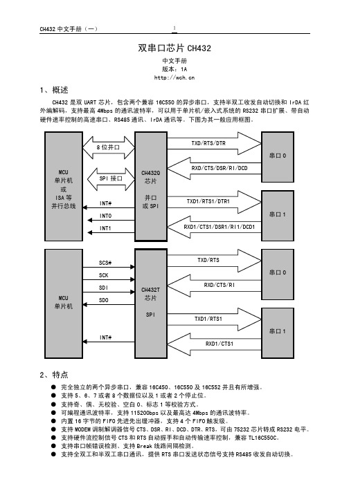
如果选择了并行接口,那么 CH432Q 芯片会根据 ALE#引脚的状态选择地址方式:直接地址和复用
地址。当 ALE#引脚为低电平时选择复用地址方式,否则选择直接地址方式。在直接地址方式下,地
址是从 A3~A0 引脚直接输入;在复用地址方式下,地址是由 ALE 引脚控制从 D3~D0 引脚输入锁存。
引脚状态
半双工通讯方式。这种半双工通讯又可以分为两种具体应用:半双工串口(包括但不限于 RS485 通讯
应用)、IrDA 红外串口 SIR。在半双工串口应用中,RTS 引脚(串口 1 则是 RTS1 引脚)用于串行数据
正在发送状态指示,高电平有效,可以用于自动控制 RS485 收发器的收发切换。在红外串口 SIR 应用
位6
SLP/CK2X 寄存器位之外,串口 0 与串口 1 的寄存器都相同。表中 DLAB 为寄存器 LCR 的位 7,X 表示
不关心 DLAB 值,RO 表示寄存器只读,WO 表示寄存器只写,R/W 表示寄存器可读可写。
地 址
DLAB R/W
名 称
位7
位6
位5
位4
位3
位2
位1
位0
0 0 RO RBR 位 7
串口波特率,那么应该设置 CK2X 为 1,并且选择较高的外部时钟频率。如果需要产生特殊数值的串
口波特率,那么应该选择特定频率的外部时钟或者晶体。
下表是根据 CK2X 值和外部晶体频率产生串口的内部时钟频率和最大串口波特率。
外部输入时钟频率
CK2X=0,内部 1/12 分频
CK2X=1,内部 2 倍频
串口 0 为全双工通讯
串口 0 为红外串口 SIR
CTS 引脚接地或者接低电平
CRS485
- 1、下载文档前请自行甄别文档内容的完整性,平台不提供额外的编辑、内容补充、找答案等附加服务。
- 2、"仅部分预览"的文档,不可在线预览部分如存在完整性等问题,可反馈申请退款(可完整预览的文档不适用该条件!)。
- 3、如文档侵犯您的权益,请联系客服反馈,我们会尽快为您处理(人工客服工作时间:9:00-18:30)。
EVERLIGHT ELECTRONICS CO.,LTD.
Device Number :DDS-432-001REV: 1.3 0.39" Single Digit Displays
MODEL NO :ELS-432SRWA ECN :Page:1/5█ Features :█ Applications:
●Industrial standard size. ●Audio equipment
●Low power consumption. ●Instrument panels
●Categorized for luminous intensity.●Digital read out display
█ Descriptions :
●The ELS-432 series is a large 10.0mm
(0.39")high seven segment display
design for viewing distances up to
7 meters.
●These displays provide excellent
reliability in bright ambient light .
●These device is made with white
segments and gray surface.
PART NO CHIP C.C. or C.A.
Material Emitted Color
ELS-432SRWA GaAlAs Super Red C.A.
OFFICE : NO. 25,Lane 76,Sec.3, Chung Yang Rd., Tucheng 236, Taipei, Taiwan, R.O.C.
TEL : 886-2-2267-2000,2267-9936
FAX : 886-2-2267-6244,22676189,22676306
EVERLIGHT ELECTRONICS CO.,LTD.
Device Number :DDS-432-001REV: 1.3 0.39" Single Digit Displays
MODEL NO :ELS-432SRWA ECN :Page:2/5
█ NOTES:
1.All dimensions are in millimeters ,tolerance is 0.25mm unless otherwise noted.
2.Above specification may be changed without notice.
Supplier will reserve authority on material change for above specification.
EVERLIGHT ELECTRONICS CO.,LTD.
Device Number :DDS-432-001REV: 1.3 0.39" Single Digit Displays
MODEL NO :ELS-432SRWA ECN :Page:3/5
█Absolute maximum ratings at Ta = 25℃:
Parameter Symbol Rating Unit
Reverse Voltage Vr5V
Forward Current If40mA
Operating Temperature Topr-40 to +85℃
Storage Temperature Tstg-40 to +100℃
Soldering Temperature Tsol260 ± 5℃
Power Dissipation Pd110mW
Peak Forward Current(Duty
1/10 @ 1KHZ)
If(Peak)180mA
█Electronic optical characteristics :
Parameter Symbol MIN.TYP.MAX.Unit Condition
Luminous
Per
segment
Iv 2.80 4.0----
mcd If=10mA
Intensity Per
decimal point 0.75 2.00----
mcd If=10mA
Peak Wavelengthλp----660----nm If=20mA Dominant Wavelengthλd----643----nm If=20mA Spectrum Rediation
Bandwidth△λ
----20----nm If=20mA Forward Voltage Vf 1.5 1.7 2.4V If=20mA Reverse Current Ir--------10µA Vr=5V
EVERLIGHT ELECTRONICS CO.,LTD.
Device Number :DDS-432-001REV: 1.3 0.39" Single Digit Displays
MODEL NO :ELS-432SRWA ECN :Page:4/5█ Reliability test item and condition:
NO Item Test Conditions
Test
Hours/Cycle
Sample Size Ac/Re
1Solder Heat TEMP : 260℃ ± 5 ℃ 5 SEC76 PCS0/1
H : +85℃ 30min
2Temperature Cycle∫ 5 min50 CYCLE76 PCS0/1
L : -55℃ 30min
H : +100℃ 5min
3Thermal Shock∫ 10 sec50 CYCLE76 PCS0/1
L : -10℃ 5min
4High Temperature
Storage
TEMP : 100℃1000 HRS76 PCS0/1
5Low Temperature
Storage
TEMP : -55℃1000 HRS76 PCS0/1
6DC Operating Life If = 10 mA1000 HRS76 PCS0/1
7High Temperature / High
Humidity
85℃/85% RH1000 HRS76 PCS0/1
EVERLIGHT ELECTRONICS CO.,LTD.
Device Number :DDS-432-001REV: 1.3 0.39" Single Digit Displays
MODEL NO:ELS-432SRWA ECN :Page:5/5。