spi_tolerance_rigid_PVC
1X9光模块接口规范%20v1.4(2010-8-9)
图 3. CML 输出结构
图 4. CML 在不同负载时的输出波形
5
---------------------------------------------------------------------------------------------------------------------------------------------------------------
Vcc-1.16
Vcc-0.88
V
输入低电平
Vcc-1.81
Vcc-1.48
V
在+5.0V 和+3.3V 供电系统中,PECL 接口均适用,+3.3V 供电系统中的 PECL 常被称作低压 PECL,简
写为 LVPECL。
在使用 PECL 电路时要注意加电源去耦电路,以免受噪声的干扰,同时输出采用交流还是直流耦合对负载网
武汉启晟科技有限公司
网址: TEL:86-27-87808373 87745141 FAX:87745140
地址:武汉市东湖开发区光谷大道特一号国际企业中三期锦丰楼 B 座 304 邮编:430074
武汉启晟科技有限公司
1×9 光模块接口规范
版本:1.4(复稿)
武汉启晟科技有限公司
网址: TEL:86-27-87808373 87745141 FAX:87745140
地址:武汉市东湖开发区光谷大道特一号国际企业中三期锦丰楼 B 座 304 邮编:430074
武汉启晟科技有限公司
1×9 光模块接口规范
版本记录
序号 版本编号 版本发布时间
武汉启晟科技有限公司
网址: TEL:86-27-87808373 87745141 FAX:87745140
爱普生晶振EG-2121CB差分晶体振荡器规格书
关于在目录内使用的记号
●无铅。 ●符合欧盟 RoHS 指令。 欧盟 RoHS 指令免检的含铅产品。 (密封玻璃、高温熔化性焊料或其他材料中包含铅。 ) ●为汽车方面的应用,如汽车多媒体、车身电子、遥控无钥门锁等。
●为汽车行驶安全方面的应用(引擎控制单元、气囊、电子稳定程序控制系统) 。
注意事项
·本材料如有变更,恕不另行通知。量产设计时请确认最新信息。 ·未经 Seiko Epson 公司书面授权,禁止以任何形式或任何方式复制或者发布本材料中任何部分的信息内容。 ·本材料中的书面信息、应用电路、编程、使用等内容仅供参考。Seiko Epson 公司对第三方专利或版权的侵权行为不负有任何责任。本材料 未对任何专利或知识版权的许可权进行授权。 ·本材料中规格表中的数值大小通过数值线上的大小关系表示。 ·当出口此材料中描述的产品或技术时,你应该遵守相应的出口管制法律和法规,并按照这些法律和法规的要求执行。 请不要将产品(以及任何情况下提供任何的技术信息)用于开发或制造大规模杀伤性武器或其他军事用途。还要求,不要将产品提供给任何 将产品用于此类违禁用途的第三方。 ·此类产品是基于在一般电子机械内使用而设计开发的,如将产品应用于需要极高可靠性的特定用途,必须实现得到弊公司的事前许可。若 无许可弊公司将不负任何责任。 1.太空设备(人造卫星、火箭等) 2.运输车辆机器控制装置(汽车、飞机、火车、船舶等) 3.用于维持生命的医疗器械 4.海底中转设备 5.发电站控制机器 6.防灾防盗装置 7.交通设备 8.其他,用于与 1~7 具有同等可靠性的用途。
本材料中记载的品牌名称或产品名称是其所有人的商标或注册商标。
Seiko Epson Corporation
【EPSON晶振大中华区样品中心 - 深圳扬兴科技有限公司】
c2quick

Quick Reference GuideCAESAR II™•V E R S I O N 4.50( L A S T R E V I S E D 9/2003)CAESAR II Quick Reference Guide (Version 4.40)The CAESAR II Quick Reference Guide is intended to aid users in quickly identifying n eeded in formation an d to resolve common question s an d problems. This Referen ce Guide is distributed with each copy of the software and users are urged to copy the Reference Guide as necessary.Commen ts an d suggestion s con cern in g CAESAR II, the User Guide, or the Quick Reference Guide are always welcome. Users with problems, questions, or suggestions can contact the COADE Development/Support staff at:techsupprt@ CAESAR IICAESAR II is an advan ced PC based tool for the en gin eer who design s or an alyzes pipin g systems. CAESAR II uses in put spreadsheets, on-lin e help, graphics, an d exten sive errordetection procedures to facilitate timely operationand solution.CAESAR II is capable of analyzing large piping models, structural steel models, or combined models, both statically and dynamically. ASME, B31, WRC, and rotating equipment reports combine to provide the analyst with a complete description of the piping system’s behavior under the applied loading conditions. Additional technical capabilities such as out-of-core solvers, force spectrum analysis (for water hammer and relief valve solutions), time history, and large rotation rod hangers provide the pipe stress engineer with the most advanced computer based piping program available today. CAESAR II is continuously enhanced to incorporate new technical abilities, to provide additional functionality, and to modify existing computation procedures as the piping codes are updated. A complete list of the most recent changes to CAESAR II can be found in Chapter 1 of the User Guide. Users desiring software sales are urged to contact the COADE Sales staff at:Phone:281-890-4566E-mail:sales@FAX:281-890-3301Web:CAESAR II / Pipe Stress SeminarsCOADE offers seminars periodically to augment the Engineers knowl edge ofCAESAR II and Pipe Stress Analysis . The general seminar is held in our Houston office and covers five days of statics and three days of dynamics. This seminar emphasizes the piping codes, static analysis, dynamic analysis, and problem solving.Custom semin ars held at clien t location s are also available. For addition al semin ar details, please contact COADE at seminars@.CAESAR II Quick Reference GuideTable of ContentsSystem Requirements (1)Troubleshooting (1)Overview of CAESAR II Interfaces (3)List of CAESAR II Piping Codes (3)Restraints (4)List of Setup File Directives (4)List of Materials (7)Intersection Types in CAESAR II (8)Code Stresses (9)Node Locations on Bends (17)CAESAR II Combined Index (19)CAESAR II Quality Assurance Manual (50)Mechan ical En gin eerin g News (50)Additional COADE Software Programs (50)System RequirementsMinimum Average PreferredPentium 500 Mhz Dual Pentium 700 Mhz Pentium 2 Ghzor Pentium 1 Ghz128 Mbytes of RAM256 Mbytes of RAM512 Mbytes of RAMWindows 98 or later *Windows 98 or later *Windows 2000 or XP100 Mbytes of Hard Disk Space 2 Gbytes of Hard Disk Space 2 Gbytes of Hard Disk Space8 Mbytes of Video RAM64 Mbytes of Video RAM128 Mbytes of Video RAM800 x 600 Video Resolution1024 x 768 Video Resolution1280x1024 Video ResolutionTroubleshootingFor troubleshooting and problem solving issues, please refer to the CAESAR II FAQ located on our website. The direct lin k to the documen t is / c2articles/c2_faq_web.html.Overview of CAESAR II InterfacesThere are several extern al in terfaces in existen ce which tran sfer data between CAESAR II and other software packages. These interfaces can be accessed via the TOOLS option of the main menu.CADWorx(requies AutoCAD)AUTOCAD(DXF Output)COMPUTER VISION(main frame)INTERGRAPH(mainframe)CADPIPE(requires AutoCAD)ISOMET(mainframe)PDMS(mainframe)PCF(Alias format)Users interested in these interfaces should contact COADE for further information. We anticipate other interfaces in the future. We will keep users updated via the newsletter or revised documentation.List of CAESAR II Piping CodesPIPING CODE PUBLICATION REVISION ANSI B31.1(2001)Decem ber 10, 2001ANSI B31.3(1999)April 30, 2002ANSI B31.4(1998)October 4, 2002ANSI B31.4 Chapter IX(1998)October 4, 2002ANSI B31.5(2001)November 1, 2001ANSI B31.8(1999)November 16, 2001ANSI B31.8 Chapter VIII(1999)November 16, 2001ANSI B31.11(1989)June 28, 1991ASME SECT III CLASS 2(2001)July 1, 2003ASME SECT III CLASS 3(2001)July 1, 2003U.S. NAVY 505(1984)N/ACANADIAN Z662(9/95)N/ABS 8061993, ISSUE 1, SEPTEMBER 1993N/ASWEDISH METHOD 12ND EDITION STOCKHOLM 1979N/ASWEDISH METHOD 22ND EDITION STOCKHOLM 1979N/AANSI B31.1(1967)N/ASTOOMWEZEN(1989)N/ARCC-M C(1988)N/ARCC-M D(1988)N/ACODETI(1995)N/ANORWEGIAN(1990, Rev 1)N/AFDBR(1995)N/ABS7159(1989)N/AUKOOA(1994)N/AIGE/TD/12(2003)N/ADNV(1996)N/ARestra intsRestraint Type Abbreviation 1-Anchor...........................................................................................A2-Translational Double Acting.............................................X, Y, or Z3-Rotational Double Acting.........................................RX, RY, or RZ4-Guide, Double Acting................................................................GUI5-Double Acting Limit Stop (I)6-Translational Double Acting Snubber.............XSNB,YSNB, ZSNB7-Translational Directional.............................+X, -X, +Y, -Y, +Z, -Z8-Rotational Directional.....................................+RX, -RX, +RY, etc.9-Directional Limit Stop.................................................+LIM, -LIM10-Large Rotation Rod.....................................XROD, YROD, ZROD11-Translational Double Acting Bilinear.............................X2, Y2, Z212-Rotational Double Acting Bilinear..........................RX2, RY2, RZ213-Translational Directional Bilinear......................-X2, +X2, -Y2, etc.14-Rotational Directional Bilinear.................+RX2, -RX2, +RY2, etc.15-Bottom Out Spring..........................................XSPR, YSPR, ZSPR16-Directional Snubber.........................+XSNB, -XSNB, +YSNB, etc.List of Setup File DirectivesThe following list represents the possible directives which can be controlled by the user via the CAESAR II configuration file CAESAR.CFG. These directives can be changed by the user through the use of the CONFIGURE-SETUP program, accessed via MAIN MENU option #9. Directives are listed in groups corresponding to the configuration program's menu options.GEOMETRY DIRECTIVESCONNECT GEOMETRY THRU CNODES =YES34MIN ALLOWED BEND ANGLE =.5000000E+0136MAX ALLOWED BEND ANGLE =.9500000E+0237BEND LENGTH ATTACHMENT PERCENT =.1000000E+0138MIN ANGLE TO ADJACENT BEND PT =.5000000E+0139LOOP CLOSURE TOLERANCE =.1000000E+0142THERMAL BOWING HORZONTAL TOLERANCE =.1000000E-0392AUTO NODE NUMBER INCREMENT=.1000000E+02109Z AXIS UP N O129 COMPUTATION CONTROLUSE PRESSURE STIFFENING =DEFAULT65ALPHA TOLERANCE =.5000000E-0133HANGER DEFAULT RESTRAINT STIFFNESS =.1000000E+1349 DECOMPOSITION SINGULARITY TOLERANCE =.1000000E+1150BEND AXIAL SHAPE =YES51FRICTION STIFFNESS =.1000000E+0745FRICTION NORMAL FORCE VARIATION =.1500000E+0047FRICTION ANGLE VARIATION =.1500000E+0248FRICTION SLIDE MULTIPLIER =.1000000E+0146ROD TOLERANCE =.1000000E+0159COMPUTATION CONTROL (Cont.)ROD INCREMENT =.2000000E+0158 INCORE NUMERICAL CHECK =N O60 DEFAULT TRANSLATIONAL RESTRAINT STIFFNESS=.1000000E+1398 DEFAULT ROTATIONAL RESTRAINT STIFFNESS=.1000000E+1399 IGNORE SPRING HANGER STIFFNESS =N O100 MISSING MASS ZPA =EXTRACTED101 MINIMUM WALL MILL TOLERANCE=.1200000E+02107 WRC-107 VERSION =MAR 79 1B1/2B1119 WRC-107 INTERPOLATION =LAST VALUE120 AMBIENT TEMPERATURE =70.00135 BORDER PRESSURE =NONE136 COEFFICIENT OF FRICTION =0.140 INCLUDE SPRING STIFFNESS INFREE THERMAL CASES =N O141SIFS AND STRESSESREDUCED INTERSECTION =B31.1(POST1980)32 USE WRC329 =N O62 NO REDUCED SIF FOR RFT AND WLT N O53 B31.1 REDUCED Z FIX =YES54CLASS 1 BRANCH FLEXIBILITY N O55 ALL STRESS CASES CORRODED =N O35 ADD TORSION IN SL STRESS =DEFAULT66 ADD F/A IN STRESS =DEFAULT67 OCCASIONAL LOAD FACTOR =.0000000E+0041 DEFAULT CODE =B31.343 B31.3 SUSTAINED CASE SIF FACTOR =.1000000E+0140 ALLOW USERS BEND SIF =N O52 USE SCHNEIDER =N O63 YIELD CRITERION STRESS =MAX 3D SHEAR108 USE PD/4T =N O64 BASE HOOP STRESS ON =N O57 APPLY_B318_NOTE2 =N O133 DISABLE_UNDO =N O128 LIBERAL ALLOWABLE =YES137 STREE STIFFENING DUE TO PRESS =N O138 B31.3 WELDING/CONTOUR TEE MEET B16.9 =N O139 PRESSURE VARIATION IN EXPANSION CASE DEFAULT143FRP PROPERTIESUSE FRP SIF =YES110USE FRP FLEXIBILITY =YES111BS 7159 Pressure Stiffening=Design Strain121 FRP Property Data File=CAESAR.FRP122 Axial Modulus of Elasticity =.3200000E+07113 Ratio Shear Mod : Axial Mod =.2500000E+00114 Axial Strain : Hoop Stress =.1527272E+00115 FRP Laminate Type =THREE116 FRP Alpha =.1200000E+02117 FRP Density =.6000000E-01118 Exclude f2 from Bending Stress (UKOOA)N O134PLOT COLORSPIPES LIGHTCYAN1 HIGHLIGHTS GREEN2 LABELS GREEN3 BACKGROUND BLACK5 AXES LIGHTRED15 HANGER/NOZZLES BROWN16 RIGID/BENDS LIGHTGREEN17PLOT COLORS (Cont.)NODES YELLOW18 STRUCTURE LIGHTRED31 DISPLACEDSHAPE BROWN30 STRESS > LEVEL 5RED24 STRESS > LEVEL 4YELLOW25 STRESS > LEVEL 3GREEN26 STRESS > LEVEL 2LIGHTCYAN27 STRESS > LEVEL 1BLUE28 STRESS < LEVEL 1DARK BLUE29 STRESS LEVEL 5.3000000E+0519 STRESS LEVEL 4.2500000E+0520 STRESS LEVEL 3.2000000E+0521 STRESS LEVEL 2.1500000E+0522 STRESS LEVEL 1.1000000E+0523DATA BASE DEFINITIONSSTRCT DBASE=AISC89.BIN70 VALVE & FLANGE=CADWORX.VHD90 EXPANSION JT DBASE=PATHWAY.JHD91 PIPING SIZE SPECIFICATION ANSI88DEFAULT SPRING HANGER TABLE =1112 SYSTEM DIRECTORY NAME SYSTEM123 UNITS FILE NAME=ENGLISH.FIL124MISCELLANEOUS CONTROLOUTPUT REPORTS BY LOAD CASE YES87 DISPLACEMENT NODAL SORTING YES89 DYNAMIC INPUT EXAMPLE TEXT MAX94 TIME HIST ANIMATE YES104 OUTPUT TABLE OF CONTENTS O N105 INPUT FUNCTION KEYS DISPLAYED YES106 MEMORY ALLOCATED12N A USER ID" "N A ENABLE ODBC OUTPUT N O125 APPEND RE-RUNS TO EXISTING DATA N O126 ODBC DATABASE NAME<NONE>127<BELOW>ENABLE_AUTOSAVE YES130 AUTOSAVE_TIME_INTERVAL30.131 PROMPTED_AUTOSAVE YES132 LOADCASE TEMPLATE LOAD.TPL142List of MaterialsThe CAESAR II material table contains 17 different isotropic materials. Properties and allowed temperature ranges for each isotropic material are listed below:MATERIAL ELASTIC POISSON’S PIPE TEMPERATURENO. NAME MODULUS RATIO DENSITY RANGE______________________(psi)______________(lb./cu.in)___(deg.F) __1Low Carbon Steel 29.5 E60.2920.28993-32514002High Carbon Steel 29.3 E60.2890.28009-32514003Carbon Moly Steel 29.2 E60.2890.28935-32514004Low Chrome Moly Stl 29.7 E60.2890.28935-32514005Med Chrome Moly Stl 30.9 E60.2890.28935-32514006Austenitic Stainless 28.3 E60.2920.28930-32515007Straight Chromium 29.2 E60.3050.28010-32514008Type 310 Stainless 28.3 E60.3050.28990-32514009Wrought Iron 29.5 E60.3000.28070-325100010Grey Cast Iron 13.4 E60.2110.25580 70100011Monel 67%Ni/30%Cu 26.0 E60.3150.31870-325140012K-Monel 26.0 E60.3150.30610-325140013Copper-Nickel 22.0 E60.3300.33850-325 40014Aluminum 10.2 E60.3300.10130-325 60015Copper 99.8% Cu 16.0 E60.3550.32290 70 40016Commercial Brass 17.0 E60.3310.30610-325120017Leaded Tin Bronze 114.0 E60.3300.31890-3251200In addition CAESAR II supports material types 18 or 19 for cut short and cut long cold spring elements.Material n umber 20 activates the CAESAR II orthotropic material model (i.e. Fiberglass rei nforced plastic pipe); the default coefficie n t of expa n sio nis 12.0 E-6in./in./°F.Material 21 indicates “user defined” properties.Material n umbers over 100 are from the Material Database an d in clude the allowable stress and other piping code data.CAESAR II TYPEB31.3 TYPENOTESSKETCH1 ReinforcedReinforced - Used to lower SIFs - Not a fitting - Modified Pipe2 UnreinforcedUnreinforced - Routine Intersection - Not a fitting - Modified pipe- Usually the cheapest3 Welded Tee Welding Tee- Usually size-on-size - Governed by B16.9- Usually the lowest SIF - Usually Expensive4 SweepoletWelded-in contour - "Sit-in" fitting- Forged fitting on a pipe5 WeldoletBranch Welded On - "Sit-on" fitting- Forged fitting on a pipe6 ExtrudedExtruded Welding Tee- Seldom used- Used for thick wall manifolds - Extruded from straight pipeFabricated TeeFabricated TeeIn sertFittin gIntersection Types in CAESAR IICode StressesListed below are the “code stress” equations for the actual and allowable stresses used by CAESAR II . For the listed codes, the actual stress is defined by the left hand side of the equation an d the allowable stress is defin ed by the right han d side. The CAESAR II load case label is also listed after the equation.Typically the load case recommendations made by CAESAR II are sufficient for code compliance. However, CAESAR II does not recommend occasional load cases. Occa-sional loads are unknown in origin and must be specified by the user.Longitudinal Pressure Stress - SlpSlp = PD 0/4t ncode approximationSlp = PD i 2/(D 02 - D i 2)code exact equation, CAESAR II defaultOperating Stress - unless otherwise specifiedS = Slp + Fax/A + Sb <NA(OPE)B31.1Sl = Slp + 0.75 i Ma / Z <Sh(SUS)i Mc / Z< f [ 1.25 (Sc+Sh) - Sl ](EXP)Slp + 0.75 i Ma / Z + 0.75 i Mb / Z <k Sh(OCC)B31.3S = Slp + Fax/A + sqrt (Sb**2 + 4 St**2)(ope)Sl = Slp + Fax/A + Sb <Sh(SUS)sqrt (Sb**2 + 4 St**2)< f [ 1.25 (Sc+Sh) - Sl ](EXP)Fax/A + Sb + Slp<k Sh(OCC)Sb = [sqrt ( (i i M i )2 + (i 0M 0)2 )]/Z ASME SECT III CLASS 2 & 3B1 * Pmax Do + B2 * Ma / Z < 1.5 Sh(SUS)2tn i Mc / Z< f (1.25 Sc + 0.25 Sh) + Sh - Sl(EXP)B1 * Slpmax + B2 * (Ma + Mb) / Z < 1.8 Sh and < 1.5 Sy.(OCC)B31.1 (1967) and Navy Section 505Sl = Slp + sqrt (Sb**2 + 4 St**2)<Sh(SUS)sqrt ( Sb**2 + 4 St**2 )< f (1.25Sc + 0.25Sh + (Sh-Sl))(EXP)Slp + sqrt (Sb**2 + 4 St**2)<k Sh(OCC)B31.4If FAC = 1.0 (fully restrained pipe)FAC | E α dT - υ S HOOP | + S HOOP<0.9 (Syield)(OPE)If FAC = 0.001 (buried, but soil restraints modeled)Fax/A - ν S HOOP + Sb + S HOOP <0.9 (Syield)(OPE)(If Slp + Fax/A is compressive)If FAC = 0.0 (fully above ground)Slp + Fax/A + Sb + S HOOP<0.9 (Syield)(OPE)(If Slp + Fax/A is compressive)(Slp + Sb + Fax/A) (1.0 - FAC)<(0.75) (0.72) (Syield)(SUS)sqrt ( Sb**2 + 4 St**2 )<0.72 (Syield)(EXP)(Slp + Sb + Fax/A) (1.0 - FAC)<0.8 (Syield)(OCC)B31.4 Chapter IXHoop Stress: S h <= F 1 S y(OPE, SUS, OCC)Longitudinal Stress: |S L | <= 0.8 S y (OPE, SUS, OCC)Equivalent Stress: S e <= 0.9 S y(OPE, SUS, OCC)Where:S y =specified minimum yield strengthF 1=hoop stress design factor (0.60 or 0.72, see Table A402.3.5(a) of the B31.4Code)S h =(P i – P e ) D / 2tS L =S a + S b or S a - S b , whichever results in greater stress value S e =2[((S L - S h )/2)2 + S t 2]1/2B31.5Sl = Slp + Fax/A + Sb <Sh(SUS)sqrt (Sb**2 + 4 St**2)< f [ 1.25 (Sc+Sh) - Sl ](EXP)Fax/A + Sb + Slp<k Sh(OCC)Sb = [sqrt ( (i i M i )2 + (i 0M 0)2 )]/Z B31.8Se + Sl <Syield (OPE)Sl = Slp + Sb<.75 (Syield)(SUS)Se = sqrt ( Sb**2 + 4 St**2)<0.72 (Syield)(EXP)B31.8 Chapter VIIIHoop Stress: S h <= F 1 S T (OPE, SUS, OCC)Longitudinal Stress: |S L | <= 0.8 S (OPE, SUS, OCC)Equivalent Stress: S e <= 0.9 S (OPE, SUS, OCC)Where:S =specified minimum yield strengthF 1=hoop stress design factor (0.50 or 0.72, see Table A842.22 of the B31.8 Code)T =temperature deratin g factor (see Table 841.116A of the B31.8 Code)Note: the product of S and T (i.e., the yield stress at operating temperature) is required in the SH field of the CAESAR II input S h =(P i – P e ) D / 2tS L =maximum longitudinal stress (positive tensile, negative compressive)S e =2[((S L - S h )/2)2 + S s 2]1/2S s =tangential shear stress B31.11If FAC = 1.0 (fully restrained pipe)FAC | E α dT - υ S HOOP | + S HOOP<0.9 (Syield)(OPE)If FAC = 0.001 (buried, but soil restraints modeled)Fax/A - ν S HOOP + Sb + S HOOP <0.9 (Syield)(OPE)(If Slp + Fax/A is compressive)B31.11 (Continued)If FAC = 0.0 (fully above ground)Slp + Fax/A + Sb + S HOOP<0.9 (Syield)(OPE)(If Slp + Fax/A is compressive)(Slp + Sb + Fax/A) (1.0 - FAC)<(0.75) (0.72) (Syield)(SUS)sqrt ( Sb**2 + 4 St**2 )<0.72 (Syield)(EXP)(Slp + Sb + Fax/A) (1.0 - FAC)<0.88 (Syield)(OCC)Canadian Z662If FAC = 1.0 (Fully Restrained Pipe)|E α dT - υ S h | + S h <0.9 S * T(OPE)If FAC = 0.001 (Burried, But Soil Restraints Modeled)|F ax / A - υ S h | + S b + S h<S * T(OPE)(If F ax / A - υ S h is compressive)If FAC = 0.0 (Fully Above Ground)|S lp + F ax / A| + S b + S h<S * T(OPE)(If S lp + F ax / A is compressive)S l = 0.5S h + S b<S * F * L * T (SUS, OCC)S E = sqrt [S b ** 2 + 4S t ** 2]<0.72 S * T(EXP)RCC-M C & DSlp + 0.75i Ma/Z <Sh(SUS)iMc/Z< f (1.25 Sc + .25 Sh) + Sh - Sl (EXP)Slpmax + 0.75i (Ma + Mb)/Z < 1.2 Sh(OCC)StoomwezenSlp + 0.75i Ma/Z <f (SUS)iMc/Z<fe (EXP)Slp + 0.75i (Ma + Mb)/Z< 1.2f(OCC)CODETISl = Slp + Fax/A + Sb <Sh(SUS)sqrt (Sb **2 + 4St **2)< f [1.25 (Sl + Sh)] - Sl (EXP)Slp + Fax/A + iMa/Z + iMb/Z <Ksh(OCC)Sb = [ Sqrt ((i i M i )2 + (i 0M 0)2] /Z NorwegianSl = PDi 2 / Eff(D 02-D i 2) + .75 i Ma/Z < Sh (SUS)iMc/Z<Sh + Sr - Sl(EXP)PmaxDi 2 /Eff(D 02-D i 2) + .75i (Ma + Mb)/Z < 1.2 Sh (OCC)M =sqrt (M x 2 + M y 2 + M z 2)Sr=Minimum of 1.25 Sc + 0.25 Sh; F r R s -F 2; or F r (1.25R 1 + 0.25R 2)(The latter applies to temperatures over 370°c; 425°c for Austenitic stainless steel)F r =Cyclic reduction factorR s =Permissable extent of stress for 7000 cycles R 1=Minimum of Sc and 0.267 R m R 2=Minimum of Sh and 0.367 R mR m=Ultimate tensile strength at room temperatureFDBRSl = Slp + 0.75 i Ma / Z <Sh(SUS)i Mc / Z< f [ 1.25 (Sc+Sh) - Sl ](EXP)Slp + 0.75 i Ma / Z + 0.75 i Mb / Z <k Sh(OCC)BS 7159If S x is tensile:()sqrt S 4S x 2s2+<Sh (OPE)and()sqrt S 4S 2s2φ+<Sh*E H /E A (OPE)or, if S x is compressive:S S x xφνφ−<Sh*E H /E A(OPE)BS 7159 (Continued)an dS x< 1.25Sh(OPE)()()()()()S P D t sqrt i M i M Zx m xi i xo o =++422()()()()()P D t sqrt i M i M Z F Am xi i xo o x 422−+−(If F x /A > P(D m )/(4t), and it is compressive)()S MP D t m φ=()2(for straight pipes) ()()()=++MP D t sqrt i M iM Zm i i o o()222φφ(for bends)()()()()=++MP D t sqrt i M i M Zm xi i xo o ()222(for tees),D and are always for the Run Pipem t Eff = Ratio of E φ to E xUKOOAσa b (f 2/r) + PD m / (4t) ≤ (f 1 f 2 LTHS) / 2.0Where:P =design pressure D m =pipe mean diameter t =pipe wall thicknessf 1=factor of safety for 97.5% lower confidence limit, usually 0.85f 2=system factory of safety, usually 0.67σa b =axial bending stress due to mechanical loads r =σa(0:1) /σa(2:1)σa(0:1)=long term axial tensile strength in absence of pressure load σa(2:1)=long term axial tensile strength in under only pressure loading LTHS=long term hydrostatic strength (hoop stress allowable)BS 806Straight Pipe <S A OPE f c =sqrt(F 2+ 4f s 2)<S A SUS <S A EXPf s =M t (d + 2t) / 4I F =max (f t , f L )f t=pd/2t + 0.5pf L =pd 2/[4t(d + t)] + (d + 2t)[sqrt(m i 2 + m o 2)] / 2I Bends<S A OPE f c =sqrt (F 2+ 4 f s2)<S A SUS <S A EXPf s =M t (d + 2t) /4I F =max (f t , f L )f t=r/I * sqrt[(m i F Ti )2 + (m 0F To )2]f s =r/I * sqrt[(m i F Li )2 + (m 0F Lo )2]Branch Junctions <S A OPE f cb =q * sqrt[f b2 + 4f sb 2]<S A SUS <S A EXPf b =(d + t)*p*m/(2t) + r/I*sqrt[(m i F TL )2 + (m o F TO )2]F sb =Mt (d + 2t) / 4I q=1.0 except for operating cases=.5 or .44 bases on d 2/d 1 ratio in operating cases m =geometric parameterEXP S A =min[(H*S proof ambient + H*S proof design ), (H*S proof ambient + F)]OPE S A =S avg rupture at design temperature SUS S A =min[.8*S proof , S creep rupture ]Det Norske Veritas (DNV)Hoop Stress: Sh <= nsSMYS(OPE, SUS, OCC)Hoop Stress: Sh <= nuSMTS(OPE, SUS, OCC)Longitudinal Stress: SL<= n SMYS(OPE, SUS, OCC)Equivalent Stress: Se<= n SMYS(OPE, SUS, OCC) Where:S h =(Pi– Pe) (D – t) / 2tn s =hoop stress yielding usage factor (see Tables C1 and C2 of the DNV Code)SMYS=specified minimum yield strength, at operating temperaturen u =hoop stress bursting usage factor (see Tables C1 and C2 of the DNV Code)SMTS=specified minimum tensile strength, at operating temperatureS L =maximum lon gitudin al stressn=equivalent stress usage factor (see Table C4 of the DNV Code)S e =[Sh2 + SL2 - ShSL+ 3t2]1/2Node Locations on Bends•Bends are defined by the element entering the bend and the element leaving the bend. The actual ben d curvature is always physically at the “TO” en d of the elemen t en terin g the ben d.•The element leaving a bend must appear immediately after the element defining (entering) the bend.•The default bend radius is 1.5 times the pipe nominal OD.•For stress and displacement output the “TO” node of the element entering the bend is located geometrically at the “FAR” point on the bend. The “FAR” point is at the weldline of the bend, and adjacent to the straight element leaving the bend.•The “NEAR” point on the bend is at the weldline of the bend, and adjacent to the straight element entering the bend.•The “FROM” point on the element is located at the “NEAR” point of the bend if the total length of the element as specified in the DX, DY and DZ fields is equal to: Radius * tan( Beta / 2 ) where “Beta” is the bend angle, and “Radius” is the bend radius of curvature to the bend centerline.•Nodes defin ed in the ANGLE # an d NODE # fields are placed at the given an gle on the ben d curvature. The angle starts with zero degrees at the “NEAR” point on the bend and goes to “Beta” degrees at the “FAR” point of the bend.•Angles are always entered in degrees.•By default, nodes on the bend curvature cannot be specified within five (5) degrees of one another or within five degrees of the nearest endpoint. This and other bend settings may be changed through the MAIN MENU, CONFIGURE-SETUP processor. (See pp Q5-6)•When the “FROM” node on the element entering the bend is not at the bend “NEAR” point a node may be placed at the near point of the bend by entering an ANGLE # on the bend spreadsheet equal to 0.0 degrees. (See the following figure.)•When defin in g a ben d elemen t for the first time in the pipe spreadsheet, n odes are automatically placed at the near and mid point of the bend. The generated midpoint node number is one less than the “TO” node number on the element, and the generated near point node number is two less than the “TO” node number on the element. A near point should always be included in the model in tight, highly formed piping systems.The top-left figure below shows the points on the bend as they would be input. The top-right figure shows the actual geometric location of the points on the bend. The bottom-left figure shows the same geometry except that two nodes are defined on the bend curvature at angles of zero and forty-five degrees.•For an animated tutorial on modeling bends, click the "animated Tutorials" option on the "Help" menu.CAESAR II Quality Assurance ManualThe CAESAR II Quality Assurance Manual is intended to serve as a publicly available verification documen t. This man ual discusses (briefly) the curren t in dustry QA stan dards, the COADE QA stan dard, a series of ben chmark jobs, an d in struction s for users implementing QA procedures on their own hardware.The benchmark jobs consists of comparisons to published data by ASME and the NRC.Additional test jobs compare CAESAR II results to other industry software programs.For addition al in formation on the CAESAR II Quality Assuran ce Man ual, please con tact the COADE sales department.Mechanical Engineering NewsAs an aid to the Users of COADE software products, COADE publishes Mechanical Engineering News several times a year. This publication contains discussions on recent developmen ts that affect users, an d techn ical features illustratin g modelin g techn iques an d software application s.This newsletter is sent to all users of COADE software at the time of publication. Back issues can be acquired by contacting the COADE sales staff.Additional COADE Software ProgramsCADWorx-An AutoCAD based piping design/drafting program with a bi-directional data transfer link to CAESAR II. CADWorx allows models to be createdin ortho, iso, 2D, or 3D modes. CADWorx template specification s,combined with built in auto routing, auto iso, stress iso, auto dimensioning,complete libraries, center of gravity calculations, and bill of materials,provides the most complete piping package to designers.CodeCalc-A program for the design or an alysis of pressure vessel compon en ts.CodeCalc capabilities include: tubesheets, rectangular vessels, flanges,nozzles, Zick analysis, and the standard internal/external thickness andpressure computations on heads, shells, and cones.PVElite-A comprehensive, GUI based program for the design or analysis of tall towers and horizontal vessels. Additional modules for nozzles, flanges,baserings, and WRC107 are provided.TANK-A program for the design or rerating of API-650/653 storage tanks. The program includes API-650 Appedices A, E, F, M, P, and S, as well as API-653 Appen dix B. Computation s address: win d girders, con ical roof design,allowed fluid heights, and remaining corrosion allowance.COADE, Inc.12777 Jones Rd., Suite 480Houston, Texas 77070Phone: (281)890-4566Fax: (281)890-3301E-mail: sales@ WWW: C A E S A R I I ™Q U I C K R E F E R E N C E G U I D E V E R S I O N 4.50( L A S T R E V I S E D 9/2003 )•。
AD9255
14-Bit, 125 MSPS/105 MSPS/80 MSPS,1.8 V Analog-to-Digital ConverterAD9255 Rev. AInformation furnished by Analog Devices is believed to be accurate and reliable. However, noresponsibility is assumed by Analog Devices for its use, nor for any infringements of patents or other rights of third parties that may result from its use. Specifications subject to change without notice. No license is granted by implication or otherwise under any patent or patent rights of Analog Devices. T rademarks and registered trademarks are the property of their respective owners. One Technology Way, P.O. Box 9106, Norwood, MA 02062-9106, U.S.A. Tel: 781.329.4700 Fax: 781.461.3113 ©2009–2010 Analog Devices, Inc. All rights reserved.FEATURESSNR = 78.3 dBFS @ 70 MHz and 125 MSPSSFDR = 93 dBc @ 70 MHz and 125 MSPSLow power: 371 mW @ 125 MSPS1.8 V analog supply operation1.8 V CMOS or LVDS output supplyInteger 1-to-8 input clock dividerIF sampling frequencies to 300 MHz−153.4 dBm/Hz small signal input noise with 200 Ω input impedance @ 70 MHz and 125 MSPSOptional on-chip ditherProgrammable internal ADC voltage reference Integrated ADC sample-and-hold inputsFlexible analog input range: 1 V p-p to 2 V p-p Differential analog inputs with 650 MHz bandwidth ADC clock duty cycle stabilizerSerial port controlUser-configurable, built-in self-test (BIST) capability Energy-saving power-down modes APPLICATIONSCommunicationsMultimode digital receivers (3G)GSM, EDGE, W-CDMA, LTE, CDMA2000, WiMAX, andTD-SCDMASmart antenna systemsGeneral-purpose software radiosBroadband data applicationsUltrasound equipmentPRODUCT HIGHLIGHTS1.On-chip dither option for improved SFDR performancewith low power analog input.2.Proprietary differential input that maintains excellent SNRperformance for input frequencies up to 300 MHz.3.Operation from a single 1.8 V supply and a separate digitaloutput driver supply accommodating 1.8 V CMOS orLVDS outputs.4.Standard serial port interface (SPI) that supports variousproduct features and functions, such as data formatting(offset binary, twos complement, or gray coding), enabling the clock DCS, power-down, test modes, and voltagereference mode.5.Pin compatibility with the AD9265, allowing a simplemigration up to 16 bits.FUNCTIONAL BLOCK DIAGRAM1414DRVDD (1.8V) D13 TO D0 OEBDCODITHERCLK+ CLK–SYNCCLOCKMANAGEMENTADC14-BITCOREOUTPUTSTAGINGCMOS ORLVDS(DDR)VCM VREFVIN+ VIN–TRACK-AND-HOLDREFERENCESERIAL PORTSVDD SCLK/DFSSDIO/DCSCSBAD9255OR855-1Figure 1.查询"AD9255"供应商Rev. A | Page 2 of 44TABLE OF CONTENTSFeatures .............................................................................................. 1 Applications ....................................................................................... 1 Product Highlights ........................................................................... 1 Functional Block Diagram .............................................................. 1 Revision History ............................................................................... 2 General Description ......................................................................... 3 Specifications ..................................................................................... 4 ADC DC Specifications ................................................................. 4 ADC AC Specifications ................................................................. 5 Digital Specifications ................................................................... 6 Switching Specifications ................................................................ 8 Timing Specifications .................................................................. 9 Absolute Maximum Ratings .......................................................... 10 Thermal Characteristics ............................................................ 10 ESD Caution ................................................................................ 10 Pin Configurations and Function Descriptions ......................... 11 Typical Performance Characteristics ........................................... 15 Equivalent Circuits ......................................................................... 23 Theory of Operation ...................................................................... 25 ADC Architecture ...................................................................... 25 Analog Input Considerations .................................................... 25 Voltage Reference ....................................................................... 28 Clock Input Considerations ...................................................... 29 Power Dissipation and Standby Mode .................................... 31 Digital Outputs ........................................................................... 32 Timing ......................................................................................... 32 Built-In Self-Test (BIST) and Output Test .................................. 33 Built-In Self-Test (BIST) ............................................................ 33 Output Test Modes ..................................................................... 33 Serial Port Interface (SPI) .............................................................. 34 Configuration Using the SPI ..................................................... 34 Hardware Interface ..................................................................... 34 Configuration Without the SPI ................................................ 35 SPI Accessible Features .............................................................. 35 Memory Map .................................................................................. 36 Reading the Memory Map Register Table ............................... 36 Memory Map Register Table ..................................................... 37 Memory Map Register Descriptions ........................................ 39 Applications Information .............................................................. 40 Design Guidelines ...................................................................... 40 Outline Dimensions ....................................................................... 41 Ordering Guide .. (41)REVISION HISTORY1/10—Rev. 0 to Rev. AChanges to Worst Other (Harmonic or Spur) Parameter,Table 2 ................................................................................................ 6 Changes to Figure 77 ...................................................................... 29 Changes to Input Clock Divider Section ..................................... 30 Changes to Table 17 ........................................................................ 37 Updated Outline Dimensions . (41)10/09—Revision 0: Initial VersionRev. A | Page 3 of 44GENERAL DESCRIPTIONThe AD9255 is a 14-bit, 125 MSPS analog-to-digital converter (ADC). The AD9255 is designed to support communications applications where high performance combined with low cost, small size, and versatility is desired.The ADC core features a multistage, differential pipelined architecture with integrated output error correction logic to provide 14-bit accuracy at 125 MSPS data rates and guarantees no missing codes over the full operating temperature range. The ADC features a wide bandwidth differential sample-and-hold analog input amplifier supporting a variety of user-selectable input ranges. It is suitable for multiplexed systems that switch full-scale voltage levels in successive channels and for sampling single-channel inputs at frequencies well beyond the Nyquist rate. Combined with power and cost savings over previously available ADCs, the AD9255 is suitable for applications in communications, instrumentation, and medical imaging. A differential clock input controls all internal conversion cycles. A duty cycle stabilizer provides the means to compensate for vari-ations in the ADC clock duty cycle, allowing the converters to maintain excellent performance over a wide range of input clock duty cycles. An integrated voltage reference eases design considerations.The ADC output data format is either parallel 1.8 V CMOS or LVDS (DDR). A data output clock is provided to ensure proper latch timing with receiving logic.Programming for setup and control is accomplished using a 3-wire SPI-compatible serial interface. Flexible power-down options allow significant power savings, when desired. An optional on-chip dither function is available to improve SFDR performance with low power analog input signals.The AD9255 is available in a Pb-free, 48-lead LFCSP and is specified over the industrial temperature range of −40°C to +85°C.Rev. A | Page 4 of 44SPECIFICATIONSADC DC SPECIFICATIONSAVDD = 1.8 V , DRVDD = 1.8 V , SVDD = 1.8 V , maximum sample rate, VIN = −1.0 dBFS differential input, 1.0 V internal reference, DCS enabled, unless otherwise noted. Table 1.Parameter Temp AD9255BCPZ-801 AD9255BCPZ-1051 AD9255BCPZ-1251Unit Min Typ Ma x Min Typ Ma x Min Typ Ma x RESOLUTION Full 14 14 14 Bits ACCURACY No Missing Codes Full Guaranteed Guaranteed Guaranteed Offset Error Full ±0.05 ±0.25 ±0.05 ±0.25 ±0.05 ±0.25 % FSRGain Error Full ±0.2 ±2.5 ±0.2 ±2.5 ±0.4 ±2.5 % FSR Differential Nonlinearity (DNL)2 Full ±0.4 ±0.4 ±0.45 LSB 25°C ±0.2 ±0.2 ±0.25 LSB Integral Nonlinearity (INL)2 Full ±0.9 ±0.9 ±1.2 LSB25°C ±0.35 ±0.45 ±0.7 LSB TEMPERATURE DRIFT Offset Error Full ±2 ±2 ±2 ppm/°C Gain Error Full ±15 ±15 ±15 ppm/°C INTERNAL VOLTAGE REFERENCE Output Voltage Error (1 V Mode) Full +8 ±12 +8 ±12 +8 ±12 mV Load Regulation @ 1.0 mA Full 3 3 3 mV INPUT REFERRED NOISE VREF = 1.0 V 25°C 0.62 0.63 0.61 LSB rmsANALOG INPUTInput Span, VREF = 1.0 V Full 22 2 V p-pInput Capacitance 3 Full88 8 pFInput Common-Mode Voltage Full 0.90.9 0.9 VREFERENCE INPUT RESISTANCE Full 66 6 kΩPOWER SUPPLIES Supply Voltage AVDD Full 1.7 1.8 1.9 1.7 1.8 1.9 1.7 1.8 1.9 V DRVDD Full 1.7 1.8 1.9 1.7 1.8 1.9 1.7 1.8 1.9 VSVDD Full1.7 3.5 1.7 3.51.7 3.5VSupply CurrentIAVDD 2 Full 126131169176194 202 mA IDRVDD 2 (1.8 V CMOS) Full1319 23 mA IDRVDD 2 (1.8 V LVDS) Full3942 44 mA POWER CONSUMPTIONDC Input Full239248321332371 382 mW Sine Wave Input 2CMOS Output Mode Full252338 391 mW LVDS Output Mode Full306384 437 mW Standby Power 4 Full5454 54 mW Power-Down Power Full0.050.150.050.150.05 0.15 mW1 The suffix following the part number refers to the model found in the Ordering Guide section.2Measured with a low input frequency, full-scale sine wave, with approximately 5 pF loading on each output bit. 3Input capacitance refers to the effective capacitance between one differential input pin and AGND. 4Standby power is measured with a dc input, the CLK pins (CLK+, CLK−) inactive (set to AVDD or AGND).Rev. A | Page 5 of 44ADC AC SPECIFICATIONSAVDD = 1.8 V , DRVDD = 1.8 V , SVDD = 1.8 V , maximum sample rate, VIN = −1.0 dBFS differential input, 1.0 V internal reference, DCS enabled, unless otherwise noted. Table 2.Parameter 1 Temp AD9255BCPZ-802 AD9255BCPZ-1052 AD9255BCPZ-1252Unit Min Typ Max Min Typ Max Min Typ Max SI G NAL-TO-NOISE-RATIO (SNR) f IN = 2.4 MHz 25°C 79.2 78.9 78.3 dBFS f IN = 70 MHz 25°C 78.9 78.5 78.3 dBFS Full 78.1 77.6 76.9 dBFS f IN = 140 MHz 25°C 78.0 77.7 77.1 dBFS f IN = 200 MHz 25°C 76.9 76.4 75.5 dBFSSIGNAL-TO-NOISE-AND DISTORTION (SINAD)f IN = 2.4 MHz 25°C 78.7 78.6 78.0 dBFS f IN = 70 MHz 25°C 78.7 78.0 78.0 dBFS Full 77.9 77.3 76.7 dBFS f IN = 140 MHz 25°C 76.8 77.0 76.7 dBFSf IN = 200 MHz 25°C 75.8 75.3 74.3 dBFSEFFECTIVE NUMBER OF BITS (ENOB)f IN = 2.4 MHz 25°C 12.812.8 12.7 Bits f IN = 70 MHz 25°C 12.812.7 12.7 Bits f IN = 140 MHz 25°C 12.512.5 12.4 Bits f IN = 200 MHz 25°C 12.312.2 12.0Bits WORST SECOND OR THIRD HARMONIC f IN = 2.4 MHz 25°C −88 −90 −88 dBc f IN = 70 MHz25°C −94 −89 −93 dBc Full −91−88 −85 dBc f IN = 140 MHz 25°C −82 −86 −89 dBc f IN = 200 MHz 25°C −81 −81 −80 dBc SPURIOUS-FREE DYNAMIC RANGE (SFDR) f IN = 2.4 MHz 25°C 88 90 88 dBc f IN = 70 MHz 25°C 94 89 93 dBcFull 91 88 85 dBcf IN = 140 MHz 25°C 82 86 89 dBc f IN = 200 MHz 25°C 81 81 80 dBc SPURIOUS-FREE DYNAMIC RANGE (SFDR) Without Dither (AIN @ −23 dBFS) f IN = 2.4 MHz 25°C 102 99 96 dBFS f IN = 70 MHz 25°C 103 97 99 dBFS f IN = 140 MHz 25°C 104 97 98 dBFS f IN = 200 MHz 25°C 102 101 97 dBFS With On-Chip Dither (AIN @ −23 dBFS) f IN = 2.4 MHz 25°C 110 109 108 dBFS f IN = 70 MHz 25°C 110 108 109 dBFS f IN = 140 MHz 25°C 110 108 109 dBFS f IN = 200 MHz 25°C 110 109 109 dBFSRev. A | Page 6 of 44Parameter 1 Temp AD9255BCPZ-802 AD9255BCPZ-1052 AD9255BCPZ-1252Unit Min Typ Max Min Typ Max Min Typ Max WORST OTHER (HARMONIC OR SPUR) Without Ditherf IN = 2.4 MHz 25°C −106 −105 −101dBc f IN = 70 MHz 25°C −106 −104 −104dBc Full −94−95 −91 dBc f IN = 140 MHz 25°C −104 −104 −103dBc f IN = 200 MHz 25°C −102 −103 −100dBc With On-Chip Ditherf IN = 2.4 MHz 25°C −105 −106 −101dBc f IN = 70 MHz 25°C −106 −105 −104dBc Full −97−99 −98 dBc f IN = 140 MHz 25°C −103 −103 −103dBc f IN = 200 MHz 25°C −100 −101 −100 dBc TWO-TONE SFDRWithout Ditherf IN = 29 MHz (−7 dBFS ), 32 MHz (−7 dBFS ) 25°C 9390 95 dBc f IN = 169 MHz (−7 dBFS ), 172 MHz (−7 dBFS ) 25°C 8078 79 dBc ANALOG INPUT BANDWIDTH25°C650650650 MHz1 See the AN-835 Application Note, Understanding High Speed ADC Testing and Evaluation , for a complete set of definitions.2The suffix following the part number refers to the model found in the section.Ordering GuideDIGITAL SPECIFICATIONSAVDD = 1.8 V , DRVDD = 1.8 V , SVDD = 1.8 V , maximum sample rate, VIN = −1.0 dBFS differential input, 1.0 V internal reference, and DCS enabled, unless otherwise noted. Table 3.Parameter Temperature Min Typ Max Unit DIFFERENTIAL CLOCK INPUTS (CLK+, CLK−) Logic Compliance CMOS/LVDS/LVPECL Internal Common-Mode Bias Full 0.9 V Differential Input Voltage Full 0.3 3.6 V p-p Input Voltage Range Full AGND AVDD V Input Common-Mode Range Full 0.9 1.4 V High Level Input Current Full −100 +100 μA Low Level Input Current Full −100 +100 μA Input Capacitance Full 4 pF Input Resistance Full 8 10 12 kΩ SYNC INPUT Logic Compliance CMOS Internal Bias Full 0.9 V Input Voltage Range Full AGND AVDD V High Level Input Voltage Full 1.2 AVDD V Low Level Input Voltage Full AGND 0.6 V High Level Input Current Full −100 +100 μA Low Level Input Current Full −100 +100 μA Input Capacitance Full 1 pF Input Resistance Full 12 16 20 kΩRev. A | Page 7 of 44Parameter Temperature Min Typ Max UnitLOGIC INPUT (CSB)1High Level Input Voltage Full 1.22 SVDD V Low Level Input Voltage Full 0 0.6 V High Level Input Current Full −10 +10 μA Low Level Input Current Full 40 132 μA Input Resistance Full 26 kΩ Input Capacitance Full 2 pF LOGIC INPUT (SCLK/DFS)2 High Level Input Voltage Full 1.22 SVDD V Low Level Input Voltage Full 0 0.6 V High Level Input Current (VIN = 1.8 V) Full −92 −135 μA Low Level Input Current Full −10 +10 μA Input Resistance Full 26 kΩ Input Capacitance Full 2 pF LOGIC INPUT/OUTPUT (SDIO/DCS)1 High Level Input Voltage Full 1.22 SVDD V Low Level Input Voltage Full 0 0.6 V High Level Input Current Full −10 +10 μA Low Level Input Current Full 38 128 μA Input Resistance Full 26 kΩ Input Capacitance Full 5 pF High Level Output Voltage Full 1.70 V Low Level Output Voltage Full 0.2 V LOGIC INPUTS (OEB, PDWN, DITHER, LVDS, LVDS_RS)2 High Level Input Voltage Full 1.22 2.1 V Low Level Input Voltage Full 0 0.6 V High Level Input Current (VIN = 1.8 V) Full −90 −134 μA Low Level Input Current Full −10 +10 μA Input Resistance Full 26 kΩ Input Capacitance Full 5 pF DIGITAL OUTPUTS (DRVDD = 1.8 V) CMOS Mode High Level Output Voltage I OH = 50 μA Full 1.79 V I OH = 0.5 mA Full 1.75 V Low Level Output Voltage I OL = 1.6 mA Full 0.2 V I OL = 50 μA Full 0.05 V LVDS Mode ANSI Mode Differential Output Voltage (V OD ) Full 290 345 400 mV Output Offset Voltage (V OS ) Full 1.15 1.25 1.35 V Reduced Swing Mode Differential Output Voltage (V OD ) Full 160 200 230 mV Output Offset Voltage (V OS ) Full 1.15 1.25 1.35 V1 Pull-up.2Pull-down.Rev. A | Page 8 of 44SWITCHING SPECIFICATIONSAVDD = 1.8 V , DRVDD = 1.8 V , SVDD = 1.8 V , maximum sample rate, VIN = −1.0 dBFS differential input, 1.0 V internal reference, and DCS enabled, unless otherwise noted. Table 4.AD9255BCPZ-801 AD9255BCPZ-1051 AD9255BCPZ-1251 Parameter Temp Min Typ Max Min Typ Max Min Typ Max Unit CLOCK INPUT PARAMETERS Input Clock Rate Full 625 625 625 MHzConversion Rate 2DCS Enabled Full 20 80 20 105 20 125 MSPS DCS Disabled Full 10 80 10 105 10 125 MSPS CLK Period—Divide-by-1 Mode (t CLK ) Full 12.5 9.5 8 ns CLK Pulse Width High (t CH ) Divide-by-1 Mode DCS Enabled Full 3.75 6.25 8.75 2.85 4.75 6.65 2.4 4 5.6 ns DCS Disabled 5.9 6.25 6.6 4.5 4.75 5.0 3.8 4 4.2 nsDivide-by-3 Mode, Divide-by-5 Mode, andDivide-by-7 Mode, DCS Enabled 3Full 0.8 0.8 0.8 ns Divide-by-2 Mode, Divide-by-4 Mode, Divide-by-6 Mode, and Divide-by-8 Mode, DCSEnabled or DCS Disabled 3Full 0.8 0.8 0.8 ns Aperture Delay (t A ) Full 1.0 1.0 1.0 ns Aperture Uncertainty (Jitter, t J ) Full 0.07 0.07 0.07 ps rms DATA OUTPUT PARAMETERS CMOS Mode Data Propagation Delay (t PD ) Full 2.4 2.8 3.4 2.4 2.8 3.4 2.4 2.8 3.4 ns DCO Propagation Delay (t DCO )4 Full 2.7 3.4 4.2 2.7 3.4 4.2 2.7 3.4 4.2 ns DCO to Data Skew (t SKEW ) Full 0.3 0.6 0.9 0.3 0.6 0.9 0.3 0.6 0.9 ns Pipeline Delay (Latency) Full 12 12 12 Cycles LVDS Mode Data Propagation Delay (t PD ) Full 2.6 3.4 4.2 2.6 3.4 4.2 2.6 3.4 4.2 nsDCO Propagation Delay (t DCO )4Full 3.3 3.8 4.3 3.3 3.8 4.3 3.3 3.8 4.3 ns DCO to Data Skew (t SKEW ) −0.3 +0.4 +1.2 −0.3 +0.4 +1.2 −0.3 +0.4 +1.2 Pipeline Delay (Latency) Full 12.5 12.5 12.5 CyclesWake-Up Time 5Full 500 500 500 μs OUT-OF-RANGE RECOVERY TIME Full 2 2 2 Cycles1 The suffix following the part number refers to the model found in the section. Ordering Guide 2Conversion rate is the clock rate after the divider. 3See the section for additional information on using the DCS with the input clock divider. Input Clock Divider 4Additional DCO delay can be added by writing to Bit 0 through Bit 4 in SPI Register 0x17 (see ). Table 175Wake-up time is defined as the time required to return to normal operation from power-down mode.Rev. A | Page 9 of 44TIMING SPECIFICATIONSTable 5.ParameterConditions Min Typ Max Unit SYNC TIMING REQUIREMENTSt SSYNC SYNC to rising edge of CLK setup time 0.30 ns t HSYNCSYNC to rising edge of CLK hold time 0.40 ns SPI TIMING REQUIREMENTS 1t DS Setup time between the data and the rising edge of SCLK 2 ns t DH Hold time between the data and the rising edge of SCLK 2 ns t CLK Period of the SCLK40 ns t S Setup time between CSB and SCLK 2 ns t H Hold time between CSB and SCLK 2 ns t HIGH SCLK pulse width high 10 ns t LOW SCLK pulse width low10ns t EN_SDIO Time required for the SDIO pin to switch from an input to an output relative to the SCLK falling edge10 ns t DIS_SDIOTime required for the SDIO pin to switch from an output to an input relative to the SCLK rising edge10ns1Refer to for a detailed timing diagram.Figure 84Timing Diagrams08505-002NOTES1. DEx DENOTES EVEN BIT.2. DOx DENOTES ODD BIT.Figure 2. LVDS (DDR) and CMOS Output Mode Data Output Timing08505-104Figure 3. SYNC Input Timing RequirementsRev. A | Page 10 of 44ABSOLUTE MAXIMUM RATINGSTable 6.Parameter RatingElectrical AVDD to AGND −0.3 V to +2.0 VDRVDD to AGND −0.3 V to +2.0VSVDD to AGND −0.3 V to +3.6 VVIN+, VIN− to AGND −0.3 V to AVDD + 0.2 VCLK+, CLK− to AGND −0.3 V to AVDD + 0.2 VSYNC to AGND −0.3 V to AVDD + 0.2 V VREF to AGND −0.3 V to AVDD + 0.2 V SENSE to AGND −0.3 V to AVDD + 0.2 V VCM to AGND −0.3 V to AVDD + 0.2 V RBIAS to AGND −0.3 V to AVDD + 0.2 V CSB to AGND −0.3 V to SVDD +0.3 V SCLK/DFS to AGND −0.3 V to SVDD +0.3 V SDIO/DCS to AGND −0.3V to SVDD + 0.3 V OEB to AGND −0.3 V to DRVDD + 0.2 V PDWN to AGND −0.3 V to DRVDD + 0.2 V LVDS to AGND −0.3 V to AVDD + 0.2 V LVDS_RS to AGND −0.3 V to AVDD + 0.2 V DITHER to AGND −0.3 V to AVDD + 0.2 V D0 through D13 to AGND −0.3 V to DRVDD + 0.2 V DCO to AGND −0.3 V to DRVDD + 0.2 V EnvironmentalOperating Temperature Range(Ambient)−40°C to +85°C Maximum Junction TemperatureUnder Bias150°C Storage Temperature Range(Ambient)−65°C to +150°C Stresses above those listed under Absolute Maximum Ratings may cause permanent damage to the device. This is a stress rating only; functional operation of the device at these or anyother conditions above those indicated in the operational section of this specification is not implied. Exposure to absolute maximum rating conditions for extended periods may affect device reliability. THERMAL CHARACTERISTICSThe exposed paddle must be soldered to the ground plane for the LFCSP package. Soldering the exposed paddle to the customer board increases the reliability of the solder joints and maximizes the thermal capability of the package.Typical θJA is specified for a 4-layer PCB with a solid ground plane. As shown, airflow improves heat dissipation, which reduces θJA . In addition, metal in direct contact with the package leads from metal traces, through holes, ground, and power planes, reduces the θJA . Table 7. Thermal ResistancePackage Type Airflow Velocity(m/s) θJA 1, 2 θJC 1, 3 θJB 1, 4 Unit 48-Lead LFCSP (CP-48-8)0 24.5 1.3 12.7 °C/W 1.0 21.4 °C/W 2.5 19.2 °C/W1Per JEDEC 51-7, plus JEDEC 25-5 2S2P test board.2Per JEDEC JESD51-2 (still air) or JEDEC JESD51-6 (moving air). 3Per MIL-Std 883, Method 1012.1. 4Per JEDEC JESD51-8 (still air).ESD CAUTION131415161718192021222324D R V D D D 2D 3D 4D 5D 6D 7D R V D D D 8D 9D 10D 11484746454443424140393837P D W N R B I A S V C M A V D D L V D S V I N –V I N +L V D S _R S D N C D N C V R E F S E N S E SYNC CLK+CLK–AVDD AVDD OEB DNC DCO DNC DNC D0 (LSB)D1DITHER AVDD SVDD CSBSCLK/DFS SDIO/DCS DRVDD DNC ORD13 (MSB)D1235AVDD 3634333231302928272625PIN CONFIGURATIONS AND FUNCTION DESCRIPTIONSNOTES1.DNC = DO NOT CONNECT.2.THE EXPOSED THERMAL PAD ON THE BOTTOM OF THE PACKAGE PROVIDES THE ANALOG GROUND FOR THE INPUT. THIS EXPOSED PAD MUST BE CONNECTED TO GROUND FOR PROPER OPERATION.08505-003Figure 4. LFCSP Parallel CMOS Pin Configuration (Top View)Table 8. Pin Function Descriptions (Parallel CMOS Mode)Pin No. Mnemonic Type Description ADC Power Supplies 13, 20, 29 DRVDD Supply Digital Output Driver Supply (1.8 V Nominal). 4, 5, 34, 36, 45 AVDD Supply Analog Power Supply (1.8 V Nominal). 33 SVDD Supply SPI Input/Output Voltage 7, 9, 10, 28, 39, 40 DNC Do Not Connect. 0 A G ND Ground Analog Ground. The exposed thermal pad on the bottom of the package providesthe analog ground for the input. This exposed pad must be connected to ground for proper operation.ADC Analog 42 VIN+ Input Differential Analog Input Pin (+). 43 VIN− Input Differential Analog Input Pin (−). 38 VREF Input/output Voltage Reference Input/Output. 37 SENSE Input Voltage Reference Mode Select. See Table 11 for details. 47 RBIAS Input/output External Reference Bias Resistor. 46 VCM Output Common-Mode Level Bias Output for Analog Inputs. 2 CLK+ Input ADC Clock Input—True. 3 CLK− Input ADC Clock Input—Complement. Digital Input 1 SYNC Input Digital Synchronization Pin. Slave mode only. Digital Outputs 11 D0 (LSB) Output CMOS Output Data. 12 D1 Output CMOS Output Data. 14 D2 Output CMOS Output Data. 15 D3 Output CMOS Output Data. 16 D4 Output CMOS Output Data. 17 D5 Output CMOS Output Data. 18 D6 Output CMOS Output Data. 19 D7 Output CMOS Output Data. 21 D8 Output CMOS Output Data.Pin No. Mnemonic Type Description22 D9 Output CMOS Output Data.23 D10 Output CMOS Output Data.24 D11 Output CMOS Output Data.25 D12 Output CMOS Output Data.26 D13 (MSB) Output CMOS Output Data.Output.Overrange27 OR Output8 DCO Output Data Clock Output.SPI Control31 SCLK/DFS Input SPI Serial Clock/Data Format Select Pin in External Pin Mode.Serial Data I/O/Duty Cycle Stabilizer Pin in External Pin Mode.SPIInput/output30 SDIO/DCS32 CSB Input SPI Chip Select (Active Low).ADC Configuration6 OEB Input Output Enable Input (Active Low).Input35 DITHERIn external pin mode, this pin sets dither to on (active high). Pull low for control viaSPI in SPI mode.Input41 LVDS_RSIn external pin mode, this pin sets LVDS reduced swing output mode (active high).Pull low for control via SPI in SPI mode.Input44 LVDSIn external pin mode, this pin sets LVDS output mode (active high). Pull low forcontrol via SPI in SPI mode.48 PDWN Input Power-down input in external pin mode. In SPI mode, this input can be configuredas power-down or standby.131415161718192021222324D R V D D D 2/3–D 2/3+D 4/5–D 4/5+D 6/7–D 6/7+D R V D D D 8/9–D 8/9+D 10/11–D 10/11+484746454443424140393837P D W N R B I A S V C M A V D D L V D S V I N –V I N +L V D S _R S D N C D N C V R E F S E N S ESYNC CLK+CLK–AVDD AVDD OEB DCO–DCO+DNC DNC D0/1–D0/1+DITHER AVDD SVDD CSBSCLK/DFS SDIO/DCS DRVDD OR+OR–D12/13+D12/13–35AVDD 3634333231302928272625NOTES1.DNC = DO NOT CONNECT.2.THE EXPOSED THERMAL PAD ON THE BOTTOM OF THE PACKAGEPROVIDES THE ANALOG GROUND FOR THE PART. THIS EXPOSED PAD MUST BE CONNECTED TO GROUND FOR PROPER OPERATION.08505-004Figure 5. LFCSP Interleaved Parallel LVDS Pin Configuration (Top View)Table 9. Pin Function Descriptions (Interleaved Parallel LVDS Mode)Pin No. Mnemonic Type Description ADC Power Supplies 13, 20, 29 DRVDD Supply Digital Output Driver Supply (1.8 V Nominal). 4, 5, 34, 36, 45 AVDD Supply Analog Power Supply (1.8 V Nominal). 33 SVDD Supply SPI Input/Output Voltage. 9, 10, 39, 40 DNC Do Not Connect. 0 A G ND Ground Analog Ground. The exposed thermal pad on the bottom of the package provides theanalog ground for the input. This exposed pad must be connected to ground for proper operation.ADC Analog 42 VIN+ Input Differential Analog Input Pin (+). 43 VIN− Input Differential Analog Input Pin (−). 38 VREF Input/output Voltage Reference Input/Output. 37 SENSE Input Voltage Reference Mode Select. See Table 11 for details. 47 RBIAS Input/output External Reference Bias Resistor. 46 VCM Output Common-Mode Level Bias Output for Analog Inputs. 2 CLK+ Input ADC Clock Input—True. 3 CLK− Input ADC Clock Input—Complement. Digital Input 1 SYNC Input Digital Synchronization Pin. Slave mode only. Digital Outputs 12 D0/1+ Output LVDS Output Data Bit 0/Bit 1 (LSB)—True. 11 D0/1− Output LVDS Output Data Bit 0/Bit 1 (LSB)—Complement. 15 D2/3+ Output LVDS Output Data Bit 2/Bit 3—True. 14 D2/3− Output LVDS Output Data Bit 2/Bit 3—Complement. 17 D4/5+ Output LVDS Output Data Bit 4/Bit 5—True. 16 D4/5− Output LVDS Output Data Bit 4/Bit 5—Complement. 19 D6/7+ Output LVDS Output Data Bit 6/Bit 7—True. 18 D6/7− Output LVDS Output Data Bit 6/Bit 7—Complement. 22 D8/9+ Output LVDS Output Data Bit 8/Bit 9 —True. 21 D8/9− Output LVDS Output Data Bit 8/Bit 9—Complement.。
HSPICE_简介

Hspice和Pspice的区别
缺点就是,对内存敏感,内部是frotran写的 采用类似c指针的方式对内存地址进行操作, 大概只可以做5000个晶体管,速度很慢 其实在有效的2000个晶体管以上的电路就应 该考虑用cadence,主要比起Hspice来说, cadence在电路收敛性问题比较少。(后面 会讲到收敛性问题)
Vin node1 node2 dc h1 .alter change VIN=5 .PARAM h1=5V .ALTER FF .DEL LIB 'D:\TEST\PROCESS\0.6U BCD V0.1PHASE1.lib' TT .LIB 'D:\TEST\PROCESS\0.6U BCD V0.1PHASE1.lib' FF SS TT FF SF FS
简单电路正向设计的典型流程
1. 功能定义 2. 行为设计 3. 逻辑级电路设计——得到由基本逻辑单元组成的电路
(数字电路) 4. 逻辑级仿真(迭代) 5. 选择合适的工艺库。把各基本功能单元映射至其上;或 设计各单元晶体管级电路——得到电路级网表
6. 电路级仿真:验证各单元电路是否具有期望的
功能,性能估计。(迭代) 7. 版图设计、DRC, LVS 8. 提取版图网表,进行后仿真:验证功能,估计 性能。(迭代) Hspice主要应用于电路级仿真、分析。可以辅助调 整电路参数。得到功耗、延时等性能估计。
预编译” 三. “预编译”指令
1. .INCLUDE Statement .
.INCUDE语句:引用一个文件,被引用的文 件置于引用文件前。 例: LNA .include “me98xxxx/model.sp“ ···
2. .PARAM statement
MLC Belt Scale 设备说明说明书
Safety Guidelines: Warning notices must be observed to ensure personal safety as well as that of others, and to protect the product and the connected equipment. These warning notices are accompanied by a clarification of the level of caution to be observed.Qualified Personnel: This device/system may only be set up and operated in conjunction with this manual. Qualified personnel are only authorized to install and operate this equipment in accordance with established safety practices and standards.Unit Repair and Excluded Liability:•The user is responsible for all changes and repairs made to the device by the user or the user’s agent.•All new components are to be provided by Siemens Milltronics Process Instruments Inc. •Restrict repair to faulty components only.•Do not reuse faulty components.Warning:This product can only function properly and safely if it is correctly transported, stored, installed, set up, operated, and maintained.This product is intended for use in industrial areas. Operation of this equipment in a residential area may cause interference to several frequency based communications.Note: Always use product in accordance with specifications.This document is available in bound version and in electronic version. We encourage users to purchase authorized bound manuals, or to view electronic versions as designed and authored by Siemens Milltronics Process Instruments Inc. Siemens Milltronics Process Instruments Inc. will not be responsible for the contents of partial or whole reproductions of either bound or electronic versions. While we have verified the contents of this manual for agreement with the instrumentation described, variations remain possible. Thus we cannot guarantee full agreement. The contents of this manual are regularly reviewed and corrections are included in subsequent editions. We welcome all suggestions for improvement.Technical data subject to change.MILLTRONICS®is a registered trademark of Siemens Milltronics Process Instruments Inc. Contact SMPI Technical Publications European Authorized Representative at the following address:TechnicalPublicationsSiemensAGSiemens Milltronics Process Instruments Inc. Industry Sector1954 Technology Drive, P.O. Box 4225 76181 Karlsruhe Peterborough, Ontario, Canada, K9J 7B1 DeutschlandEmail: *************************•For a selection of Siemens Milltronics level measurement manuals, go to: www. /processautomation. Under Process Instrumentation, select Level Measurement and then go to the manual archive listed under the product family.•For a selection of Siemens Milltronics weighing manuals, go to:www. /processautomation. Under Weighing Technology, select Continuous Weighing Systems and then go to the manual archive listed under the product family.© Siemens Milltronics Process Instruments Inc. 2008Table of ContentsIntroduction (1)The Manual (1)Milltronics MLC Belt Scale (1)Specifications (2)Operation (3)Installation (3)Welding (4)Load Cell Handling (4)Installation Precautions (4)Installation Procedure (5)Idler Alignment (6)Alignment Procedure (6)Calibration (8)General (8)Test Load (8)Zero (8)Span (8)Maintenance (9)Spare Parts (9)Wiring (10)Dimensions (11)Installation (11)IntroductionThe ManualNote:•Please follow the installation and operating procedures for a quick, trouble-free installation, and to ensure the maximum accuracy and reliability of your SiemensMilltronics weighing system.•The MLC is to be used only in the manner outlined in this manual or protection provided to the equipment may be impaired.•This product is intended for use in industrial areas. Operation of this equipment ina residential area may cause interference to several frequency basedcommunications.The Milltronics MLC belt scale is used in conjunction with the selected integrator and speed sensor. This manual covers only MLC installation and operating procedures.Integrator and speed sensor instruction manuals can be downloaded fromwww. /continuous-weighing.This manual will help you set up your MLC for optimum performance. We alwayswelcome suggestions and comments about manual content, design, and accessibility.***************************************************.Milltronics MLC Belt ScaleMilltronics MLC belt scale is a low-capacity scale for light belt loading. It is designed to be inserted into either a flat roll idler (non-troughing) belt conveyor or a flat pan slider belt conveyor for continuous weighing of dry bulk solids. The MLC is suitable for monitoring such products as fertilizer, tobacco, animal feed pellets, and sugar.The MLC belt scale consists of the following:• a static beam (125 mm [5"] steel channel support frame)•two precision load cells (Each cell lead wire is run in flexible conduit, with approximately 1 m [3.28 ft] extending beyond the static beam)• a flat roll idler• a calibrating test rod, 22 mm (7/8") diameter• a 25.4 mm (1") OD tube (to house the calibrating test rod)•two mounting brackets (supports the idler, tube, and rod on the load cells)•two shipping stopsThe MLC load cells output an electrical signal proportional to load, which is applied to the selected Siemens Milltronics belt scale integrator. Thus, weighing is accomplishedwithout interrupting the process and without affecting the process material.Important: The MLC belt scale is an accurate and repeatable force sensor. Itsperformance is ultimately dependent upon the conveyor system and the quality of the installation and accuracy of the alignment.SpecificationsAccuracy•±1.0% of totalization over 5 to 1 operating rangeBelt Width•metric: 450 to 1200 mm•imperial: 18 to 48"Belt Speed• 2.0 m/s (400 fpm) maximumCapacity•up to 50 t/h (depending on loading and belt speed parameters) Conveyor Incline•±20º from horizontal, fixed incline•up to ±30º with reduced accuracyConveyor Idler Profile•horizontalIdler Diameter•metric: 50 or 60 mm•imperial: 1.90"Idler Spacing•0.5 to 1.5 m (1.5 to 5 ft)Loading•Minimum 1.0 kg/m (0.6 lbs/ft)•Maximum 30 kg/m (20 lbs/ft)Load Cell•excitation: 10 V DC nominal, 15 V DC maximum•output: 2 mV/V excitation at rated load cell capacity•non-linearity: 0.03% of rated output•hysteresis: 0.05% of rated output•non-repeatability: 0.03% of rated output•capacity: 10 or 20 lbs.•overload: safe 150% of rated capacity, ultimate 300% of rated capacity•temperature:-40 to 85ºC (-40 to 185ºF) operating range-10 to 60ºC (14 to 140ºF) compensated•stainless steel construction•mounting dimensions: identical for all capacitiesHazardous Locations•with the use of approved intrinsically safe barrier strips Approvals•CE11.EMC performance available upon request.OperationThe MLC belt scale works with an existing light-duty flat belt conveyor (handling light- density materials) and the selected Siemens Milltronics integrator. As material moving along the conveyor belt travels over the belt scale, it exerts a force proportional to the material load through the suspended idler to the load cells.The MLC reacts only to the vertical component of the applied force. The resultingmovement in each load cell is sensed by its strain gauges. When the strain gauges are excited by voltage from the electronic integrator, they produce an electrical signalproportional to weight, which is then applied to the integrator. The vertical movement of the load cells is limited by the positive overload stop incorporated into the design of the load cell.InstallationThe MLC belt scale is shipped from the factory as a single unit in a heavy-duty shipping container. The container is packed to separate each item and to provide protection during shipment. Each item should be inspected as it is removed from the container.Notes: Be sure the conveyor design meets the installation requirements for theSiemens Milltronics MLC belt scale.•Adjust conveyor stringers to be rigid, straight, parallel to, and square with the belt line in the area of the scale installation.•Adjust pulleys to ensure that the conveyor belt tracks straight and centrally from the head to the tail pulley.To limit the weight and dimensions of the idler on the scale, Siemens Milltronics provides an idler built to definite specifications as part of the scale. If a substitute or a replacement is required, please contact Siemens. Substituting or replacing this idler with a non-spec idler could result in damage to the scale due to overloading or improper fit.To avoid potential scale installation problems, please compare the site conditions with the MLC installation drawings available on /continuous-weighing. If you have any questions, please contact your Siemens representative.WeldingWARNING:: Extreme care should be used when arc welding in the area ofthe belt scale. Ensure that no welding current can flow through the belt scale.Welding currents passing through the scale can functionally damage the loadcells.Load Cell HandlingThe MLC belt scale is designed for low-capacity operation and is constructed using two10 or 20 pound load cells. Although the load cells are protected by shipping stops thatkeep the cells from moving, care should be taken when handling the scale to avoiddamaging the cells. The stops are metal strips about 75 mm (3") long with holes at each end for screws. One screw holds the stop to the load cell while the other screw holds the stop to the static beam (125 mm [5"] channel).When handling the MLC during installation and set-up, make sure the stops remain in place.Reinstall both shipping stops during maintenance or prolonged shutdown. Installation PrecautionsThe following precautions should be observed when handling the scale.•Do not pry on the idler, its mountings, or the cells directly.•Do not stand or lean on the scale.•Avoid shock from blows of a hammer when trying to position the scale during installation.•Do not lift the MLC by its idler.•Do not lift the MLC by the idler mounting brackets.Installation Procedure1.Make sure the shipping stops are in place and secure.2.Remove the existing flat roll idler (or flat slider pan) from the area selected to locatethe belt scale assembly.3.Drill four 12 mm (7/16") diameter mounting holes. This will allow clearance for 10 mm(3/8") bolts.Note: Slotting the holes vertically will permit greater adjustment capability.4.Position the scale with the idler towards the head end of the conveyor and the staticbeam toward the tail end.•Make sure the belt travel sticker on the static beam points in the direction of belt travel.•Raise the conveyor belting to provide room for the installation of the scale.5.Insert the scale (complete with the attached idler) into the conveyor.•Insert four 10 mm (3/8") bolts through the conveyor frame and through the holes in the ends of the static beam.•Secure with hex nuts. Finger tight only.6.Make sure there is at least 13 mm (1/2") of clearance between the return belt and theMLC.•In some conveyors, it may be necessary to install a return idler roller adjacent to the scale to deflect the return belt past the scale.7.Position the scale so that it is centered in the conveyor and square to the stringer.•Shim as required between the ends of the static beam and the conveyor stringer.•Level the static beam and tighten the bolts sufficiently to keep the static beam in place until final adjustment.CAUTION: Off-center or off-square installation can result in poor belt tracking andscale inaccuracy.Idler AlignmentPrecise alignment is very important to achieve maximum accuracy of the weighingsystem. Improperly aligned idlers could cause unwanted forces to be applied to theweighing idler, resulting in measurement errors.Alignment Procedure1.Remove the shipping stops to free the weighing mechanism.•Keep the stops and screws stored in a convenient place for use during maintenance or at other times when protection of the cells is necessary.2.Align and level the idler in the weighing area by raising or lowering the static beamin its mountings.•The weighing area includes the scale and at least one idler on each side of the scale. For conventional flat idler roll conveyors, two additional idler rolls shouldbe included in the alignment procedure.3.Adjust idlers (idlers and pans on a slider pan conveyor) vertically until they are allwithin ±0.8 mm (1/32") of each other.•Stretch a line across the top surface of each idler roll in the scale area at approximately 25 mm (1") from each end of each idler roll.•Use good quality wire (0.5 mm [0.020"] diameter) or equivalent nylon line to check for alignment. The wire or string aligning lines must be able to withstandsufficient tension to eliminate sag in the line.4.Check that the idlers are centered and squared to the conveyor as in step 5 of theinstallation procedure.5.Tighten the static beam mounting bolts (34 to 40.8 Nm or 25 to 30 ft lbs).6.Carefully lower the conveyor belt onto the scale and fixed idlers.7.Run the conveyor for at least fifteen minutes to limber the belt prior to calibration.Front ViewPlan Viewthis idlersupplied bySiemensMilltronics7ML19985FF01Milltronics MLC Belt Scale – INSTRUCTION MANUAL Page 7CalibrationGeneralAfter the MLC has been installed in accordance with the installation procedure,calibration of the weighing system must be done in conjunction with the selectedintegrator. Refer to the integrator instruction manual for programming and calibration.The calibration is initially done using the calibrating test rod supplied with the scale.Where possible, material tests are recommended to achieve maximum accuracy. (For more information about material tests refer to the integrator manual.)Test LoadThe test load (stated in kilograms per meter or pounds per foot) for the MLC is stamped on an aluminum tag fastened to the end of the calibrating test rod. Enter this value into the integrator as the test load programming parameter.If the actual idler spacing differs from the design data provided at time of purchase,recalculate and re-enter a new test load value as follows:test load (kg/m or lbs/ft) = Weight of calibrating rod (kg or lbs)Actual idler spacing (m or ft)ZeroPerform the zero calibration as described in the calibration section of the selectedintegrator manual.Span1.Insert the calibrating test rod into the 25mm (1") diameter retainer tube that ismounted on the brackets that hold the idler to the load cells.•It is located immediately below and to the side of the idler and is held in place by flat washers retained by screws.Page 8Milltronics MLC Belt Scale – INSTRUCTION MANUAL7ML19985FF01•The tube is designed to move very slightly in its mounting to eliminate mutual interference between the cells.2.Slowly slide it all the way in until it contacts the end of the tube.•Approximately 10 mm (3/8") of the rod should protrude from the tube.3.Perform the span calibration as described in the calibration section of the selectedintegrator instruction manual.4.After the span calibration has been completed, remove the calibrating test rod andstore it in a convenient location.MaintenanceBecause the MLC has no moving parts, the scale requires no active maintenance. Once the scale is installed into the conveyor, the conveyor becomes part of the total weighing system. If a problem develops with the conveyor, that problem may also affect the scale.For this reason, we recommend that a periodic conveyor maintenance program beestablished for any conveyor that incorporates a scale.REMINDER: Re-install the shipping stops during maintenance or any other timewhen protection of the cells is necessary.Spare PartsThe only spare part recommended for the MLC is the load cell. Refer to the load cellnameplate for the proper size and then specify as follows when ordering.For 10 pound cell: Milltronics Part Number PBD-23900155For 20 pound cell: Milltronics Part Number PBD-23900156Idler: Contact your Siemens Milltronics representative. Be prepared to providethe serial number of the MLC unit.7ML19985FF01Milltronics MLC Belt Scale – INSTRUCTION MANUAL Page 9WiringcustomerjunctionboxPage 10Milltronics MLC Belt Scale – INSTRUCTION MANUAL7ML19985FF01Dimensionsidler diameter CNotes:•For dimension values see next page.* For pan supported belts, the pan should be cut out to allow the MLC and at leasttwo (preferably four) other idlers to be installed.7ML19985FF01Milltronics MLC Belt Scale – INSTRUCTION MANUAL Page 11Page 12Milltronics MLC Belt Scale – INSTRUCTION MANUAL 7ML19985FF01Metric Designs (Europe)Imperial Designs (North America)450 mm(17.72")450 mm (17.72")500 mm (19.69")50 mm (1.97")158 mm (6.22")96 mm (3.78")500 mm(19.69")500 mm (19.69")550 mm (21.65")50 mm (1.97")158 mm (6.22")96 mm (3.78")650 mm(25.59")650 mm (25.59")700 mm (27.56")50 mm (1.97")158 mm (6.22")96 mm (3.78")800 mm(31.50")800 mm (31.50")850 mm (33.46")50 mm (1.97")158 mm (6.22")96 mm (3.78")1000 mm(39.37")1000 mm (39.37")1050 mm (41.34")60 mm (2.36")163 mm (6.42")96 mm (3.78")1200 mm(47.24")1200 mm (47.24")1250 mm (49.21")60 mm (2.36")163 mm (6.42")96 mm (3.78")18" (457 mm)18" (457 mm)19" (483 mm) 1.90" (48.3 mm) 6.19" (157 mm) 3.5" (89 mm)24" (610 mm)24" (610 mm)25" (635 mm) 1.90" (48.3 mm) 6.19" (157 mm) 3.5" (89 mm)30” (762 mm)30" (762 mm)31" (787 mm) 1.90" (48.3 mm) 6.19" (157 mm) 3.5" (89 mm)36" (914 mm)36" (914 mm)37” (940 mm) 1.90" (48.3 mm) 6.19" (157 mm) 3.5" (89 mm)42" (1067 mm)42" (1067 mm)43" (1092 mm) 1.90" (48.3 mm) 6.19" (157 mm) 3.5" (89 mm)48" (1219 mm)48" (1219 mm)49" (1245 mm) 1.90" (48.3 mm) 6.19" (157 mm)3.5" (89 mm)IndexAanimal feed pellets (1)approvals (2)Bbelt speed (2)belt width (2)Ccalibrating test rod.....................................1, 8 calibration. (8)capacity (2)conveyor incline (2)F fertilizer (1)Hhazardous locations (2)I idler (3)alignment (6)diameter (2)profile (2)spacing (2)imperial designs (12)installation (11)installation drawings (3)integrator (3)L line (6)load cell........................................................1, 2 loading. (2)low-capacity operation (4)M maintenance................................................4, 9 metric designs (12)mounting (5)Nnon-spec idler (3)OOD tube (1)P precautions (4)products (1)Sshipping stops.............................................4, 5span (8)spare parts (9)specifications (2)static beam (1)strain gauges (3)sugar (1)Ttest load (8)tobacco (1)W welding (4)wiring (10)Zzero calibration (8)7ML19985FF01Milltronics MLC Belt Scale – INSTRUCTION MANUAL Page 13Notes。
西门子技术问题总汇

文档标题
如何设置模拟量输入模板 SM 431-7KF00的温度补偿? 如何解决 SIMATIC BATCH 的 IL43基本设备上 hotfix 安装的问题? 如果通过 PCS7 V6.1 SP1 DVD 单独安装 SIMATIC BATCH Report 需要注意哪些设置? 为什么冗余模拟量输出模块的每个通道只有一半电流输出? 使用WinCC/Web Navigator V6.1 SP1需要什么样的操作系统和软件? 是否 COM PROFIBUS 可以使用所有版本的 GSD 文件? 如何在 WinCC flexible 中组态与S7 控制器的 Profinet 连接? 如何在操作面板上设定定时器时间, 同时如何输出定时器的剩余时间? 数据块初始值与实际值的含义 如何通过窗口对象滚动条步进调节过程值参数? 使用 SINAUT ST7 向电子邮箱接受方发送文本信息 SMS 需要做何设置? 可以使用CPU317-2PN/DP替代在iMap中组态的CPU315-2PN/DP吗? 什么情况下插入C-PLUG卡或者C-PLUG有什么作用? 通过一台PC,可以使用哪种方式访问与IWLAN/PB link PNIO或IE/PB link PNIO连接的PROFIBUS设备? 当在SINAUT网络中使用4线变压器应该注意哪些设置? 在 SINAUT 网络中,使用MD3拨号调制解调器作为专线调制解调器时,要进行哪些设置? 如何安装 DCF77 天线, 当选择 DCF77 天线时需要注意什么? 使用SINAUT ST7向传真机发送文本信息时,需要进行哪些设置? 在 SINAUT 项目中发送短消息必须进行哪些特殊服务的设置? 如何在S7-300 PN CPU和CP343-1之间建立一个open TCP 通讯连接,以及如何进行数据交换? 如何在两个S7-300 PN CPU之间建立一个open TCP 通讯连接,以及如何进行数据交换? 哪些控制系统可以成功与SINAUT ST7一起使用? 使用“零-Modem”电缆连接 TIM 模块应该注意什么? 当用 SINAUT 诊断工具的ST1协议进行诊断时,为什么TIM的状态不能显示? TIM 3V-IE 和 TIM 3V-IE Advanced 模块在以太网上通信时使用哪个端口号? 如何对没有接入网络的S7-200CPU编程? 掉电后,LOGO!的程序会丢失吗? 从 PCS7 V6.1 起,为什么没有分配任何 hierarchy (PH) 的 测量点(变量)通过编译不能在OS中自动创建相应的变量? 在SFC中,如何实现从一个 Sequencer 跳出后回到另一个 Sequencer 的某个固定位置并继续执行? 如何实现过程变量的平均值归档? 存储文件的目标路径和备份可选路径有何作用? WinCC变量归档中如何实现采集周期小于500ms的变量归档? 为什么在 OS 上会显示如下信息“时间跳变通知-永久切换为从站模式”? 在西门子A&D产品支持网站是否可以下载关于ET200M的手册? 在S7-400上怎样安装冗余电源? UDT改变后怎样更新使用UDT产生的数据块。 为什么在FB块中使用OUT变量赋值被调用FB块的IN变量时出现错误信息34:4469? 如何查看4-mation导入-导出错误 不能正确引导8212-1QU IBM/Lenovo M52 ThinkCentre 实时趋势更新缓慢的原因 如何保存变量名字典CSV文件的格式
RT8120
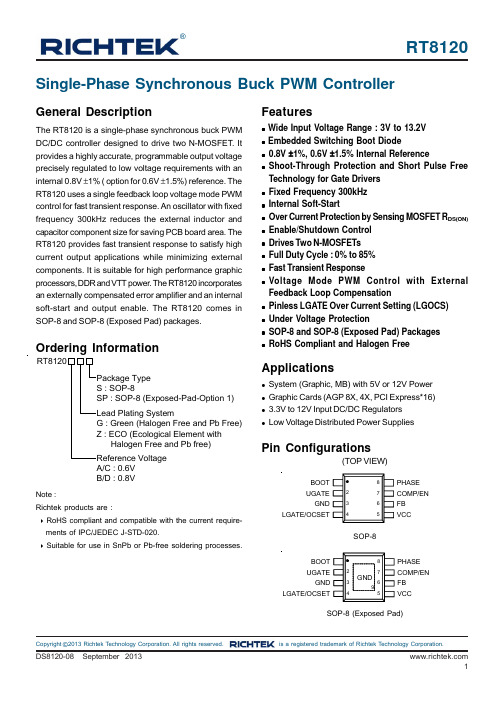
z System (Graphic, MB) with 5V or 12V Power z Graphic Cards (AGP 8X, 4X, PCI Express*16) z 3.3V to 12V Input DC/DC Regulators z Low Voltage Distributed Power Supplies
1
RT8120
Marking Information
RT8120xGS
RT8120x GSYMDNN
RT8120xGS : Product Number YMDNN : Date Code
RT8120xGSP
RT8120x GSPYMDNN
RT8120xGSP : Product Number YMDNN : Date Code
Ordering Information
RT8120
Package Type S : SOP-8 SP : SOP-8 (Exposed-Pad-Option 1)
Lead Plating System G : Green (Halogen Free and Pb Free) Z : ECO (Ecological Element with
RT8120xZS
RT8120x ZSYMDNN
RT8120xZS : Product Number YMDNN : Date Code
RT8120xZSP
RT8120x ZSPYMDNN
RT8120xZSP : Product Number YMDNN : Date Code
Typical Application Circuit
Technology for Gate Drivers z Fixed Frequency 300kHz z Internal Soft-Start z Over Current Protection by Sensing MOSFET RDS(ON) z Enable/Shutdown Control z Drives Two N-MOSFETs z Full Duty Cycle : 0% to 85% z Fast Transient Response z Voltage Mode PWM Control with External
ISO-UNI 管件 PVC-U 公制系列溶剂粘接管件说明书
ISO-UNI 管件PVC-U 公制系列溶剂粘接管件16管件通过使用溶剂和清洁剂底漆的冷化学粘接系统(溶剂粘接)输送压力流体的管件系列公制系列溶剂粘接管件ISO-UNI17PVC-U 管件的回归曲线故障时间技术数据工作温度温度-压力曲线图对于水和无害液体,材料归类为抗化学腐蚀(使用寿命 25 年)。
在其他情况下,需要降低公称压力 PN。
回归系数符合 EN ISO 1452 与 EN ISO 15493 规定的最小要求强度 (MRS) 值 = 25 N/mm 2 (MPa)(PVC-U 250 类别)18本说明书中提供的信息是真实的。
对于公认国际标准未直接涵盖的技术数据,FIP 概不负责。
FIP 保留进行任何修改的权利。
产品必须由合格人员进行安装和维修。
安全系数表中记录了每种压力等级随时间变化的安全系数。
作为计算和选择管件时使用的标准压力,公称压力 PN 必须易于理解。
为符合安全系数的要求,在 20°C 下输送水流时的最大连续工作压力必须与公称压力值相同。
除非另有规定,否则公称压力如下:•溶剂粘接管件d 12 - d 225 PN 16 d 250 - d 315 PN 10•转接器管件d 16 - d 110 PN 16•螺纹接头R 3/8”- R 4”至 PN 16该系列中的某些管件以 PN16 的形式出售,其安全系数小于 ISO 标准的规定。
*安全系数减小SIV带溶剂粘接承差口的 90°长半径弯头 (R=2d)I:IIP 122 H:KIWA K5034 ND 10*安全系数减小 (PN 10)19图 AI:IIP 122 F:AFNOR NF04 H:KIWA K5034 ND 10*安全系数减小 图 BGIV带溶剂粘接承插口的 90°弯头(图 B)*安全系数减小20HIV带溶剂粘接承插口的 45°弯头I:IIP 122 F:AFNOR NF04 H:KIWA K5034 ND 10**转售产品21MIV溶剂粘接直通I:IIP 122 F:AFNOR NF04 H:KIWA K5034 ND 10*安全系数减小**转售产品22TIV带溶剂粘接承插口的 90°三通YIV带溶剂粘接承插口的 45°三通**转售产品23TRIV带承插口的 90°异径三通**转售产品24XIV带溶剂粘接承插口的 90°四通H:KIWA K5034 ND 10 CIV带溶剂粘接承插口的端盖I:IIP 122 F:AFNOR NF04BIV带溶剂粘接承插口的活接,采用 EPDM 或 FPM 制 O 型圈EFV用于 BIV、BIFV、BFV、BLV、BIRV、BIFOV、BIROV、BIFXV、BIRXV 型接头的具有 BSP 螺纹的活接螺母F/BLV用于溶剂粘接的活接套筒,英制系列Q/BLV用于溶剂粘接的活接端,英制系列O 型圈用于 BIV、BIFV、BFV、BLV、BIRV、BIFOV、BIROV、BIFXV、BIRXV 型活接的 O 型圈RIV变径:溶剂粘接插端(d) 或溶剂粘接承插口(d 1 异径)I:IIP 122 F:AFNOR NF04RIV:质量标志参考尺寸 d 和 d 1RIV变径:溶剂粘接插端 (d) 或溶剂粘接承插口 (d 2)、溶剂粘接承插口(d 1 异径)或溶剂粘接插端(d 3 异径)I:IIP 122 F:AFNOR NF04RIV:质量标志参考尺寸 d 和 d1RIV变径:溶剂粘接插端 (d) 或溶剂粘接承插口 (d 2)、溶剂粘接承插口(d 1 异径)I:IIP 122 F:AFNOR NF04RIV:质量标志参考尺寸 d 和 d 1图 AMRIV变径:溶剂粘接承插口(图 A)*转售产品DIV补芯:带溶剂粘接插端 (d) 和溶剂粘接承插口(d 1 异径)(图 A)I:IIP 122 F:AFNOR NF04*安全系数减小**转售产品MRIV变径:溶剂粘接承插口(图 B)*安全系数减小图 B图 AI:IIP 122*转售产品DIV补芯:带溶剂粘接插端 (d) 和溶剂粘接承插口(d 1 异径)(图 B)图 BQPV带溶剂粘接承插口的平面法兰适配器符合 DIN 8063 PN 10/16 标准I:IIP 122*安全系数减小**转售产品***用于 FK-FE 蝶阀的特制法兰转接器QRV带溶剂粘接承插口的细齿面法兰适配器符合 DIN 8063 PN 10/16 标准,与 QPV/QRV 法兰转接器和平垫圈(参阅 QHV 查看垫圈尺寸)一起使用I:IIP 122*安全系数减小QHV/X用于法兰的 EPDM 和 FPM 制平垫圈符合 DIN 2501、EN1092 标准QHV/Y用于法兰的 EPDM 制平垫圈符合 DIN2501、EN1092 标准,自对中 PN 10/16 - DN150 - DN200 的 PN 10ODV用于 QPV、QRV、QLV EN/ISO/DIN 法兰适配器的法兰盘开孔:- PN 10/16 - DN150 - DN200 的 PN 10I:IIP 122*PMA 最大容许工作压力** 公称拧紧扭矩***转售产品*PMA 最大容许工作压力** 公称拧紧扭矩*PMA 最大容许工作压力*最大压力值符合 EN/ISO/DIN 标准。
ASTM D2466-2013
Designation:D2466−13An American National Standard Standard Specification forPoly(Vinyl Chloride)(PVC)Plastic Pipe Fittings,Schedule401This standard is issued under thefixed designation D2466;the number immediately following the designation indicates the year oforiginal adoption or,in the case of revision,the year of last revision.A number in parentheses indicates the year of last reapproval.Asuperscript epsilon(´)indicates an editorial change since the last revision or reapproval.This standard has been approved for use by agencies of the Department of Defense.1.Scope*1.1This specification covers poly(vinyl chloride)(PVC) Schedule40pipefittings.Included are requirements for materials,workmanship,dimensions,and burst pressure.N OTE1—Socket-type CPVC plastic pipefittings,Schedule40,which were formerly included in this standard,are now covered by Specification F438.1.2The products covered by this specification are intended for use with the distribution of pressurized liquids only,which are chemically compatible with the piping materials.Due to inherent hazards associated with testing components and sys-tems with compressed air or other compressed gases,some manufacturers do not allow pneumatic testing of their products. Consult with specific product/component manufacturers for their specific testing procedures prior to pneumatic testing.N OTE2—Pressurized(compressed)air or other compressed gases contain large amounts of stored energy which present serious saftey hazards should a system fail for any reason.1.3Fitting such as unions,flanges,special plastic-to-metal transitions and appurtenances intended for use with PVC piping are covered under specification F1970.1.4The text of this specification references notes,footnotes, and appendixes which provide explanatory material.These notes and footnotes(excluding those in tables andfigures)shall not be considered as requirements of the specification.1.5The values stated in inch-pound units are to be regarded as standard.The values given in parentheses are mathematical conversions to SI units that are provided for information only and are not considered standard.1.6The following safety hazards caveat pertains only to the test method portion,Section7,of this specification.This standard does not purport to address all of the safety concerns, if any,associated with its use.It is the responsibility of the user of this standard to establish appropriate safety and health practices and determine the applicability of regulatory limita-tions prior to use.2.Referenced Documents2.1ASTM Standards:2D618Practice for Conditioning Plastics for TestingD1599Test Method for Resistance to Short-Time Hydraulic Pressure of Plastic Pipe,Tubing,and FittingsD1600Terminology for Abbreviated Terms Relating to Plas-ticsD1784Specification for Rigid Poly(Vinyl Chloride)(PVC) Compounds and Chlorinated Poly(Vinyl Chloride) (CPVC)CompoundsD2122Test Method for Determining Dimensions of Ther-moplastic Pipe and FittingsD2749Symbols for Dimensions of Plastic Pipe FittingsF412Terminology Relating to Plastic Piping SystemsF438Specification for Socket-Type Chlorinated Poly(Vinyl Chloride)(CPVC)Plastic Pipe Fittings,Schedule40F1498Specification for Taper Pipe Threads60°for Thermo-plastic Pipe and FittingsF1970Specification for Special Engineered Fittings,Appur-tenances or Valves for use in Poly(Vinyl Chloride)(PVC) or Chlorinated Poly(Vinyl Chloride)(CPVC)Systems 2.2NSF Standards:Standard No.14for Plastic Piping Components and Related Materials3Standard No.61for Drinking Water Systems Components—Health Effects33.Terminology3.1General—Definitions are in accordance with Terminol-ogy F412,and abbreviations are in accordance with Terminol-ogy D1600,unless otherwise indicated.The abbreviation for poly(vinyl chloride)plastic is PVC.1This specification is under the jurisdiction of ASTM Committee F17on Plastic Piping Systems and is the direct responsibility of Subcommittee F17.10on Fittings.Current edition approved Aug.1,2013.Published September2013.Originally approved st previous edition approved in2006as D2466–06.DOI: 10.1520/D2466-13.2For referenced ASTM standards,visit the ASTM website,,or contact ASTM Customer Service at service@.For Annual Book of ASTM Standards volume information,refer to the standard’s Document Summary page on the ASTM website.3Available from NSF International,P.O.Box130140,789N.Dixboro Rd.,Ann Arbor,MI48113-0140.*A Summary of Changes section appears at the end of this standard Copyright©ASTM International,100Barr Harbor Drive,PO Box C700,West Conshohocken,PA19428-2959.United States--`,,``,,`,,,,,``,`,`,,,`,`,,,-`-`,,`,,`,`,,`---4.Classification4.1General—This specification covers Schedule40PVC pipefittings,made from four PVC plastic compounds and intended for use with Iron Pipe Size(IPS)outside-diameter plastic pipe.4.1.1Fittings covered by this specification are normally molded.In-linefittings,such as couplings,bushings,caps, nipples,etc.,shall be molded or machined from extruded stock.4.1.2Fittings fabricated by welding are not included in this specification.5.Materials5.1This specification covers PVC pipefittings made from five PVC plastics as classified in Specification D1784.These are PVC12454,12454,13354,11443,and14333.5.2Compound—The PVC plastic compound shall meet the requirements of PVC12454,12454,11443,or14333,as described in Specification D1784.N OTE3—Mechanical strength,heat resistance,flammability,and chemical resistance requirements are covered in Specification D1784. 5.3Rework Material—The manufacturers shall use only their own clean reworkfitting material and thefittings pro-duced shall meet all the requirements of this specification. 6.Requirements6.1Dimensions and Tolerances:6.1.1Fitting sockets inside diameters(waterways),mini-mum wall thicknesses,and dimensions shall be as shown in Table1,Table2,and Table3when measured in accordance with Test Method D2122.6.1.2When multistep reducer bushings are cored out,the inner socket shall be reinforced from the outer wall by a minimum of three ribs extending from the top of the inner socket to the deepest extremity of the coring.The transition from D to DJ(Table3)shall be straight,tapered as shown,or radiused.A positive taper in the same direction of the taper in the socket on the outside diameter of the bushing is optional (See XA/XB in Table3).Any point measured along the outside diameter of the bushing(between points XA and XB)shall not fall below minimum pipe OD.6.1.3The minimum wall thickness offittings shall be125% of the minimum wall thickness of the corresponding size of Schedule40pipe for which they are designed to be used, except that for the socket,the wall thickness shall be at least equal to the minimum wall thickness of the corresponding size of Schedule40pipe.For any threadedfitting the minimum wall thickness of the threaded portion shall be at least equal to the thickness of material under the thread root of threaded Sched-ule80pipe of the same size.6.1.4The minimum inside diameter of thefittings shall be not less than the minimum specified inside diameter of the corresponding size of Schedule40pipe.Anyfitting having a male thread shall have an internal diameter not larger than Schedule80pipe of the same size.6.1.5Minimum dimensions have zero negative tolerance. Tolerances on other dimensions are shown in Table1and Table 3.6.2Threads—For allfittings having taper pipe threads, threads shall conform to Specification F1498and be gaged in accordance with8.4.6.3Burst Pressure:6.3.1The minimum burst strength of thefittings shall be not less than that calculated for the size and wall thickness of the pipe with which it is to be used,when calculated from the following equation:S5P~D O2t!/2t(1) where:S=hoop stress,psi(or MPa),P=internal pressure,psi(or MPa),D O=average outside diameter,in.(or mm),andt=minimum wall thickness,in.(or mm).Fittings tested in accordance with8.5shall withstand the minimum burst pressure shown in Table4.6.3.2Pressures shown are minimum burst pressures and do not imply rated working pressures.The burst pressure shall be used only as an indication of quality.7.Workmanship,Finish,and Appearance7.1Thefittings shall be homogeneous throughout and free of cracks,holes,foreign inclusions,or other defects.The fittings shall be as uniform as commercially practicable in color,opacity,density,and other physical properties.8.Test Methods8.1Conditioning—Condition the test specimens at736 3.6°F(2362°C)and5065%relative humidity for not less than40h prior to test in accordance with Procedure A of Practice D618,for those tests where conditioning is required.8.2Test Conditions—Conduct tests in the Standard Labora-tory Atmosphere of7363.6°F(2362°C)and5065% relative humidity,unless otherwise specified in the test meth-ods or in this specification.8.3Sampling—A sufficient quantity offittings as agreed upon between the seller and the purchaser shall be selected at random from each lot or shipment and tested to determine that the basic design is in conformance with this specification.N OTE4—For individual orders or specifications,only those tests and numbers of tests specifically agreed upon between the purchaser and the seller need be conducted.8.4Threads—All taper pipe threads shall be gaged in accordance with Specification F1498.8.5Burst Pressure—Determine the minimum burst pressure in accordance with Test Method D1599.The pressure shall be applied at a uniform rate such that the minimum allowable burst pressure is attained in60or70s.N OTE5—The time-to-failure may exceed70s.8.5.1Apparatus—Fittings shall be tested while held in a test jig constructed in such a manner as to seal the socket by means of O-rings,or gaskets but not to reinforce or support the fittings,except where contact is necessary because of the shape of thefitting to keep thefitting in the test jig.Such contact shall be held to the minimum.The socket plug portion of thetest --`,,``,,`,,,,,``,`,`,,,`,`,,,-`-`,,`,,`,`,,`---fixture must extend one third to two thirds of the socket depth.Failure of any part of the test apparatus does not constitute failure of the fittings.9.Retest and Rejection9.1If the results of any test(s)do not meet the requirements of this specification,the tests(s)shall be conducted again only by agreement between the purchaser and seller.Under such agreement,minimum requirements shall not be lowered,changed,or modified,nor shall specification limits be changed.If upon retest,failure occurs,the quantity of product repre-sented by the test(s)does not meet the requirements of this specification.10.Marking10.1Fittings shall be marked with the following:10.1.1Manufacturer’s name or trademark,10.1.2Material designation PVC I for PVC 12454-B,PVC 12for PVC 12454-C,PVC 13for PVC 13354-C and11443-B,and PVC II for PVC 14333-D,TABLE 1Tapered Sockets for PVC Pipe Fittings,Schedule 40,in.ANominal Pipe SizeASocket Entrance Diameter BSocket Bottom Diameter C B Socket Length,min D C Inside Diameter,min Wall Thickness,minMin Outside Diameter of Hub,M Entrance,minDiameter Toleranceon Diameter Max Out-of-Round Diameter Toleranceon Diameter Max Out-of-Round E F EWEX,EZ1⁄80.417±0.0040.016(0.41)0.401±0.0040.016(0.41)0.5000.2250.0680.0850.5261⁄641⁄641⁄40.552±0.0040.016(0.41)0.536±0.0040.016(0.41)0.5000.3200.0880.1100.6721⁄641⁄643⁄80.687±0.0040.016(0.41)0.671±0.0040.016(0.41)0.5940.4490.0910.1140.8211⁄321⁄321⁄20.848±0.0040.016(0.41)0.836±0.0040.016(0.41)0.6880.5780.1090.1360.9981⁄321⁄323⁄4 1.058±0.0040.020(0.51) 1.046±0.0040.020(0.51)0.7190.7400.1130.141 1.2211⁄321⁄321 1.325±0.0050.020(0.51) 1.310±0.0050.020(0.51)0.8750.9900.1330.166 1.5041⁄161⁄1611⁄4 1.670±0.0050.024(0.61) 1.655±0.0050.024(0.61)0.938 1.3350.1400.175 1.8711⁄161⁄1611⁄2 1.912±0.0060.024(0.61) 1.894±0.0060.024(0.61) 1.094 1.5640.1450.181 2.1271⁄161⁄162 2.387±0.0060.024(0.61) 2.369±0.0060.024(0.61) 1.156 2.0210.1540.193 2.6341⁄161⁄1621⁄2 2.889±0.0070.030(0.76) 2.868±0.0070.030(0.76) 1.750 2.4140.2030.254 3.1703⁄321⁄83 3.516±0.0080.030(0.76) 3.492±0.0080.030(0.76) 1.875 3.0080.2160.270 3.8413⁄321⁄831⁄2 4.016±0.0080.030(0.76) 3.992±0.0080.030(0.76) 2.000 3.4860.2260.283 4.3743⁄321⁄84 4.518±0.0090.030(0.76) 4.491±0.0090.030(0.76) 2.000 3.9610.2370.296 4.9073⁄321⁄85 5.583±0.0100.060(1.52) 5.553±0.0100.060(1.52) 3.000 4.9750.2580.323 6.0393⁄321⁄86 6.647±0.0110.060(1.52) 6.614±0.0110.060(1.52) 3.000 5.9860.2800.3507.2031⁄83⁄1688.655±0.0150.090(2.29)8.610±0.0150.090(2.29) 4.0007.8880.3220.4039.3201⁄83⁄161010.780±0.0150.100(3.05)10.735±0.0150.100(3.05) 5.0009.9170.3650.45611.6141⁄83⁄161212.780±0.0150.120(3.81)12.735±0.0150.120(3.81)6.00011.8250.4060.50813.7861⁄83⁄16A The sketches and designs of fittings are illustrative only.BSocket depth,measured from socket entrance face to socket bottom face.CSee 6.1.4.N o r e p r o d u c t i o n o r n e t w o r k i n g p e r m i t t e d w i t h o u t l i c e n s e f r o m I H S10.1.3Fittings intended for the transport of potable water shall include the seal or mark of the laboratory making the evaluation for this purpose.10.1.4Size,and10.1.5This designation number:D2466.10.2Where the size of the fitting does not allow complete marking,omit identification marking in the following se-quence:size,material designation,manufacturer’s name or trademark.10.3Markings or symbols shall be molded,hot-stamped,or applied to fittings by any other suitable method,such as printing.10.4Where recessed marking is used,care shall be taken to see that in no case marking causes cracks or reduces the wall thickness below the minimum specified.11.Quality Assurance11.1When the product is marked with this designation,D2466,the manufacturer affirms that the product was manufactured,inspected,sampled,and tested in accordance with this specification and has been found to meet the requirements of this specification.12.Keywords12.1fittings;pressure;PVC;Sch 40;sockets;threadsTABLE 2Minimum Dimension from Center to End of Sockets (Laying Length)for Couplings,Tees,90°and 45°Elbows,PVCSocket-Type Pipe Fittings,Schedule 40,in.ANominal Pipe Size G ,minJ ,minN ,min 1⁄81⁄41⁄81⁄161⁄45⁄165⁄321⁄163⁄83⁄83⁄163⁄321⁄21⁄21⁄43⁄323⁄49⁄165⁄163⁄32111⁄165⁄163⁄3211⁄47⁄83⁄83⁄3211⁄217⁄163⁄32211⁄45⁄83⁄3221⁄211⁄211⁄163⁄163113⁄163⁄43⁄1631⁄221⁄813⁄16425⁄1613⁄165313⁄83⁄16631⁄213⁄41⁄4841⁄221⁄410513⁄1629⁄161⁄412615⁄1631⁄161⁄4AThe sketches and designs of fittings are illustrativeonly.--`,,``,,`,,,,,``,`,`,,,`,`,,,-`-`,,`,,`,`,,`---TABLE 3Dimensions of Reducer Bushings,PVC Socket-Type Pipe Fittings,Schedule 40,A in.(mm)Nominal Size Outside DiameterXA Tolerance on Outside Diameter Outside DiameterXB Tolerance on Outside Diameter Maximum Out-of-Roundness(max,minus min.)1⁄4by 1⁄80.540(13.72)+0.007–0.004(0.18–0.10)0.540(13.72)±0.004(0.10)0.016(0.41)3⁄8by 1⁄4,1⁄80.675(17.41)+0.007–0.004(0.18–0.10)0.675(17.41)±0.004(0.10)0.016(0.41)1⁄2by 3⁄8,1⁄40.840(21.34)+0.007–0.004(0.18–0.10)0.840(21.34)±0.004(0.10)0.016(0.41)3⁄4by 1⁄2,3⁄8,1⁄41.050(26.67)+0.007–0.004(0.18–0.10) 1.050(26.67)±0.004(0.10)0.020(0.51)1by 1⁄2,3⁄4 1.315(33.40)+0.008–0.005(0.20–0.13) 1.315(33.40)±0.005(0.13)0.020(0.51)11⁄4by 1⁄2,3⁄4,1 1.660(42.16)+0.008–0.005(0.20–0.13) 1.660(42.16)±0.005(0.13)0.024(0.61)11⁄2by 1⁄2,3⁄4,1,11⁄4 1.900(48.26)+0.010–0.006(0.25–0.15) 1.900(48.26)±0.006(0.15)0.024(0.61)2by 1⁄2,3⁄4,1,11⁄4,11⁄22.375(60.33)+0.010–0.006(0.25–0.15) 2.375(60.33)±0.006(0.15)0.024(0.61)21⁄2by 2 2.875(73.03)+0.012–0.007(0.30–0.18) 2.875(73.03)±0.007(0.18)0.030(0.76)3by 21⁄2,2 3.500(88.90)+0.013–0.008(0.33–0.20) 3.500(88.90)±0.008(0.20)0.030(0.76)31⁄2by 21⁄2,24.000(101.60)+0.013–0.008(0.33–0.20) 4.000(101.60)±0.008(0.20)0.030(0.76)4by 31⁄2,3,21⁄2,24.500(114.30)+0.015–0.009(0.38–0.23) 4.500(114.30)±0.009(0.23)0.030(0.76)5by 45.563(141.30)+0.017–0.010(0.43–0.25) 5.563(141.30)±0.010(0.25)0.060(1.52)6by 56.625(168.28)+0.018–0.011(0.46–0.28) 6.625(168.28)±0.011(0.28)0.070(1.78)8by 68.625(219.08)+0.025–0.015(0.64–0.38)8.625(219.08)±0.015(0.38)0.090(2.29)10by 610.750(273.05)+0.025–0.015(0.64–0.38)10.750(273.05)±0.015(0.38)0.100(2.54)10by 810.750(273.05)+0.025–0.015(0.64–0.38)10.750(273.05)±0.015(0.38)0.100(2.54)12by 612.750(323.85)+0.025–0.015(0.64–0.38)12.750(323.85)±0.015(0.38)0.120(3.05)12by 812.750(323.85)+0.025–0.015(0.64–0.38)12.750(323.85)±0.015(0.38)0.120(3.05)12by 1012.750(323.85)+0.025–0.015(0.64–0.38)12.750(323.85)±0.015(0.38)0.120(3.05)AThe sketches and designs of fittings are illustrative only,see Symbols D2749.TABLE 4Burst Pressure Requirements for Water at 73°F (23°C)for PVC Socket-Type Pipe Fittings,Schedule 40Nominal Size,in.Min Burst Strength,AClasses 12454,13354-C,and 11443Class 14333psi (MPa)psi (MPa)1⁄82580(17.79)2020(13.93)1⁄42490(17.17)1950(13.44)3⁄81990(13.72)1560(10.76)1⁄21910(13.17)1490(10.27)3⁄41540(10.62)1210(8.34)11440(9.93)1130(7.79)11⁄41180(8.14)920(6.34)11⁄21060(7.31)830(5.72)2890(6.14)690(4.76)21⁄2970(6.69)760(5.24)3840(5.79)660(4.55)31⁄2770(5.31)600(4.14)4710(4.90)560(3.86)5620(4.27)490(3.38)6560(3.86)440(3.03)8500(3.45)390(2.69)10450 3.10 (12)4202.90......AThis table was calculated for Schedule 40pipe using the formula and the stress levels for materials as follows:psi MPaClasses 11443,13354-C,and 12454640044.1Class 1433500034.5--`,,``,,`,,,,,``,`,`,,,`,`,,,-`-`,,`,,`,`,,`---SUPPLEMENTARY REQUIREMENTSPOTABLE WATER REQUIREMENTThis requirement applies whenever a Regulatory Authority or user calls for product to be used toconvey or to be in contact with potable water.S1.Products intended for contact with potable water shall be evaluated,tested and certified for conformance with ANSI/ NSF Standard No.61or the health effects portion of NSF Standard No.14by an acceptable certifying organization when required by the regulatory authority having jurisdiction.SUMMARY OF CHANGESCommittee F17has identified the location of selected changes to this standard since the last issue(D2466–06) that may impact the use of this standard.(1)Added language to6.1.2to clarify the minimum outerdimension of the spigot portion of a bushing.ASTM International takes no position respecting the validity of any patent rights asserted in connection with any item mentioned in this ers of this standard are expressly advised that determination of the validity of any such patent rights,and the riskof infringement of such rights,are entirely their own responsibility.This standard is subject to revision at any time by the responsible technical committee and must be reviewed everyfive years and if not revised,either reapproved or withdrawn.Your comments are invited either for revision of this standard or for additional standards and should be addressed to ASTM International Headquarters.Your comments will receive careful consideration at a meeting of the responsible technical committee,which you may attend.If you feel that your comments have not received a fair hearing you should make your views known to the ASTM Committee on Standards,at the address shown below.This standard is copyrighted by ASTM International,100Barr Harbor Drive,PO Box C700,West Conshohocken,PA19428-2959, United States.Individual reprints(single or multiple copies)of this standard may be obtained by contacting ASTM at the above address or at610-832-9585(phone),610-832-9555(fax),or service@(e-mail);or through the ASTM website ().Permission rights to photocopy the standard may also be secured from the ASTM website(/COPYRIGHT/).N o r e p r o d u c t i o n o r n e t w o r k i n g p e r m i t t e d w i t h o u t l i c e n s e f r o m I H S。
施工常用词汇
chin strap(安全帽)帽带creepage(表面)漏电jacket(电缆)夹套(层)paper masking tape(盖焊缝用)纸胶布foreman (all crafts)(各专业)工头air-entrainment admixture(混凝土)加气剂agitator truck(混凝土)搅拌运输车alternate-bay construction(混凝土路面)隔仓施工法belt finish(混凝土路面)皮带拖平cross ledger(脚手架)横杆upstream(介质)上游downstream(介质)下游screed (抹灰)刮板metal lath(抹灰用)金属拉网bleeding cement(水泥)浮浆recruitment plan(新成员)征招方案bridge, crane(行车的)大车hoist, trolley(行车的)小车to build up a passivation film by adding chemicals(循环水)预膜compressed gas cylinder(压缩)气瓶O-ring“O”形环A/D converter A/D(交直流)转换器H-beam H型钢n strand erecting solid conductor n股绞合线(电缆用语)n conductor cable n芯电缆PTFE thread seal tape PTFE丝扣密封带PVC black tape PVC黑胶布T-joint T形接头t-type strainer T型滤网clevis U形夹bulldozer U形弯筋机X-ray X射线star Y型接线y-type strainer Y型滤网safety and security安全保卫safety promotion campaign安全促进活动safety harness, safety belt安全带safety valve安全阀PRV pop test record sheet安全阀校验记录单safe work practices安全工作惯例safety & security officer安全官safety supervisor安全管理人员tool box meeting;safety meeting安全会safety incentives安全激励safety and health deficiencies安全健康不符合要求safety and health consciousness安全健康意识safety award安全奖safety indoctrination安全教育safety competitions 安全竞赛safety glasses安全镜hard hat; safety helmet安全帽safety target安全目标an in-depth safety review meeting安全深入检查会safety visibility campaign安全透明度活动safety net安全网relief valve安全泄压阀safety boot安全靴(鞋)safety precautions安全预防措施safety officer /supervisor安全员monthly safety report安全月报barrier panel安全栅盘installation/erection安装erection opening安装预留孔bund岸墙push button按钮rocker handle integral switch按钮搬倒开关level handle built-up switch按钮式组合开关itemized by area and craft按区域和工种分类dip switch暗藏插头coped joint暗缝blind drainage暗沟排水pit凹坑irregularities凹凸不平处valleys凹陷concave fillet weld凹形角焊缝female adapter凹形适配器austenite奥氏体austenitic stainless steel奥氏体不锈钢octagonal ring gasket八角形金属环连接垫片spectacle blind八字盲板manual take-off of material扒料collet body把芯子target plate靶板target type meter靶式流量计clear glass白玻璃incandescent tungsten filament lamp白炽灯fish eye白点stainless steel白钢whitelight白光sheet metal worker白铁工tinned iron; tin plate白铁皮dial gage 百分表louver百叶窗louver百叶窗weave bead摆动焊道wobulator摆频振荡器spanner/wrench扳手foreman班长handling搬运planks板材stock guide板料导向块crating板条箱pipe machine die板牙revision版次half key coupling半键式联轴器semimetallic gasket半金属垫片radius半径half coupling半螺纹管箍semigraphic annunciator半模拟式报警器half round file 半园锉semi-automatic welding半自动焊heat tracing伴热tracing piping伴热管tracing and insulation伴热与保温ready mix truck拌运车binding reinforcement绑扎钢筋tie wire绑扎用铁丝die grinder棒式磨光机curb angle包边角钢cladding包层iron worker包铁工package包装shielded gas保护气体shield gas flow rate保护气体流量protective cap or cover保护塞或盖protective coating保护涂层shroud保护罩cold preservation 保冷security保卫insulation保温insulation pin保温钉insulation fitter; insulation worker保温工insulation module保温模块soaking time保温时间blanket insulation保温毡tag line保险绳alarm function报警功能alarm circuit报警回路alarm bridge报警桥路pall ring鲍尔环rupture disk爆破膜blast cleaning爆破清洗blast valve爆炸阀explosion welding爆炸焊backing strip背垫条back pressure背压intrinsical本征电导的intrinsic safety barrier本质安全防爆栅pump泵pump package泵包pump well泵坑motor for pump泵用马达turbine for pump泵用透平ratio block比例系数块bit比特specific gravity比重everyday penlight笔式电筒grating箅子板panel壁板schedule number壁厚wall paper壁纸wall mounted lamp壁装照明设施gratings篦子板lightning protection避雷保护arrester避雷器air termination, lightening rod, lightning arreste避雷针boundary survey边界勘测edge distance边距marshalling cabinet编组柜spreader beam扁担flat bar扁钢catwalk便道portable potentiometer便携式电位仪portable oscilloscope便携式示波器substation变电所revision; change; modification变更change order; modification notification变更单variable area flowmeter变容流量计transmittor 变送器transmitter simulator变送器模拟器variable speed controller变速控制器gear box变速箱 deformed; distorted变形的transformer变压器scale signal标尺信号elevation标高logo symbol标记tag line标记线identification marking; identification tape marker标识sign board标识牌marking tape标识圈带proposal标书logo; sign标志standard标准bench mark标准检查程序basic calibration block标准块snuffing steam标准蒸汽apparent density表观密度contacts of gauge表接触器surface preparation表面处理exposed slag表面夹渣manometer pressure表压mask表征码acetone丙酮ABS= acrylonitrile butadiene styrene丙烯腈-丁二烯-苯乙烯共聚塑料calcium-acrylate treatment丙烯酸钙处理(化学灌浆)acrylic丙烯酸类shunt field并联磁场chain intermittent fillet weld并列断续角焊缝Portland cement concrete波特兰水泥混凝土baud rate波特率corrugated board 波纹板bellows波纹管bellows meter波纹管流量计glass panel heater玻璃板加热器glass wool玻璃棉glass fiber玻璃纤维scaling; stripping剥落platformer铂重整dust pan簸箕compole补偿磁极compensating cable; extension wire补偿导线makeup compressor补偿式压缩机repair welding补焊touch-up补漆irregularity不规则处UPS:uninterrupted power supply不间断电源watertight不漏水的stainless steel不锈钢nonconformance/discrepancy不一致处out-of-roundness不圆度cloth masking tape布胶带layout布置walkie-talkie步话机step-by-step welding步进缝焊partial acceptance部分验收component部件MSDS:Material Safety Data Sheet材料安全数据页material cotroller材料保管员bill of material材料表material substitution材料代用material order材料订单norm for estimating material requirements材料定额material shortage材料短缺material requisition材料请购单outstanding material材料缺口material take-off材料统计DOT= Department of Treasury财政部space electric heater采暖电热器debris残屑residual hydrogen残余氢aftertrack残余粘性warehouse仓库warehouse keeper仓库保管员warehouse and material supervisor仓库与材料管理人员bulkhead舱壁operator操作工performance操作技能console操作台operational plant areas操作装置区drum槽channel(bar)槽钢slot welding槽焊side wall lack of fusion侧壁未熔合fillet weld in parallel shear侧面角焊缝toilet厕所altitude level测高水准仪surveyer测量工test pen测温笔incomplete inter-run penetration层间未焊透lack of fusion between adjacent passes 层间未熔合Inter-pass temperature层间温度fork lift叉车fork-indent-type lug叉式接线片plug插头plug in latch type connector插销型连接器receptacle; socket插座line check查线line checker查线人员differential manometer差示(动)压力计DP transmitter差压变送器differential pressure gauge差压压力表dif primary elements差压一次元件diesel fuel柴油GO-HDS: gas oil hydrogen desulphurisation柴油加氢脱硫spiral wound gasket缠绕垫片long radius 长半径long radius elbow长半径弯头long back cap长背帽NO or NC trouble contacts常开或常闭式事故触点ordinary pressure常压yard场地offsite场外oversize超/大尺寸superplasticizer超级增塑剂ultrasonic welding超声波焊ultrasonic flowmeter超声波流量计ultrasonic inspection超声波探伤ultra-rapid trip超速跳闸override超限override control超限控制over pressure超压shop painting 车间刷漆shop drawing车间制造图evacuation plan撤离方案settlement, subsidence沉降counter-sunk tapping screw沉头锁紧螺丝caisson沉箱twilight sensor晨昏启明器welding with backing衬垫焊lining; refractory衬里cost supervisor成本核算管理人员cost & estimation engineer成本预算工程师stranded leads成股导线contractor承包商socket weld承插焊socklet承插接管台bell and spigot承插口bearing stratum承压层bearing stress承压应力strength weld承载焊缝bearing plate承重板bearing wall承重墙city layout城市规划solid metal serrated gasket齿形金属垫片finned heater翅片式加热器purging充氮保护nitrogen purge充氮保护charger充电器oil filled cable充油电缆stroke冲程impact drill冲击钻punch冲孔rinse冲洗flush valve冲泄阀center punch; drift pin冲子spot check抽检tube bundle puller抽芯机consistency稠度move off出场outlet出口outlet line出口管线entry road, access road出入道路black annealing初(粗)退火dropping point初馏点initial set/ hardening初凝an initial indoctrination初期安全灌输preliminary alignment初找正deaerator除气器demister除雾器demister除雾器storage储存storage time/ shelf life储存寿命handling处理electric shock触电shock hazard触电危险drift pin穿孔器pinion传动(小)齿轮 transducer传感器belt conveyor传送带fillet welding in the flat position船形焊surge喘振series field串联磁场series-spot welding串联点焊window frame窗框soot blower吹灰器blowout 吹扫vertical 垂直的plumbness垂直度vertical deviation垂直偏差hammer drill锤钻pureness, fineness纯度alkyd醇酸树脂ceramic nozzle瓷喷嘴ceramic tile瓷砖magnetic field磁场field(=stator) coils磁场(定子)线圈magnetic particle inspection磁粉探伤magnetic stand磁力表架magnetic blow磁偏吹flux磁通量magnetic gauge磁性测厚仪hysteresis coefficient磁滞系数hysteresis磁滞现象secondary member次级构件girder次梁bullgear从动齿轮roughness粗糙coarse aggregate粗集料boulder粗砾accelerator促凝剂catalyst tube催化剂管embrittlement脆化brittle fracture脆性断裂tempering淬火diameter inch寸Doffset错边pilot valve错气阀overlap搭接film mark搭接标记overlapping single beading with concealed end 搭接带隐藏端的单筋缝overlapping single beading搭接单筋缝lap welding搭接焊lap joint搭接接头overlapping double beading搭接双筋缝toggle搭扣backing welding打底焊backing run打底焊道uranami welding electrode打底焊条stenciling打钢印spark gun打火枪puncher打孔器paved area打了竖向的地面grinding打磨wet down打湿pile driving; piling打桩pile driver打桩机typist打字员bull gear大齿轮high wind大风large bore大管marble大理石bulk concrete大体积混凝土reducing flange大小法兰reducer大小头tab lock washer带调整片(柄)防松垫圈strip surfacing带极堆焊band saw带锯welding helmet with flip-up lens带上翻透镜焊接护罩SWSI(single wall single image)单壁单影single-pass welding单道焊monorail beam单轨梁solo test run单机试运mono test-run单机试运singlestage horizontal pump单级卧式泵indirect spot welding单面点焊welding by one side单面焊single groove单面坡口unit project单位工程isometric单线图single line diagram单线图check valve单向阀item project单项工程single argon cylinder trolley单氩气瓶小推车spring washer弹簧垫圈spring hanger弹簧吊架modulus of elasticity弹性模数elastomeric弹性体nitrogen gas seal氮气密封stopper挡板支架break wind挡风墙stop挡块chock log挡木splashboard挡泥板shelter挡棚shield挡水(泥)板bulkhead, retaining wall挡土墙(板)knife blade type fuse刀片式熔断器conductivity probe导电性测量探头wire guide导电嘴pilot valve导阀conduit; tremie导管conduit导管condulet导管接头chain block导链guide vane导流叶片conductor导体conduit stub-up导线管短管wireway导线通道wire ampacity导线载流量guide support导向支架tubing导压管tubing reducer导压管大小头tubing union导压管活接头tubing tee导压管三通tubing bend导压管弯通tubing elbow导压管弯头guide pile导桩tumbler switch倒扳开关reversing alarm倒车警报chamfer倒角chain block倒链rodding捣实delivered as bulk materials到货为散件receiving inspection到货验收roadway道路equal percentage flow characteristics等百分比流量特性plasma machine等离子(切割)机plasma arc surfacing等离子弧堆焊plasma arc welding等离子弧焊plasma cutting等离子弧切割equivalent line size等效管径low-fume and harmfulness electrode低尘低毒焊条low hydrogen type electrode低氢型焊条cryogenic pump低温泵low voltage wiring低压接线low voltage control wiring低压控制接线bulkhead, bank, embankment, bund堤岸abrupt ridges 滴瘤weep hole滴水孔base plate底板uranami welding electrode底层焊条primer; prime paint底漆footing; skid底座base ring底座圈floor地板truck scale pit地磅坑gutter地沟anchor bolt地脚螺栓anchor bolt地脚螺栓drain funnel ; floor drain地漏aboveground地面ground penetration地面穿孔belowgrade地面以下grade地坪aboveground地上rug/carpeting地毯carpet strip地毯板条underground piping; underground line地下管道underground drainage地下排污basement地下室earth 地线topographic survey地质勘测submittal递交文件point-to-point check点对点检查spot welding; tack welding点焊tack weld点焊缝tacker点焊工ignition点火spot examination 点检查head counting; roll call点名electric tracing电伴热battery电池battery rack电池柜electric hammer电锤solenoid valve电磁阀solenoid valve电磁阀magnetic flow meter电磁流量计magnetic starter电磁起动器conductance level switch电导式液位开关conductivity电导性power tool电动工具motor starting capacitor电动机起动电容motor starting auto transformer电动机起动自动变压器electrician电工electrode holder电焊把welding cable电焊把线arc strike电弧擦伤arc spot welding电弧点焊arc voltage电弧电压dynamic characteristic of arc电弧动特性arc welding电弧焊arc force电弧力arc blow电弧偏吹arc gouging电弧气刨arc stiffness电弧挺度arc stability电弧稳定性arc self-regulation 电弧自身调节holiday test电火花试验armature电机转子electrode电极electrode skid电极滑移electrode contact surface电极接触面insert electrode tip电极头electrode pressure电极压力electrode pick-up电极粘损dielectric heater电介质加热器reactive circuit电抗(反馈)电路reactive电抗(性)的EPROM: electrically programmable read only memory电可编程序只读存贮器cable reel电缆缠绕机(盘) conduit电缆导线管cable locator电缆定位器cable gland电缆格兰raceway电缆管道trough电缆架cable joint电缆快速接头cable pulling compound电缆铺设润滑膏剂cable tray电缆桥架cable bundle电缆束cable gland电缆压盖cable clamp or strap电缆扎带cable shoe电缆终端(套管)soldering iron电烙铁current transformer电流互感器heat boiler/electric heater电炉electrical电气electropneumatic positioner电气定位器electric room电气间electrical wiring电气接线electric building电气楼electrical work permit电气施工许可证capacitor motor电容起动机condenser discharge spot welding电容贮能点焊fall-of-potential电势降armature电枢armature(=rotor) coils电枢(转子)线圈armature core电枢铁心telecommunication distribution system电讯系统voltage regulating relay电压调整继电器power receptacle电源插座electro-slag welding电渣焊electronic recorder电子记录仪electron beam welding电子束焊EIA: electronic instrument association电子仪表协会upset butt welding电阻对焊resistance welding电阻焊resistance temperature detector(RTD)电组温度检测器electric drill 电钻bearing plate; pad; filler垫板cushion course; mat垫层spacer垫隔圈gasket垫片washer垫圈shim垫铁cushion pile垫桩crane吊车crane safety load indicator , 吊车安全载荷指示器crane rail; crane girder;crane beam;overhead crane吊车轨(梁)crane operator 吊车司机crane banksman吊车指挥员lifting lug吊耳boom吊杆davit吊杆eye bolt吊环螺栓hanger吊架cradle /lifting cage吊篮sling吊索lift吊装crane operators daily check-list吊装操作工日常检查清单lifting belt; webbing sling吊装带coordinator调度ready mix paint调合漆regulating transformer调节变压器control valve调节阀regulator调节器blender调漆刷overhang调伸长度pressure relief cutouts调压断电器offset/bias调整偏差straightener调直机modem(modulator-demodulator)调制解调器drop-indicator relay掉牌继电器fall protection跌落防护butterfly valve蝶阀header丁砖mild steel tee bar; tee丁字钢stapler钉书机staple钉书机针nailed strip钉条roofing顶top angle顶部包边角钢over-head electrical service顶部电气作业upset顶锻upset force顶锻力upset allowance顶锻留量upset time顶锻时间header顶梁ceiling顶棚jacking screw顶丝PO= purchase order定单regular inspection 定期检查timer set定时元件tack welding定位焊tack weld定位焊缝set screw定位螺丝positioner定位器alignment stake; guide pile定位桩set pressure定压customized定制的stator定子绕组cherry picker动臂装卸机hot work permit动火施工许可证 hot work动火作业motor operated valve动力阀live load动载MSSS(motion stopping safety system)动作停止安全系统bowl scraper斗式铲运机bucket type strainer斗型滤网Charpy impact杜比(摆锤式)冲击zinc plated镀锌galvanized surface repair镀锌表面返修galvanized镀锌的galvanized steel镀锌钢RGS (rigid galvanized steel)conduit镀锌钢制导线管end to end端部至端部terminating端接termination kits端接工具箱edge weld端接焊缝edge joint端接接头endwall端墙terminal strip端子带terminal端子衔接套,接线片terminal pad端子座short radius elbow短半径弯头short back cap短背帽spool piece短管nipple 短节short-circuit brush短路电刷short circuiting transfer短路过渡breaker断路器breaker断路器intermittent welding断续焊forged steel锻钢forge time锻压时间wrought锻制的laydown 堆放场surfacing /build up welding堆焊welding neck flange对焊法兰welding neck orifice对焊孔板conversational machine; walkie talkie对讲机butt weld对接焊butt joint对接接头convection对流root face钝边blunt back –saw blade钝锯条multi bead multi pass weld多层多道焊multi-layer welding多层焊multi-pass welding多道焊multiple-spot welding多点焊multiple projection welding多点凸焊multi-core twisted cable多股绞合电缆perforated pipe多孔管multiple-wire submerged arc welding多丝埋弧焊multi-conductor cable多芯电缆inert-gas arc welding惰性气体保护焊gooseneck faucet鹅颈水嘴rated load额定负荷pop pressure额定压力reactive coil扼流圈inclement weather恶劣天气horseplay恶作剧crocodile clip鳄鱼夹ear plug耳塞ear plug耳塞trunnion耳轴secondary grouting二次灌浆secondary circuit二次回路xylene二甲苯molicote二硫化钼freon (CCL2F2)二氯二氟甲烷致冷剂carbon -dioxide arc welding二氧化碳气体保护焊delivery发货mildew present发霉issuing authorities发证主管部门valve flap阀瓣valve bush 阀衬valve spool阀杆valve stem阀杆valve bonnet; valve cap阀帽valve阀门valve stroke阀门(杆)行程valve clogging阀门结污valve diaphragm阀门膜板valve trim阀门内可操作部件valve chest阀门室valve lapping machine阀门研磨机valve actuator阀门执行机构valve land 阀面valve body阀体valve leakage阀泄漏valve cone; valve plug阀芯valve core阀芯valve key阀钥匙valve lag阀滞后valve gear阀装置manifolds阀组valve seat阀座valve base阀座flange法兰flange cap法兰保温盒flange adapter法兰适配器canvas帆布stub end翻边短管lap joint flange翻边法兰dumper翻斗车laitance翻沫Vaseline凡士林alumina矾土back hoe反铲挖土机reverse air blower反吹风backdraught反风流reversed polarity反接camber反挠reactor反应器reverse water返水repair返修bleeding泛浆flashing泛水square ; square bar方钢calcareous spar方解石orientation方位bursting discs防爆膜vapor barrier防潮层dusttight防尘的dust mask防尘面具anti-surge valve防喘振阀sag rod防垂杆break wind防风林weathertight防风雨weatherproof shelter防风雨棚holiday test防腐绝缘测漏试验winterization防寒处理cleat防滑条fire protection and prevention防火fire cloth防火布spark catch/arrester防火帽fire resistance clothing 防火衣服fire arms防火装备backsplash防溅背板static proof防静电waterproof marking防水标识watertight防水的Lock-washer防松垫圈insulation防烫保温personal protection insulation防烫伤隔热anti-bounce device防跳动机构rust-inhibiting film防锈膜anti-rust coating防锈涂料flashing防雨板anti-seize compound防粘膏bumper post防撞柱premises房产building line房基线vent line放空管线vent line放空线bleed valve放气阀exothermic connection放热接头lofting放样upset metal飞边spatters飞溅spatter loss coefficient飞溅率nonintrinsic safety barrier非本质安全防爆栅special support非标支架connective weld非承载焊缝non-ex junction box非防爆接线盒nonmetallic非金属的non-metallic gasket非金属垫片Nongraphic annunciator非模拟式报警器nonconsumable electrode非熔化电极non-smoking area非吸烟区nonlinearity非线性non designated smoking areas非指定吸烟区nontransferred arc非转移弧scrap metals废金属exhaust gas废气refuse and debris废物及残渣cost allocation费用分摊subcontractor分包商decibel分贝sub-unit project分部工程lamination分层split range controller分程调节器split range settings分程设定值lane line分道线block sequence welding分段多层焊back step sequence分段退焊spectroscope分光镜breakdown分解表separator分离器shunting分流shunt meter分流流量计distributor分配器distribution drum分汽缸DCS: distributed control system分散控制系统analyzer分析仪analyzer vent header分析仪放空集管sample dryer分析仪干燥器analyzer panel分析仪盘analyzer sample line分析仪取样管线analyzer gas分析仪用气split-phase motor分相电动机sub-item project分项工程molecular sieve分子筛fly ash粉煤灰plump bob string粉线weathering风化fan风机fan风扇vane风向标essential balm风油精back weld封底焊道topping out封顶seam welding缝焊hand rail扶栏freon (ccl2f2)氟利昂laitance layer浮浆层laitance浮浆皮displacer; float drum浮筒level displacer浮筒液位计buoyancy level transmitter浮子液位传送器welfare facility福利设施radiant heater辐射加热器auxiliary pump辅助泵electrode travel辅助行程corrosion腐蚀corrosion allowance腐蚀余量elevated zero setting ; span suppression负迁移fringe benefit附加费用tinctorial power附着力tandem mixer复式搅拌机by-product副产品zinc-rich primer富锌底漆assignment赋值web腹板web member腹杆cladding覆面screw driver改锥capping盖面norm for preliminary estimates概算定额summary概要beaten-cob construction干打垒a dry leg on the minus side干负侧支管dry film gauge干膜测厚仪DFT= dry film thickness干膜厚度dry gas seal干气密封dry coating thickness干涂层厚度desiccant干燥剂drier干燥器drying equipment干燥设备drying time 干燥时间direction of induced voltage感应电压方向steel clavis钢U型卡plate lifting clamp钢板吊装抱卡corrugated steel pipe钢波纹管steel hanger钢吊架armored glass钢化玻璃steel structural 钢结构SSPC: Steel Structure Painting Council钢结构油漆委员会rebar: reinforcing bar钢筋rebar protective cap钢筋保护帽bar spacer钢筋定位间隔块rebar worker钢筋工reinforced concrete钢筋混凝土floor slab钢筋混凝土结构地面板CRSI= concrete reinforcing steel institute钢筋混凝土学会(美)cage of reinforcement钢筋笼bar cutter钢筋切断机angle bender钢筋弯曲机steel tape钢卷尺steel stud钢立筋(龙骨)beam clamp 钢梁抱卡steel billet钢坯keyhole saw钢丝锯wire cutter钢丝钳wire rope钢丝绳wire brush钢丝刷hand wire brushing 钢丝刷手工(除锈)wire mesh; woven wire; woven-wire fabric钢丝网WRI: Wire Reinforcement Institute钢丝网学会stamp; stencile钢印elastomeric高弹材料high work/ elevated work高空作业blast furnace slag高炉矿渣HDPE: high-density polyethylene高密度聚乙烯H.F. resistance welding高频电阻焊over-head tank高位油箱pyrometers高温计penthouse 阁楼式顶棚bulkhead, partition plate隔板bin-wall隔仓式挡土墙partition隔断isolating drum隔离缸spacer隔离圈isolating gap隔离隙diaphragm valve隔膜阀diaphragm valve隔膜阀thermal insulation隔热blanket insulation隔热毡acoustical barrier/block隔声板bond breaker隔粘剂personal protective equipment个人劳动保护设备Chro-molly; chrome nickle steel铬钼钢concave root surface(suck-up); root concavity根部凹陷root radius根部半径root pass根部焊道root gap根部间隙incomplete root penetration根部未焊透locker room更衣室correction更正foreman工长plant air工厂风PEC: Plant Engineering Construction Pte Ltd工厂工程建设私人有限公司bill of quantities工程量表engineering工程设计engineer工程师canteen工地食堂work piece工件tradesman/craftsman工匠tool工具tool box工具箱industrial class工业纯industrial wastewater 工业废水process parameter工艺参数PCC(process control computer)工艺控制计算机PEFS: Process Engineering Flow Scheme工艺流程图workmanship工艺水平trade;discipline工种construction devices工装卡具I beam工字钢web工字梁腹scope of work工作范围working uniform工作服working load limit工作负荷极限work demarcation工作划分work volume工作量working platform, catwalk工作平台Bench; worktop工作台operational stroke工作行程work permit工作许可证work execution工作执行hacksaw弓形锯tolerance公差nominal dimensions公称尺寸in-house safety training公司内部安全培训in-house company procedure公司内部程序utility公用事业UEFS: utility engineering flow scheme公用事业流程图male and female公子与母子power recovery turbine功率恢复透平tap攻丝water supply供水oil supply pipe供油管arch beam拱梁pointing勾缝trench沟ground guide沟边挡板shackle钩环member构件takeoff估算工料stirrup箍筋aggregate骨料sags鼓包blower鼓风机mounting rails for terminals固定端子架fixed fire system固定防火系统field weld固定口retainer nut固定螺母fixed fire equipment固定消防设备anchor support固定支架solid solution固溶体fail-safe故障保险oil scraper ring刮油器pad lock挂锁milestone schedule关键控制点计划Pipe; tubing管line mixer管道(在线)混合器piping tracing管道伴热PFI= Pipe Fabricator's Institute管道制造商学会pipe locator管定位器pipe sleeper; sleeper rack管墩pipe fitter管工fitters' gloves管工手套coupling管箍piping welder管焊pipe rack管架coupling管接头adapter管接头pipe frame管框架supervisor管理人员pipe wrench管钳tubular heater管式加热器pipe shoe管托pipe 管线reinstatement管线复位line index管线索引pipe support管支架stanchion管柱FCAW= flux-cored arc welding管状焊丝电弧焊nipolet管嘴接管台nipple outlet管嘴接管台inertia switch惯性开关grouting灌浆tank罐tank fitter罐安装工tank strapping(to confirm dim check)罐的标定roof angle ring罐顶包边角钢cursor keys光标键photo electric光电的smooth uniform color光滑一致颜色smooth finish光面spectrum光谱hex mesh龟甲网checking龟裂procedure规程code规范sodium silicate硅酸钠Portland cement concrete硅酸盐水泥混凝土orbitally welded system轨道式自动焊接系统valuable but vulnerable equipment贵重易损设备plate roller滚板机roller-spot welding滚点焊circular electrode滚轮电极roller滚刷to be applied by roller 滚涂roller滚子boiler accessory锅炉辅助设备boiler failure锅炉故障boiler scale 锅炉水锈NEC= National Electrical Code国家电气规范NFPA= National Fire Protection Association国家防火协会NAAMM= National Association of Architectural Metal国家建筑金属生产厂家协会NSF= national sanitary foundation国家卫生基金会NESC= National Electrical Safety Council国家用电安全委员会overshoot过调excessive thinning过度稀释adapter piece; transition section过渡段transition joint过渡接头lintel过梁filter pressure reducing regulator过滤减压阀filter mask过滤面具Filter; strainer过滤器filter housing过滤器箱crossover过桥desuperheater过热降温器super-heater过热器overheated zone过热区premature setting过早凝结helium arc welding氦弧焊culvert涵洞culvert pipe涵管weld deposit焊疤ripple焊波layer焊层excess penetration焊穿bead焊道weld spacing焊点距weld焊缝concavity焊缝凹度back of weld焊缝背面weld length焊缝长度appearance of weld焊缝成形form factor 焊缝成形系数welding symbols焊缝代号weld gauge焊缝规actual throat焊缝厚度theoretical throat焊缝计算厚度weld metal 焊缝金属weld width 焊缝宽度weld slope焊缝倾角weld metal area焊缝区effective throat焊缝实际厚度convexity焊缝凸度face of weld焊缝正面axis of weld焊缝轴线weld rotation焊缝转角root of weld焊根welder焊工welding shield焊工面罩welder gloves焊工手套WPQ焊工资格评定记录post weld heat treatment焊后热处理welding machine焊机welding machine shed焊机棚welding flux焊剂welding with flux backing 焊剂垫焊soldering lug焊剂接线片weldment焊件fillet weld size焊角尺寸leg焊脚welding焊接welding cable焊接把线welding deformation焊接变形welding assembly焊接部件welding residual stress焊接残余应力welding operation焊接操作welding shop焊接车间welding arc焊接电弧welding current焊接电流total amount of weld fumes焊接发尘量direction of welding焊接方向weld spatter焊接飞溅steel welded wire fabric 焊接钢丝网welding technology; welding procedure焊接工艺welding condition焊接工艺参数PQR焊接工艺评定记录WPS焊接工艺说明书welded cap end焊接管帽封头welding procedure焊接规程welding process焊接过程welding circuit焊接回路welding head焊接机头welding head焊接机头welding technique焊接技术welding jig 焊接夹具weldolet焊接接管台welding joint焊接接头welded construction焊接结构weld crack焊接裂纹welding hood焊接面罩welded bracket焊接墙架weld zone焊接区weld defects焊接缺陷weld thermal cycle焊接热循环welding journal焊接日志weld penetration焊接熔深welded attachment焊接生根附件welding sequence焊接顺序welding speed焊接速度position of welding焊接位置welding temperature field焊接温度场welding stress焊接应力weld toxic gases焊接有害气体reinforcement焊接余高overlap焊瘤Pre-weld argon regulator焊前氩气表electrode holder焊钳welding torch; welding gun焊枪welding wire焊丝distance between wire焊丝间距as welded焊态welding electrode; welding rod焊条electrode dryer/quiver焊条(保温)筒usability of electrode焊条工艺性bare terminal (of an electrode)焊条夹持端welding rod stub焊条头welding rod extrusion press焊条压涂机striking end (of an electrode)焊条引弧端diameter of electrode焊条直径penetrate rate焊透率core wire焊芯toe of weld焊趾Compaction; tamping夯实beater夯实机beaten-cob construction夯土建筑acceptance ratio合格率alloy steel 合金alloying constituent合金成分alloy steel合金钢transfer efficiency合金过渡系数contracts manager合同经理contract award合同授予dark glass黑玻璃blacklight黑光thermostat恒温器travelling crane桁车truss桁架cross bracing; cross stay; transverse strut横撑transverse strut ; traverse bar横杆horizontal position welding横焊cross section横截面cross-tie横木ledger and transom横木及横挡transverse横向transverse weld横向焊缝drying equipment烘烤设备bake out ; dry out; heat up烘炉IR(infrared)红外线siphon虹吸管dump truck后翻斗卡车aftercooler后冷却器logistic后勤postheat后热postheat treatment后热处理postheat temperature后热温度post emulsification后乳化rear bearing后轴承thickness厚度saliva/breathalyzer test呼吸测试器length of arc弧长arc cutting弧割welding flash弧光灼伤crater弧坑arc column弧柱voltage drop in the arc column弧柱压降pad plate护板ear muff护耳bushing护口guard rail 护栏safety goggles护目镜bank protection护坡wainscot; dado; skirt; apron护墙板nurse护士bushing护套bushing 护线帽shield护罩stitch weld花焊turnbuckle花蓝螺母turnbuckle screw花篮螺丝skid滑动底板slide support滑动支架slide valve滑阀slide valve滑阀block and tackle滑轮组slip-on flange滑套法兰chute滑运槽septic tank化粪池chemical admixture化学添加剂scratch 划痕tinctorial power划痕试验layout划线cutting ring 环刀girth welding环缝焊接ambient temperature环境温度eye nut环首螺母circumferential lap环向搭接annular space环形带ring spacer环形垫隔圈girth weld环形焊缝coal-tar epoxy paint环氧煤沥青漆epoxy resin环氧树脂baffle plate缓冲板isolating gap缓冲放电器buffer gas缓冲气cushion pile缓冲桩retarder缓凝剂exchanger换热器commutator换向器yellow caution tape黄色警示带brass黄铜ash灰plaster灰泥volatile挥发性VOC= volatile organic compound挥发性有机物badge徽章。
SC4611ITSTRT资料
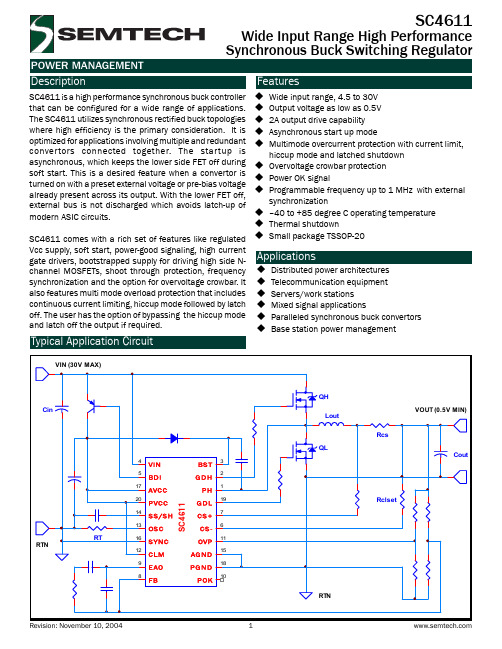
(1)
Symbol
Test Conditions
Min
Typ
Max
Unit
AVCC PVCC ISUPPLY IQUI
VIN > 5.5V VIN > 5.5V No load on GDH and GDL pins SS/SH = 0V
4.5 4.5
6 6 7 4
SC4611 comes with a rich set of features like regulated
Applications
Distributed power architectures Telecommunication equipment Servers/work stations Mixed signal applications Paralleled synchronous buck convertors Base station power management
Parameter BST to PGND VIN and BDI to PGND PVCC, AVCC to PGND PGND to AGND BST to PH GDH to PH, GDL to PGND All Other Pins to AGND GDH, GDL Source or Sink Current Storage Temperature Range Junction Temperature Lead Temperature (Soldering) 10 Sec.
Symbol VBSTMAX VINMAX AVCCMAX
Maximum 37 30 7 ±0.3 -0.3 to 7
赛米控丹佛斯电子 Board_93_GB_SKYPER_42_R 数据表

®Adaptor boardIGBT Driver CoreBoard 93 GB SKYPER 42 R Preliminary Data Features•Two output channels •Gold nickel finish •Failure managementTypical Applications*•Adaptor board for SKYPER 42 IGBT drivers in bridge circuits for industrial applications •PCB with gold plating •DC bus up to 1200VFootnotesIsolation test voltage with external high voltage diodeThe isolation test is not performed as a series test at SEMIKRONThe driver power can be expanded to 50µC with external boost capacitorsIsolation coordination in compliance with EN50178 PD2Operating temperature is real ambient temperature around the driver core Degree of protection: IP00This is an electrostatic discharge sensitive device (ESDS), international standard IEC 60747-1, Chapter IX* The specifications of our components may not be considered as an assurance of component characteristics. Components have to be tested for the respective application. Adjustments may be necessary. The use of SEMIKRON products in life support appliances and systems is subject to prior specification and written approval by SEMIKRON. We therefore strongly recommend prior consultation of our staff.Absolute Maximum Ratings SymbolConditionsValuesUnitV s Supply voltage primary 16V Iout PEAK Output peak current 30A Iout AVmax Output average current 150mA f max Max. switching frequency100kHz V CECollector emitter voltage sense across the IGBT1700V V isol IO Isolation test voltage input - output (AC, rms, 2s)4000V V isolPD Partial discharge extinction voltage, rms, Q PD ≤ 10pC1500V V isol12Isolation test voltage output 1 - output 2 (AC, rms, 2s)1500V R Gon min Minimum rating for external R Gon 0.8ΩR Goff min Minimum rating for external R Goff 0.8ΩT op Operating temperature -40...85°C T stgStorage temperature-40 (85)°CCharacteristics SymbolConditionsmin.typ.max.UnitV s Supply voltage primary side 14.41515.6V V i Input signal voltage on / off 15 / 0V V IT+Input treshold voltage HIGH 12.3V V IT-Input threshold voltage (LOW) 4.6V V G(on)Turn on output voltage 15V V G(off)Turn off output voltage-8V t d(on)IO Input-output turn-on propagation time 1.1µs t d(off)IOInput-output turn-on propagation time1.1µsAdaptor Board 93 SKYPER® 42 RTechnical ExplanationsRevision 04------------------------------------------------------------------------------------------------------------------------------------------------------------------------------------------ This Technical Explanation is valid for the following parts:Related documents:Prepared by: Johannes Krapp------------------------------------------------------------------------------------------------------------------------------------------------------------------------------------------ ContentApplication and Handling Instructions (2)Further application support (2)General Description (2)Dimensions (3)PIN Array (3)Setting Dynamic Short Circuit Protection (4)Collector Series Resistance (4)Adaptation Gate Resistors (5)Boost Capacitors (6)Environmental conditions (6)Mounting Notes (6)Please note:All values in this technical explanation are typical values. Typical values are the average values expected in large quantities and are provided for information purposes only. These values can and do vary in different applications. All operating parameters should be validated by user’s technical experts for each application.Application and Handling Instructions▪Please provide for static discharge protection during handling. As long as the hybrid driver is not completely assembled, the input terminals have to be short-circuited. Persons working with devices have to wear a grounded bracelet. Any synthetic floor coverings must not be statically chargeable. Even during transportation the input terminals have to be short-circuited using, for example, conductive rubber. Worktables have to be grounded. The same safety requirements apply to MOSFET- and IGBT-modules.▪Any parasitic inductances within the DC-link have to be minimised. Over-voltages may be absorbed by C- or RCD-snubber networks between main terminals for PLUS and MINUS of the power module.▪When first operating a newly developed circuit, SEMIKRON recommends to apply low collector voltage and load current in the beginning and to increase these values gradually, observing the turn-off behaviour of the free-wheeling diode and the turn-off voltage spikes generated across the IGBT. An oscillographic control will be necessary. Additionally, the case temperature of the module has to be monitored. When the circuit works correctly under rated operation conditions, short-circuit testing may be done, starting again with low collector voltage.▪It is important to feed any errors back to the control circuit and to switch off the device immediately in failure events.Repeated turn-on of the IGBT into a short circuit with a high frequency may destroy the device.▪The inputs of the hybrid driver are sensitive to over-voltage. Voltages higher than V S +0,3V or below -0,3V may destroy these inputs. Therefore, control signal over-voltages exceeding the above values have to be avoided.▪The connecting leads between hybrid driver and the power module should be as short as possible (max. 20cm), the driver leads should be twisted.Further application supportLatest information is available at . For design support please read the SEMIKRON Application Manual Power Modules available at .General DescriptionThe Board 93 GB SKYPER® 42 is an adaptor board for the IGBT module SKiM® 93 (spring contact). The board is paralleling three channels so the SKiM module can be used in half bridge configuration. The board can be customized allowing adaptation and optimization to the used IGBT module.The switching characteristic of the IGBT can be influenced through user settings, e.g. changing turn-on and turn-off speed by variation of R Gon and R Goff. Furthermore, it is possible to adjust the monitoring level and blanking time for the DSCP (see Technical Explanations SKYPER® 42 R).Please note:This technical explanation is based on the Technical Explanations for SKYPER®42 R. Please read the Technical Explanations SKYPER® 42 R before using the Adaptor Board.Dimensions116 PIN ArraySetting Dynamic Short Circuit ProtectionThe Vce formula for the Vce monitoring is described in the technical explanation of SKYPER 42 R. Collector Series ResistanceDesignation Shape SettingR105 MiniMELF (SMD) R VCE*Factory setting: not equippedTOPR205 MiniMELF (SMD) R VCE *Factory setting: not equippedBOTAdaptation Gate ResistorsBoost CapacitorsEnvironmental conditionsPlease refer to the technical explanation of SKYPER 42 R for the environmental conditions.Mounting NotesDISCLAIMERSEMIKRON reserves the right to make changes withoutfurnished in this document is believed to be accurate and reliable. However, no representation or warranty is given and no liability is assumed with respect to the accuracy or use of such information. SEMIKRON does not assume any liability arising out of the application or use of any product or circuit described herein. Furthermore,。
Protel Disgner
电子爱好者协会I C封装大全来源:志刚电子 作者:1、B G A(b a l l g r i d a r r a y)球形触点陈列,表面贴装型封装之一。
在印刷基板的背面按陈列方式制作出球形凸点用以代替引脚,在印刷基板的正面装配L S I芯片,然后用模压树脂或灌封方法进行密封。
也称为凸点陈列载体(P A C)。
引脚可超过200,是多引脚L S I用的一种封装。
封装本体也可做得比Q F P(四侧引脚扁平封装)小。
例如,引脚中心距为1.5m m的360引脚B G A仅为31m m见方;而引脚中心距为0.5m m的304引脚Q F P为40m m见方。
而且B G A不用担心Q F P 那样的引脚变形问题。
该封装是美国M o t o r o l a公司开发的,首先在便携式电话等设备中被采用,今后在美国有可能在个人计算机中普及。
最初,B G A的引脚(凸点)中心距为1.5m m,引脚数为225。
现在也有一些L S I厂家正在开发500引脚的B G A。
B G A的问题是回流焊后的外观检查。
现在尚不清楚是否有效的外观检查方法。
有的认为,由于焊接的中心距较大,连接可以看作是稳定的,只能通过功能检查来处理。
美国M o t o r o l a公司把用模压树脂密封的封装称为O M P A C,而把灌封方法密封的封装称为 G P A C(见O M P A C和G P A C)。
2、B Q F P(q u a d f l a t p a c k a g e w i t h b u m p e r)带缓冲垫的四侧引脚扁平封装。
Q F P封装之一,在封装本体的四个角设置突起(缓冲垫)以防止在运送过程中引脚发生弯曲变形。
美国半导体厂家主要在微处理器和A S I C等电路中采用此封装。
引脚中心距0.635m m,引脚数从84到196左右(见Q F P)。
3、碰焊P G A(b u t t j o i n t p i n g r i d a r r a y)表面贴装型P G A的别称(见表面贴装型P G A)。
LPS-RK_SPI双元素时延过流保护罐Relay说明书
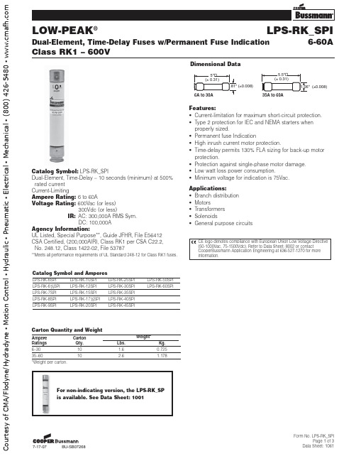
LPS-RK_SPI
Dual-Element, Time-Delay Fuses w/Permanent Fuse Indication
Class RK1 – 600V
6-60A
Time-Current Characteristic Curves–Average Melt
RMS SYMMETRICAL CURRENT IM AMPERES
1.06" (±0.008)
Catalog Symbol: LPS-RK_SPI Dual-Element, Time-Delay – 10 seconds (minimum) at 500%
rated current Current-Limiting Ampere Rating: 6 to 60A Voltage Rating: 600Vac (or less)
LPS-RK-9SPI
LPS-RK-20SPI
LPS-RK-45SPI
LPS-RK-50SPI LPS-RK-60SPI
Carton Quantity and Weight
Ampere Ratings 6–30 35–60 *Weight per carton.
Carton Qty. 10 10
Lbs. 1.6 2.6
Courtesy of CMA/Flodyne/Hydradyne ▪ Motion Control ▪ Hydraulic ▪ Pneumatic ▪ Electrical ▪ Mechanical ▪ (800) 426-5480 ▪
LOW-PEAK®
LPS-RK_SPI
7-Байду номын сангаас7-07
BU-SB07268
Form No. LPS-RK_SPI Page 3 of 3
Siplace pro培训教材
Siplace pro培训教材本培训资料包括xxxx等X部分一. 概述对于SIPLACE PRO线体线控机,线控机PRO使用MSDE小型数据库,PRO编程服务器是使用SQL中型数据库。
SIPLACE PRO线体线控机与PRO编程服务器PRO数据没有直接关联,生产线拷程序文件是通过在PRO编程服务器的终端电脑中将相应程序的JOB XML文件导出,再在本地通过网络将JOB XML文件导入到线控机本地。
对于PRO线控机电脑硬件推荐配置如下:Pentium4 2.4GHZ or higher20GB hard disk512MB memory软件需求如下:Windows 2000 Professional with SP4 and MSDE 2000 with SP3a,Or Windows XP Professional with SP1a and MSDE 2000 with SP3aMicrosoft .NET Framework 1.1(registered trademark)SiplacePro 支持的机器型号及软件最低版本:Siplace 80S20、80S23 407.XXS25HM S27HM HS50 502.XX / 503.XXHS50+ HS60 503.XX80F4 80F4/6 80F5 F5HM 407.XXHF HF3 504.XX /505.XXSiplace Pro不支持的机器型号: 80S15 80F3 G系列机型重新安装软件后标准库数据需要重新导入。
导入步骤:1.点击tool→import→line puter import wizard, 弹出对应的对话框;2.输入Masterdata 路径: C:\program file\simens siplace\siplace pro\stammdaten ;3.□Import Restrictions(约束条件)□ Import Feeder Quality Manager Data(飞达数量管理数据)□ Apply Feeder Assignment to ponent and ponent Shapes(飞达配置)□Preserve SipacePro Specific data on overwriting,Only applies to ponentand ponentshapes。