AFG-2005
阻抗匹配问题
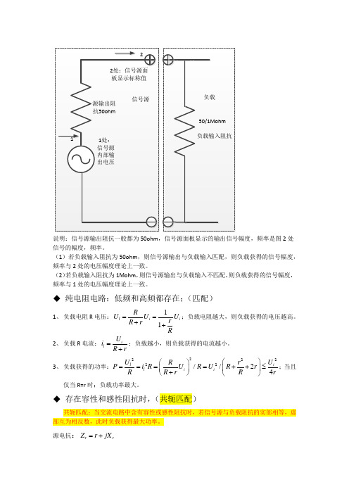
说明:信号源输出阻抗一般都为50ohm ,信号源面板显示的输出信号幅度,频率是图2处信号的幅度,频率。
(1)若负载输入阻抗为50ohm ,则信号源输出与负载输入匹配,则负载获得的信号幅度,频率与2处的电压幅度理论上一致。
(2)若负载输入阻抗为1Mohm ,则信号源输出与负载输入不匹配,则负载获得的信号幅度,频率与1处的电压幅度理论上一致。
◆ 纯电阻电路:低频和高频都存在;(匹配)1、 负载电阻R 电压:11l i i R U U U r R r R==++;负载电阻越大,则负载获得的电压越高。
2、 负载R 电流:il U i R r=+;负载越小,则负载获得的电流越小。
3、 负载获得的功率:222222//24l i l i i U U R r P i R U R U R r R R r R r ⎛⎫⎛⎫====++≤ ⎪ ⎪+⎝⎭⎝⎭;当且仅当R=r 时;负载功率最大。
◆ 存在容性和感性阻抗时,(共轭匹配)共轭匹配:当交流电路中含有容性或感性阻抗时,若信号源与负载阻抗的实部相等,虚部互为相反数,此时负载获得最大功率。
源电抗:r r Z r jX =+负载电抗:R R Z R jX =+ 负载功率:()()()()()()222222222142R r R r R r R r U RU U U P r R r X X R r X X r X X R r X X R R R R===≤⎛⎫+++⎡⎤+++++++++ ⎪⎣⎦⎝⎭ 当且仅当R rR rX X =⎧⎨=-⎩时,负载获得最大功率。
结论:1、需要大的电流输出,则选择小的负载R ;2、需要大的电压输出,则选择大的负载R ;3、需要输出最大功率,则选择与信号源内阻匹配的电阻R 。
(功率传递!)低频时,信号的波长相对与传输线来说很长,传输线可以看成短线,反射可以不考虑。
高频时,f c λ=;信号频率很高时,信号的波长就很短,当波长和传输线的长度可以比拟时,反射信号叠加在原来信号上将会改变原信号的形状。
美标A系列对应标准

普通型,带槽和防护型碳素工字钢轨
A3-01(2006)
Carbon (Non-Heat-Treated) Standard Specification for General Requirements for Rolled
低、中、高碳素钢鱼尾(连接)板
A6/A6M-05a
Structural Steel Bars, Plates, Shapes, and Sheet Piling Standard Specification for General Requirements for Steel Plates
标准号 A1-00(2005)
Hale Waihona Puke 英文名称 Standard Specification for Carbon Steel Tee Rails Standard Specification for Carbon Steel Girder Rails of Plain,
中文名称 碳素钢丁字轨
A2-02
Grooved, and Guard Types Standard Specification for Steel Joint Bars, Low, Medium, and High
Steel Plate, Sheet, and Strip Standard Specification for Electric-Resistance-Welded Carbon
不锈钢和耐热铬钢板、薄板及带材 电阻焊接碳素钢钢管及碳锰钢锅炉和过热器管的技
A178/A178M-02
Steel and Carbon-Manganese Steel Boiler and Superheater Tubes 术规范 Standard Specification for Seamless Cold-Drawn Low-Carbon Steel
激光制导武器
情报交流本文2006-02-20收到,赵江和徐世录分别系东北电子技术研究所高级工程师和工程师,徐锦系辽宁对外经贸学院本科生激光制导武器赵 江 徐 锦 徐世录摘 要 论述了激光制导武器的原理、特点及制导方式,并简要地介绍了几种激光制导导弹、制导炸弹、制导炮弹的应用与发展趋势。
关键词 激光制导 导弹炸弹 炮弹引 言激光制导是一种先进的制导技术,主要优点是命中率高,在历次现代化战争中发挥了重要的作用。
在第一次海湾战争中,以美国为首的多国部队使用了新一代微型计算机和激光制导系统,使炸弹和导弹的命中率达到了几乎难以置信的程度。
在第二次海湾战争中,美英部队运用激光制导加上GPS 辅助导航定位系统,使得制导导弹、制导炸弹、制导炮弹的命中率几乎达到100%。
1 激光制导[1]激光制导就是以激光为信息载体,把导弹、炮弹或炸弹引向目标而实施精确打击的先进技术。
精准是激光制导武器的鲜明特点,由于激光的单色性好,光束的发散角小,敌方很难对制导系统实施有效干扰,因而使它具有其它制导方式无法匹敌的优势。
所以,当激光制导武器攻击固定或活动目标时,就像长了眼睛一样,命中率极高。
激光制导武器甚至可以从通气孔进入,炸毁地下目标,令对方防不胜防。
而激光制导与红外、雷达、GPS 等实现复合制导,则更有利于提高制导精度和应付各种复杂的战场环境,从而发挥全天候作战的优势。
1.1 原理激光制导的基本原理是:用激光器发射激光束照射目标,装于弹体上的激光接收装置接收照射的激光信号或目标反射的激光信号,算出弹体偏离照射或反射激光束的程度,不断调整飞行轨迹,使战斗部沿着照射或反射激光前进,最终命中目标。
1.2 制导方式激光制导方式有半主动寻的式、主动寻的式和波束式(驾束式)三种。
目前激光制导武器中大都采用半主动激光制导方式,即导引头与激光照射装置分开配置于两地,前者随弹飞行,后者置于弹外。
激光照射器用来指示目标,故又称激光目标指示器。
导引头通过接收目标反射的激光或直接接收照射激光,引导导弹飞向目标。
NOFO 2005
NOFO STANDARDforOIL RECOVERY VESSELS2005Issued: July 1985Rev 01: March 2000Rev 02: August 2003Rev 03: December 2004Rev 04: August 2005NOFO (Norwgian Clean Seas Association for Operating Companies)P.O. Box 8077, N-4068 StavangerBesøksadr.: Vassbotnen 1, Trallfa gården, 4313 SandnesTel: (47) 51 84 65 60 - Fax: (47) 51 56 23 98E-mail: post@nofo.no - Org.nr. 971 454 075 – Internett: www.nofo.noLIST OF CONTENTS1INTRODUCTION (3)1.1 Requirements (3)1.2 Deviation from requirements (3)2VESSELS (3)2.1 Collecting tanks (3)2.1.1 Tank capacity (3)2.1.2 System for heating recovered oil (3)2.1.3 Access and inspection (4)2.1.4 Ventilation (4)2.2 Loading and discharge systems (4)2.2.1 Discharge system (4)2.2.2 Discharge capacity (4)2.2.3 Choice of pumps (5)2.2.4 Discharge / loading manifold on deck (5)2.2.5 Valves (5)2.2.6 Filter system (drawing no. 009) (5)2.3 Deck layout (drawing no. 001 – 009) (5)2.3.1 Transverse rail astern (drawing no. 004) (5)2.3.2 Oil recovery equipment anchoring points (6)2.3.3 Positioning the skimmer (6)2.3.4 Stern gate (6)2.3.5 Mobilization time requirement (6)2.4 Towing boom system (drawing no. 001) (6)2.5 Cabin capacity (7)3OIL RECOVERY EQUIPMENT (7)3.1 Electric power supply (7)3.2 Air for power tools (7)3.3 Water supply (7)3.4 Hydraulic power (drawing no. 002 and no. 010) (7)3.4.1 Hydraulic power outlet (7)3.4.2 Capacity (7)3.4.3. Hydraulic couplings (8)4MISCELLANEOUS (8)4.1 Log (8)4.2 Pilothouse – cable duct (8)4.3 Current meter (8)5APPROVAL (8)5.1 Design drawings (8)5.2 Inspection (9)5.3 Capacity tests (9)5.4 Certificates (9)Attachment 1Drawings_NOFO-std_20051 INTRODUCTION1.1 RequirementsThis document specifies the requirements, which vessels included in NOFO’s standby fleet must meet. It is also assumed that the vessels satisfy the requirements set by the Norwegian authorities and classification societies.1.2 Deviation from requirementsNOFO may accept deviations from certain sub-requirements in cases where this isconsidered not to significantly detract from the suitability of the vessels in ORO (OilRecovery Operation). All deviations from the requirements must be clarified withNOFO in the design phase.2 VESSELS2.1 Collecting tanks2.1.1Tank capacityThe tank capacity in ORO shall be able to use the following tanks:•Mud tanks•Brine tanks•Base oil tanks•Methanol tank•Special product tanks•Staff tanks•Chain boxes•Fuel tanksIt will only be possible to omit certain tanks if these are clearly unsuitable. This must be clarified with NOFO in the design phase by submitting the tank plan for approval.The following tanks is not to be included in ORO’s tank capacity:•Wing tanks, bottom tanks and other tanks with an inner structure•Freshwater tanks•Tanks with a volume of less than 50 m3Under no circumstances must the tank capacity for storage of recovered oil be less than 1,000 m³. An active effort must be made to achieve the greatest possible tank capacity.2.1.2System for heating recovered oilAll the vessel’s ORO tanks must be equipped with a permanent system for heatingrecovered oil / emulsion. This system must ensure that it is possible to raise thetemperature of a volume of 1,000 m3 with 15 °C within 12 hours; calculated for a seatemperature of 5 °C and air temperature of 0 °C. The heating elements for each tankmust be dimensioned so that the whole heating capacity may be used if heating nomore than 2 - 3 tanks at the same time.2.1.3 Access and inspectionIt must be possible to access all ORO tanks from the deck via manholes with standard dimension: 600 x 800mm.All ORO tanks, with the exception of methanol tanks, must be equipped with an ullage hatch to ease inspection and sounding.2.1.4 VentilationAs specified in the requirements from the classification authorities, tank ventilation must be permanently installed.2.2Loading and discharge systems2.2.1 Discharge systemThe vessel must have a separate (dedicated) pump and pipe system for use in ORO.Each tank must be equipped with a dedicated discharge pump. The pump can besubmerged in the tank or connected to the tank via a short suction tube. The samepump may serve two adjacent tanks. The pump system on the suction side of eachtank, must not cause a drop in pressure of more than 0.5 bar when discharging oil witha viscosity of 3000 cSt.The pipe system must enable circulation of the volume in individual tanks without interrupting loading / discharging of other tanks.For preparation of the ORO pipe system, all orifices to be closed / opened must be Seut type or a similar approved type of valve.2.2.2Discharge capacityThe vessel’s discharge system (pumps / pipe system) must satisfy the following total delivery capacity requirements for withdrawal on deckMin 500 m³/hour against 3 bar at 3,000 cSt viscosity andMin 300 m³/hour against 7 bar at 3,000 cSt viscosity,Theoretical calculations, which take pressure loss in the pipe system at deck level into account and are based on the documented capacities of the pumps, shall substantiate the discharge capacity. It shall be possible to achieve the discharge rate when discharging no more than half of the tanks at the same time.It shall be possible to demonstrate discharge capacity through physical tests.2.2.3Choice of pumpsThe pumps used must be screw pumps or another type of pump with documented suitability for oils / emulsions. The capacity of each pump must be adequate to meet the total discharge capacity requirement when discharging no more than half of the tanks at the same time. No single pump must have a capacity less than 100 m3.NPSH must be at least 0.5 bar for pumps that are not submerged in the tanks. All capacity numbers for pumps must be documented up to minimum 3.000 cSt.2.2.4Discharge / loading manifold on deckThe loading and discharge pipes to / from the tanks must be connected to a manifold approx. 15 m from the vessel’s stern on the starboard side. The manifold must be positioned so that the connected hoses do not have sharp bends and are not exposed to wear against the vessel’s other installations.The manifold and pipe system must allow for loading at the same time as settled seawater is pumped overboard. The vessels must have a pipe system on board to carry settled seawater over the side of the vessel and into the sea on the starboard side.The connections shall be of type:6" Weco union female coupling, wp 1000/69 psi/bar.2.2.5ValvesIt must be possible to switch between the tanks during loading / discharging preferably by using remotely operated valves.2.2.6Filter system (drawing no. 009)The vessel’s loading line must be equipped with a double filter system to prevent debris / waste from being pumped into the tanks. The dimensions of the filter must be tailored to the tolerance of the vessel’s discharge pumps in order to minimize the chance of damage / shutdown. The filter housing should be equipped with a quick-opening lock to enable quick cleaning of the filter.2.3 Deck layout (drawing no. 001 – 009)2.3.1Transverse rail astern (drawing no. 004)On vessels that have a transverse rail astern, this must be removable and give an opening with a minimum width of 7.0 m and height of 2.5 m for launching / recovery of oil booms over the stern. The transition between the stern / deck and any remaining rail must be rounded with a minimum radius of 250 mm.2.3.2Oil recovery equipment anchoring pointsThe vessels must have permanent anchoring points for oil recovery equipment. When positioning oil recovery equipment, there must be at least a gap of 400 mm between the vessel’s installations and the revolving oil skimmer and booms (refer to drawings 002 and 004). If container anchoring points on the deck are exposed to knocks and external strain, these should be covered when not in use.2.3.3Positioning the skimmerThe rail astern on the starboard side, and possible the stern itself must not be of a height or have a cover that obstructs the oil skimmer operator’s view. If the rail is higher than 2.5 m, a platform must be built on which the oil skimmer is positioned and can be operated. The platform must be built around the whole of the oil skimmer so that the operator may work with the equipment from all sides. The platform must also be permanently installed. If the platform hampers the regular use of the vessel, a platform that can be lowered or a hinged arrangement, may be accepted.The platform must be designed with oil spills drainage (for example by using a grating). If the base is higher than 1 m above the main deck, there must be a railing around the platform. The base must be designed and classified in accordance with the forces in action when the oil recovery equipment is operated (ref. drawing nos. 003, 006 and 007)2.3.4Stern gateThe stern gate must be hinged, and it must be possible to open, close and secure ithydraulically. Attachment using screw bolts must be avoided.2.3.5Mobilization time requirementThe total time for preparing the deck area for receiving the oil recovery equipment on board must not exceed 1 hour. The vessel’s crew must be able to carry out this work.2.4 Towing boom system (drawing no. 001)The vessel’s tugger winch on the starboard side is used for handling the towropes abeam.The vessel must have an anchoring point on the starboard side, approx. 30 m from the stern for controlling the towrope abeam. The anchoring point must be positioned so that there is no wear on the wire during operation of the towropes.Towrope tension: 15 tonnesWire length: 110 m2.5 Cabin capacityThe vessel must have at least 10 berths for NOFO’s ORO personnel.3 OIL RECOVERY EQUIPMENTOperation of NOFO’s oil recovery equipment requires the following supply from the vessel:3.1 Electric power supplyPower supply outlets for the oil recovery equipment must be installed in a cabinet with air tightness class IP 66 or better. The cabinet should be made from rustproof material and be located in the protected area at the rear of the deckhouse. The cabinet must be marked with ”NOFO” and must contain the following outlets:3 pcs CEAG outlet 1 - phase 16A/230v Eex-ed (Blue) - GHG 5113306 R 00011 pc CEAG outlet 3 - phase 32A/380/415 Eex-ed (Red)- GHG 5124406 R 0001 3.2 Air for power toolsThe air outlet for power tools / equipment must be located in areas where such tools may be used in connection with mobilization / demobilization of oil recovery equipment on board.3.3 Water supplyThe water supply for jet water washing must be located at the rear of the deckhouse.The water supply must have the following capacity and connections:1'' claw coupling, European standardWater capacity: min. 1500 l/hour3.4 Hydraulic power (drawing no. 002 and no. 010)3.4.1 Hydraulic power outletHydraulic power outlets from the vessel’s system: 2 pcs. high pressure, 2 pcs. return and 2 pcs. drainage, must be located on the starboard side, approx. 10 m from the vessel’s stern post.3.4.2 CapacityFor operation of the oil recovery equipment, the following two alternatives for outlets on deck must be satisfied:295 litres per minute at 280 bar390 litres per minute at 240 barIf the same power source operates the vessel’s discharge pumps, 50% of the discharge pumps’ total power requirements will be in addition to what has been mentioned above.3.4.3. Hydraulic couplingsAll hydraulic couplings on board must be acid-proof female couplings.The high-pressure pipeline must have a shut-off valve, and branch into two outlets with the following 11/4'' couplings:Snap Tite S71-3C16-20RP with ”sleeve lock”The return pipeline must branch into two outlets with the following 1½'' couplings: Tema - Flat face FF10010 - 150 RVThe drainage pipeline must branch into two outlets with the following ½'' couplings: Tema 5010 RV4 MISCELLANEOUS4.1 LogThe vessel must be equipped with a log to measure the relative speed through the water.4.2 Pilothouse – cable ductThe pilothouse must be prepared for a cable duct from the external down-link antenna.4.3 Current meterThe vessel must be equipped with a current meter.5 APPROVAL5.1 Design drawingsThe following drawings must be sent electronically (AutoCad) and as a hardcopy (one copy) to NOFO for approval:Tank PlanOil recovery system, Piping diagramMain deck arr. for Oil Recovery equipmentHydraulic piping diagramStern gateDrawings or appendices must contain the following information:The number and size of ORO tanksHydraulic pump capacitiesORO pump capacity, pressure and NPSHCapacity calculations for the discharge system, including calculation of pressure loss in the pipe systemOrifices and valve arrangement in the ORO systemDeck anchoring points for NOFO equipmentLocation of couplings for hydraulic, loading / discharge lines and electrical outlets.Design of any deck layout that requires time when preparing for mobilization (stern gate, oil skimmer base, etc).5.2 InspectionA NOFO representative will inspect the vessel once it is ready for operation.5.3 Capacity testsBefore final approval as an ”Oil Recovery Vessel according to NOFO standard”, the vessel must be inspected at one of NOFO’s spill contingency bases and capacity tests will be conducted on hydraulic and discharge pumps.In some cases, it will be possible to conduct tests by discharging oil / emulsion.During such tests, the vessel must be able to demonstrate and meet the discharge capacity requirements specified in this standard.5.4 CertificatesThe certificate is issued to the ship owner and is valid for three years or as long as the vessel is part of NOFO’s standby fleet. Vessels, which have been out of the NOFO standby fleet for more than three years must be reinspected and re-approved before they can be used in NOFO’s standby fleet.Attachment 1NOFO STANDARDforOIL RECOVERY VESSELSDRAWINGS。
AWG2005 数据手册(英文)
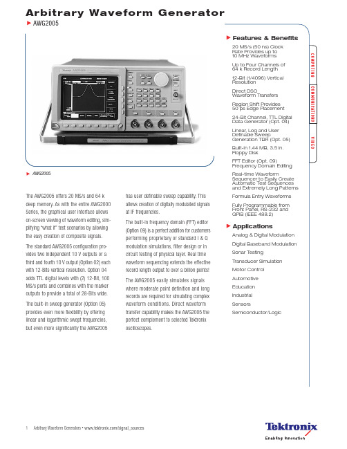
Arbitrary Waveform Generator•/signal_sources1•/signal_sources2Arbitrary Waveform GeneratorAWG2005CharacteristicsStandard WaveshapesSine,square,triangle,ramp,noise,arbitrary,linked sequence,and DC.Arbitrary WaveformsExecution Memory – Waveform:64 k (65,535) for each channel.Marker:64 k for each channel.Waveform Size:16 to 64 k in multiples of 16.Real-time Sequence Memory – 8 k individual waveforms.Loop Counter –Waveform:1 to 64 k repeats.Sequence:1 to 64 k repeats.Catalog Memory – 2 MB.Catalog Memory ClockFrequency Range – 0.01Hz to 20MHz.Resolution – Standard:4 digits.With Option 05:7 digits.Accuracy –Standard:50ppm (+15 ºC to +30 ºC).Option 05:5 ppm (+15 ºC to +30 ºC).Operating ModesContinuous – Output waveform/sequence continuous at programmed parameters.Triggered – Output quiescent until triggered by an external,GPIB,or manual trigger; generates a waveform/sequence only one time.Gated – Same as continuous mode except period is executed only for the duration of the gated signal until the sequence is completed.Seq/Wfm Advance –Continuous:Continuously outputs thewaveform/sequence in the Sequence file.The next trigger advances to the next waveform/sequence.Master/Slave Operation.Step – Output quiescent until triggered; then exe-cute the next waveform/sequence in the Sequence file.When the loop count reaches its value,output stops and waits for next trigger.Auto Step –Continuous:Continuously outputs thewaveform/sequence in the Auto Step file.Step:Output quiescent until triggered.Master – Provides Point Rate Clock and Trigger to a slave arbitrary waveform generator for phase synchronous parallel operation.Slave – Receives Clock and Trigger from a system clock for parallel operation.Main OutputDigital-to-Analog Resolution – 12 Bits.Output Impedance – 50Ω.Amplitude (1MHz Clock,000 and FFF Waveform Data,Norm,No Filter,No Offset,Excluding and ADD Operation)–Range:0.05V to 10V p-p into 50Ω.Resolution:1mV (4 digits).DC Accuracy:0.050V to 0.999V,±(0.5% of amplitude + 5mV); 1.000V to 10.000V,±(1% of amplitude + 50mV).Offset –Range:–5.0V to +5.0V into 50Ω(–200mA to +200mA).Resolution:5mV (4 digits).Accuracy (1MHz clock,7FF waveform data,norm,no filter,amplitude range 0.05V):– ±(1% of offset + 10mV).Pulse Response (20MHz clock,000 and FFF waveform data,norm,no filter,amplitude 5V,no offset)–Rise/Fall Time:<35ns.Flatness:Within ±3% after 150ns from rise/fall edges.Aberrations:Within ±7%.Cross Talk Between Channels – 512-point sine,20MHz clock,norm,no filter,amplitude offset.<70dBc.Noise Floor –20MHz clock,7FFF waveform data,norm,no filter,no offset.0.5V:≤110dBm/Hz at 1MHz.5.0V:≤95dBm/Hz at 1MHz.Sinewave Characteristics – Function Generator mode,100Hz to 200kHz,no offset.Flatness(1V amplitude,1kHz reference):Within –4%.T.H.D.(Including up to 4th harmonics):≤55dBc at 5.0V.Auxiliary OutputsMarker –Amplitude:>2V into 50Ω.Impedance:50Ω.Marker to signal delay:35ns.Clock –Amplitude:>2V into 50Ω.Impedance:50Ω.Control Sig.–Amplitude:>2V into 50Ω.Impedance:50Ω.Sweep (Opt. 05)–Waveshape:Same waveshape as selected sweep.Amplitude:0 to 5V (amplitude is dependent upon start and stop frequencies with a 5V maximum limit).Impedance:600Ω.Digital Data Out (Opt. 04 eliminates RS-232interface)–Output signals (CH 1 and CH 2):D0 to D11,Clock.Level:TTL.Amplitude:2V into 50Ω.Skew between data:Within ±10ns.Clock to data delay:Within ±10ns.Impedance:50Ω.Arbitrary Waveform GeneratorAWG2005 Auxiliary InputsTrigger–Threshold Level:–5V to +5V.Resolution:0.1V.Accuracy:±(5% of Level + 0.1V).Minimum Pulse Width:150ns.Minimum Input Swing:0.2Vp-p.Maximum Input Volts:±10V (DC + peak AC).Impedance:10 kΩ.Trigger to Signal Delay:Internal Clock,400ns(excluding clock sweep mode).AM (512-point Sine,20MHz Clock,AM,No Filter,5V Amplitude,No Offset)–Range:2Vp-p(–1V to +1V) for 100% modulation.Amplitude Accuracy:Within 5%.Maximum Input Volts:–5V (DC + peak AC).Impedance:10 kΩ.ADD (512-point Sine,20MHz Clock,Add,NoFilter,5V Amplitude,No Offset)–Range:10Vp-p(–5V to +5V).Amplitude Accuracy:Amplitude specificationplus 5%.Maximum Input Volts:–5V (DC + peak AC).Impedance:50Ω.Control Sig.–Threshold Level:TTL level (0.8V to 2.0V).Minimum Pulse Width:40ns.Maximum Input Volts:5V to 0V.Impedance:10 kΩ.Clock–Threshold Level:TTL level (0.8V to 2.0V).Minimum Pulse Width:20ns.Maximum Input Volts:5V to 0V.Impedance:External Clock,330Ω; Slave Mode,10 kΩ.Frequency Range:1Hz to 20MHz.Sweep (Opt. 05 only)–Type:Linear,log,arbitrary.Mode:Continuous,triggered,gated.Update Rate:1 s to 65,535 ms.Points per Sweep:8 K maximum.Function GeneratorWaveform Shape– (Predefined 100 pt.waveforms).Sine,Triangle,Square,Ramp,Pulse (1MHz filter isinserted when Sine is selected).Frequency– 1.000Hz to 200kHz.Duty Cycle– 0% to 100%,Pulse only.Programmable InterfaceGPIB– IEEE 488.2-1987 compatible.RS-232– 9-Pin D connector.See Mixed Signal Sources Intro for EnvironmentalCharacteristics.Ordering InformationAWG2005Programmable Arbitrary Waveform Generator.Includes:User/Programmer’s Manual070-8958-05/070-8657-05,GPIB ProgrammingExamples Disk,Sample Waveform Library Disk,Cal.Certificate,Power Cord.Please specify power plug and manual versionwhen ordering.Recommended AccessoriesAccessory Pouch –Order 016-1159-00.Front Cover –Order 200-3232-01.RS-232-C Cable –9-Pin to 25-Pin.Order174-1453-00.Service Manual –Order 070-8962-07.Rackmount Kit –Order 040-1444-00.GPIB Cable –Order 012-0991-00.50ΩBNC Cable –Order 012-1342-00.12-Bit Word Generator Cable (Opt. 04) –Order174-3192-00.SMA to BNC Adapter –Order 015-0554-00.50ΩTermination –Order 011-0049-02.OptionsOpt. 02 –Add Two Channels (Four Total).Opt. 04 –24-Bit,TTL Digital Data Out*1,*2.Opt. 05 –Add Clock Sweep.Opt. 09 –Add FFT Editor.Allows editing waveformsin the frequency domain*1.Opt. 1R –Rackmount.Floppy Drive AccessMoved to Front.Opt. B1 –Service Manual.Opt. L0 –English Manual.Power Plug OptionsOpt. A0 –North America Power.Opt. A1 –Universal EURO Power.Opt. A2 –United Kingdom Power.Opt. A3 –Australia Power.Opt. A4 –240 V,North America Power.Opt. A5 –Switzerland Power.ServiceOpt. C3 –Calibration Service 3 Years.Opt. C5 –Calibration Service 5 Years.Opt. D1 –Calibration Data Report.Opt. D3 –Calibration Data Report 3 Years(with Option C3).Opt. D5 –Calibration Data Report 5 Years(with Option C5).Opt. R3 –Repair Service 3 Years.Opt. R5 –Repair Service 5 Years.WarrantyOne year parts and labor.*1Options 04 and 09 are mutually exclusive.*2Option 04 eliminates RS-232 interface.Arbitrary Waveform Generators •3Arbitrary Waveform GeneratorAWG2005Arbitrary Waveform Generators •/signal_sources4Contact Tektronix:ASEAN / Australasia / Pakistan (65) 6356 3900Austria +43 2236 8092 262Belgium+32 (2) 715 89 70Brazil & South America55 (11) 3741-8360Canada1 (800) 661-5625Central Europe & Greece+43 2236 8092 301Denmark+45 44 850 700Finland+358 (9) 4783 400France & North Africa+33 (0) 1 69 86 80 34Germany +49 (221) 94 77 400Hong Kong(852) 2585-6688India(91) 80-2275577Italy+39 (02) 25086 1Japan81 (3) 3448-3010Mexico,Central America & Caribbean52 (55) 56666-333The Netherlands+31 (0) 23 569 5555Norway+47 22 07 07 00People’s Republic of China86 (10) 6235 1230Poland+48 (0) 22 521 53 40Republic of Korea82 (2) 528-5299Russia,CIS& The Baltics+358 (9) 4783 400South Africa+27 11 254 8360Spain +34 (91) 372 6055Sweden+46 8 477 6503/4Taiwan886 (2) 2722-9622United Kingdom & Eire+44 (0) 1344 392400USA1 (800) 426-2200USA(Export Sales) 1 (503) 627-1916For other areas contact Tektronix,Inc.at:1 (503) 627-7111Updated 20 September 2002Our most up-to-date product information is available at:Copyright © 2003,Tektronix,Inc.All rights reserved.Tektronix products are coveredby U.S.and foreign patents,issued and rmation in this publicationsupersedes that in all previously published material.Specification and price changeprivileges reserved.TEKTRONIX and TEK are registered trademarks of Tektronix,Inc.All other trade names referenced are the service marks,trademarks or regis-tered trademarks of their respective companies.05/03 HB/SFI 76W-10020-2The planning,design/development and manu-facture of electronic Test and Measurement instruments.。
SAEJ200-2005中文橡胶材料分类系统
2.引用标准
2.1可适用出版物——以下出版物在此处所指定的范畴内构成了本规程的一部分。
2.1.1 ASTM出版物——可从ASTM得到,地址:Barr Harbor大街100号,West Conshohocken, PA 1919428-2959。
表3——后缀字母的含意
后缀字母
要求的试验
A
耐加热老化性能
B
压缩永久变形
C
耐臭氧或耐天候性能
D
耐压缩—屈挠性能
EA
耐液体性能(水性的)
EF
耐液体性能(燃料)
EO
耐液体性能(油及润滑剂)
F
耐低温性能
G
耐撕裂性能
H
耐屈挠性能
J
耐磨性能
K
粘着
M
耐燃性能
N
耐冲击性能
P
耐着色性能
R
回弹性能
Z
任何应详细指定的专门技术要求
注3——当橡胶制品用于某些目的,而其中技术要求过于专门以至于无法由该分类系统完全地加以规定时,采购方有必要事先向供货方进行咨询,以确定适当的特性、试验方法以及试验限度技术规范。
1.1目的
1.1.1该文件的目的是为工程师在选择有用的、市场上可得到的橡胶材料时提供指导,同时进一步提供了一种方法,通过利用简单的命名标识对这些材料加以指定。
ASTM D 395——橡胶特性试验方法—压缩试验
ASTM D 412——橡胶拉伸特性试验方法
ASTM D 429——橡胶特性试验方法—刚性衬层粘着
焊材复验标准2005-1-26

焊接材料入厂检验程序规定1.主题内容与适用范围本程序规定了焊接材料复验的准则、验收标准、试验程序等内容。
本程序适用于我公司所有入厂的焊接材料。
2.引用标准GB/T983-1995《不锈钢焊条》GB/T5117-1995 《碳钢焊条》GB/T5118-1995 《低合金钢焊条》GB/T8110-1995 《气体保护电弧焊用碳钢、低合金钢焊丝》GB/T14957-94 《熔化焊用焊丝》GB/T14958-94 《气体保护焊用焊丝》YB/T5092-1996 《焊接用不锈钢丝》JB/T4747-2002 《压力容器用钢焊条定货技术条件》AWS A 5.4-92 《不锈钢手工电弧焊焊条》AWS A5.9-93 《不锈钢焊丝及填充丝》AWS A5.11-97 《镍和镍合金手工电弧焊条》AWS A5.14-97 《镍和镍合金裸填充丝及焊丝》AWS A5.22-95 《弧焊用不锈钢药芯焊丝和钨极气体保护焊用不锈钢药芯焊丝》《日本油脂公司不锈钢钨极氩弧焊焊丝》QG/FJ07.002-2004 《压力容器焊接管理标准》《抚顺机械设备制造有限公司焊接材料技术协议汇编》(2006版)3.名词解释:例检:对某一品牌焊接材料,只验证质保单、外观,及焊条的焊接工艺性,而不进行理化试验的检验程序。
4.复验准则4.1 入厂的焊接材料应按工号交检入库并委托复验,多个工号共用的焊材,按技术要求高的交检。
4.2用于三类产品压力容器受压元件焊接的焊接材料必须复验。
执行例检的除外。
4.3 用户在设备制造技术条件中规定或有正式要求的必须复验。
4.4 对于新供货商提供的首批焊接材料必须复验。
4.5对已执行例检的焊接材料,每年首批供货时,需要复验,如果合格继续例检;不合格,则取消该牌号焊接材料例检资格,需重新执行复验程序。
4.6使用单位对某种焊材质量提出疑义,或焊缝质量有下降趋势,由使用单位提出, 焊接负责人根据反馈意见确定对该种焊材是重新进行复验。
物理实验培训——示波器的原理与使用讲解

示波器的自检
校准信号 Up-p=2V、f=1kHz、T=1.00ms 用示波器测出该“标准信号”的峰-峰值Up-p与周期T,
与标准值进行比较,结果记入下表。
理论值
示波器 测量
峰—峰值 U p p 2V 衰减开关V DIV 档位
U p p 占垂直格数 峰峰值 U p p
校验结论
频率 f 1kHz 扫描速率TIME/DIV 档位
实验仪器:
YB4320 双踪示波器
AFG-2005 信号发生器
TH1912数字式交流毫伏 表
YB4320F型双踪四迹示波器面板
YB4320F型双踪四迹示波器面板
示波器面板控制件的作用简介
校准信号:示 波器自带的标
准信号源
荧光屏
辉度:轨迹 聚焦:轨迹 亮度调节 清晰度调节
电源开关
VOLTS/DIV: 调节衰减开关, 指示垂直方向 每格的偏转电 压值
垂直位移
垂直选择
水平位移
使用时都按下
内同步两 者必须保
持一致
接地: 输入零信号
被测信号耦合方式AC/ DC :交流/直流输入
微调旋钮 CH1:被测信号输入端口
TIME/DIV:调节扫 描速率,指示水平方 向每格的扫描时间
显示屏
频率电压调 波形选择 频率调节 电压调节 节键盘旋钮
功能键
单位按钮
输出开关 主输出端 电源开关
信号频率 f kHz
E f f0 100% f0
200Hz
1500Hz
ቤተ መጻሕፍቲ ባይዱ5KHz
人有了知识,就会具备各种分析能力, 明辨是非的能力。 所以我们要勤恳读书,广泛阅读, 古人说“书中自有黄金屋。 ”通过阅读科技书籍,我们能丰富知识, 培养逻辑思维能力; 通过阅读文学作品,我们能提高文学鉴赏水平, 培养文学情趣; 通过阅读报刊,我们能增长见识,扩大自己的知识面。 有许多书籍还能培养我们的道德情操, 给我们巨大的精神力量, 鼓舞我们前进。
2005[1].747.EC 中英文
![2005[1].747.EC 中英文](https://img.taocdn.com/s3/m/78a23189680203d8ce2f2440.png)
COMMISSION DECISIONof 21 October 2005amending for the purposes of adapting to technical progress the Annex to Directive 2002/95/EC of the European Parliament and of the Council on the restriction of the use of certain hazardous substances in electrical and electronic equipment(notified under document number C(2005) 4054)(Text with EEA relevance)(2005/747/EC)欧盟委员会于2005年10月21日为了适应技术发展,针对指令2002/95/EC附录关于欧盟议会和欧盟理事会在电气电子设备中限制使用某些有害物质进行修改的决定。
THE COMMISSION OF THE EUROPEAN COMMUNITIES, Having regard to the Treaty establishing the European Community, Having regard to Directive 2002/95/EC of the European Parliament and of the Council of 27 January 2003 on the restriction of the use of certain hazardous substances in electrical and electronic equipment (1), and in particular Article 5(1)(b) thereof, Whereas:欧洲共同体委员会,注意到成立欧洲共同体的条约,注意到欧洲议会和欧盟理事会2003年1月27日第2002/95/EC 号关于在电气电子设备(1)中限制使用某些有害物质指令,特别是其中第5(1)(b)条,鉴于:(1) In accordance with Directive 2002/95/EC the Commission is required to evaluate certain hazardous substances prohibited pursuant to Article 4(1) of that Directive.(1)遵照第2002/95/EC号指令,欧盟委员会需要对指令第4(1)条所禁令的某些有害物质进行评估。
如何有效处理并降低饲料原料中霉菌毒素的水平?

如何有效处理并降低饲料原料中霉菌毒素的水平?每年都有大量的粮食作物遭受霉菌污染,并且大部分会流向饲料行业,如作为常规饲料原料的玉米和小麦。
而一些加工副产品中的霉菌毒素更高,其中有些副产品也会输出到饲料行业,如玉米酒精粕、杂粕、糟渣等经常被用作非常规原料。
由此造成饲料中霉菌毒素超标。
若动物采食霉菌污染的饲料,将对其生长、生产、繁殖性能和抗病能力都造成负面影响,严重的还会导致损伤甚至死亡。
霉菌毒素的污染防控通常可以在三个层次进行。
首先是作物种植阶段,这也是较有效的防控阶段,可以采取的措施包括选育和使用有霉菌抗性的品种,实施良好的田间管理措施等。
其次,通过一系列物理、化学和生物手段进行预处理,但可能会增加费用,需根据市场具体情况综合考虑。
最后,可通过添加一些脱毒剂来避免对动物生产性能和健康的损害。
对成品饲料中霉菌毒素水平影响较大的是能量饲料原料,如玉米和小麦。
为降低霉菌毒素对动物的影响,专业人员一直在探索相对简便的预处理方法。
本文总结了当前有文献报道的一些物理、化学和生物预处理方法,大多数主要在食品工业领域应用。
这些方法出于成本考虑在饲料行业应用较少,但随着原料价格可能超预期上涨,在可承受范围内一些方法也有一定的借鉴意义,供同行参考。
1 物理方法物理方法是降低饲料原料霉菌毒素污染的主要方法。
其中过筛和去皮是使用较多且经济有效的一种措施。
此外,在食品加工领域,分选、浮选、干燥、水洗、浸泡,甚至辐照、等离子体等技术都有较好的效果。
1.1 分选最初的谷物分选是基于离心力原理进行空气浮选,之后光学分选被逐步建立起来,(Fraenkel 1962),并且一直沿用至今,较新型的谷物分选器可以实现每小时几十吨的通量。
谷物通过紫外光照射进行黄曲霉毒素分选也很常见,但干燥颗粒中的过氧化物酶没有活性,因此荧光方法并不是很有效,会不可避免地产生假阳性和假阴性(Bothast 和 Hesseltine 1975)。
通过光电分选可以高效去除含有麦角生物碱菌核的颗粒(Young 等. 1983; Miedaner 和 Geiger 2015)。
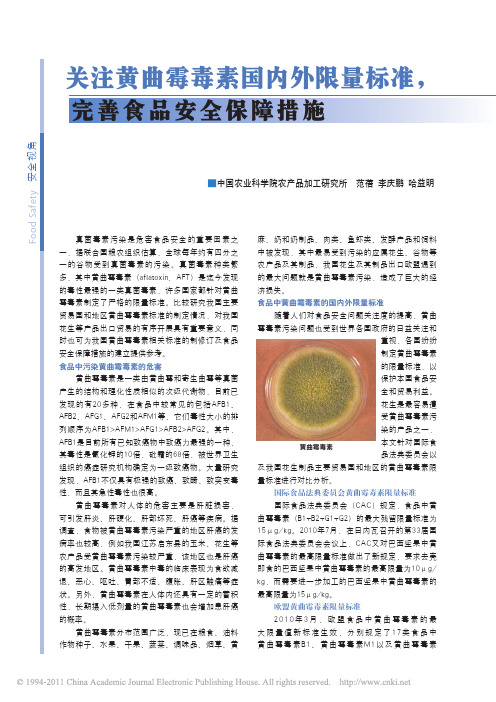
关注黄曲霉毒素国内外限量标准_完善食品安全保障措施
F o o d S a f e t y 安全视角真菌毒素污染是危害食品安全的重要因素之一,据联合国粮农组织估算,全球每年约有四分之一的谷物受到真菌毒素的污染。
真菌毒素种类繁多,其中黄曲霉毒素(aflatoxin, AFT)是迄今发现的毒性最强的一类真菌毒素,许多国家都针对黄曲霉毒素制定了严格的限量标准。
比较研究我国主要贸易国和地区黄曲霉毒素标准的制定情况,对我国花生等产品出口贸易的有序开展具有重要意义,同时也可为我国黄曲霉毒素相关标准的制修订及食品安全保障措施的建立提供参考。
食品中污染黄曲霉毒素的危害黄曲霉毒素是一类由黄曲霉和寄生曲霉等真菌产生的结构和理化性质相似的次级代谢物,目前已发现的有20多种,在食品中较常见的包括AFB1、AFB2、AFG1、AFG2和AFM1等,它们毒性大小的排列顺序为AFB1>AFM1>AFG1>AFB2>AFG2。
其中,AFB1是目前所有已知致癌物中致癌力最强的一种,其毒性是氰化钾的10倍,砒霜的68倍,被世界卫生组织的癌症研究机构确定为一级致癌物。
大量研究发现,AFB1不仅具有极强的致癌、致畸、致突变毒性,而且其急性毒性也很高。
黄曲霉毒素对人体的危害主要是肝脏损害,可引发肝炎、肝硬化、肝部坏死、肝癌等疾病。
据调查,食物被黄曲霉毒素污染严重的地区肝癌的发病率也较高,例如我国江苏启东县的玉米、花生等农产品受黄曲霉毒素污染较严重,该地区也是肝癌的高发地区。
黄曲霉毒素中毒的临床表现为食欲减退、恶心、呕吐、胃部不适、腹胀、肝区触痛等症状。
另外,黄曲霉毒素在人体内还具有一定的蓄积性,长期摄入低剂量的黄曲霉毒素也会增加患肝癌的概率。
黄曲霉毒素分布范围广泛,现已在粮食、油料作物种子、水果、干果、蔬菜、调味品、烟草、黄麻、奶和奶制品、肉类、鱼虾类、发酵产品和饲料中被发现,其中最易受到污染的应属花生、谷物等农产品及其制品,我国花生及其制品出口欧盟遇到的最大问题就是黄曲霉毒素污染,造成了巨大的经济损失。
实验32 数字示波器-讲义

fx ny 3 f y 几种方法?
五、实验内容及要求
1、熟悉信号发生器与数字示波器的相关旋钮和使用方法; 2、连接信号发生器与示波器,观察相关波形;
(1)调节信号发生器相关旋钮,分别设置信号为方波、正弦波和三角波,500Hz,5.00Vpp,偏移-2.500VDC,占空
“AutoSet”,在示波器上显示出稳定的波形,示波器显示的时基按钮选择“X-Y”,示波器以李萨如图模式显示; (4)保持 CH1 输入端信号发生器的频率不变(fx=600Hz),调节 CH2 输入端信号发生器的频率,使屏中出现大小
适中的图形,即出现如讲义中所示的李莎如图形,计算出 fy,读出信号发生器上 CH2 输入端信号的频率 fy,比较 fy 和 fy。 利用李萨如图形测频率 (拍照片)
手动测量 以下练习将详细说明手动波形测量方法。 将示波器复位到已知起点,并使用前面板控件创建如下所示的显示。
1
通常,要获得最高的精度,需要在垂直方向上调节波形,以使其尽量填充显示器。在本 练习中,保持如上所示的波形。 按下默认设置 (Default Setup) 前面板按钮 按下自动设置 (AutoSet) 前面板按钮 使用前面板上的垂直刻度 (Scale) 旋钮,将垂直刻度系数调节为 1 V/格; 使用前面板上的垂直位置 (Position) 旋钮,将波形定位到显示器底部; 使用前面板上的水平刻度 (Scale) 旋钮,将水平刻度系数设置为 250μs/格; 练习 通过计算刻度上的垂直格数,并用格数乘以垂直刻度系数,确定信号的幅度。
值值值值值值值值值值值值
信号
1
6
绝对 误差 信号 2 绝对 误差
4、利用李萨如图形测信号频率 (1)调节信号发生器相关旋钮,设置两个信号为正弦波; (2)按下信号发生器面板上输出按钮“output”,信号经信号线输出; (3)将两信号发生器分别从示波器的 CH1 输入端和 CH2 输入端输入,按下示波器面板上自动设置按钮
考研联考逻辑穆勒关于因果关系的五法

考研联考逻辑穆勒关于因果关系的五法一、契合法:考察几个出现某一被研究现象的不同场合,如果各个不同场合除一个条件相同外,其他条件都不同,那么,这个相同条件就是某被研究现象的原因。
因这种方法是异中求同,所以又叫做求同法。
契合法可用下列公式表示:场合先行情况被研究现象①ABC a②ADE a③AFG a…所以A是a的原因1960年,英国某农场十万只火鸡和小鸭吃了发霉的花生,在几个月内得癌症死了。
后来,用这种花生喂羊、猫、鸽子等动物,又发生了同样的结果。
1963年,有人又用发了霉的花生喂大白鼠、鱼和雪貂,也都纷纷得癌而死,上述各种动物患癌症的前提条件中,对象、时间、环境都不同,唯一共同的因素就是吃了发霉的花生。
于是,人们推断:吃了发霉的花生可能是这些动物得癌死亡的原因。
后来通过化验证明,发霉的花生内含黄曲霉素,黄曲霉素是致癌物质。
这个推断就是通过契合法得出的。
当人们对醋,柠檬汁、碳酸矿水和盐酸进行实验时,会有许多现象发生其中一条,它们都能使石蕊试纸变红。
上面所列物质的化学性质显然极不相同,醋和柠檬汁是有机化合物,碳酸矿水和盐酸是无机化合物。
但它们都有一个共同的性质:酸性。
因此,我们可以按契合法得出结论:酸性这种情况与否蕊纸变红这种现象之间可能有因果关系。
在此例中还有一个共同的特性就是,这四种物质都是液体。
如果单纯按契合法这种逻辑形式,我们也可以得出结论:液体是石蕊变红的原因,这显然是不对的,因此,契合法在实行过程中还必须与相应的理性知识相结合,在能够得出几种推论的时候,用相应的理性知识在其中作出鉴别。
为了提高契合法结论的可靠性,应注意两点:①结论的可靠性和考察的场合数量有关。
考察的场合越多,结论的可靠性越高;②有时在被研究的各个场合中,共同的因素并不只一个,因此,在观察中就应当通过具体分析排除与被研究现象不相关的共同因素。
二、差异法:比较某现象出现的场合和不出现的场合,如果这两个场合除一点不,同外,其他情况都相同,那么这个不同点就是这个现象的原因。
FINALE 2005快速入门(吴粤北编写)
FINALE 2005快速入门吴粤北编写第一课 Finale绘谱基本操作技巧一.建立新的总谱1.标题、作者名、版权:在菜单File(文件)/File Info(文件信息)中直接输入Title(标题)、Composer(作曲家)和Copyright(版权)等信息;或选择文本工具(Text Tool),进入菜单Text/Edit Text对话框,再进子菜单Text/Insert/Title或Composer等编辑,可改字体、字号等;或直接选择文本工具,双击[Title]按钮并将其划黑后,改写歌名或加副标题;同样在Composer中改写作者名。
2.设定调号:选择调号工具(Key Signiature Tool),双击某谱行的指定小节,进入调号设定对话框,首先决定调式,这与临时升降号的正确表达有关;选择调性;还可以决定调号的小节范围(Measure Region)。
这里的Transposition Options主要为设置移调乐器的调号与MIDI发音音高同步为目的。
可以在变调号时决定已有的音符是否随之改变音高-向上或向下移调,或者保持原音高不变(Hold Note to Original Pitches);如果改变移调,则是否按新的调性调式作等音变换(Enharmonically)。
还有一项或许对作曲者有一点用的功能:Hold Notes to Same Staff Lines (Modally)是可以在变调时音符中的自然音的音高保持在新的调式框架内不变,而临时变化音则按新的调式要求改变音高。
3.设定拍号:选择拍号工具(Time Signature Tool),双击某小节指定谱行或用鼠标右键进入拍号设定对话框,通过右侧“拍数”(Number of Beats)和“拍值”(Beat Duration)上的滑杆来选择拍号,注意:八分音符拍值有两种,它们是两种不同的符尾联组方式,此功能设置非常有意义;通过Composite可选择或写入“合成拍号”,如,即在下行第一个空格中写入8,在上行第一个空格中写入3+2+2;也可以是像的复合拍号。
信号发生器afg-2005
信号发生器afg-2005
信号发生器 AFG-2005 是一种功能强大的仪器,用于产生各种
类型的电子信号。
它通常被用于电子设备测试、通信系统调试、传
感器校准等领域。
AFG-2005 可以产生各种波形,包括正弦波、方波、三角波、脉冲波等。
用户可以通过控制面板或者远程控制软件来调
节频率、幅度、相位等参数,以生成所需的信号。
AFG-2005 通常具有较宽的频率范围和较高的精度,可以满足不
同应用的需求。
它还可能具有多种调制功能,如调频调幅、频率调制、脉宽调制等,以模拟各种复杂的信号环境。
此外,一些 AFG-2005 还具有存储和回放信号的功能,方便用户对特定信号进行分析
和比较。
在实际应用中,AFG-2005 的使用非常广泛。
例如,在电子制造
业中,它常被用于测试和校准各种电子设备,如滤波器、放大器、
传感器等。
在通信系统领域,AFG-2005 可以用于调试射频电路、模
拟电路和数字信号处理系统。
同时,它还可以被用于教学和科研领域,帮助学生和研究人员理解和分析各种信号特性。
总的来说,AFG-2005 作为一种高性能的信号发生器,具有广泛
的应用前景,可以为各种领域的专业人士提供强大的信号生成和分析能力。
希望这些信息能够帮助你更好地了解 AFG-2005 信号发生器。
真菌毒素

真菌毒素真菌是微生物中的高等生物,是一类有细胞壁,不含叶绿素,无根叶茎,以腐生或寄生方式生存,能进行有性或无性繁殖的微生物。
自然界中的真菌分布十分广泛,并可作为食品中正常菌相的一部分用来加工食品,但在特定情况下又可造成食品的腐败变质。
有些真菌本身不仅作为病原体引发人类疾病,其代谢产物真菌毒素(mycotoxins)也对人及动物造成危害。
真菌毒素是农产品的主要污染物之一,人畜进食被其污染的粮油食品可导致急、慢性真菌毒素中毒症(myco—toxicc)ses)。
我国是一个农业大国,小麦、玉米、大米及花生等是居民的主要食品原料,每年因霉变而导致25000t粮食不能食用。
出口粮食由于真菌毒素超过输入国限量标准而遭警告或降低等级的现象时有发生。
某些食物中毒、慢性病及癌症的发生与摄入含有真菌毒素的食品有关。
1985~1992年,我国河南、广西、河北、安徽和江苏等省的部分地区共发生由赤霉病麦或霉玉米导致的人畜脱氧雪腐镰刀菌烯醇(deoxvnivalenol,DON)中毒15起。
特别是在1991年春夏之交,我国部分省市遭受特大洪涝灾害,受灾严重的安徽、江苏、河南等省正值小麦收获季节,暴雨使小麦的收割、脱粒等操作无法进行,导致大量小麦发霉,仅安徽一省就有13万多人因食用霉变小麦而发生急性中毒,严重危害了人民的身体健康。
一、真菌毒素的种类目前为止,全世界已经发现了300多种结构不同的真菌毒素,其中已经被分离鉴定的有20多种。
Hesseltine就真菌毒素对农业及人类健康的危害程度和对社会经济发展影响的重要性,对世界上30多个国家和地区进行了调查,结果表明,排在第一位的是黄曲霉毒素,其次为赭曲霉毒素A(ochratoxin A,0TA)、单端孢霉烯族化合物、玉米赤霉烯酮(zearalenone,ZEN)、橘青霉素(citrinin)、杂色曲霉素(sterigmatocystins,ST)、展青霉素(patulin,Pat)、圆弧偶氮酸(cycloplazonlc acid,CPA)等,该项调查进行之时伏马菌素(fumonisins,FMs)尚未被发现。
ISO-14496-4-AMD-3-2005.pdf

Reference numberISO/IEC 14496-4:2004/Amd.3:2005(E)© ISO/IEC 2005INTERNATIONALSTANDARD ISO/IEC 14496-4Second edition2004-12-15AMENDMENT 32005-04-15Information technology — Codingof audio-visual objects —Part 4:Conformance testingAMENDMENT 3: Visual new levels and toolsTechnologies de l'information — Codage des objets audiovisuels —Partie 4: Essai de conformitéAMENDEMENT 3: Nouveaux niveaux et outils visuelsISO/IEC 14496-4:2004/Amd.3:2005(E)PDF disclaimerThis PDF file may contain embedded typefaces. In accordance with Adobe's licensing policy, this file may be printed or viewed but shall not be edited unless the typefaces which are embedded are licensed to and installed on the computer performing the editing. In downloading this file, parties accept therein the responsibility of not infringing Adobe's licensing policy. The ISO Central Secretariat accepts no liability in this area.Adobe is a trademark of Adobe Systems Incorporated.Details of the software products used to create this PDF file can be found in the General Info relative to the file; the PDF-creation parameters were optimized for printing. Every care has been taken to ensure that the file is suitable for use by ISO member bodies. In the unlikely event that a problem relating to it is found, please inform the Central Secretariat at the address given below.© ISO/IEC 2005All rights reserved. Unless otherwise specified, no part of this publication may be reproduced or utilized in any form or by any means, electronic or mechanical, including photocopying and microfilm, without permission in writing from either ISO at the address below or ISO's member body in the country of the requester.ISO copyright officeCase postale 56 • CH-1211 Geneva 20Tel. + 41 22 749 01 11Fax + 41 22 749 09 47***********************Web Published in Switzerlandii © ISO/IEC 2005 – All rights reservedISO/IEC 14496-4:2004/Amd.3:2005(E)ForewordISO (the International Organization for Standardization) and IEC (the International Electrotechnical Commission) form the specialized system for worldwide standardization. National bodies that are members of ISO or IEC participate in the development of International Standards through technical committees established by the respective organization to deal with particular fields of technical activity. ISO and IEC technical committees collaborate in fields of mutual interest. Other international organizations, governmental and non-governmental, in liaison with ISO and IEC, also take part in the work. In the field of information technology, ISO and IEC have established a joint technical committee, ISO/IEC JTC 1.International Standards are drafted in accordance with the rules given in the ISO/IEC Directives, Part 2.The main task of the joint technical committee is to prepare International Standards. Draft International Standards adopted by the joint technical committee are circulated to national bodies for voting. Publication as an International Standard requires approval by at least 75 % of the national bodies casting a vote.Attention is drawn to the possibility that some of the elements of this document may be the subject of patent rights. ISO and IEC shall not be held responsible for identifying any or all such patent rights.Amendment 3 to ISO/IEC 14496-4:2004 was prepared by Joint Technical Committee ISO/IEC JTC 1, Information technology, Subcommittee SC 29, Coding of audio, picture, multimedia and hypermedia information.© ISO/IEC 2005 – All rights reserved iiiISO/IEC 14496-4:2004/Amd.3:2005(E)© ISO/IEC 2005 – All rights reserved 1Information technology — Coding of audio-visual objects — Part 4:Conformance testingAMENDMENT 3: Visual new levels and toolsAdd the following subclause at the end of Clause 5:5.9 Conformance for New Levels of Video Profiles5.9.1 Specification of the test bitstreams5.9.1.1 Test Bitstreams — GeneralAs the bitstreams related to Simple Scalable Profile Level 0 and Advanced Simple Profile Level 3b only invoke tools already defined in ISO/IEC 14496-2:2001, reference is made to bitstream definitions of ISO/IEC 14496-4 Visual bitstream specifications.5.9.1.2 Test Bitstreams5.9.1.2.1 #SCS-12Bitstream : Base layer: pv_scs12.bits, enhancement layer: pv_scs12_e.bitsSpecification : Temporal scalability with P-VOP in the enhancement layer. There is one P-VOP between every two base layer VOPs with ref_select_code == 1.Functional stage : P-VOP temporal prediction from the base layer.Purpose : Verify that the decoder handles P-VOP based temporal scalability.5.9.1.2.2 #SCS-13Bitstream : Base layer: pv_scs13.bits, enhancement layer: pv_scs13_e.bitsSpecification : Spatial scalability with temporally corresponding P-VOP in the enhancement layer, with ref_select_code == 3.Functional stage : P-VOP spatial prediction from the base layer.Purpose : Verify that the decoder handles P-VOP based spatial scalability.5.9.1.2.3 #SCS-14Bitstream : base layer: pv_scs14.bits, enhancement layer: pv_scs14_e.bitsSpecification : Temporal scalability with B-VOP in the enhancement layer. There is one B-VOP between every two base layer VOPs with ref_select_code == 3.ISO/IEC 14496-4:2004/Amd.3:2005(E)Functional stage: B-VOP temporal prediction from the base layer.Purpose: Verify that the decoder handles B-VOP based temporal scalability.5.9.1.2.4 #SCS-15Bitstream:Base layer: pv_scs15.bits, enhancement layer: pv_scs15_e.bitsSpecification: Spatial scalability with temporally corresponding B-VOP in the enhancement layer, withref_select_code == 0.Functional stage: B-VOP spatial prediction from the base layer.Purpose: Verify that the decoder handles B-VOP based spatial scalability.5.9.1.2.5 #A1GE-10Bitstream: mobile_a1ge10.bitsSpecification: A series of consecutive progressively coded P-VOPs. As many quarter-sample components as possible in both the horizontal and vertical directions, luminance and chrominance blocks. Number of MB/s and bitrate are the maximum allowed for the profile-and-level combination. Maximize number of prediction blocks required to reconstruct a macroblock.Functional stage: Prediction bandwidth.Purpose: Check that decoder handles largest prediction bandwidth with progressively coded P-VOPs including quarter-sample interpolation. This test is similar to Test bitstream GEQ#3, except that it uses progressive VOPs.5.9.1.2.6 #A1GE-11Bitstream:stefan_a1ge11.bitsSpecification: A series of consecutive progressively coded S(GMC)-VOPs. As many affine warping transformations (no_of_sprite_warping_points==3) with 1/16 pixel accuracy (sprite_warping_accuracy==3) as possible, luminance and chrominance blocks. Number of MB/s and bitrate are the maximum allowed for the profile-and-level combination. Maximize number of prediction blocks required to reconstruct a macroblock.Functional stage: Prediction bandwidth.Purpose: Check that decoder handles largest prediction bandwidth with progressively coded S(GMC)-VOPs. This test is similar to Test bitstream GEG#3, except that it uses progressive VOPs.5.9.1.2.7 #A1GE-12Bitstream:mobile_a1ge12.bitsSpecification: A bitstream with a series of consecutive progressively coded B-VOPs with bi-directional macroblock motion compensation. Sequence contains many consecutive B-VOPs. Number of MB/s and bitrate are the maximum allowed for the profile-and-level combination. Use quarter-sample prediction in both the horizontal and vertical directions, for all luminance and chrominance blocks. Maximize number of prediction blocks required to reconstruct a macroblock.Functional stage: Prediction bandwidth.Purpose: Check that decoder can cope with this case of worst case bandwidth including quarter-sample interpolation. This test is similar to Test bitstream GEQ#1, except that it uses progressive VOPs.2 © ISO/IEC 2005 – All rights reservedISO/IEC 14496-4:2004/Amd.3:2005(E)© ISO/IEC 2005 – All rights reserved 35.9.1.2.8 #A1GE-13Bitstream : stefan_a1ge13.bitsSpecification : A bitstream with I-, P- and B-VOPs, with quarter-sample motion vectors that are as large as permitted by the profile-and-level combination.Functional stage : Reconstruction of motion vectors, MCP, control.Purpose : Check that decoder implements motion compensation especially for quarter-sample interpolation properly when motion vectors are very large.5.9.2 Normative Test Suites for Simple Scalable Profile Level 0 and Advanced Simple Profile Level 3b NOTE Each row represents a single bitstream. A single bitstream is prepared independently of level for static test, while a single bitstream is prepared for each level @ a profile for dynamic test.Legend:S — Bitstream is intended for functional testD — Bitstream is intended for dynamic testX — Bitstream is for functional and dynamic testProfile NameCategories Bitstream Donated by Bitstream Name Simple ScalableAdvanced Simple L0L3b General SCS-12 PacketVideo pv_scs12.bits XSCS-12_e PacketVideo pv_scs12_e.bits XSCS-13 PacketVideo pv_scs13.bits XSCS-13_e PacketVideo pv_scs13_e.bits XSCS-14 PacketVideo pv_scs14.bits XSCS-14_e PacketVideo pv_scs14_e.bits XSCS-15 PacketVideo pv_scs15.bits XSCS-15_ePacketVideo pv_scs15_e.bits X A1GE-10Philips mobile_a1ge10.bits X A1GE-11Philips stefan_a1ge11.bits X A1GE-12Philips mobile_a1ge10.bits XA1GE-13 Philips stefan_a1ge13.bitsXISO/IEC 14496-4:2004/Amd.3:2005(E)ICS 35.040Price based on 3 pages© ISO/IEC 2005 – All rights reserved。
multisim 波特图示仪
销售合同合同编号:RL-20150124兹经买卖双方同意,由买方购进,卖方售出下列货物,并按下列条款签订本合同:一、本合同于_2015_年_01_月_24_日签订,有效期限:_2015_年_12_月_31_日;二、质量要求和技术标准:卖方企业标准,国家行业标准;卖方承诺因质量问题一周免换,一年保修;三、验收方式及提出异议期限:货到后一周内完成验收,如半个月内没有反馈视为合格;四、交货地址及联系人:_____当地物流_____________________________________五、发票及付款方式:_____银行转账_______________________________________六、包装:____木箱______,应采用适合于运输,防潮、防震、防锈、耐搬运之坚固包装材料,由于包装不良而发生的损失由卖方负担;七、交货时间:1到2周八、发货方式:卖方快递到买方指定地点九、违约责任:十、其他约定事项:本合同履行过程中如出现争议,双方友好协商解决,协商不成时,,由卖方所在地有管辖权的人民法院裁决;十一、本合同一式两份,买卖双方各执一份。
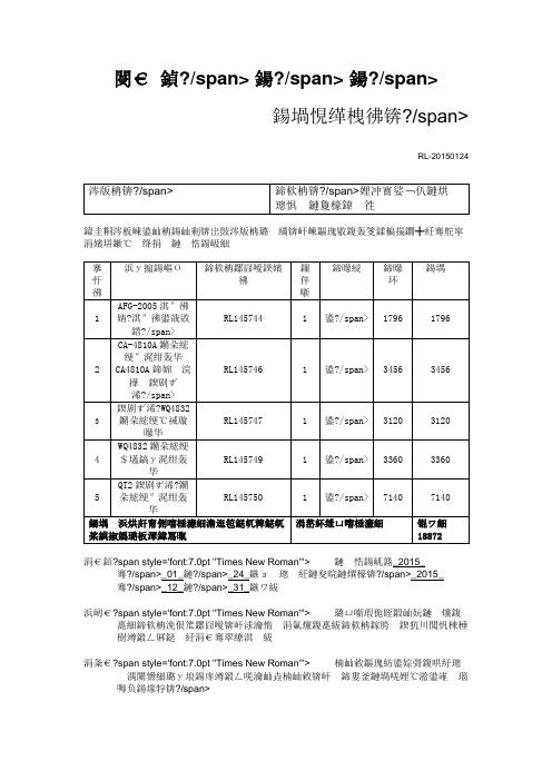
合同经签字盖章后有效(合同传真件有效)AFG-2005信号源信号发生器AFG-2005 任意波形信号发生器* 0.1Hz~5/12/25MHz全数字合成信号,0.1Hz分辨率* 内置标准波形:正弦波、方波、三角波、噪声波和任意波* 20MSa/s采样率、10位垂直分辨率、4k点记录长度的任意波形编辑功能* 1%~99%方波占空比调整* 全数字操作设计与旋钮微调功能* 3.5’’三色 LCD屏幕,同时显示幅值、直流偏压和其它按键设置信息* AM/FM/FSK调变信号,扫描和计频功能(仅AFG-2100系列)* USB Device接口,用于远程控制和波形编辑* 配备PC任意波形编辑软件规格AFG-2105 AFG-2112AFG-2125AFG-2005AFG-2012 AFG-2025波形正弦波/方波/三角波任意波功能采样率20MSa/s 重建率10MHz 记录长度4k点垂直分辨率10位频率特性范围正弦波/方波0.1Hz~5MHz0.1Hz~12MHz0.1Hz~25MHz0.1Hz~5MHz0.1Hz~12MHz0.1Hz~25MHz三角波/锯齿波1MHz分辨率0.1Hz稳定度±20ppm老化率±1ppm/year误差容忍<10mHz输出特性幅值范围≤20MHz:1mVpp~10Vpp (接50Ω);2mVpp~20Vpp (开路)≤25MHz:1mVpp~5Vpp (接50Ω);2mVpp~10Vpp (开路) 精确度设定值的±1%±1mVpp;(1kHz, >10mVpp) 分辨率0.1mV或3位平坦度±1%(0.1dB)≤100kHz;±3%(0.3dB)≤5MHz;±5%(0.4dB)≤12MHz;±20%(2dB)≤20MHz;±5%(0.4dB)≤25MHz;(正弦波1kHz)单位Vpp,Vrms,dBm直流偏移范围±5Vpk ac+dc (接50Ω);±10Vpk ac+dc (开路) 精确度设定值的1%+2mV+幅值的0.5%波形输出阻抗50Ω典型值(固定);>10MΩ(输出关闭)保护短路保护;过载继电器自动禁止输出SYNC输出准位TTL-compatible into>1kΩ阻抗50Ω正常值上升/下降时间≤25ns正弦波特性谐波失真-55dBc DC~1MHz, Ampl>1Vpp;45dBc 1MHz~5MHz, Ampl>1Vpp;-30dBc 5MHz~20MHz,Ampl>1Vpp方上升/下降时间最大输出时,≤25ns(接50Ω负载)波特性过激信号 <5%不对称性 周期的1%+1ns可调占空比 1%~99%≤100kHz;10%~90%≤2MHz;20.0%~80.0%≤5MHz;40.0%~60.0%≤10MHz;50%≤25MHz ;(全频段1%的分辨率) 三角波特性线性度 <峰值输出的0.1% 可调对称性 0%~100%(0.1%的分辨率) AM 调制 载波波形 正弦波、方波、三角波 ——调变波形 正弦波、方波、三角波 调变频率 2mHz~20kHz(Int);DC~20kHz(Ext) 深度 0%~120.0%FM 调制 载波波形 正弦波、方波、三角波 调变波形 正弦波、方波、三角波 调变频率 2mHz~20kHz(Int);DC~20kHz(Ext) 偏差 DC~最大频率FS K 载波波形 正弦波、方波、三角波 调变波形 50%占空比方波 内部频率 2mHz~20kHz 频率范围 0.1Hz~最大频率 扫描 扫描时间 1ms~500s波形种类 正弦波、方波、三角波 扫描形态 线性或对数 开始/截止频率 0.1Hz~最大频率 计频器范围 5Hz~150MHz 精确度 时基精确度±1count 时基 ±20ppm(23℃±5℃),热机30分钟分辨率 最大分辨率:对于1Hz ,100nHz ;对于100MHz ,0.1Hz 输入阻抗 1M Ω/150pf灵敏度≤35mVrms(5Hz~100MHz);≤45mVrms(100MHz~150MHz )存储/调取10组存储设置接口USB(Devices)电源AC 100~240V,50~60Hz 功率消耗65VA尺寸&重量266(W)×107(H)×293(D)mm;约3.2kg266(W)×107(H)×293(D)mm;约3.1kgCA-4810A晶体管图示仪 CA4810A半导体管图示仪长度341毫米宽度510毫米高度251毫米重量13.5Kg∙用户使用手册∙高压测试台(选配)∙电源线∙合格证AC输入220 VAC ±10%电压AC 输入频率50 Hz±2Hz视在功率非测试状态:约50VA最大功率:约110VA 图示仪 WQ4832晶体管测试仪详细信息晶体管图示仪 WQ4832集电极扫描信号输出电压范围及电流容量0~5V 10A0~10V 5A0~50V 1A0~100V 0.5A0~500V 0.1A0~5000V 5mA0~500VAC 0.1A功耗限制电阻:0~500kΩ分11档基极阶梯信号阶梯电流 0.5μA/级~100mA/级,分17档阶梯电压 0.05V级~1V/级,分5档Y轴偏转系数集电极电流 0.5μA/div~1A/div,分20档二极管电流 50nA/div~1μA/div,分5档X轴偏转系数集电极电压 10mV/div~50V/div,分12档一般性能适应电源AC220V±10% 50Hz±4%视在功率约50VA(非测试状态)约80VA(最大功率)外形尺寸320×210×400mm重量 18kgWQ4832晶体管特性图示仪WQ4832型晶体管特性图示仪采用示波管显示半导体器件的各种特性曲线。
黄曲霉毒素对畜禽的危害、检测及去毒方法

黄曲霉毒素对畜禽的危害、检测及去毒方法王晓晓;王宝维;王鑫;逄淑梅;孙超【摘要】黄曲霉毒素(AF)是由某些真菌产毒菌株产生的次生代谢产物,具有极强的毒性.对大多数动物都有强烈的毒性作用,主要是改变饲料的适口性,降低饲料的营养价值,影响动物繁殖机能,导致动物繁殖机能紊乱.本文主要介绍了黄曲霉毒素对畜禽的危害以及薄层色谱(TLC)检测法、高效液相色谱(HPLC)检测法、酶联免疫(ELISA)检测法和放射免疫(RIA)检测法等检测方法,并对黄曲霉毒素的去毒方法做一综述.【期刊名称】《中国饲料》【年(卷),期】2011(000)013【总页数】4页(P33-36)【关键词】黄曲霉毒素;危害;检测;生物降解【作者】王晓晓;王宝维;王鑫;逄淑梅;孙超【作者单位】青岛农业大学优质水禽研究所;青岛农业大学优质水禽研究所;青岛农业大学优质水禽研究所;青岛康大分析检测有限公司;青岛康大食品有限公司【正文语种】中文【中图分类】S816.3黄曲霉毒素(Aflatoxins,AF)是由某些存在于粮食和饲料上的黄曲霉菌(Aspergillus flavus)产生的有毒代谢产物,是最常见的一类真菌毒素,它具有很强的致癌、致畸和致突变的作用,对人和动物都有很强的毒性(李敏等,2008;谭清华,2008)。
黄曲霉多生长在含水量高的作物中,如:玉米、稻谷、棉籽粕、豆类等,在温暖潮湿的环境中大量繁殖并产生毒素(潘耀荣,2008;蔡双双,2007)。
目前,饲料中AF的污染现象普遍存在,已引起人们的广泛关注(史莹华,2007)。
AF是一类结构和理化性质相似的真菌次级代谢物,目前已发现有20种之多,已确定结构的有黄曲霉毒素 B1(AFB1)、黄曲霉毒素 B2(AFB2)、黄曲霉毒素M1(AFM1)等18种,它们的基本结构中都含有二呋喃环和氧杂萘邻酮,前者为其毒性结构,后者可能与其致癌有关(马志科,2009)。
1 对畜禽的危害1.1 对实质器官的损害在AF中,已知毒性大小的排列顺序为AFB1>AFM11>AFG1>AFB2>AFG,AFB1是已知最强的经口致癌物质,以损坏动物肝脏为主要特征。
- 1、下载文档前请自行甄别文档内容的完整性,平台不提供额外的编辑、内容补充、找答案等附加服务。
- 2、"仅部分预览"的文档,不可在线预览部分如存在完整性等问题,可反馈申请退款(可完整预览的文档不适用该条件!)。
- 3、如文档侵犯您的权益,请联系客服反馈,我们会尽快为您处理(人工客服工作时间:9:00-18:30)。
±5Vpk ac+dc (接50Ω);±10Vpk ac+dc (开路)
精确度
设定值的1%+2mV+幅值的0.5%
波形输出阻抗
50Ω典型值(固定);>10MΩ(输出关闭)
保护
短路保护;过载继电器自动禁止输出
SYNC输出准位
TTL-compatible into>1kΩ
阻抗
50Ω正常值
上升/下降时间
10组存储设置
接口
USB(Devices)
电源
AC 100~240V,50~60Hz
功率消耗
65VA
尺寸&重量
266(W)×107(H)×293(D)mm;约3.2kg
266(W)×107(H)×293(D)mm;约3.1kg
0.1Hz~5MHz
0.1Hz~12MHz
0.1Hz~25MHz
三角波/锯齿波
1MHz
分辨率
0.1Hz
稳定度
±20ppm
老化率
±1ppm/year
误差容忍
<10mHz
输出特性
幅值范围
≤20MHz:1mVpp~10Vpp (接50Ω);2mVpp~20Vpp (开路)
≤25MHz:1mVpp~5Vpp (接50Ω);2mVpp~10Vpp (开路)
≤25ns
正弦波特性
谐波失真
-55dBc DC~1MHz, Ampl>1Vpp;45dBc 1MHz~5MHz, Ampl>1Vpp;-30dBc 5MHz~20MHz,Ampl>1Vpp
方波特性
上升/下降时间
最大输出时,≤25ns(接50Ω负载)
过激信号
<5%
不对称性
周期的1%+1ns
可调占空比
1%~99%≤100kHz;10%~90%≤2MHz;20.0%~80.0%≤5MHz;40.0%~60.0%≤10MHz;50%≤25MHz;(全频段1%的分辨率)
调变频率
2mHz~20kHz(Int);DC~20kHz(Ext)
偏差
DC~最大频率
FSK
载波波形
正弦波、方波、三角波
调变波形
50%占空比方波
内部频率
2mHz~20kHz
频率范围
0.1Hz~最大频率
扫描
扫描时间
1ms~500s
波形种类
正弦波、方波、三角波
扫描形态
线性或对数
开始/截止频率
0.1Hz~最大频率
三角波特性
线性度
<峰值输出的0.1%
可调对称性
0%~100%(0.1%的分辨率)
AM调制
载波波形
正弦波、方波、三角波
——
调变波形
正弦波、方波、三角波
调变频率
2mHz~20kHz(Int);DC~20kHz(Ext)
深度
0%~120.0%
FM调制
载波波形
正弦波、方波、三角波
调变波形
正弦波、方波、三角波
精确度
设定值的±1%±1mVpp;(1kHz,>10mVpp)
分辨率
0.1mV或3位
平坦度
±1% (0.1dB)≤100kHz;±3% (0.3dB)≤5MHz;±5% (0.4dB)≤12MHz;
±20% (2dB)≤20MHz;±5% (0.4dB)≤25MHz;(正弦波1kHz)
单位
Vpp,Vrms,dBm
AFG-2005
规格
AFG-2105
AFG-2112
AFG-2125
AFG-2005
AFG-2012
AFG-2025
波形
正弦波/方波/三角波
任意波功能
采样率
20MSa/s
重建率
10MHz
记录长度
4k点
垂直分辨率
10位
频率特性
范围正弦波/方波
0.1Hz~5MHz
0.1Hz~12MHz
0.1Hz~25MHz
计度
时基精确度±1count
时基
±20ppm(23℃±5℃),热机30分钟
分辨率
最大分辨率:对于1Hz,100nHz;对于100MHz,0.1Hz
输入阻抗
1MΩ/150pf
灵敏度
≤35mVrms(5Hz~100MHz);≤45mVrms(100MHz~150MHz)
存储/调取