Phase Diagram of the Two Dimensional Lattice Coulomb Gas
std22安休茨22型电罗经说明书
std22安休茨22型电罗经说明书RaytheonAnschützGmbHPostfach1166D--24100KielGermanyTel+49--431--3019--0Fax+49--431--3019--501EmailService@www.raytheon--anschuetz.deSTD22CompactGYROCOMPASSandSTD22GYROCOMPASSType110--233InstallationandServicemanual3646/110--233.DOC010302Edition:Revision:Revision:Revision:Revision:May20,2005Oct.12,2006Feb.05,2007March27,2007Oct.05,2007 WeitergabeMitteilungzugestanden.ihressowieZuwiderhandlungenInhaltesVervielf?ltigungnichtgestattet,dieserverpflichtensoweitUnterlage,zunichtVerwertungundSchadenersatz.ausdrücklichToutecommunicationoureproductiondecedocument,touteexploitationou communicationdesoncontenusontinterdites,saufautorisationexpresse.To utmanquementàcetterègleestilliciteetexposesonauteurauversementded ommagesetintérêts.Copyingofthisdocument,andgivingittoothersandtheu seorcommunicationofthecontentsthereof,areforbiddenwithoutexpressau thority.Offendersareliabletothepaymentofdamages.Sinnuestraexpresaau torización,quedaterminantementeprohibidalareproduccióntotaloparciald eestedocumento,asícomosuusoindebidoy/osuexhibiciónocomunicacióna terceros.Delosinfractoresseexigiráelcorrespondienteresarcimientodeda? osyperjuicios.InstallationandServicemanualCompassSTD22CompassSTD22CompactCompassSTD22MaintenanceplanDeclarationofConformitySafetynotes..............................................11.122.12.22.32.3.12.3.1.12.42.4.12.4.1.12.4.1.22.4.1.32.4.1.42.52.5.12.5.1.12.5.1.22.5.1.32.5.1.42.5.1.52.62.6.12.6.22.6.32.6.3.12.6.42.6.4.12.6.4.22.6.4.32.6.4.42.6.4.52.6.4.62.6.4.7Generalinformation......................................CANbus(CAN=ControllerArea Network)...................PreparingtoinstalltheSTD22CompactGyroCompass... .STD22CompactCompass–ScopeofSupply................Generalinformationco ncerninginstallationoftheSTD22CompactCompass...........................Creatingcableconnections. ................................Generalinformationconcerningon-boardwiring........... ....Generalinformationaboutcreatinganearthconnection........Installingthe compassandputtingitintooperation.............Removethetransportationsup portwithoutersphere,supportingliquidanddistilledwater...........................Assemblingthecompas senclosure..........................Installationofthegyrosphere............................. ...Fillingwithdistilledwaterandsupportingliquid................Insertingtheoute rsphereinthecompassenclosure...........Creatingcableconnectionsandplugc onnections..............OverviewofplugconnectionsandfusesonPCB‘s............. ConnectingthecoursereceiverintheSTD22CompactGyroCompass.......................ConnectingstatusandcontrolsignaloutputsintheSTD22CompactGyroCompass.......................Connectingsignalinputsf orQSandSECintheSTD22CompactGyrocompass.......................Connectingthepowersup plycable..........................Connectingthecompasstoearth............................ Installationandcommissioningofoptionalfeatures............Installationandco mmissioningoftheAdditionalOutputBox143--103..........................Installationandcommis sioningoftheAC/DCConverter121--062InstallationandcommissioningoftheOperatorUnitQuickSettling(QS)130--606..............InstallingtheOpera torUnitQuickSettling....................Switchingon,settlingandadjustment....... .................Switchingonthecompass..................................Checksonthecom pass....................................SettingtheSTD22CompactCompassintooperati on..........Settingthecompasszero(referencecourse).................Readingthea lignmenterror................................SettingChannel1andChannel2............... .............SettingtheinformationsourceforSpeedErrorCorrection.......I1313151516171720212122252729313133353739404141434647494949 5153565760Edition:Oct.05,20073646/110--233.DOC010302InstallationandServicemanualCompassSTD22CompassSTD22Compact2.6.4.82.6.4.933.13.1.13.23.2.13.2.1.13.33.3.13.3.1.13.3.1.23.3.1.33.3.1.43.43.4.13.4.23.4.2.13.4.2.23.4.2.33.4.2.43.4.2.53.4.33.4.3.13.4.3.23.4.3.33.4.3.43.4.3.53.4.3.63.4.3.7455.15.1.15.1.25.1.35.1.45.1.566.16.1.16.1.1.16.2Adjustmentofessentialoperatingmodes.....................F unctioncheckonexternallyconnectedcoursereceivers.......Preparingtoinsta lltheSTD22GyroCompass.............STD22Compass–ScopeofSupply............... ..........GeneralinformationconcerninginstallationoftheSTD22Compass....... .............................Creatingcableconnections.................................Generalinformationconcerningon-boardwiring...............Generalinformationabout creatinganearthconnection........Installingthecompassandputtingitintoop eration.............Removethetransportationsupportwithoutersphere,suppo rtingliquidanddistilledwater..........................Assemblingthecompassenclo sure..........................Installationofthegyrosphere................................Fillin gwithdistilledwaterandsupportingliquid................Insertingtheouterspher einthecompassenclosure...........Creatingcableconnectionsandplugconnec tions..............OverviewofplugconnectionsandfusesonPCB‘s.............CreatingacableconnectionfromSTD22Compass→DistributionUnit........................Connectingtothepowersupply(Distributio nUnit).............ConnectingtheCANbusplug...............................Settingtheju mpersfortheCANbus.........................Switchingtheterminationresistorsfort heCANbus(E10only)..Connectingthecompasstoearth............................Swi tchingon,settlingandadjustment........................Checksonthecompass....... .............................Switchingonthecompass..................................Settingth ecompasszero(referencecourse)..................Readingthealignmenterror...... ..........................SettingtheCANbusaddress...............................Adjustment sofessentialoperatingmodes....................Functioncheckonexternallyconn ectedcoursereceivers,FunctioncheckofRoT.....................................Fuses,ju mper,LED‘s,buttonsandplugs...................DIPSWITCHsettings...................... ...............OverviewoffunctionsofallDIPswitchsettings................Adjustmen tsofparameters(inascendingorderoffunction).....Adjustmentsofparameters(inascendingorderoftheirappearance)......................7segmentdisplaysan dtheirmeaning........................FunctionaldescriptionofDIPswitchsettings(f orgeneraluse)...FunctionaldescriptionofDIPswitchsettings(SEC)............Tas kstobeperformedregularly...........................Changingthesupportingliquida nddistilledwater..............Removingtheouterspherefromthecompassenclo sure.......Drainingout/fillinginthesupportingliquidanddistilledwater....Clea ningofthegyrosphereandtheoutersphere.. (6771737374757578797)9808385878989919293949596979799101103105106113115117118122 1241261271641841841841861893646/110--233.DOC010302IIEdition:Fe b.05,2007InstallationandServicemanualCompassSTD22CompassSTD22CompactCo mpassSTD2277.17.27.2.17.2.27.2.37.2.47.2.58Errormessagesandwarnings.............................Errormessages.................. .........................Warnings.................................................Warning1“Fanfail ure”.....................................Warning2“Heaterfailure”.................................. Warning3“Supportingliquid>60°C”.........................Warning4“Supporti ngliquidleveltoolow”....................Warning5“Voltagecut-off”....................... ...........NMEA--Formats..........................................ET--Catalogue(Pages1to4)Annex1--8(PCBwithcomponentviewanddesignations)1921921941951961 96197197198Drawings:GyroCompassDimensionalDrawing110D233HP005GyroCompassCablean dConnectionDiagram110--233HP009Sheets1to3GyroCompassCableandConnectionDiagram(E10)110--233.HP029Sheets1to3GyroCompassCableandConnectionDiagram110--233HP010AdditionalOutputBoxDimensionalDrawing146--103.HP005AdditionalOutputBoxWiringDiagram146--103.HP007AC/DCConverterDimensionalDrawing121--062.HP005OperatorUnitQuickSettlingDimensionalDrawing130E606HP005GyroCompassSTD22,WiringDiagram110--233.HP008Sheets1+2TerminalStripPCB,CircuitDiagram110--233.HP016Edition:Feb.05,2007III3646/110--233.DOC010302InstallationandServicemanualCompassSTD22CompassSTD22Compactintentionallyleftblank3646/110--233.DOC010302IVEdition:May20,2005InstallationandServicemanualCompassSTD22CompassSTD22CompactCo mpassSTD22Edition:Oct.05,2007V3646/110--233.DOC010302InstallationandServicemanualCompassSTD22CompassSTD22Compactintentionallyleftblank3646/110--233.DOC010302VIEdition:May20,2005InstallationandServicemanualCompassSTD22CompassSTD22CompactCo mpassSTD22Edition:March27,2007VII3646/110--233.DOC010302InstallationandServicemanualCompassSTD22CompassSTD22Compact3646/110--233.DOC010302VIIIEdition:March27,2007InstallationandServicemanualCompassSTD22CompassSTD22CompactCo mpassSTD22Edition:March27,2007IX3646/110--233.DOC010302InstallationandServicemanualCompassSTD22CompassSTD22CompactIntentionallyleftblank3646/110--233.DOC010302XEdition:May20,2005InstallationandServicemanualCompassSTD22CompassSTD22CompactCo mpassSTD22Edition:March27,2007XI3646/110--233.DOC010302InstallationandServicemanualCompassSTD22CompassSTD22Compact3646/110--233.DOC010302XIIEdition:March27,2007InstallationandServicemanualCompassSTD22CompassSTD22CompactCo mpassSTD22Edition:March27,2007XIII3646/110--233.DOC010302InstallationandServicemanualCompassSTD22CompassSTD22Compact3646/110--233.DOC010302XIVEdition:March27,2007InstallationandServicemanualCompassSTD22CompassSTD22CompactCo mpassSTD22SafetynotesCaution:--Maintenanceandrepairworkshouldbecarriedoutonlybytrainedandqualifiedstaffwhoarewellversedinnationalsafetyregulations.--Afterthegyrocompasshasbeenswitchedoffitisnecessarytowaitatleast15minutesbeforeaccessingtheinteriorofthegyrocompass.Otherwisethespherecouldbedamaged!--Neverswitchoffthecompassatsea,thespherecouldbedamaged.------Itisadvisabletoleavethegyrocompassswitchedonwhenlyinginportforperi odsofuptooneweek.Ifwarningsoccur,theoperationofthegyroequipmentisn otrestricted.Ifthecauseoftheproblemisrectifiedquickly,itispossibletopreve nttheequipmentfrombreakingdown.Pleaseinformtheauthorisedservicest aff(viathehotline).Refertotheservicemanualasappropriate.Whenerrormes sagesappear,theheadingisnolongerdisplayedonthecompass;theheadingisnotfolloweduponaconnectedcoursereceiver.Thecompassmustberepairedbywelltrainedstaff.Pleaseno tethatallship‘sof500grosstonnageandupwardsaccor-dingtoSOLA Sregulationsmustbeequippedwithagyrocompass.Thegyrocompassmustbe operational.Forthisreasonitisnotallo-wedtohaveaswitched--offgyroduring voyages.Aswitched--offgyrocompassduringvoyagescouldcausedamagetothegyros phere.Edition:May20,200513646/110--233.DOC010302InstallationandServicemanualCompassSTD22CompassSTD22CompactCausedbytechnicalprogressthePC--BoardsoftheGyroCompassarechanged.Du etothatsomepicturesand/orprocedureshavebeenchanged.Respectivecha ngesaremarkedwith“E10”.TheACsupplyvoltage(shipsmains)maydropout.Thisleadstoarestartofthegy rocompassandanewsettlingstage.Theheadinginformationduringthissettlin gstagehasareducedaccuracy.Thereforeacontinouslysupplywith24VDCsho uldbeguar-anteed.Itisrecommendedtoactivatespeederrorcorrectioninordertoobtainaccurat eheadinginformation.ThisappliesalsoiftheheadinginformationisusedbyDP systems.PleasepayattentiontotherequirementsoftheDPsystem manufacturer.Supportingliquidshouldbestoredinacold,dryanddarkplace.Pleasepourawa yliquidleftovers.Donotmixsupportingliquids.Thereisareducedaccuracyofthecompassduringthesettlingstage.Thecompa ssshowsrequiredaccuracyafterendingofthesettlingstage(appr.4hoursafter switchingON).3646/110--233.DOC0103022Edition:Sept.12,2006InstallationandServicemanualCompassSTD22CompassSTD22CompactCo mpassSTD221GeneralinformationTheSTD22CompactCompassandtheSTD22Compassareidenticalgyrocomp asses.ThedifferencebetweenthetwogyrocompassesisthattheSTD22GyroCompa sscanbeoperatedviaaCANbussystemwithanOperatorUnitandaDistribution Unit.InthecaseoftheSTD22CompactGyroCompass,theCANbusisnotenable d.Thefollowingdiagramsprovideanoverviewofthepossibleapplicationsofth eSTD22CompactandSTD22GyroCompasses.Edition:May20,200533646/110--233.DOC0103023646/110--233.DOC010302s--NMEASpeed--NMEAPosition--PulseLog--PulseLogDirection--StatusQuickSettlingOperatorUnit(Option)STD22CompactCompassNG001--2xHeading RMGcoursebusorNMEA--1xstatussignal--1xRMGCoursebusforOutputbox Outputbox--1xNMEA0183superfast50Hz--1xstep(6steps/degree) InstallationandServicemanualCompassSTD22CompassSTD22Compact4Edition:Feb.17,2006STD22CompactGyroCompassEdition:Feb.17,2006InstallationandServicemanualCompassSTD22CompassSTD22Compact5ebusDistributionUnitcompactxoutputs,separateadjustable:therCoursebus,NMEA1orNMEA2atussignals :ystemfailureompassfailureompassavaailable--1xROTorheadinganalogue--1xCourseprinter--3xStepSTD22Compass3646/110--233.DOC0103023646/110--233.DOC010302MEASpeed--NMEAPosition--PulseLog--PulseLogDirectionDistributionUnit:--8xHeadingRMGcoursebusorNMEA--3xStep(6steps/deg ree),24/35VDC,max.10W--1xRS232serialinterfaceforprinter--1xrateofturn +/--10Vfor30/100/300degrees/min--12xStatus(potentialfree) .:3647manualno.:3648InstallationandServicemanualCompassSTD22CompassSTD22Compact622GMGyroCompassSystem*=Gyro/Magnet)Edition:Feb.17,20061xRS232forprinterAC/DCconvertersdependsontheneces-sarymax.powero fallsupplieddevices*ThenumberofnecessaryEdition:May20,2005--NMEASpeed--NMEAPosition--PulseLog--PulseLogDirectionDistributionUnit:--8xHeadingRMGcoursebusorNMEA--3xStep(6steps/deg ree),24/35VDC,max.10W--1xRS232serialinterfaceforprinter--1xrateofturn +/--10Vfor30/100/300degrees/min--12xStatus(potentialfree) MaInstallationandServicemanualCompassSTD22CompassSTD22Compact715forprinterGGMGyroCompassSystem*Gyro/Gyro/Magnet)AC/DCconvertersdependsontheneces-sarymax.powerofallsupplieddevice s*ThenumberofnecessarySTD22Compass3646/110--233.DOC0103023646/110--233.DOC010302eedsitionDirection2CompactCompassNG001adingRMGcoursebusorNME AtussignalUnitadingRMGcoursebusorNMEAp(6steps/degree),24/35VDC, max.10W232serialinterfaceforprintereofturn+/--10Vfor30/100/300degrees/mintatus(potentialfree)anualno.:3648InstallationandServicemanualCompassSTD22CompassSTD22Compact8Edition:Feb.17,2006AC/DCconvertersdependsontheneces-sarymax.powerofallsupplieddevice sThenumberofnecessaryompassSystem*agnet)Edition:Feb.17,2006ing(12x)busorNMEA3xStepofturnxRS232forprinterebusorNMEAe),24/35VDC,max.10Wceforprinterfor30/100/300degrees/ minee)InstallationandServicemanualCompassSTD22CompassSTD22Compact9puts(Deviation)hastobetributionUnits3646/110--233.DOC010302STD22CompassbusorNMEA,24/35VDC,max.10Wforprinterr30/100/300degrees/min) 3646/110--233.DOC010302manualno.:3648InstallationandServicemanualCompassSTD22CompassSTD22Compact101xRS232forprinterEdition:Feb.17,2006AC/DCconvertersdependsontheneces-sarymax.powerofallsupplieddevice syroCompassSystem*lite/Magnet)Edition。
crystal_melt_phase_diagrams晶体-熔体相图
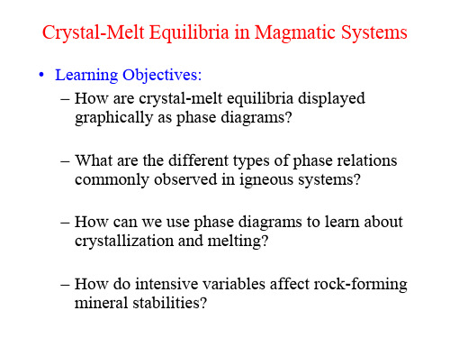
• Learning Objectives: – How are crystal-melt equilibria displayed graphically as phase diagrams? – What are the different types of phase relations commonly observed in igneous systems? – How can we use phase diagrams to learn about crystallization and melting? – How do intensive variables affect rock-forming mineral stabilities?
Enstatite melting yields liquid richer in silica.
Equilibrium vs. Fractional Crystallization
Equilibrium Crystallization: crystals continuously react and re-equilibrate with the melt at P-T-X conditions change. Melt-xtal reactions are reversible Fractional Crystallization: Crystals are immediately isolated, removed, or fractionated from the residual melt so that no further reactions can occur. Melt-xtal reactions are irreversible.
材料科学基础名词解释中英

《材料科学基础》名词解释AOrowan mechanism (奥罗万机制)位错绕过第二相粒子,形成包围第二相粒子的位错环的机制。
Austenite(奥氏体)碳在γ-Fe中形成的间隙固溶体称为奥氏体。
B布拉菲点阵除考虑晶胞外形外,还考虑阵点位置所构成的点阵。
Half-coherent interface(半共格相界)两相邻晶体在相界面处的晶面间距相差较大,则在相界面上不可能做到完全一一对应,于是在界面上将产生一些位错,以降低界面弹性应变能。
这时两相原子部分保持匹配,这样的界面称为半共格界面。
Sheet texture(板织构)轧板时形成的组织的择优取向。
Peritectic reaction(包晶反应)固相和液相生成另一成分的固溶体的反应Peritectic segregation(包晶偏析)新生成的固相的芯部保留残余的原有固相,新相本身成分也不均匀。
Peritectic phase diagram(包晶相图)具有包晶反应的相图Peritectoid reaction(包析反应)由两个固相反应得到一个固相的过程为包析反应。
Cellular structure(胞状结构)成分过冷区很小时,固相突出部分局限在很小区域内,不生成侧向枝晶。
Intrinstic diffusion coefficient(本征扩散系数)依赖热缺陷进行的扩散的扩散系数。
Transformed ledeburite(变态莱氏体)渗碳体和奥氏体组成的莱氏体冷却至727℃时奥氏体发生共析反应转变为珠光体,此时称变态莱氏体。
Deformation twins(变形孪晶)晶体通过孪生方式发生塑性变形时产生的孪晶(BCC,HCP)Chill zone(表层细晶区)和低温铸模模壁接触,强烈过冷形成的细小的方向杂乱的等轴晶粒细晶区。
Burger’s vector(柏氏矢量)表征位错引起的晶格点阵畸变大小和方向的物理量。
Asymmetric tilt boundary(不对称倾斜晶界)晶界两侧晶粒不对称的小角度晶界,界面含两套垂直的刃型位错。
锂离子电池基础科学问题(Ⅷ)——负极材料

万方数据万方数据万方数据万方数据万方数据万方数据万方数据万方数据锂离子电池基础科学问题(Ⅷ)——负极材料作者:罗飞, 褚赓, 黄杰, 孙洋, 李泓, LUO Fei, CHU Geng, HUANG Jie, SUN Yang, LI Hong作者单位:中国科学院物理研究所,北京,100190刊名:储能科学与技术英文刊名:Energy Storage Science and Technology年,卷(期):2014,3(2)1.Armand M;Murphy D;Broadhead J Materials for Advanced Batteries 19802.Garreau M;Thevenin J;Fekir M On the processes responsible for the degradation of the aluminum lithium electrode used as anode material in lithium aprotic electrolyte batteries 1983(3-4)3.Yazami R;Touzain P A reversible graphite-lithium negative electrode for electrochemical generators 1983(3)4.Tarascon J MorSe6:A new solid-state electrode for secondary lithium batteries 1985(9)5.Scrosati B Non aqueous lithium cells 1981(11)6.Abraham K Ambient temperature secondary lithium batteries using LiA1 lithium insertion anodes 19877.Hrold A Recherches sur les composes d'insertion du graphite 1955(7-8)8.Dey A;Sullivan B The electrochemical decomposition of propylene carbonate on graphite 1970(2)9.SONY Non-aqueous electrolyte secondary cell 198910.Nagaura T;Tozawa K Lithium ion rechargeable battery 199011.Endo M;Kim C;Nishimura K Recent development of carbon materials for Li ion batteries 2000(2)12.Mabuchi A A survey on the carbon anode materials for rechargeable lithiumbatteries 199413.Yamaura J;Ozaki Y;Morita A High voltage,rechargeable lithium batteries using newly-developed carbon for negative electrode material 1993(1)14.Tarascon J M;Armand M Issues and challenges facing rechargeable lithium battefies 2001(6861)15.Van S W;gcrosati B Advances in Lithium-Ion Batteries 200216.Kang B;Ceder G Battery materials for ultrafast charging and diseharging 2009(7235)17.Armand M;Tarascon J M Building better batteries 2008(7179)18.Jansen A;Kahaian A;Kepler K Development of a high-power lithium-ion battery 199919.Smith K;Wang C Y Power and thermal characterization of a lithium-ion battery pack for hybrid-electric vehicles 2006(1)20.Zhang X;Ross P;Kostecki R Diagnostic characterization of high power lithium-ion batteries for use in hybrid electric vehicles 2001(5)21.Zhou H H;Ci L C;Liu C Y Progress in studies of the electrode materials for Li ion batteries 1998(1)22.Hao R R;Fang X Y;Niu S C Chemistry of the Elements (Ⅲ) 199823.Ohzuku T;Ueda A;Yamamoto N Zero-strain insertion material of Li(Li1/3Ti5/3)O4 for rechargeable lithium cells 1995(5)24.Woo K C;Mertwoy H;Fischer J Experimental phase diagram of lithium-intercalated graphite 1983(12)25.Dahn J Phase diagram of LixC6 1991(17)26.Nalamova V;Guerard D;Lelaurain M X-ray investigation of highly saturated Li-graphite intercalation compound 1995(2)27.Feng Z Z;Song S Q Preparation and application of mesophase pitch 201328.Honda H;Yamada Y Meso-carbon microbeads 197329.Xu B;Chen E Intermediate development phase carbon microbeads (MCMB),properties and applications 1996(3)30.Niu Y J;Zhang H G;ZhouA M Non-Ferrous Progress:1996-2005 200731.Choi W C;Byun D;Lee J K Electrochemical characteristics of silver-and nickel-coated synthetic graphite preparedby a gas suspension spray coating method for the anode of lithium secondary batteries 2004(2)32.Lee H Y;Baek J K;Lee S M Effect of earbon coating on elevated temperature performance of graphite as lithium-ion battery anode material 2004(1)33.Tanaka H;Osawa T;Moriyoshi Y Improvement of the anode performance of graphite particles through surface modification in RF thermal plasma 2004(1)34.Guoping W;Bolan Z;Min Y A modified graphite anode with high initial efficiency and excellent cycle life expectation 2005(9)35.Lee J H;Lee S;Paik U Aqueous processing of natural graphite particulates for lithium-ion battery anodes andtheir electrochemical performance 2005(1)36.Yamauchi Y;Hino T;Ohzeki K Gas desorption behavior of graphite anodes used for lithium ion secondary batteries 2005(6)37.Zhao X;Hayner C M;Kung M C In-plane vacancy-enabled high-power Si-graphene composite electrode for lithium-ion batteries 2011(6)38.王广驹世界石墨生产,消费及国际贸易 2006(1)39.Jonker G H Magnetic compounds with perovskite structure Ⅳ conducting and non-conducting compounds 195640.Murphy D;Cava R;Zahurak S Ternary LixTiO2 phases from insertion reactions 198341.Ferg E;Gummow R;De K A Spinel anodes for lithium-ion batteries 1994(11)42.Robertson A;Trevino L;Tukamoto H New inorganic spinel oxides for use as negative electrode materials in future lithium-ion batteries 199943.Peramunage D;Abraham K Preparation of micron-sized Li4Ti5O12 and its electrochemistry in polyacrylonitrile electrolyte-based lithium cells 1998(8)44.Julien C;Massot M;Zaghib K Structural studies of Li4/3Me5/3O4 (Me=Ti,Mn) electrode materials:Local structure and electrochemical aspects 2004(1)45.Scharner S;Weppner W;Schmid B E Evidence of two-phase formation upon lithium insertion into the Li1.33Ti1.67O4 spinel 1999(3)46.Zaghib K;Simoneau M;Armand M Electrochemical study of Li4Ti5O12 as negative electrode for Li-ion polymer rechargeable batteries 199947.Pecharroman C;Amarilla J Thermal evolution of infrared vibrational properties of Li4/3Ti5/3O4 measured by specular reflectance 2000(18)48.Guerfi A;Charest P;Kinoshita K Nano electronically conductive titanium-spinel as lithium ion storage negative electrode 2004(1)49.Gao L;Qiu W;Zhao H L Lithiated titanium complex oxide as negative electrode 2005(1)50.Bach S;Pereira R J;Baffier N Electrochemical properties of sol-gel Li4/3Ti5/3O4 199951.Kavan L;Grtzel M Facile synthesis of nanocrystalline Li4Ti5O12 (spinel) exhibiting fast Li insertion 2002(2)52.Hao Y;Lai Q Y;Liu D Synthesis by citric acid sol-gel method and electrochemical properties of Li4Ti5O12 anode material for lithium-ion battery 2005(2-3)53.王虹微波法制备钛酸锂的方法 200854.白莹一种用于锂二次电池负极材料尖晶石钛酸锂的制各方法 200655.Li J;Tang Z;Zhang Z Controllable formation and electrochemical properties of one-dimensional nanostructured spinel Li4Ti5O12 2005(9)56.杨立一种应用于锂离子电池的钛酸锂负极材料的制备方法中国 200857.Huang S;Wen Z;Zhu X Effects of dopant on the electrochemical performance of Li4Ti5O12 as electrode material for lithium ion batteries 2007(1)58.Tian B;Xiang H;Zhang L Niobium doped lithium titanate as a high rate anode material for Li-ion batteries2010(19)59.Huang Y;Qi Y;Jia D Synthesis and electrochemical properties of spinel Li4Ti5Ol2-xClx anode materials forlithium-ion batteries 2012(5)60.Venkateswarlu M;Chen C;Do J Electrochemical properties of nano-sized Li4Ti5O12 powders synthesized by a sol-gel process and characterized by X-ray absorption spectroscopy 2005(1)61.Cai R;Yu X;Liu X Li4Ti5O12/Sn composite anodes for lithium-ion batteries:Synthesis and electrochemical performance 2010(24)62.Yuan T;Yu X;Cai R Synthesis of pristine and carbon-coated Li4Ti5O12 and their low-temperature electrochemical performance 2010(15)63.Hu X;Lin Z;Yang K Effects of carbon source and carbon content on electrochemical performances of Li4Ti5O12/C prepared by one-step solid-state reaction 2011(14)64.Martha S K;Haik O;Borgel V Li4Ti5O12/LiMnPO4 lithium-ion battery systems for load leveling application 2011(7)65.Huang K L;Wang Z X;Liu S Q Lithium-Ion Battery Technology and Key Principles 200866.Xu K;Wang X Y;Xiao L X Lithium Ion Battery 200267.Wang Q;Li H;Chen L Novel spherical microporous carbon as anode material for Li-ion batteries 200268.Li H;Wang Q;Shi L Nanosized SnSb alloy pinning on hard non-graphitic carbon spherules as anode materials for aLi ion battery 2002(1)69.Hu J;Li H;Huang X Influence of micropore structure on Li-storage capacity in hard carbon spherules 2005(11)70.Fey G T K;Chen C L High-capacity carbons for lithium-ion batteries prepared from rice husk 200171.Yin G P;Zhou D R;Xia B J Preparation of phosphorus-doped carbon and its performance Lithium intercalation2000(4)72.Schnfelder H H;Kitoh K;Nemoto H Nanostructure criteria for lithium intercalation in non-doped and phosphorus-doped hard carbons 1997(2)73.Buiel E;Dahn J Li-insertion in hard carbon anode materials for Li-ionbatteries 1999(1)74.Rosamaria F;Ulrich V S;Dahn J R Studies of lithium intercalation into carbons using nonaqueous electrochemical-cells 1990(7)75.Stevens D;Dahn J The mechanisms of lithium and sodium insertion in carbon materials 2001(8)76.Bonino F;Brutti S;Piana M Structural and electrochemical studies of a hexaphenylbenzene pyrolysed soft carbon as anode material in lithium batteries 2006(17)77.Guo M;Wang J C;Wu L B Study of carbon nanofibers as negative materials for Li-ion batteries 2004(5)78.Sato Y;Kikuchi Y;Kawai T Characteristics of coke carbon modified with mesophase-pitch as a negative electrodefor lithium ion batteries 199979.Yoshio M;Tsumura T;Dimov N Electrochemical behaviors of silicon based anode material 2005(1)i S C Solid lithium-silicon electrode 197681.Sharma R A;Seefurth R N Thermodynamic properties of the lithium-silicon system 1976(12)82.Seefurth R N;Sharma R A Investigation of lithium utilization from a lithium-silicon electrode 1977(8)83.Seefurth R N;Sharma R A Dependence of lithium-silicon electrode potential and lithium utilization on reference electrode location 1980(5)84.Wen C J;Huggins R A Chemical diffusion in intermediate phases in the lithium-silicon system 1981(3)85.Boukamp B A;Lesh G C;Huggins R A All-solid lithium electrodes with mixed-conductor matrix 1981(4)86.Weydanz W J;Wohlfahrt M M;Huggins R A A room temperature study of the binary lithium-silicon and the ternary lithium-chromium-silicon system for use in rechargeable lithium batteries 199987.Gao B;Sinha S;Fleming L Alloy formation in nanostructured silicon 2001(11)88.Li H;Huang X J;Chen L Q A high capacity nano-Si composite anode material for lithium rechargeable batteries 1999(11)89.Li H;Huang X J;Chen L Q The crystal structural evolution of nano-Si anode caused by lithium insertion and extraction at room temperature 2000(1-4)90.Limthongkul P;Jang Y I;Dudney N J Electrochemically-driven solid-state amorphization in lithium-silicon alloys and implications for lithium storage 2003(4)91.Hatchard T D;Dahn J R In situ XRD and electrochemical study of the reaction of lithium with amorphous silicon 2004(6)92.Key B;Bhattacharyya R;Grey C P Real-time NMR investigations of structural changes in silicon electrodes for lithium-ion batteries 2009(26)93.Key B;Morcrette M;Grey C P Pair distribution function analysis and solid State NMR studies of silicon electrodes for lithium ion batteries:Understanding the (De) lithiation mechanisms 2011(3)94.Beaulieu L Y;Hatchard T D;Bonakdarpour A Reaction of Li with alloy thin films studied by in situ AFM 2003(11)95.Baggetto L;Danilov D;Notten P H L Honeycomb-structured silicon:Remarkable morphological changes induced by electrochemical (De)lithiation 2011(13)96.Lee S W;Mcdowell M T;Choi J W Anomalous shape changes of silicon nanopillars by electrochemical lithiation2011(7)97.Lee S W;Mcdowell M T;Berla L A Fracture of crystalline silicon nanopillars during electrochemical lithium insertion 2012(11)98.He Y;Yu X Q;Wang Y H Alumina-coated patterned amorphous silicon as the anode for a lithium-ion battery with high coulombic effficiency 2011(42)99.He Y;Wang Y H;Yu X Q Si-Cu thin film electrode with kirkendall voids structure for lithium-ion batteries2012(12)100.He Y;Yu X Q;Li G Shape evolution of patterned amorphous and polycrystalline silicon microarray thin film electrodes caused by lithium insertion and extraction 2012101.Wang Y;He Y;Xiao R Investigation of crack patterns and cyclic performance of Ti-Si nanocomposite thin film anodes for lithium ion batteries 2012102.Notten P H L;Roozeboom F;Niessen R A H3-D integrated all-solid-state rechargeable batteries 2007(24)103.Baggetto L;Oudenhoven J F M;Van D T On the electrochemistry of an anode stack for all-solid-state 3D-integrated batteries 2009(1)104.Chan C K;Ruffo R;Hong S S Surface chemistry and morphology of the solid electrolyte interphase on silicon nanowire lithium-ion battery anodes 2009(2)105.Zheng J Y;Zheng H;Wang R An investigation on the sold electrolyte interphase of silicon anode for Li-ion batteries through force curve method 2013(6)106.Zhang X W;Patil P K;Wang C S Electrochemical performance of lithium ion battery,nano-silicon-based,disordered carbon composite anodes with different microstructures 2004(2)107.Chan C K;Ruffo R;Hong S S Structural and electrochemical study of the reaction of lithium with silicon nanowires 2009(1)108.Cui L F;Ruffo R;Chan C K Crystalline-amorphous core-shell silicon nanowires for high capacity and high current battery electrodes 2009(1)109.Mcdowell M T;Lee S W;Ryu I Novel size and surface oxide effects in silicon nanowires as lithium battery anodes 2011(9)110.Ryu I;Choi J W;Cui Y Size-dependent fracture of Si nanowire battery anodes 2011(9)111.Xu W L;Vegunta S S S;Flake J C Surface-modified silicon nanowire anodes for lithium-ion batteries 2011(20) 112.Yue L;Wang S Q;Zhao X Y Nano-silicon composites using poly (3,4-ethylenedioxythiophene):Poly (styrenesulfonate) as elastic polymer matrix and carbon source for lithium-ion battery anode 2012(3)113.Zang J L;Zhao Y P Silicon nanowire reinforced by single-walled carbon nanotube and its applications to anti-pulverization electrode in lithium ion battery 2012(1)114.Yoshio M;Wang H Y;Fukuda K Carbon-coated Si as a lithium-ion battery anode material 2002(12)115.Qu J;Li H Q;henry J J Self-aligned Cu-Si core-shell nanowire array as a high-performance anode for Li-ion batteries 2012116.Jia H P;Gao P F;Yang J Novel three-dimensional mesoporous silicon for high power lithium-ion battery anode material 2011(6)117.Yao Y;Mcdowell M T;Ryu I Interconnected silicon hollow nanospheres for lithium-ion battery anodes with long cycle life 2011(7)118.Fu K;Yildiz O;Bhanushali H Aligned carbon nanotube-silicon sheets:A novel nano-architecture for flexiblelithium ion battery electrodes 2013(36)119.Min J H;Bae Y S;Kim J Y Self-organized artificial SEI for improving the cycling ability of silicon-basedbattery anode materials 2013(4)120.Choi N S;Yew K H;Lww K Y Effect of fluoroethylene carbonate additive on interfacial properties of silicon thin-film electrode 2006(2)121.Chakrapani V;Rusli F;Filler M A Quaternary ammonium ionic liquid electrolyte for a silicon nanowire-based lithium ion battery 2011(44)122.Etacheri V;Haik O;Goffer Y Effect of fluoroethylene carbonate (FEC) on the performance and surface chemistry of Si-nanowire Li-ion battery anodes 2011(1)123.Buddie M C High performance silicon nanoparticle anode in fluoroethylene carbonate-based electrolyte for Li-ion batteries 2012(58)124.Profatilova I A;Stock C;Schmitz A Enhanced thermal stability of a lithiated nano-silicon electrode by fluoroethylene carbonate and vinylene carbonate 2013125.Leung K;Rempe S B;Foster M E Modeling electrochemical decomposition of fluoroethylene carbonate on silicon anode surfaces in lithium ion batteries 2014(3)126.Kovalenko I;Zdyrko B;Magasinski A A major constituent of brown algae for use in high-capacity Li-ion batteries 2011(6052)127.Ryou M H;Kim J;Lee I Mussel-inspired adhesive binders for high-performance silicon nanoparticle anodes in lithium-ion batteries 2012(11)128.Li J;Lewis R;Dahn J Sodium carboxymethyl cellulose a potential binder for Si negative electrodes for Li-ion batteries 2007(2)129.Bridel J S;Azais T;Morcrette M Key parameters governing the reversibility of Si/carbon/CMC electrodes for Li-ion batteries 2009(3)130.Mazouzi D;Lestriez B;Roue L Silicon composite electrode with high capacity and long cycle life 2009(11)131.Guo J C;Wang C S A polymer scaffold binder structure for high capacity silicon anode of lithium-ion battery 2010(9)132.Liu W R;Yang M H;Wu H C Enhanced cycle life of Si anode for Li-ion batteries by using modified elastomeric binder 2005(2)133.Park H K;Kong B S;Oh E S Effect of high adhesive polyvinyl alcohol binder on the anodes of lithium ionbatteries 2011(10)134.Magasinski A;Zdyrko B;Kovalenko I Toward efficient binders for Li-ion battery Si-based anodes:Polyacrylic acid 2010(11)135.Yun J B;Soo K J;Tae L K Aphoto-cross-linkable polymeric binder for silicon anodes in lithium ion batteries 2013(31)136.Han Z J;Yabuuchi N;Hashimoto S Cross-linked poly (acrylic acid) with polycarbodiimide as advanced binder for Si/graphite composite negative electrodes in Li-ion batteries 2013(2)137.Koo B;Kim H;Cho Y A highly cross-linked polymeric binder for high-performance silicon negative electrodes in lithium ion batteries 2012(35)138.Bae J;Cha S H;Park J A new polymeric binder for silicon-carbon nanotube composites in lithium ion battery 2013(7)139.Yim C H;Abu L Y;Courtel F M High capacity silicon/graphite composite as anode for lithium-ion batteries using low content amorphous silicon and compatible binders 2013(28)140.Erk C;Brezesinski T;Sommer H Toward silicon anodes for next-generation lithium ion batteries:A comparative performance study of various polymer binders and silicon nanopowders 2013(15)141.Kim J S;Choi W;Cho K Y Effect of polyimide binder on electrochemical characteristics of surface-modified silicon anode for lithium ion batteries 2013142.Li J;Christensen L;Obrovac M Effect of heat treatment on Si electrodes using polyvinylidene fluoride binder 2008(3)143.Kim Y L;Sun Y K;Lee S M Enhanced electrochemical performance of silicon-based anode material by using current collector with modified surface morphology 2008(13)144.Guo J C;Sun A;Wang C S A porous silicon-carbon anode with high overall capacity on carbon fiber current collector 2010(7)145.Choi J Y;Lee D J;Lee Y M Silicon nanofibrils on a flexible current collector for bendable lithium-ion battery anodes 2013(17)146.Hang T;Nara H;Yokoshima T Silicon composite thick film electrodeposited on a nickel micro-nanocones hierarchical structured current collector for lithium batteries 2013147.Luais E;Sakai J;Desploban S Thin and flexible silicon anode based on integrated macroporous silicon film onto electrodeposited copper current collector 2013148.Tang X X;Liu W;Ye B Y Preparation of current collector with blind holes and enhanced cycle performance of silicon-based anode 2013(6)149.Kim H;Han B;Choo J Three-dimensional porous silicon particles for use in high-performance lithium secondary batteries 2008(52)150.Bang B M;Kim H;Song H K Scalable approach to multi-dimensional bulk Si anodes via metal-assisted chemical etching 2011(12)151.Kasavajjula U;Wang C;Appleby A J Nano-and bulk-silicon-based insertion anodes for lithium-ion secondary cells 2007(2)152.Magasinski A;Dixon P;Hertzberg B High-performance lithium-ion anodes using a hierarchical bottom-up approach 2010(4)153.Liu G;Xun S;Vukmirovic N Polymers with tailored electronic structure for high capacity lithium battery electrodes 2011(40)154.Chan C K;Peng H;Liu G High-performance lithium battery anodes using silicon nanowires 2007(1)155.Idota Y;Kubota T;Matsufiti A Tin-based amorphous oxide:A high-capacity lithium-ion-storage material 1997(5317)156.Courtney I A;Dahn J Key factors controlling the reversibility of the reaction of lithium with SnO2 and Sn2BPO6 glass 1997(9)157.Li H;Huang X J;Chen L Q Direct imaging of the passivating film and microstructure of nanometer-scale SnO anodes in lithium rechargeable batteries 1998(6)158.Liu W;Huang X J;Wang Z Studies of stannic oxide as an anode material for lithium-ion batteries 1998(1)159.Li H;Wang Z;Chen L Research on advanced materials for Li-ion batteries 2009(45)160.David M New materials extend Li-ion performance 2006(5)161.Ogisu K R&D activities & results for sony batteries 2005162.索尼公司索尼成功开发3.5 A·h高容量锂离子电池"Nexelion" 2011163.Dahn J;Mar R;Abouzeid A Combinatorial study of Sn1-xCox (0《x《 0.6) and (Sn0 55Co0 45)1-yCy (0《 y《 0 5)alloy negative electrode materials for Li-ion battaries 2006(2)164.Todd A;Mar R;Dahn J Tin-transition metal-carbon systems for lithium-ion battery negative electrodes 2007(6) 165.Ferguson P;Martine M;Dunlap R Structural and electrochemical studies of (SnxCo1-x)60C40 alloys prepared by mechanical attriting 2009(19)166.Ferguson P;Rajora M;Dunlap R(Sn0.5Co0 5)1-yCy alloy negative electrode materials prepared by mechanical attriting 2009(3)167.Ferguson P;ToddA;Dahn J Comparison of mechanically alloyed and sputtered tin-cobalt-carbon as an anode material for lithium-ion batteries 2008(1)168.Hassoun J;Mulas G;Panero S Ternary Sn-Co-C Li-ion battery electrode material prepared by high energy ball milling 2007(8)vela P;Nacimiento F;Ortiz G F Sn-Co-C composites obtained from resorcinol-formaldehyde gel as anodes in lithium-ion batteries 2010(1)170.Liu B;Abouimrane A;Ren Y New anode material based on SiO-SnxCoyCz for lithium batteries 2012(24)171.Zhong X C;Jiang F Q;Xin P A Preparation and electrochemical performance of Sn-Co-C composite as anode material for Li-ion batteries 2009(1)172.Yang S;Li Q;Shen D Influence of Fe on electrochemical performance of SnxCoy/C anode materials 2011(2)173.Shaobin Y;Ding S;Qiang L Synthesis and electrochemical properties of Sno.35-0 5xCoo 35-0 5xZnxCo 3o composite 2010(1)174.YangSB;ShenD;WuXG Effects of Cu on structures and electrochemical properties of Sn-Co/C composite 2012(4)175.Cui W;Wang F;Wang J Nanostructural CoSnC anode prepared by CoSnO3 with improved cyclability for high-performance Li-ion batteries 2011(13)176.Li M Y;Liu C L;Shi M R Nanostructure Sn-Co-C composite lithium ion battery electrode with unique stability and high electrochemical performance 2011(8)177.Xin L;Jing Y X;Hai L Z Synthesis and properties of Sn30Co30C40 ternary alloy anode material for lithium ion battery 2013(7)178.Lee S I;Yoon S;Park C M Reaction mechanism and electrochemical characterization of a Sn-Co-C composite anodefor Li-ion batteries 2008(2)179.Fauteux D;Koksbang R Rechargeable lithium battery anodes:Alternatives to metallic lithium 1993(1)180.Rahner D;Machill S;Schlorb H Intercalation materials for lithium rechargeable batteries 1996181.Besenhard J;Hess M;Komenda P Dimensionally stable Li-alloy electrodes for secondary batteries 1990182.Maxfield M;Jow T;Gould S Composite electrodes containing conducting polymers and Li alloys 1988(2)183.Winter M;Besenhard J O Electrochemical lithiation of tin and tin-based intermetallics and composites 1999(1) 184.Du C W;Chen Y B;Wu M S Advances in lithium-ion battery anode materials for non-carbon 2000185.Wu Y P;Wan C R Study on materials for lithium-ion batteries tin-based negative 1999(3)186.Kepler K D;Vaughey J T;Thackeray M M LixCu6Sn5(0《x《13):An intermetallic insertion electrode for rechargeable lithium batteries 1999(7)187.Mao O;Dunlap R;Dahn J Mechanically alloyed Sn-Fe(-C) powders as anode materials for Li-ion batteries:Ⅰ.TheSn2Fe-C system 1999(2)rcher D;Beaulieu L;Macneil D In situ X-ray study of the electrochemical reaction of Li with η'-Cu6Sn52000(5)189.Li H;Zhu G;Huang X Synthesis and electrochemical performance of dendrite-like nanosized SnSb alloyprepared by co-precipitation in alcohol solution at low temperature 2000(3)190.Kim H;Kim Y J;Kim D Mechanochemical synthesis and electrochemical characteristics of Mg2Sn as an anode material for Li-ion batteries 2001(1)191.Wang L;Kitamura S;Sonoda T Electroplated Sn-Zn alloy electrode for Li secondary batteries 2003(10)192.Yin J;Wada M;Yoshida S New Ag-Sn alloy anode materials for lithium-ion batteries 2003(8)193.Tamura N;Fujimoto M;Kamino M Mechanical stability of Sn-Co alloy anodes for lithium secondary batteries2004(12)194.Wang L;Kitamura S;Obata K Multilayered Sn-Zn-Cu alloy thin-film as negative electrodes for advanced lithium-ion batteries 2005(2)195.Beauleiu L;Hewitt K;Turner R The electrochemical reaction of Li with amorphous Si-Sn alloys 2003(2)196.Besenhard J;Yang J;Winter M Will advanced lithium-alloy anodes have a chance in lithium-ion batteries 1997(1) 197.Yang J;Winter M;Besenhard J Small particle size multiphase Li-alloy anodes for lithium-ionbatteries 1996(1) 198.Mukaibo H;Sumi T;Yokoshima T Electrodeposited Sn-Ni alloy film as a high capacity anode material for lithium-ion secondary batteries 2003(10)199.Photo F Nonaqueous secondary battery 1995200.Photo F Nonaqueous secondary battery 1995201.Goodenough J;Manthiram A;James A Lithium insertion compounds 1988202.Aydinol M;Kohan A;Ceder G Abinitio calculation of the intercalation voltage of lithium-transition-metal oxide electrodes for rechargeable batteries 1997(2)203.三星SDI株式会社用于非水电解液电池的负极活性材料,其制备方法和非水电解液电池 2005204.Song J H;Park H J;Kim K J Electrochemical characteristics of lithium vanadate,Li1+xVO2,new anode materials for lithium ion batteries 2010(18)205.Chang J J Synthesis and electrochemical:Properties of lithium-ion battery anode material Li1+xVO2 2012206.Armstrong A R;Lyness C;Panchmatia P M The lithium intercalation process in the low-voltage lithium battery anode Li1+xV1-xO2 2011(3)207.Chen H;Xiang K X;Hu Z L Synthesis and electrochemical performance of new anode materials Li1.1V0 9O2 forlithium ion batteries 2012(5)208.Choi N S;Kim J S;Yin R Z Electrochemical properties of lithium vanadium oxide as an anode material for lithium-ion battery 2009(2)zzari M;Scrosati B A cyclable lithium organic electrolyte cell based on two intercalation electrodes 1980(3) 210.Dipietro B;Patriarco M;Scrosati B On the use of rocking chair configurations for cyelabte lithium organic electrolyte batteries 1982(2)211.Ktakata H O;Meri T;Koshita N Procedures of the symposium onprimary and secondary lithium batteries 1988212.Poizot P;Laurelle S;Grugeon S Nano-sized ttansition-metal oxides as negative-electrode materials for lithium-ion batteries 2000(6803)213.Debart A;Dupont L;Poizot P A transmission electron microscopy study of the reactivity mechanism of tailor-made CuO particles toward lithium 2001(11)214.Dedryvere R;Laruelle S;Grugeon S Contribution of X-ray photoelectron spectroscopy to the study of the electrochemical reactivity of CoO toward lithium 2004(6)215.Xin C;Naiqing Z;Kening S3d transition-metal oxides as anode micro/nano-materials for lithium ion batteries 2011(10)216.Li H;Richter G;Maier J Reversible formation and decomposition of LiF clusters using transition metal fluorides as precursors and their application in rechargeable Li batteries 2003(9)217.Badway F;Mansour A;Pereira N Structure and electrochemistry of copper fluoride nanocomposites utilizing mixed conducting matrices 2007(17)218.Dbart A;Dupont L;Patrice R Reactivity of transition metal (Co,Ni,Cu) sulphides versus lithium:The intriguing case of the copper sulphide 2006(6)219.Gillot F;Boyanov S;Dupont L Electrochemical reactivity and design of NiP2 negative electrodes for secondary Li-ion batteries 2005(25)220.Pereira N;Dupont L;Tarascon J Electrochemistry of Cu3N with lithium a complex system with parallel processes 2003(9)221.Zhang W M;Wu X L;Hu J S Carbon coated Fe3O4 nanospindles as a superior anode material for lithium-ion batteries 2008(24)222.Rahman M;Chou S L;Zhong C Spray pyrolyzed NiO-C nanocomposite as an anode material for the lithium-ion battery with enhanced capacity retention 2010(40)223.Wang Y;Zhang H J;Lu L Designed functional systems from peapod-like Co@carbon to Co3O4@carbon nanocomposites 2010(8)224.Zhou G;Wang D W;Li F Graphene-wrapped Fe3O4 anode material with improved reversible capacity and cyclicstability for lithium ion batteries 2010(18)225.Wang Y;Zhang L Simple synthesis of CoO-NiO-C anode materials for lithium-ion batteries and investigation on its electrochemical performance 2012226.Zhang P;Guo Z;Kang S Three-dimensional Li2O-NiO-CoO composite thin-film anode with network structure forlithium-ion batteries 2009(1)227.Zhu X J;Guo Z P;Zhang P Highly porous reticular tin-cobalt oxide composite thin film anodes for lithium ion batteries 2009(44)228.Wang C;Wang D;Wang Q Fabrication and lithium storage performance of three-dimensional porous NiO as anode for lithium-ion battery 2010(21)229.Xia Y;Zhang W;Xiao Z Biotemplated fabrication of hierarchically porous NiO/C composite from lotus pollen grains for lithium-ion batteries 2012(18)230.Yu Y;Chen C H;Shi Y A tin-based amorphous oxide composite with a porous,spherical,multideck-cage morphology as a highly reversible anode material for lithium-ion batteries 2007(7)231.Li F;Zou Q Q;Xia Y Y Co-loaded graphitable carbon hollow spheres as anode materials for lithium-ion battery 2008(2)232.Wu Z S;Ren W;Wen L Graphene anchored with Co3O4 nanoparticles as anode of lithium ion batteries with enhanced reversible capacity and cyclic performance 2010(6)引用本文格式:罗飞.褚赓.黄杰.孙洋.李泓.LUO Fei.CHU Geng.HUANG Jie.SUN Yang.LI Hong锂离子电池基础科学问题(Ⅷ)——负。
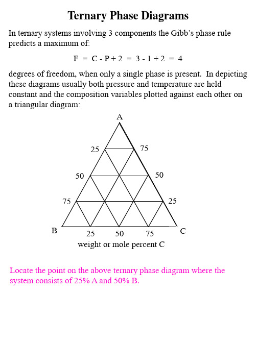
Ternary_Phase_Diagrams
When the system is at an overall composition described by point j in the evaporative sequence: What mass of water remains in the syer has evaporated?
What is the mass of the liquid solution of composition b that remains?
How many grams of KCl and NaCl remain dissolved in this liquid?
How many grams of solid KCl and solid NaCl have precipitated from the solution
The mass of KCl that has precipitated by the time the system has reached point e can be calculated by applying the lever law to a tie line (line gf) that passes through point e and intersects the pure solid KCl corner: mKCl (s) = mtotal (ef / gf) = (mH2O remaining + mKCl + mNaCl ) (ef / gf) = (32 g + 20 g + 10 g) (10 / 152) = 4 grams What is the composition of the liquid solution that is in equilibrium with this 4 grams of precipitated pure solid KCl? When the system has reached point h in the evaporative sequence, it is saturated in NaCl as well as KCl and pure solid NaCl will begin to precipitate from solution. How many degrees of freedom are present at point h? What are the 3 phases that are in equilibrium at point h and what are their compositions? By the time the system composition has reached point j, substantial pure solid NaCl has precipitated from the solution, as well as more pure solid KCl. The solution composition remains fixed at b. When the system has overall composition j, the masses of liquid of composition b and solid mixture that has precipitated can be calculated from a the tie line constructed through segment bj that intesects the pure solid KCl pure solid NaCl axis at point k. Once the mass of the solid mixture at point k is known, another application of the lever law along the tie line that extends along the pure solid KCl pure solid NaCl axis and passes through point k can be used to calculate the masses of pure solid KCl and NaCl that have precipitated from the solution and comprise the solid mixture at point k.
4_bond
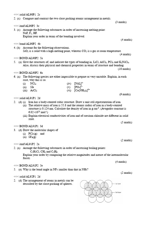
<<< solid/AL90P1_2c2. (c) Compare and contrast the two close packing atomic arrangement in metals.(3 marks)<<< itmf/AL90P2_3c3. (c) Arrange the following substances in order of increasing melting point:NaF, F2, HF.Explain your order in terms of the bonding involved.(4 marks) <<< bond/AL90P2_4b4. (b) Account for the following observations.SiO2 is a solid with a high melting point, whereas CO2 is a gas at room temperature.(4 marks) <<< BOND/AL90P2_5a5. (a) Give the structures of, and indicate the types of bonding in, LiCl, AlCl3, PCl3 and K2NiCl4.Also, discuss their physical and chemical properties in terms of structure and bonding.(10 marks) <<< BOND/AL90P2_6a6. (a) The following species are either impossible to prepare or very unstable. Explain, in eachcase, why this is so.(i) NCl4 (iv) [NaI4]3-(ii) SI6 (v) [PO4]2-(iii) ArCl2 (vi) [Co(NH3)8]3+(9 marks) <<< solid/AL91P1_2d2. (d) (i)Iron has a body-centred cubic structure. Draw a unit cell representation of iron.(ii)The relative mass of iron is 55.8 and the atomic radius of iron in a body-centred structure is 0.124 nm. Calculate the density of iron in g.cm-3. (Avogadro constant is6.02 1023 mol-1)(iii)Explain electrical conductivities of iron and of caesium chloride are different in solid state.(5 marks) <<< BOND/AL91P1_3d3. (d) Draw the molecular shapes of(i)PCl5(g) and(ii)SF6(g)(2 marks) <<< itmf/AL91P2_2a2. (a) Arrange the following substances in order of increasing boiling points:C2H5Cl, CH4 and C2H6.Explain your order by comparing the relative magnitudes and nature of the intermolecularforces(4 marks)<<< BOND/AL91P2_5e5. (e) Why is the bond angle in NF3 smaller than that in NH3?(2 marks) <<< solid/AL92P1_2d2. (d) The arrangement of atoms in metals can bedescribed by the close-packing of spheres.(i)Which close-packed structure does abcabcabc... describe? Indicate on the diagrambelow one tetrahedral hole (marking it T) and one octahedral hole (marking it O).(ii)Describe the bonding in metallic crystals.(iii)Of the three energy ranges in kJ mol -1 given below:5 - 100200 - 700800 - 1500which is the most likely energy range for the change M(s) --> M(g), where M is ametal?(4 marks) <<< BOND/AL92P1_3g3. (g) Draw diagrams showing the shapes of the following molecules. Indicate the lone pairs (if any)on each central atom.(i) ICl (ii) XeOF4(3 marks) <<< BOND/AL92P2_2b2. (b) Give a brief account of the electron density of the hydrogen molecule. Your answer shouldinclude an electron density map.(4 marks) <<< itmf/AL92P2_3a3. (a) (i)Describe the bonding and intermolecular forces in ice and in SiO2 solid.(ii)What type of interactions must be overcome to melt these solids?(4 marks) <<< BOND/AL92P2_3b3. (b) (i)Define the covalent radius of an atom.(ii)State and explain the trends in the covalent radius on going down any group and going across a short period of the periodic table.(iii)The covalent radius of carbon is 0.077 nm. The measured carbon-carbon bond length in benzene is 0.139 nm. Estimate the carbon-carbon bond length in ethane. Explain anydifference in the carbon-carbon bond lengths in these two molecules.(6 marks) <<< BOND/AL93P1_1b1. (b) For each of the following molecules, draw a three-dimensional structure and state themolecular geometry.(i)SiF4(ii)OF2(4 marks) <<< \PM\SOLID AL94 IA 1b1. (b) The crystal structure of a compound A, B, can be described as a simple cubic lattice of A atomswith B atoms at the middle of all the edges.(i)What is the empirical formula of this compound?(ii)What are the coordination numbers of an A atom and a B atom respectively.(2 marks) <<< BOND/AL94P1_1c1. (c) For each of the following molecules, draw a three-dimensional structure showing the positionsof the bond electron pairs and lone electron pairs (if any). In each case, state the moleculargeometry and whether the molecule possesses a non-zero dipole moment.(i)BF3(ii)ClF3(4 marks) <<< itmf/AL94P1_2d2. (d) (i)Explain the term "hydrogen bonding".(ii)Draw a diagram of the structure of a compound which has hydrogen bonds. Indicate the hydrogen bond(s) clearly.(iii)Explain why(I)the boiling point of CH4 is lower than that of SiH4, and(II)the boiling point of NH3 is higher than that of PH3.(5 marks)<<< itmf/AL94P2_2B2. (b) Account for each of the following:(i)Concentrated H3PO4 has a high viscosity.(ii)The melting point of ice decreases with an increase in pressure.(5 marks) <<< BOND/AL95P1_1c1. (c) Account for the fact that the carbon oxygen bond lengths in CO, CO2 and CO32- are 0.113, 0.116and 0.129 nm respectively.(3 marks) <<< BOND/AL95P1_2a2. (a) Explain why phosphorus can form PCl3 and PCl5, while nitrogen can form only NCl3.(2 marks) <<< BOND/AL95P1_2e2. (e) For each of the following species, draw a three-dimensional structure showing the bond electronpairs and lone electron pairs of the central atom. State the shape of the species in each case.(i)ICl4-(ii)SCl2(3 marks) <<< bond/AL96P1_2b2.(b) For each of the following chemical species, draw a three-dimensional structure showing thebond electron pairs and lone electron pair(s) of the central atom underlined. State the shape of the species in each case.(i)ClO3-(ii)NOF(3 marks) <<solid/AL97P1_1a>>Answer ALL questions in this section. Write your answers in the spaces provided.1. (a) At room temperature, iron has a body-centred cubic structure.(i)Draw the unit cell represenation of iron.(ii)Deduce the number of atoms in one unit cell of iron.(2 marks) <<itmf/AL97P1_1d>>1. (d) Explain why(i)the boiling point of HF is higher than that of HCl;(ii)the boiling point of HI is higher than that of HBr.(2 marks) <<bond/AL97P1_3b>>3. (b) For each of the following sulphur-containing chemical species, state its shape and the oxidationstate of sulphur.(i)H2S(ii)SO2(iii)SO42-(3 marks) <<< itmf/AL97P2_1a1. (a) (i)Explain the terms 'dipole' and 'dipole moment', using HBr as an example.(ii)Explain why the dipole moment of HF is greater than that of HI.(iii)State the effect of an electric field on molecules of the following compounds and explain the effect in terms of dipole moment.(7 marks) <<itmf/AL98P1_2b>>2. (b) Which compound, H2O or F2O, would you expect to have a higher boiling point? Explain youranswer.(2 marks) <<BOND/AL98P1_1b>>1. (b) (i) An iodine molecule can be represented by the diagram in theright, with each dot ' ' representing an atomic nucleus.(I) Uisng one or more diagram of this kind, illustrate your understanding of the twoterms 'covalent radius' and van der Waals' radius'.(II) Account for the difference between the covalent radius and van der Waals' radius for iodine.(ii) Explain why the carbon-oxygen bond lengths in CO and CO2 are different.<<bond/AL98P1_3a>>3. (a) For each of the nitrogen-containing chemical species below, state its shape and the oxidation stateof nitrogen(i) NO2-(ii) NH3(iii) NO3-(3 marks) <<< BOND/AL98P2_1c>>1.(c) (i)Draw the three-dimensional structure of BF3.(ii)BF3 reacts with NH3 to form an adduct, BF3.NH3. Account for the formation of the adduct and draw its three-dimensional structure.(4 marks) <<< BOND/AL98P2_2a>>2. (a) The structure of two allotropes of carbon, diamond and graphite, are shown below.(i)Comment on the three different carbon-carbon distances as indicated in the abovestructures.(ii)With reference to the above structures, explain why diamond is hard whereas graphite is soft enough to be used as lubricant.(6 marks) <<< BOND/AL98P2_5a>>5. (a) Consider the following compound F.(i)Give the hybridization states of the carbon atoms, a, b, c and d.(ii)Draw all possible three-dimensional structures for F, indicating the expected bond angles around the carbon atoms, a, b, c and d in one of the structures.<<< bond/AL99P1_1b1-31.(b) Account for each of the following:(i) At 298 K and 1 atm pressure, carbon dioxide is a gas whereas silicon dioxide is a solid..(iii) At 273 K, ice has a smaller density than water.(5 marks) <<< solid/AL99P2_2c>>2 (c) (i) Consider the unit cell of calcium fluoride shown below:(I)State the respective coordination numbers of each calcium ion and each fluorideion.(II)Describe the lattice of calcium ions and that of fluoride ions.(ii) (I)Draw the unit cell of caesium chloride.(II)Describe the lattice of caesium ions and that of chloride ions in caesium chloride.(6 marks) <<< BOND/AL00P1_1a>>1. (a) The diagrams below show the arrangements of atoms, ions or molecules in four crystallinesubstances: graphite, ice, iodine and sodium chloride.(i)Write the name of the substance for each structure in the space provided.(ii)Label, on the diagrams, the type of interactions that are present in these substances.(6 marks) <<< BOND/AL00P1_1b>>1. (b) Explain why nitrogen forms only one chloride, NCl3, whereas phosphorus forms two chlorides,PCl3 and PCl5.(2 marks) <<< itmf/AL00P1_1c>>1. (c) A ccount for the order of boiling point for the two series of compound below:(I)H2O > C2H5OH > C2H5OC2H5(II)H2S > C2H5SH > C2H5SC2H5(3 marks) <<< BOND/AL00P2_2d>>2. (d) Draw three-dimensional structures for methane and carbon dioxide. Give the hybridization stateof the carbon atom in each molecule.(3 marks) <<< BOND/AL00P2_4b>>4. (b) (i)Both argon and xenon (Xe) are Group 0 elements in the Periodic Table. Explain whycompounds of xenon and fluorine exist, whereas compounds of argon and fluorine areunknown.(ii)Draw the three-dimensional structure of xenon(IV) fluoride, showing the bond electron pairs and lone electron pairs of the central atom.(3 marks) <<< BOND/AL01P1_2c>>2. (c) Draw the three-dimensional structure for each molecule below, showing the lone electronpiar(s), if any, of the central atom. State the shape of each molecule.(i) BF3(ii) ClF3(3 marks) <<< BOND/AL01P1_2d>>2. (d) The lattice structure of BaO(s) is described as the interpenetration of two simple cubiclattices, one of Ba2+ ions and the other of O2- ions.(i) Draw the unit cell of BaO(s), labelling the Ba2+ and O2- ions.(ii) What is the coordinaiton number of each O2- ion in the structure?(2 marks) <<< Itmf/AL02P1_3c>>3. (c) (i) Account for the fact that CO2 is a gas while SiO2 is a high melting solid under roomtemperature and atmospheric pressure.(ii) Give the hybridization state of carbon in CO2 and of silicon in SiO2.(4 marks)<<< BOND/AL02P2_1d>>1. (d) Ammonia (NH3) and phosphine (PH3) are hydrides of nitrogen and phosphorusrespectively. Account for each of the following phenomena:(i) The bond angle between two N-H bonds in NH3 (about 107o) is greater than thatbetween two P-H bonds in PH3 (about 94o).(ii) NH3 is very soluble in water but PH3 is sparingly soluble.(4 marks)<<< itmf/AL02P2_2c>>2. (c) The graph below shows the variations of melting points and boiling points of the Period 3elements.Explain why(i) Silicon, metalloid, has a very high melting point;(ii) the boiling points of the metals are in the order:Al > Mg > Na(iii) there is generally a larger difference between the melting point and the boiling point for metals than for non-metals;(iv) the melting point of sulphur is the highest among the non-metals.(9 marks)<<< solid/AL02P2_4b>>4. (b) Both MgO(s) and NaF(s) have a face-centred cubic structure. The table below lists themelting points and solubilities in water of the two compounds.(i) Draw the unit cell of MgO(s)(ii) Account for the following phenomena:(I) The melting point of MgO(s) is higher than that of NaF(s)(II) The solubility of NaF(s) is higher than that of MgO(s)(6 marks)。
基于平衡力矩法的二维弹道修正引信摩擦力矩测试方法

Vol.4"No.1Feb.2021第43卷第1期2021年2月探测与控制学报JournalofDetecton & Control基于平衡力矩法的二维弹道修正引信摩擦力矩测试方法何江杨,高铭泽,霍鹏飞,柳海斌(西安机电信息技术研究所,陕西西安710065)扌商要:针对目前文献未披露二维弹道修正引信摩擦力矩测试方法,仅是在选取的特定条件下对轴承摩擦力矩进行测试,不能满足轴承在二维弹道修正引信中作用时高过载、高转速的工况要求,无法得到轴承在二维弹道修正引信全寿命周期摩擦力矩值的问题,提出了基于平衡力矩法的二维弹道修正引信摩擦力矩测试方法&该方法考虑了轴承装配、高转速和高过载对摩擦力矩的影响,将轴承装配在二维弹道修正引信中,使用马歇特 锤和高速转台分别模拟引信高过载和高转速的环境,通过所设计的装置实现摩擦力矩测试。
试验验证表明,该 方法可有效测得不同转速、经受轴向和径向高过载后二维弹道修正引信摩擦力矩值,测试操作性强,测量条件 范围广。
由数据分析可知转速和径向过载对二维弹道修正引信摩擦力矩值影响较大,轴向过载对摩擦力矩值影响并不明显。
与理论计算值相比,结果更加符合实际,接近真实值&关键词:二维弹道修正引信;摩擦力矩测试;平衡力矩法;高过载;高转速中图分类号:TJ431.3文献标识码:A 文章编号:1008-1194(2021)01-0008-05Two-dimentional Trajectory Correction Fuze Friction MomentTesting Method Based on Balance MomentHE Jiangyang ,GAO Mingze ,HUO Pengfei ,LIU Haibin(Xi'an Institute of Electromechanical Information Technology ,Xi'an 710065,China)Abstract : In view of the fact that the test method of friction moment of the two-dimentional trajectory correc tion fuze is not disclosed in the current literature ,it only tests the friction moment of bearing under the selected specific conditions ,which can not meet the requirements of high overload and high speed when the bearing acts in the two-dimentional trajectory correction fuze and can not get the friction value of bearing in the whole life cy cle of the two-dimensional trajectory correction fuze. For that ,a test method of friction moment of the two-di mensional trajectory correction fuze based on the balance moment method was proposed. In this method ,the influence of bearing assembly ,high speed and high overload on friction moment is considered. The bearings wereassembled in the two-dimensional trajectory correction fuze. The environment of high overload and high speedwas simulated by the Machete hammer and high speed turntable respectively. The friction moment test was real ized by the designed deviceSThe test result showed that the method could e f ectively measure the friction mo ment of the two-dimensional correction fuze in the condition of different speed and high axial and radial overload.The test has strong operability and a wide range of measurement conditions. It could be got from the dada analy-sisOhaOroOaionspeedandradialovercomehadagreaOinfluenceonfricionmomenOvalueofOheOwo-dimensional correction fuze ,while the axial overload had no obvious influence on friction moment value. Compared with the theoretical value ,the result was more practical and close to the real value.Keywords I wo-dimensionalOrajecOorycorrecionfuze ; fricion momenOOesO ; Ohebalance momenOmeOhod ;highoverload ; highspeed"收稿日期:20200926作者简介:何江杨(1991—),男,陕西米脂人,硕士,研究方向:弹道修正引信。
磁共振中一些常用的简化及缩写用语

熔焊原理-4.5 Solidification Path
4.5 Solidification PathConsider the eutectic phase diagram of a binary system A-B shown by the broken lines in Figure 4.21a. To the left of the eutectic point, the primary solidification phase is γ, namely, γ is the first thing to solidify.To the right, the primary solidification phase is α. The solid line represents the solidification path of alloy C0. The arrow in the solidification path indicates the direction in which the liquid composition changes as temperature decreases. At step 1, where the fraction of the liquid phase L is f L= 1, γ begins to form from the liquid phase, assuming negligible undercooling before solidification. The composition of the liquid phase follows the solid line representing L→γ. At step 2, solidification is complete and f L= 0.In the case of a ternary system A-B-C, the phase diagram is three dimensional, with the base plane showing the composition and the vertical direction showing the temperature. The liquidus is a surface (curved) instead of a line as in a binary phase diagram (Figure 4.21a). The intersection between two liquidus surfaces is a line called the line of twofold saturation, instead of a point intersection between two liquidus lines in a binary phase diagram. As shown in Figure 4.21b, when projected vertically downward to the base plane, the liquidus surfaces show areas of primary solidification phases with the lines of twofold saturation separating them.The solid line shows the solidification path of alloy C0. At step 1, where the fraction of the liquid phase L is f L= 1, the solid phase g begins to form from the liquid phase. As temperature decreases, the composition of the liquid phase follows the solid line representing L→γ until the line of twofold saturation m3 is reached. At step 2, the a phase begins to form from the liquid, too. As temperature decreases further, the composition of the liquid phase follows the solid line representing the ternary eutectic reaction L→γ+αuntil the line of twofold saturation 3n is reached. At step 3, the formation of a from the liquid stops and is taken over by the formation of b. As temperature decreases still further, the composition of the liquid phase follows the solid line representing the ternary eutectic reaction L→γ+β. This can go on until the line representing binary A-B (the abscissa) is reached, if there is still liquid available to get there. The fraction of liquid f L = 0 when solidification is complete.Figure 4.21 Solidification paths: (a) a binary A-B system; (b) a ternary A-B-C system.。
CrystGrowthDes晶体生长英文文献

An Infinite Two-Dimensional Hybrid Water-Chloride Network,Self-Assembled in a Hydrophobic Terpyridine Iron(II)MatrixRicardo R.Fernandes,†Alexander M.Kirillov,†M.Fátima C.Guedes da Silva,†,‡Zhen Ma,†JoséA.L.da Silva,†João J.R.Fraústo da Silva,†andArmando J.L.Pombeiro*,†Centro de Química Estrutural,Complexo I,Instituto Superior Técnico,TU-Lisbon,A V.Ro V isco Pais,1049-001Lisbon,Portugal,and Uni V ersidade Luso´fona de Humanidades e Tecnologias,A V.doCampo Grande,376,1749-024,Lisbon,PortugalRecei V ed October18,2007;Re V ised Manuscript Recei V ed January7,2008ABSTRACT:An unprecedented two-dimensional water-chloride anionic{[(H2O)20(Cl)4]4–}n network has been structurally identified in a hydrophobic matrix of the iron(II)compound[FeL2]Cl2·10H2O(L)4′-phenyl-2,2′:6′,2″-terpyridine).Its intricate relief geometry has been described as a set of10nonequivalent alternating cycles of different sizes ranging from tetra-to octanuclear{[(H2O)x(Cl)y]y–}z(x) 2–6,y)0–2,z)4–6,8)fragments.In contrast to the blooming research on structural characterizationof a wide variety of water clusters in different crystalline materials,1much less attention has been focused on the identification anddescription of hybrid hydrogen-bonded water assemblies with othersolvents,small molecules,or counterions.1c,2In particular,thecombination of chloride ions and water is one of the most commonlyfound in natural environments(e.g.,seawater or sea-salt aerosols),and thus the investigation of water-chloride interactions has beenthe object of numerous theoretical studies.3However,only recentlya few water-chloride associates incorporated in various crystalmatrixes have been identified and structurally characterized,4,5including examples of(i)discrete cyclic[(H2O)4(Cl)]–,4a[(H2O)4(Cl)2]2–,4b and[(H2O)6(Cl)2]2–4c clusters,and(ii)variousone-or two-dimensional(1D or2D)hydrogen-bonded networksgenerated from crystallization water and chloride counterionswith{[(H2O)4(Cl2)]2–}n,5b{[(H2O)6(Cl)2]2–}n,5b[(H2O)7(HCl)2]n,5c{[(H2O)11(Cl)7]7–}n,5d{[(H2O)14(Cl)2]2–}n,5e{[(H2O)14(Cl)4]4–}n,5aand{[(H2O)14(Cl)5]5–}n5f compositions.These studies are alsobelieved to provide a contribution toward the understanding of thehydration phenomena of chloride ions in nature and have importancein biochemistry,catalysis,supramolecular chemistry,and designof crystalline materials.5In pursuit of our interest in the self-assembly synthesis andcrystallization of various transition metal compounds in aqueousmedia,we have recently described the[(H2O)10]n,6a(H2O)6,6b and[(H2O)4(Cl)2]2–4b clusters hosted by Cu/Na or Ni metal-organicmatrixes.Continuing this research,we report herein the isolationand structural characterization of a unique2D water-chlorideanionic layer{[(H2O)20(Cl)4]4–}n within the crystal structure of thebis-terpyridine iron(II)compound[FeL2]Cl2·10H2O(1′)(L)4′-phenyl-2,2′:6′,2″-terpyridine).Although this compound has beenobtained unexpectedly,a search in the Cambridge StructuralDatabase(CSD)7,8points out that various terpyridine containinghosts tend to stabilize water-chloride associates,thus also sup-porting the recognized ability of terpyridine ligands in supra-molecular chemistry and crystal engineering.9,10Hence,the simple combination of FeCl2·2H2O and L in tetrahydrofuran(THF)solution at room temperature provides the formation of a deep purple solid formulated as[FeL2]Cl2·FeCl2·5H2O(1)on the basis of elemental analysis,FAB+-MS and IR spectroscopy.11This compound reveals a high affinity for water and,upon recrystallization from a MeOH/H2O(v/v)9/1)mixture,leads to single crystals of1′with a higher water content,which have been characterized by single-crystal X-ray analysis.12The asymmetric unit of1′is composed of a cationic[FeL2]2+ part,two chloride anions,and10independent crystallization water molecules(with all their H atoms located in the difference Fourier map),the latter occupying a considerable portion of the crystal cell. The iron atom possesses a significantly distorted octahedral coordination environmentfilled by two tridentate terpyridine moieties arranged in a nearly perpendicular fashion(Figure S1, Supporting Information).Most of the bonding parameters within [FeL2]2+are comparable to those reported for other iron compounds*To whom correspondence should be sent.Fax:+351-21-8464455.E-mail: pombeiro@ist.utl.pt.†Instituto Superior Técnico.‡Universidade Luso´fona de Humanidades eTecnologias.Figure 1.Perspective representations(arbitrary views)of hybrid water-chloride hydrogen-bonded assemblies in the crystal cell of1′; H2O molecules and chloride ions are shown as colored sticks and balls, respectively.(a)Minimal repeating{[(H2O)20(Cl)4]4–}n fragment with atom numbering scheme.(b)Nonplanar infinite polycyclic2D anionic layer generated by linkage of four{[(H2O)20(Cl)4]4–}n fragments(a) represented by different colors;the numbers are those of Table1and define the10nonequivalent alternating cycles of different size.2008310.1021/cg7010315CCC:$40.75 2008American Chemical SocietyPublished on Web02/08/2008bearing two terpyridine ligands.13The most interesting feature of the crystal structure of 1′consists in the extensive hydrogen bonding interactions of all the lattice–water molecules and chloride coun-terions (Table S1,Supporting Information),leading to the formation of a hybrid water -chloride polymeric assembly possessing minimal repeating {[(H 2O)20(Cl)4]4–}n fragments (Figure 1a).These are further interlinked by hydrogen bonds generating a nonplanar 2D water -chloride anionic layer (Figure 1b).Hence,the multicyclic {[(H 2O)20(Cl)4]4–}n fragment is con-structed by means of 12nonequivalent O–H ···O interactions with O ···O distances ranging from 2.727to 2.914Åand eight O–H ···Cl hydrogen bonds with O ···Cl separations varying in the 3.178–3.234Årange (Table S1,Supporting Information).Both average O ···O [∼2.82Å]and O ···Cl [∼3.20Å]separations are comparable to those found in liquid water (i.e.,2.85Å)14and various types of H 2O clusters 1,6or hybrid H 2O -Cl associates.4,5Eight of ten water molecules participate in the formation of three hydrogen bonds each (donating two and accepting one hydrogen),while the O3and O7H 2O molecules along with both Cl1and Cl2ions are involved in four hydrogen-bonding contacts.The resulting 2D network can be considered as a set of alternating cyclic fragments (Figure 1b)which are classified in Table 1and additionally shown by different colors in Figure 2.Altogether there are 10different cycles,that is,five tetranuclear,three pentanuclear,one hexanuclear,and one octa-nuclear fragment (Figures 1b and 2,Table 1).Three of them (cycles 1,2,and 6)are composed of only water molecules,whereas the other seven rings are water -chloride hybrids with one or two Cl atoms.The most lengthy O ···O,O ···Cl,or Cl ···Cl nonbonding separations within rings vary from 4.28to 7.91Å(Table 1,cycles 1and 10,respectively).Most of the cycles are nonplanar (except those derived from the three symmetry generated tetrameric fragments,cycles 1,2,and 4),thus contributing to the formation of an intricate relief geometry of the water -chloride layer,possessing average O ···O ···O,O ···Cl ···O,and O ···O ···Cl angles of ca.104.9,105.9,and 114.6°,respectively (Table S2,Supporting Information).The unprecedented character of thewater -chloride assembly in 1′has been confirmed by a thorough search in the CSD,7,15since the manual analysis of 156potentially significant entries with the minimal [(H 2O)3(Cl)]–core obtained within the searching algorithm 15did not match a similar topology.Nevertheless,we were able to find several other interesting examples 16of infinite 2D and three-dimensional (3D)water -chloride networks,most of them exhibiting strong interactions with metal -organic matrixes.The crystal packing diagram of 1′along the a axis (Figure 3)shows that 2D water -chloride anionic layers occupy the free space between hydrophobic arrays of metal -organic units,with an interlayer separation of 12.2125(13)Åthat is equivalent to the b unit cell dimension.12In contrast to most of the previously identified water clusters,1,6water -chloride networks,5,16and extended assemblies,1c the incorporation of {[(H 2O)20(Cl)4]4–}n sheets in 1′is not supported by strong intermolecular interactions with the terpyridine iron matrix.Nevertheless,four weak C–H ···O hydrogen bonds [avg d (D ···A))3.39Å]between some terpyridine CH atoms and lattice–water molecules (Table S1,Figure S2,Supporting Information)lead to the formation of a 3D supramolecular framework.The thermal gravimetric analysis (combined TG-DSC)of 117(Figure S3,Supporting Information)shows the stepwise elimination of lattice–water in the broad 50–305°C temperature interval,in accord with the detection on the differential scanning calorimetryTable 1.Description of Cyclic Fragments within the {[(H 2O)20(Cl)4]4–}n Network in 1′entry/cycle numbernumber of O/Cl atomsformula atom numberingschemegeometry most lengthy separation,Åcolor code a 14(H 2O)4O3–O4–O3–O4planar O3···O3,4.28light brown 24(H 2O)4O6–O7–O6–O7planar O7···O7,4.42light gray 34[(H 2O)3(Cl)]-O2–O4–O3–Cl2nonplanar O4···Cl2,4.66blue 44[(H 2O)3(Cl)]-O6–O7–O9–Cl1nonplanar O7···Cl1,4.61green 54[(H 2O)2(Cl)2]2-O9–Cl1–O9–Cl1planar Cl ···Cl1,4.76pink 65(H 2O)5O2–O4–O3–O10–O8nonplanar O2···O10,4.55red75[(H 2O)4(Cl)]-O1–O5–O7–O9–Cl1nonplanar O7···Cl1,5.25pale yellow 85[(H 2O)4(Cl)]-O1–O5–Cl2–O8–O10nonplanar O10···Cl2,5.29orange 96[(H 2O)4(Cl)2]2-O2–O8–Cl2–O2–O8–Cl2nonplanar Cl2···Cl2,7.12yellow 108[(H 2O)6(Cl)2]2-O1–O10–O3–Cl2–O5–O7–O6–Cl1nonplanarCl1···Cl2,7.91pale blueaColor codes are those of Figure 2.Figure 2.Fragment of nonplanar infinite polycyclic 2D anionic layer in the crystal cell of 1′.The 10nonequivalent alternating water or water -chloride cycles are shown by different colors (see Table 1for color codes).Figure 3.Fragment of the crystal packing diagram of 1′along the a axis showing the intercalation of two water -chloride layers (represented by space filling model)into the metal -organic matrix (depicted as sticks);color codes within H 2O -Cl layers:O red,Cl green,H grey.Communications Crystal Growth &Design,Vol.8,No.3,2008783curve(DSC)of three major endothermic processes in ca.50–170, 170–200,and200–305°C ranges with maxima at ca.165,190, and280°C,corresponding to the stepwise loss of ca.two,one, and two H2O molecules,respectively(the overall mass loss of9.1% is in accord with the calculated value of9.4%for the elimination of allfive water molecules).In accord,the initial broad and intense IRν(H2O)andδ(H2O)bands of1(maxima at3462and1656cm–1, respectively)gradually decrease in intensity on heating the sample up to ca.305°C,while the other bands remain almost unchangeable. Further heating above305°C leads to the sequential decomposition of the bis-terpyridine iron unit.These observations have also been supported by the IR spectra of the products remaining after heating the sample at different temperatures.The elimination of the last portions of water in1at temperatures as high as250–305°C is not commonly observed(although it is not unprecedented18)for crystalline materials with hosted water clusters,and can be related to the presence and extensive hydrogen-bonding of chloride ions in the crystal cell,tending to form the O–H(water)···Cl hydrogen bonds ca.2.5times stronger in energy than the corresponding O–H(water)···O(water)ones.5a The strong binding of crystallization water in1is also confirmed by its FAB+-MS analysis that reveals the rather uncommon formation of the fragments bearing from one tofive H2O molecules.11The exposure to water vapors for ca.8h of an almost completely dehydrated(as confirmed by weighing and IR spectroscopy)product after thermolysis of1(at250°C19for 30min)results in the reabsorption of water molecules giving a material with weight and IR spectrum identical to those of the initial sample1,thus corroborating the reversibility of the water escape and binding process.In conclusion,we have synthesized and structurally characterized a new type of2D hybrid water-chloride anionic multicyclic {[(H2O)20(Cl)4]4–}n network self-assembled in a hydrophobic matrix of the bis-terpyridine iron(II)complex,that is,[FeL2]Cl2·10H2O 1′.On the basis of the recent description and detailed analysis of the related{[(H2O)14(Cl)4]4–}n layers5a and taking into consideration that the water-chloride assembly in1′does not possess strong interactions with the metal-organic units,the crystal structure of 1′can alternatively be defined as an unusual set of water-chloride “hosts”with bis-terpyridine iron“guests”.Moreover,the present study extends the still limited number5of well-identified examples of large polymeric2D water-chloride assemblies intercalated in crystalline materials and shows that terpyridine compounds can provide rather suitable matrixes to stabilize and store water-chloride aggregates.Further work is currently in progress aiming at searching for possible applications in nanoelectrical devices,as well as understanding how the modification of the terpyridine ligand or the replacement of chlorides by other counterions with a high accepting ability toward hydrogen-bonds can affect the type and topology of the hybrid water containing associates within various terpyridine transition metal complexes.Acknowledgment.This work has been partially supported by the Foundation for Science and Technology(FCT)and its POCI 2010programme(FEDER funded),and by a HRTM Marie Curie Research Training Network(AQUACHEM project,CMTN-CT-2003-503864).The authors gratefully acknowledge Prof.Maria Filipa Ribeiro for kindly running the TG-DSC analysis,urent Benisvy,Dr.Maximilian N.Kopylovich,and Mr.Yauhen Y. Karabach for helpful discussions.Supporting Information Available:Additionalfigures(Figures S1–S3)with structural fragments of1′and TG-DSC analysis of1, Tables S1and S2with hydrogen-bond geometry in1′and bond angles within the H2O-Cl network,details for the general experimental procedures and X-ray crystal structure analysis and refinement,crystal-lographic informationfile(CIF),and the CSD refcodes for terpyridine compounds with water-chloride aggregates.This information is available free of charge via the Internet at .References(1)(a)Mascal,M.;Infantes,L.;Chisholm,J.Angew.Chem.,Int.Ed.2006,45,32and references therein.(b)Infantes,L.;Motherwell,S.CrystEngComm2002,4,454.(c)Infantes,L.;Chisholm,J.;Mother-well,S.CrystEngComm2003,5,480.(d)Supriya,S.;Das,S.K.J.Cluster Sci.2003,14,337.(2)(a)Das,M.C.;Bharadwaj,P.K.Eur.J.Inorg.Chem.2007,1229.(b)Ravikumar,I.;Lakshminarayanan,P.S.;Suresh,E.;Ghosh,P.Cryst.Growth Des.2006,6,2630.(c)Ren,P.;Ding,B.;Shi,W.;Wang,Y.;Lu,T.B.;Cheng,P.Inorg.Chim.Acta2006,359,3824.(d)Li,Z.G.;Xu,J.W.;Via,H.Q.;Hu,mun.2006,9,969.(e)Lakshminarayanan,P.S.;Kumar,D.K.;Ghosh,P.Inorg.Chem.2005,44,7540.(f)Raghuraman,K.;Katti,K.K.;Barbour,L.J.;Pillarsetty,N.;Barnes,C.L.;Katti,K.V.J.Am.Chem.Soc.2003,125,6955.(3)(a)Jungwirth,P.;Tobias,D.J.J.Phys.Chem.B.2002,106,6361.(b)Tobias,D.J.;Jungwirth,P.;Parrinello,M.J.Chem.Phys.2001,114,7036.(c)Choi,J.H.;Kuwata,K.T.;Cao,Y.B.;Okumura,M.J.Phys.Chem.A.1998,102,503.(d)Xantheas,S.S.J.Phys.Chem.1996,100,9703.(e)Markovich,G.;Pollack,S.;Giniger,R.;Cheshnovsky,O.J.Chem.Phys.1994,101,9344.(f)Combariza,J.E.;Kestner,N.R.;Jortner,J.J.Chem.Phys.1994,100,2851.(g)Perera, L.;Berkowitz,M.L.J.Chem.Phys.1991,95,1954.(h)Dang,L.X.;Rice,J.E.;Caldwell,J.;Kollman,P.A.J.Am.Chem.Soc.1991, 113,2481.(4)(a)Custelcean,R.;Gorbunova,M.G.J.Am.Chem.Soc.2005,127,16362.(b)Kopylovich,M.N.;Tronova,E.A.;Haukka,M.;Kirillov,A.M.;Kukushkin,V.Yu.;Fraústo da Silva,J.J.R.;Pombeiro,A.J.L.Eur.J.Inorg.Chem.2007,4621.(c)Butchard,J.R.;Curnow,O.J.;Garrett,D.J.;Maclagan,R.G.A.R.Angew.Chem.,Int.Ed.2006, 45,7550.(5)(a)Reger,D.L.;Semeniuc,R.F.;Pettinari,C.;Luna-Giles,F.;Smith,M.D.Cryst.Growth.Des.2006,6,1068and references therein.(b) Saha,M.K.;Bernal,mun.2005,8,871.(c) Prabhakar,M.;Zacharias,P.S.;Das,mun.2006,9,899.(d)Lakshminarayanan,P.S.;Suresh,E.;Ghosh,P.Angew.Chem.,Int.Ed.2006,45,3807.(e)Ghosh,A.K.;Ghoshal,D.;Ribas,J.;Mostafa,G.;Chaudhuri,N.R.Cryst.Growth.Des.2006,6,36.(f)Deshpande,M.S.;Kumbhar,A.S.;Puranik,V.G.;Selvaraj, K.Cryst.Growth Des.2006,6,743.(6)(a)Karabach,Y.Y.;Kirillov,A.M.;da Silva,M.F.C.G.;Kopylovich,M.N.;Pombeiro,A.J.L.Cryst.Growth Des.2006,6,2200.(b) Kirillova,M.V.;Kirillov,A.M.;da Silva,M.F.C.G.;Kopylovich, M.N.;Fraústo da Silva,J.J.R.;Pombeiro,A.J.L.Inorg.Chim.Acta2008,doi:10.1016/j.ica.2006.12.016.(7)The Cambridge Structural Database(CSD).Allen, F.H.ActaCrystallogr.2002,B58,380.(8)The searching algorithm in the ConQuest Version1.9(CSD version5.28,August2007)constrained to the presence of any terpyridinemoiety and at least one crystallization water molecule and one chloride counter ion resulted in43analyzable hits from which40compounds contain diverse water-chloride aggregates(there are29and11 examples of infinite(mostly1D)networks and discrete clusters, respectively).See the Supporting Information for the CSD refcodes.(9)For a recent review,see Constable,E.C.Chem.Soc.Re V.2007,36,246.(10)For recent examples of supramolecular terpyridine compounds,see(a)Beves,J.E.;Constable,E.C.;Housecroft,C.E.;Kepert,C.J.;Price,D.J.CrystEngComm2007,9,456.(b)Zhou,X.-P.;Ni,W.-X.;Zhan,S.-Z.;Ni,J.;Li,D.;Yin,Y.-G.Inorg.Chem.2007,46,2345.(c)Shi,W.-J.;Hou,L.;Li,D.;Yin,Y.-G.Inorg.Chim.Acta2007,360,588.(d)Beves,J.E.;Constable,E.C.;Housecroft,C.E.;Kepert,C.J.;Neuburger,M.;Price,D.J.;Schaffner,S.CrystEngComm2007,9,1073.(e)Beves,J. E.;Constable, E. C.;Housecroft, C. E.;Neuburger,M.;Schaffner,mun.2007,10,1185.(f)Beves,J.E.;Constable,E.C.;Housecroft,C.E.;Kepert,C.J.;Price,D.J.CrystEngComm2007,9,353.(11)Synthesis of1:FeCl2·2H2O(82mg,0.50mmol)and4′-phenyl-2,2′:6′,2″-terpyridine(L)(154mg,0.50mmol)were combined in a THF (20mL)solution with continuous stirring at room temperature.The resulting deep purple suspension was stirred for1h,filtered off,washed with THF(3×15mL),and dried in vacuo to afford a deep purple solid1(196mg,41%).1exhibits a high affinity for water and upon recrystallization gives derivatives with a higher varying content of crystallization water.1is soluble in H2O,MeOH,EtOH,MeCN, CH2Cl2,and CHCl3.mp>305°C(dec.).Elemental analysis.Found: C52.96,H3.76,N8.36.Calcld.for C42H40Cl4Fe2N6O5:C52.42,H4.19,N8.73.FAB+-MS:m/z:835{[FeL2]Cl2·5H2O+H}+,816784Crystal Growth&Design,Vol.8,No.3,2008Communications{[FeL2]Cl2·4H2O}+,796{[FeL2]Cl2·3H2O–2H}+,781{[FeL2]Cl2·2H2O+H}+,763{[FeL2]Cl2·H2O+H}+,709{[FeL2]Cl}+,674 {[FeL2]}+,435{[FeL]Cl2}+,400{[FeL]Cl}+,364{[FeL]–H}+,311 {L–2H}+.IR(KBr):νmax/cm–1:3462(m br)ν(H2O),3060(w),2968 (w)and2859(w)ν(CH),1656(m br)δ(H2O),1611(s),1538(w), 1466(m),1416(s),1243(m),1159(w),1058(m),877(s),792(s), 766(vs),896(m),655(w),506(m)and461(m)(other bands).The X-ray quality crystals of[FeL2]Cl2·10H2O(1′)were grown by slow evaporation,in air at ca.20°C,of a MeOH/H2O(v/v)9/1)solution of1.(12)Crystal data:1′:C42H50Cl2FeN6O10,M)925.63,triclinic,a)10.1851(10),b)12.2125(13),c)19.5622(19)Å,R)76.602(6),)87.890(7),γ)67.321(6)°,U)2180.3(4)Å3,T)150(2)K,space group P1j,Z)2,µ(Mo-K R))0.532mm-1,32310reflections measured,8363unique(R int)0.0719)which were used in all calculations,R1)0.0469,wR2)0.0952,R1)0.0943,wR2)0.1121 (all data).(13)(a)McMurtrie,J.;Dance,I.CrystEngComm2005,7,230.(b)Nakayama,Y.;Baba,Y.;Yasuda,H.;Kawakita,K.;Ueyama,N.Macromolecules2003,36,7953.(c)Kabir,M.K.;Tobita,H.;Matsuo,H.;Nagayoshi,K.;Yamada,K.;Adachi,K.;Sugiyama,Y.;Kitagawa,S.;Kawata,S.Cryst.Growth Des.2003,3,791.(14)Ludwig,R.Angew.Chem.,Int.Ed.2001,40,1808.(15)The searching algorithm in the ConQuest Version1.9(CSD version5.28,May2007)was constrained to the presence of(i)at least onetetranuclear[(H2O)3(Cl)]–ring(i.e.,minimal cyclic fragment in our water-chloride network)with d(O···O))2.2–3.2Åand d(O···Cl) )2.6–3.6Å,and(ii)at least one crystallization water molecule andone chloride counter ion.All symmetry-related contacts were taken into consideration.(16)For2D networks with the[(H2O)3(Cl)]–core,see the CSD refcodes:AGETAH,AMIJAH,BEXVIJ,EXOWIX,FANJUA,GAFGIE, HIQCIT,LUNHUX,LUQCEF,PAYBEW,TESDEB,TXCDNA, WAQREL,WIXVUU,ZUHCOW.For3D network,see the CSD refcode:LUKZEW.(17)This analysis was run on1since we were unable to get1′in a sufficientamount due to the varying content of crystallization water in the samples obtained upon recrystallization of1.(18)(a)Das,S.;Bhardwaj,P.K.Cryst.Growth.Des.2006,6,187.(b)Wang,J.;Zheng,L.-L.;Li,C.-J.;Zheng,Y.-Z.;Tong,M.-L.Cryst.Growth.Des.2006,6,357.(c)Ghosh,S.K.;Ribas,J.;El Fallah, M.S.;Bharadwaj,P.K.Inorg.Chem.2005,44,3856.(19)A temperature below305°C has been used to avoid the eventualdecomposition of the compound upon rather prolonged heating.CG7010315Communications Crystal Growth&Design,Vol.8,No.3,2008785。
向量的单词
向量的单词单词:vector1.1 词性:名词1.2 中文释义:向量,既有大小又有方向的量1.3 英文释义:A quantity that has both magnitude and direction.1.4 相关词汇:- scalar:标量- component:分量2. 起源与背景2.1 词源:“vector”一词源自拉丁语“vehere”,意为“携带”或“运送”。
2.2 趣闻:向量在物理学、数学等领域有着广泛的应用。
3. 常用搭配与短语3.1 vector space:向量空间例句:The set of all vectors forms a vector space.翻译:所有向量的集合构成一个向量空间。
3.2 vector field:向量场例句:The vector field describes the flow of a fluid.翻译:向量场描述了流体的流动。
4. 实用片段(1). "I need to calculate the dot product of these two vectors to find their relationship."翻译:“我需要计算这两个向量的点积,以找出它们之间的关系。
”(2). "The vector represents the force acting on the object."翻译:“这个向量代表作用在物体上的力。
”(3). "She is studying the properties of vector spaces in her math class."翻译:“她在数学课上研究向量空间的性质。
”(4). "The engineer is analyzing the vector field to understand the behavior of the system."翻译:“工程师正在分析向量场,以了解系统的行为。
基于二维六方氮化硼材料的光子晶体非对称传输异质结构设计

基于二维六方氮化硼材料的光子晶体非对称传输异质结构设计*武敏1)2) 费宏明1)2)† 林瀚3) 赵晓丹1)2) 杨毅彪1)2)‡ 陈智辉1)2)1) (太原理工大学物理与光电工程学院, 太原 030024)2) (太原理工大学, 新型传感器与智能控制教育部重点实验室, 太原 030024)3) (斯威本科技大学, 埃米材料转化科学中心, 维多利亚 3122)(2020 年5 月18日收到; 2020 年7 月12日收到修改稿)二维六方氮化硼(hexagonal boron nitride, hBN)材料在产生光学稳定的超亮量子单光子光源领域有着潜在应用, 有望用于量子计算和信息处理平台, 已成为研究热点. 而光学非对称传输设备是集成量子计算芯片中的关键器件之一. 本文从理论上提出了一种基于hBN材料光子晶体异质结构的纳米光子学非对称光传输器件. 运用平面波展开法研究了光子晶体的能带结构与等频特性, 从理论上分析了hBN异质结构中可见光波非对称传输的可行性. 同时, 采用时域有限差分方法研究了可见光波段异质结构的晶格常数和半径对透射光谱的影响. 研究结果显示, 该结构实现了在610—684 nm波长范围内TE偏振光的非对称传输, 在652 nm 波长处正向透射率达到0.65, 反向透射率为0.006, 非对称传输透射对比度高达0.98. 本文提出的结构模型为基于hBN的新型纳米光子器件设计提供了新的可能性, 可用于不同功能光学器件的集成设计.关键词:非对称传输, 二维六方氮化硼, 光子晶体, 异质结构PACS:85.60.Bt, 78.67.–n, 41.20.Jb, 42.70.Qs DOI: 10.7498/aps.70.202007411 引 言自从发现石墨烯以来, 二维材料因其在微波到紫外波段宽光谱范围内具有特殊的电学和光学特性而备受关注[1,2]. 其中, 二维六方氮化硼(hexagonal boron nitride, hBN), 也称为“白色石墨烯”, 拥有许多独特的特性, 包括高的机械强度、良好的导热性、出色的化学和热稳定性[3−7], 可用于固态热中子探测器[8]、保护涂层[9]和介电层[10]等. 同时, hBN 由于带隙较宽, 在紫外区域, 成为了深紫外光发射器、激光器[11,12]和新型纳米光子器件研究中具有前景的材料平台. 此外, 二维hBN具有双曲线声子极化特性, 在制备光学稳定的超亮量子单光子光源[13−16]领域具有潜在的应用, 有望进一步用于量子计算和信息处理的纳米光子学实验平台. 为了与工作在可见光波段的hBN超亮量子单光子光源连接, 本文旨在设计基于hBN材料的光学非对称传输器件, 这项研究对不同功能的纳米光子器件的制备, 以及实现hBN集成光子芯片具有重要意义.与电二极管对于集成电路的重要性一样, 光学非对称传输设备(asymmetric transmission device, ATD)在量子信息处理和可扩展量子纳米光子网络中起着重要的作用[17,18]. 根据光学非对称传输设* 国家自然科学基金(批准号: 61575138)、国家自然科学基金青年科学基金(批准号: 11904255)、山西省重点研发计划(国际科技合作) (批准号: 201903D421052)和山西省应用基础研究计划(青年基金) (批准号: 201901D211070)资助的课题.† 通信作者. E-mail: feihongming@‡ 通信作者. E-mail: yangyibiao_tyut@© 2021 中国物理学会 Chinese Physical Society 备的工作原理, 可以分为非互易光学非对称传输设备和互易光学非对称传输设备两种类型. 非互易的光学非对称传输设备通过破坏时间反对称性(破坏洛伦兹互易性)来工作, 这需要光学非线性或磁光效应[17,19,20]. 相比之下, 互易的光学非对称传输设备破坏了空间反对称性[21−30], 通过光的衍射进行非对称传输. 互易光学非对称传输设备的优点是不需要外部磁场或强入射光. 此外, 光子晶体(photonic crystal, PhC)[24−26]、波导[27,28]、表面等离子体激元[29]和共振效应[30]等均已实现非对称光传输. 最新的研究表明, 使用周期性结构可以实现零折射率超材料, 改变结构在光传输方向上的对称性, 在数值上和实验上可实现线偏振光的宽带非对称传输, 在短波红外区域带宽高达50 THz[23]. hBN是一种介电材料, 基于此材料的PhC结构可以与其他光子器件进行片上集成, 也是实现光波非对称传输最合适的方案之一.最近, 有实验报道, 独立式二维hBN PhC腔能够实现超过2000的品质因子[16], 并提出基于hBN的PhC腔, 可用于在室温下超亮且可见光稳定的量子单光子光源, 这证实了实验制造在可见光至近红外波段工作的hBN PhC结构的可行性. 为了与hBN本身的量子单光子光源配合连接, 本文将工作波段设置到相同的可见光波段. 此外, 由于二维hBN是一种具有相对较低折射率(<2.4)的介电材料[16], 因此使用任何衬底(例如SiO2)都会影响hBN材料中的光束缚, 并最终降低整个设备的性能. 但是, 与其他类型的二维材料不同, hBN 具有很高的机械强度, 无需衬底即可自主支撑. 因此, 应用独立式hBN结构是一种可行的解决方案,便于光子芯片的集成. 同时, 由于hBN具有各向异性的材料特性, 使得基于hBN材料实现非对称光传输成为一个需要突破的领域.此前李志远课题组[24,31]基于硅材料异质结构带隙失配原理实现了1550 nm光通讯波段光波非对称传输, 证实了理论与实验结果一致, 在国际上都具有引领意义. 本文将这种结构带隙失配原理应用于理论设计hBN材料PhC异质结构, 实现在可见光波段的非对称传输. 主要的新颖之处是通过使用hBN材料能够在可见光波段实现非对称光传输, 同时基于PhC的结构设计有利于实现光子芯片集成. 目前, 已经有文献报道, 通过电子束光刻及离子束刻蚀的方法实验制作hBN的PhC结构[16],相同的实验技术可以用于加工制作本文中设计的结构(具体加工制作流程见补充材料).文中通过分析能带图与等频图, 控制正向入射光波在PhC异质结构中的传输路径; 通过改变PhC的晶格常数和介质柱半径, 提高结构的正向透射率, 优化结构的性能. 同时, 利用hBN PhC的带隙特性, 以及结构界面的全反射特性, 抑制反向入射光波的透射率低于0.04. TE偏振光波(transverse electric wave, TE)在优化后的二维hBN PhC异质结构中, 在610—684 nm的波长范围内实现非对称传输. 在652 nm处正向透射率达到0.65, 反向透射率为0.006, 设备的工作带宽为74 nm(带宽内透射率高于0.5).2 结构与分析本文的设计思想是基于二维hBN材料构建两种具备不同导光特性的PhC结构(PhC 1和PhC 2), 并采用倾斜界面改变光波传输路径, 达到非对称传输的目的. 可见光波在PhC 1中沿水平方向高效传输, 到达异质结界面处光波发生折射,而对于特定频率光波, PhC 2具有与水平方向偏折小角度的准直作用, 使得光可以在PhC 2中传输,直至耦合到出射光波导. 可见光波反向入射到PhC 2中由于禁带效应和异质结构的倾斜界面被禁止传输, 从而实现基于二维hBN材料独立式异质结构的非对称光传输.基于hBN材料的异质结构设计以及hBN的分子结构如图1所示, hBN材料面内的硼原子和氮原子以六边形共价键结合, 在不同的hBN层间通过范德瓦耳斯力结合. 因此, 这里hBN材料是一种各向异性材料, 其在x和y方向折射率n x = n y = 2.04, z方向n z = 1.84[16,32]. 同时, 根据hBN 机械强度高的优势, 本文提出采用薄壁连接PhC 1和PhC 2来实现独立式(桥式)结构设计, 薄壁的厚度t = 50 nm, 远小于设计的工作光波长, 因此对结构性能的影响可以忽略不计. PhC 1和PhC 2组成的异质结构几何尺寸为11 µm × 11 µm (26行26列)(具体尺寸优化见补充材料); 入射光波导宽度为3 µm, 出射光波导宽度为4.5 µm (具体结构优化见补充材料), 图1中左侧PhC 1的晶格常数为a1 = 400 nm, hBN圆柱体半径r1 = 90 nm,右侧PhC 2的晶格常数a2 = 420 nm, 空气柱半径r 2 = 80 nm, 光入射沿异质结构的水平方向(G -X 方向), 由两边波导输入到结构当中.首先采用平面波展开法计算TE 偏振模式下PhC 1和PhC 2的能带图[33,34] (具体的方法说明见补充材料), 结果如图2所示. 图2(b)中阴影部分为禁带区域, 结构采用了定向带隙来阻挡反向入射光. 研究发现, hBN 与空气的折射率差较小, 使得PhC 2的带隙宽度在可见光波段内随晶格常数a 和半径r 变化不大. 从图2(a)中可以看出, 异质结构中PhC 1在归一化频率0.79a /l —0.84a /l (对应476—506 nm)范围内存在水平方向(G -X 方向)的定向带隙. PhC 2在归一化频率0.62a /l —0.65a /l (对应646—677 nm)范围内存在水平方向(G -X 方向)的定向带隙. 因此, 对于正向光波从左侧入射到PhC 1中, 除了476—506 nm 波段的光, 其余可见光均可以到达异质结构的界面处, 进而折射进入PhC 2中. 而对于反向入射的可见光波从结构右侧入射, 会在PhC 2的禁带646—677 nm 波段内, 实现反向抑制, 无法传输到PhC 1中.为了进一步研究TE 偏振光波在异质结构中的传输机制, 对于正向光波在PhC 中的传播路径,需要绘制PhC 1和PhC 2相应的等频率图(equal frequency contours, EFCs). 采用平面波展开方法计算可见光波段对应TE 偏振模式下的PhC 1第二能带相应的等频图和PhC 2第五能带相应的等频图, 如图3所示. 光波在PhC 中的传播方向取决于群速度v g 的方向[34], 群速度v g 是第n 个能带的角频率w n 和波矢量k 的函数:D w n 代表角频率梯度, 是相对于k 的梯度, 能量流取决于频率导数上的波矢. TE 偏振光的传播方向可以用等频图呈现出来(图3(a),(b)), 图中沿箭头所标记的方向即群速度v g 方向[34]. 从图3(a)中可以看出, 归一化频率0.60a /l (即670 nm, 红色虚线)的正向入射光在PhC 1中的传输, 如G-X 方向的黑色箭头指示, 其中第一个黑色箭头代表入射方向,第二个黑色箭头代表群速度v g 的方向(沿等PhC 1PhC 2B NtThin wall图 1 基于二维hBN PhC 异质结构的光波非对称传输示意图, 右图为二维hBN 材料的分子结构图Fig. 1. Schematic diagram of the two-dimensional hBN PhC heterostructure for asymmetric transmission of light. The right picture is the molecular structure of two-dimensional hBN material.Wavevector/(pS -1)F r e q u e n c y /( S -1)(a) W a v e l e n g t h /n mF r e q u e n c y /( S -1)W a v e l e n g t h /n m(b)Wavevector/(pS -1)图 2 (a) PhC 1的能带图; (b) PhC 2的能带图, 阴影部分代表G -X 方向禁止光波传输的频带Fig. 2. (a) The band diagrams of the PhC 1; (b) the band diagrams of the PhC 2. The shaded area represents the frequency band in which light transmission is prohibited at the G -X direction.频线梯度方向), 即光波在PhC 1中的实际传输路径. 接着光波沿水平方向到达界面处, 由于倾斜界面两侧材料的折射率不同, 会发生折射, 折射光进入PhC 2中, 图3(b)中第一个黑色箭头代表折射W avevector/(2pS-1)Wavevector/(2pS -1)(b)W avevector/(2pS-1)Wavevector/(2pS -1)(a)=670 nm| |2(c)/µm/µm-4-4-2-202424=630 nm| |2(e)/µm/µm-4-4-2-202424=670 nm| |2(d)/µm/µm-4-2024=630 nm| |2(f)/µm/µm-4-2024图 3 (a) PhC 1中TE偏振模式下第二条能带对应的等频图; (b) PhC 2中TE偏振模式下第五条能带对应的等频图(红色和蓝色虚线表示670和630 nm对应的等频线). TE偏振的正向入射光 (c) 和反向入射光 (d) 在670 nm波长处的电场强度分布图; 正向入射光(e)和反向入射光(f)在630 nm波长处的电场强度分布图Fig. 3. (a) The EFCs of the second band in PhC 1 for TE polarization; (b) the EFCs of the fifth band in PhC 2 for TE polarization (The red and blue dotted lines represent the EFCs corresponding to 670 and 630 nm). The electric field intensity distribution dia-grams of forward incident light (c) and backward incident light (d) of TE polarization at the wavelength of 670 nm. The electric field intensity distribution diagrams of forward incident light (e) and backward incident light (f) of TE polarization at the wavelength of 630 nm.光方向, 其群速度方向为第二个黑色箭头所示, 即归一化频率0.63a /l (670 nm, 红色虚线)所在等频线的梯度方向, 也就是光在PhC 2中的传播方向. 由此可得, 包括670 nm 波长在内的可见光波可以在异质结构中正向传输, 而此波长附近的反向光波由于禁带作用不能沿着反方向传输. 同理, 由等频图可知, 归一化频率为0.63a /l (630 nm, 蓝色虚线)的入射光波在PhC 1中可以沿着水平方向传输. 之后, 此波长(蓝色虚线)在PhC 2中沿着与水平方向呈小角度偏折的群速度方向传输并可以被耦合到出射光波导. 对于反向入射, 630 nm 光波处于非禁带中, 此时, 利用结构的倾斜界面可以抑制光波传输到PhC 1. 由此, 在理论上, TE 偏振光在异质结构中能够实现非对称传输.运用时域有限差分法(finite difference time domain, FDTD), Lumerical FDTD Solutions 软件计算TE 偏振光波入射异质结构的正向、反向电场强度分布图[35](具体的方法说明见补充材料), 可以直观地观察光波的传输状态, 结果如图3(c)—图3(f)所示. 可以看出, 670 nm 正向入射光波沿着水平方向传输, 到异质结界面后发生折射, 并能够沿着与水平方向有小角度偏折, 继续向右传输,直至耦合到出射光波导, 与等频图的分析一致. 而670 nm 反向入射光处于方向带隙无法进入PhC 2中, 与能带图分析一致. 对于630 nm 的光波, 在正向入射时, 光波能够沿着异质结构传输, 部分光在PhC 2中发生散射, 但很大一部分光可以被接收.而反向入射时630 nm 光波处于PhC 2的非禁带范围, 光波可以到达异质结构界面处, 尽管有一部分光被衍射到PhC 1中, 但大部分的光都被界面阻挡以及散射到PhC 2中的各个方向.3 优化结构分析为了提高结构的整体性能, 必须对PhC 异质结构正向透射率进行优化. 通过控制变量法分别改变PhC 1和PhC 2的晶格常数(a 1和a 2)以及柱子半径大小(r 1和r 2), 可以进一步提高TE 偏振光在hBN 异质结构中的正向透射率, 研究分为以下两个步骤来进行: 1)在不考虑PhC 2的情况下优化PhC 1的透射率; 2)通过改变PhC 2的结构参数进一步优化整个结构的正向透射率(T F ). 通过FDTD 法模拟不同a 1, r 1和a 2, r 2的透射光谱(图4(a)—图4(d)). 可以看到, 在可见光波段内, TE 偏振下,当PhC 1的晶格常数a 1 = 400 nm 且半径r 1 =90 nm 时, PhC 1的透射率可高于0.8. 此外, 在不同4005006007008000.20.40.60.81.0 1=380 nm 1=400 nm 1=420 nmWavelength/nmT r a n s m i t t a n c e(a)4005006007008000.20.40.60.81.0 1=80 nm 1=90 nm 1=100 nmWavelength/nmT r a n s m i t t a n c e(b)40050060070080000.20.40.60.50.81.0 2=400 nm 2=420 nm 2=440 nmWavelength/nmT r a n s m i t t a n c e(c)Wavelength/nmT r a n s m i t t a n c e图 4 PhC 1取不同晶格常数 (a) 与不同柱子半径(b) 的透射率; 异质结构中PhC 2取不同的晶格常数(c) 与柱子半径(d) 的透射率Fig. 4. The transmittance spectra of PhC 1 on the different lattice constants of PhC 1 (a) and the different radii of the columns (b).The transmittance spectra of the heterostructure on the different lattice constants of PhC 2 (c) and the different radii of the columns (d).的a 1和r 1值中, 当a 1和r 1分别为400和90 nm 时,在不同波长下的透射率是最高的(图4(a),(b)).与图2(a)中的能带图计算相符合, 位于禁带476—506 nm 波段光波在PhC 1中传输的透射率很低. 根据PhC 1的结构优化参数, 对PhC 2的晶格常数a 2和半径r 2进行优化, 当a 2 = 420 nm 和r 2 = 80 nm 时, 得到了整体结构较宽带宽内的最佳正向透射率. 从610—684 nm, 正向透射率高于0.5, 在652 nm 波长处的正向透射率为0.65. 因此, 通过优化主要参数晶格常数和半径, 选择了PhC 1和PhC 2的结构参数.非对称光传输器件的性能是用以下参数进行表征的: 正向透射率(T F )、反向透射率(T B )和透射对比度(C ), 其中透射对比度(C )定义为二维hBN PhC 异质结构的透射光谱如图5(a)所示, 入射光为TE 基模模式光源, 当PhC 1和PhC 2距离为a 1时(具体优化过程的计算细节见补充材料), 在610—684 nm (74 nm)波长范围内(除在663 nm 附近透射率降低为0.41), 异质结构实现了T F > 0.5和T B < 0.04的非对称光传输.此外, 在637—670 nm (33 nm)波段内, 对比度C 高于0.95, 最大值达0.98, 并且在此带宽中的T B 几乎为零, 可对应于能带图2(b)中的带隙波段.尽管其他波段不在带隙当中, 但由于异质结构全反射界面的阻挡, 反向光波在界面处发生反射和散射, 使得T B < 0.05, 进而拓宽了反向截止带宽. 进一步, 本研究设计了材料厚度为2 µm (6000层左右)的独立式(悬挂式)二维hBN PhC 平板异质结构(上下包层均为空气), 来最大限度地减小传输损耗, 继续计算有限厚度二维PhC 平板异质结构的透射谱, 结果如图5(b)所示. 有限厚度二维PhC 平板, 较二维结构(厚度为无穷大)的正向透射率有所降低, 在632—–692 nm (60 nm)波长范围内(除在668 nm 附近透射率降低为0.37), 实现了T F > 0.5和T B < 0.03, C > 0.9的非对称传输.同时, 该结构可用微纳加工技术包括反应离子刻蚀(RIE)、电子束诱导刻蚀(EBIE)和聚焦离子束刻蚀(FIB)的方法进行加工[16](建议的加工制作流程见补充材料).4 结 论综上所述, 本文从理论上证明了基于hBN 材料的PhC 异质结构在可见光波段的非对称传输,结构性能如下: 在652 nm 处正向透射率达到0.65,反向透射率低于0.006, 设备的工作带宽为74 nm (带宽内透射率高于0.5). 尽管hBN 具有相对较低的折射率和各向异性的光学特性, 但可以利用其高机械强度, 设计独立式hBN 结构并将整个周期性结构互连来实现高性能的设备, 本文的研究为实验提供了该结构的可行性方案. 结合当前的技术, 将单光子光源直接连接到hBN 光学平台中, 将有可能实现基于hBN 器件的集成光子芯片, 用于量子计算和信息处理. 此外, 该设计原理可广泛应用于基于二维hBN 材料设计不同类型的片上集成光子器件.参考文献X u M, Liang T, Shi M, Chen H 2013 Chem. Rev. 113 3766[1]N ovoselov K S, Geim A K, Morozov S V, Jiang D, Katsnelson[2]Wavelength/nmT r a n s m i t t a n c e a n d c o n t r a s t r a t i oWavelength/nmT r a n s m i t t a n c e a n d c o n t r a s t r a t i o图 5 (a) 二维hBN PhC 异质结构的透射光谱图; (b) 有限厚度为2000 nm 时, 二维hBN PhC 平板异质结构的透射光谱图Fig. 5. The transmittance spectra of the two dimensional hBN photonic crystal heterostructure (a) and a slab with thickness of 2000 nm (b).M I, Grigorieva I V, Dubonos S V, Firsov A A 2005 Nature 438 197K ubota Y, Watanabe K, Tsuda O, Taniguchi T 2007 Science 317 932[3]S ong L, Ci L, Lu H, Sorokin P B, Jin C, Ni J, Kvashnin A G, Kvashnin D G, Lou J, Yakobson B I, Ajayan P M 2010 Nano Lett. 10 3209[4]N ersisyan H H, Lee T H, Lee K H, An Y S, Lee J S, Lee J H 2015 RSC Adv. 5 8579[5]G lavin N R, Jespersen M L, Check M H, Hu J, Hilton A M,Fisher T S, Voevodin A A 2014 Thin Solid Films 572 245 [6]Z hi C, Bando Y, Tang C, Kuwahara H, Golberg D 2009 Adv.Mater. 21 2889[7]D oan T C, Majety S, Grenadier S, Li J, Lin J Y, Jiang H X2015 Nucl. Instrum. Methods 783 121[8]B arboza A P M, Chacham H, OliveiraC K, Fernandes T FD, Ferreira E H M, Archanjo B S, Batista R J C, De OliveiraA B, NevesB R A 2012 Nano Lett. 12 2313[9]B arcelos I D, Cadore A R, Campos L C, Malachias A,Watanabe K, Taniguchi T, Maia F C, Freitas R, Deneke C 2015 Nanoscale 7 11620[10]W atanabe K, Taniguchi T, Kanda H 2004 Nat. Mater. 3 404 [11]N ebel C E 2009 Nat. Photonics 3 564[12]S hotan Z, Jayakumar H, Considine C R, Mackoit M, Fedder H, Wrachtrup J R, Alkauskas A, Doherty M W, Menon V M, Meriles C A 2016 ACS Photonics 3 2490[13]C hejanovsky N, Rezai M, Paolucci F, Kim Y, Rendler T,Rouabeh W, Fávaro d O F, Herlinger P, Denisenko A, Yang S 2016 Nano Lett. 16 7037[14]B ourrellier R, Meuret S, Tararan A, Stã©Phan O, Kociak M,Tizei L H, Zobelli A 2016 Nano Lett. 16 4317[15]K im S, Fröch J E, Christian J, Straw M, Bishop J, Totonjian D, Watanabe K, Taniguchi T, Toth M, Aharonovich I 2018 Nat. Commun. 9 2623[16]J alas D, Petrov A, Eich M, Freude W, Fan S, Yu Z, Baets R, [17]Popović M, Melloni A, Joannopoulos J D 2013 Nat. Photonics7 579Q iang X, Zhou X, Wang J, Wilkes C M, Loke T, O’Gara S, Kling L, Marshall G D, Santagati R, Ralph T C 2018 Nat.Photonics 12 534[18]F ei H M, Wu J J, Yang Y B, Liu X, Chen Z H 2015Photonics Nanostruct. 17 15[19]Y u G X, Fu J J, Du W W, Lu Y H, Luo M 2019 Chin. Phys.B 28 024101[20]L iu D Y, Yao L F, Zhai X M, Li M H, Dong J F 2014 Appl.Phys. A 116 9[21]F eng S, Wang Y Q 2013 Opt. Express 21 220[22]K im M, Yao K, Yoon G, Kim I, Liu Y, Rho J 2017 Adv. Opt.Mater. 5 1700600[23]W ang C, Zhou C, Li Z Y 2011 Opt. Express 19 26948[24]F ei H M, Wu M, Lin H, Liu X, Yang Y B, Zhang M D, CaoB Z 2019 Superlattices Microstruct. 132 106155[25]F ei H M, Xu T, Liu X, Lin H, Chen Z H, Yang Y B, ZhangM D, Cao B Z, Liang J Q 2017 Acta Phys. Sin. 66 204103 (in Chinese) [费宏明, 徐婷, 刘欣, 林瀚, 陈智辉, 杨毅彪, 张明达,曹斌照, 梁九卿 2017 物理学报 66 204103][26]L i J, Ye H, Yu Z, Liu Y 2017 Opt. Express 25 19129[27]F ei H M, Zhang Q, Wu M, Lin H, Liu X, Yang Y B, ZhangM D, Guo R, Han X T 2020 Appl. Opt. 59 4416[28]K im J, Lee S Y, Park H, Lee K, Lee B 2015 Opt. Express 23 9004[29]G ao H, Zheng Z, Dong J, Feng J, Zhou J 2015 Opt. Commun.355 137[30]W ang C, Zhong X L, Li Z Y 2012 Sci. Rep. 2 674[31]K im S, Toth M, Aharonovich I 2018 Beilstein J. Nanotechnol.9 102[32]P lihal M, Maradudin A A 1991 Phys. Rev. B 44 8565[33]F eng S, Wang Y Q 2013 Opt. Mater. 36 546[34]C han C T, Yu Q L, Ho K M 1995 Phys. Rev. B 51 16635[35]Design of asymmetric transmission of photonic crystal heterostructure based on two-dimensionalhexagonal boron nitride material*Wu Min 1)2) Fei Hong -Ming 1)2)† Lin Han 3) Zhao Xiao -Dan 1)2)Yang Yi -Biao 1)2)‡ Chen Zhi -Hui 1)2)1) (Department of Physics and Optoelectronics, Taiyuan University of Technology, Taiyuan 030024, China)2) (Key Laboratory of Advanced Transducers and Intelligent Control System, Ministry ofEducation, Taiyuan University of Technology, Taiyuan 030024, China)3) (Centre for Translational Atomaterials, Swinburne University of Technology, Victoria 3122, Australia)( Received 18 May 2020; revised manuscript received 12 July 2020 )AbstractTwo-dimensional (2D) hexagonal boron nitride (hBN) possesses many unique properties such as high mechanical strength and excellent chemical and thermal stability. The 2D hBN exhibits a wide bandgap in the UV region and optically-stable ultra-bright quantum emitters that make hBN a promising nanophotonic platform for quantum computing and information processing, especially in the visible wavelength range. Therefore, it is greatly important to build up different nanophotonic devices with different functionalities based on this material platform to achieve the integrated photonic chips. Among the devices, the integratable optical asymmetric transmission devices are important elements for functional quantum computing chips. Since hBN is a dielectric material, photonic crystal (PhC) structure is the most suitable in principle and allows on-chip integration with other photonic devices. In this study, we theoretically design an asymmetric transmission device based on 2D hBN PhC heterostructures in the visible wavelength range for the first time. Due to the relatively low refractive index of 2D hBN material (n < 2.4), we design a free-standing hBN PhC heterostructure to maximize the light trapping in the structure and minimize the propagation loss. The asymmetric transmission device is composed of two square-lattice 2D PhC structures, namely PhC 1 and PhC 2. We use the plane wave expansion method (PWM) to calculate the iso-frequency contours (EFCs) of the PhC structures to study the light propagation inside of the PhCs, which will propagate along the gradient of direction of the EFCs. We design the PhC structure in the way that the incident light beams from different angles can be self-collimated along the Г-X direction of the PhC 2 and coupled out. On the other hand, the backward incident light is blocked by the bandgaps of PhC 2. In this way, asymmetric optical transmission is achieved with high forward transmittance and contrast ratio. In addition, we further finely tune the structural parameters, including the lattice constant and column radius of the PhCs to optimize the performance by using the finite difference time domain (FDTD) method. The resulting 2D hBN PhC heterostructure achieves an asymmetric transmission in a wavelength range of 610–684 nm with a peak forward transmittance of 0.65 at a wavelength of 652 nm. Meanwhile, the backward transmittance is controlled to be 0.04. As a result, the contrast* Project supported by the National Natural Science Foundation of China (Grant No. 61575138), the Young Scientists Fund of the National Natural Science Foundation of China (Grant No. 11904255), the Key R & D Program of Shanxi Province, China (International Cooperation) (Grant No. 201903D421052), and the Applied Based Research Program of Shanxi Province (Youth Fund), China (Grant No. 201901D211070).† Corresponding author. E-mail: feihongming@‡ Corresponding author. E-mail: yangyibiao_tyut@ratio can reach up to 0.95. The working bandwidth of the hBN PhC is 74 nm (T F > 0.5). In addition, the designed asymmetric transmission device has a small size of 11 µm × 11 µm, thus it is suitable for on-chip integration. Our results open up possibilities for designing new nanophotonic devices based on 2D hBN material for quantum computing and information processing. The design principle can be generally used to design other photonic devices based on 2D hBN material.Keywords: asymmetric transmission, two-dimensional hexagonal boron nitride, photonic crystal, heterostructurePACS: 85.60.Bt, 78.67.–n, 41.20.Jb, 42.70.Qs DOI: 10.7498/aps.70.20200741。
改进PConvUNet图像修补的解包裹方法

现代电子技术Modern Electronics Technique2024年3月1日第47卷第5期Mar. 2024Vol. 47 No. 50 引 言激光干涉测量技术作为一种高精度和非接触式的测量方法,应用于齿轮制造和质量控制领域[1]。
干涉图是测量中唯一采集的数据,对干涉图的处理精度决定了测量精度。
干涉图像处理中相位解包裹算法至关重要,其目标是从干涉图像中提取出相位信息,并恢复出准确的相位分布,以实现对目标物体的高精度测量[2]。
目前,经典的相位解包裹算法主要可以归为两大类:路径跟踪法和最小范数法[3]。
路径跟踪法是一种局部算法,包括枝切法、质量图引导法、掩模割线法和最小不连续法,它们旨在优化解包裹路径的选择,以将解包裹错误限制在低质量的噪声区域,并避免对后续解包裹过程产生影响。
然而,在齿轮制造和使用过程中,齿轮齿面通常会受到沟槽、起伏和断层等影响,同时齿面形状高度差较大,干涉图像中的条纹也非常密集。
这些因素导致齿轮齿面包裹相位图中出现条纹粘连、条纹错位以及条纹剪切等情况,降低了相位的连续性,增加了解包裹的难度。
枝切法[4]是一种基于搜索的解包裹算法,通过逐步剪枝搜索的方式来恢复相位的连续性。
然而,当包裹相位图中存在剪切、错位和粘连条纹时,相位的连续性会受到破坏,导致枝切法难以正确恢复相位。
同时剪切、错位和粘连条纹会导致相位跳变,使得枝切法无法有效地剪枝并获得准确的解包裹结果。
质量图引导法[5]是一种基于图像质量评估的解包裹算法,它通过优化相位图的质量评估指标来实现解包裹。
然而,在齿轮齿面存在条纹改进PConvUNet 图像修补的解包裹方法窦恩泽, 杨鹏程, 李小成, 任 拓(西安工程大学 机电工程学院, 陕西 西安 710048)摘 要: 包裹相位图是描述相位信息分布的二维或三维图像,广泛应用于光学干涉和计算机视觉等领域。
精密齿轮齿面由于自身形状特征、加工及使用等因素影响,在激光干涉测量中包裹相位图常出现区域分布异常的条纹,导致解包裹时出现错误,极大降低了齿面形貌的测量精度。
An introduction to topological insulators

C.R.Physique 14(2013)779–815Contents lists available at ScienceDirectComptes Rendus PhysiqueTopological insulators/IsolantstopologiquesAn introduction to topological insulatorsIntroduction aux isolants topologiquesMichel Fruchart,David Carpentier ∗Laboratoire de physique,École normale supérieure de Lyon (UMR CNRS 5672),46,allée d’Italie,69007Lyon,Francea r t i c l e i n f o ab s t r ac tArticle history:Available online 21October 2013Keywords:Topological insulator Topological band theory Quantum anomalous Hall effect Quantum spin Hall effect Chern insulator Kane–Mele insulator Mots-clés :Isolant topologiqueThéorie des bandes topologiqueEffet Hall quantique anomalEffet Hall quantique de spinIsolant de ChernIsolant de Kane–Mele Electronic bands in crystals are described by an ensemble of Bloch wave functionsindexed by momenta defined in the first Brillouin Zone,and their associated energies.In an insulator,an energy gap around the chemical potential separates valence bandsfrom conduction bands.The ensemble of valence bands is then a well defined object,which can possess nontrivial or twisted topological properties.In the case of a twistedtopology,the insulator is called a topological insulator.We introduce this notion oftopological order in insulators as an obstruction to define the Bloch wave functions overthe whole Brillouin Zone using a single phase convention.Several simple historical modelsdisplaying a topological order in dimension two are considered.Various expressions of thecorresponding topological index are finally discussed.©2013Académie des sciences.Published by Elsevier Masson SAS.All rights reserved.r és u m éLes bandes électroniques dans un cristal sont définies par un ensemble de fonctions d’onde de Bloch dépendant du moment défini dans la première zone de Brillouin,ainsi quedes énergies associées.Dans un isolant,les bandes de valence sont séparées des bandesde conduction par un gap en énergie.L’ensemble des bandes de valence est alors unobjet bien défini,qui peut en particulier posséder une topologie non triviale.Lorsquecela se produit,l’isolant correspondant est appeléisolant topologique.Nous introduisonscette notion d’ordre topologique d’une bande comme une obstruction àla définition desfonctions d’ondes de Bloch àl’aide d’une convention de phase unique.Plusieurs modèlessimples d’isolants topologiques en dimension deux sont considérés.Différentes expressionsdes indices topologiques correspondants sont finalement discutées.©2013Académie des sciences.Published by Elsevier Masson SAS.All rights reserved.1.IntroductionTopological insulators are phases of matter characterized by an order of a new kind,which is not fit into the standard symmetry breaking paradigm.Instead these new phases are described by a global quantity which does not depend on the details of the system –a so-called topological order.More precisely,their ensemble of valence bands possess a non-standard topological property.A band insulator is a material which has a well-defined set of valence bands separated by an energy gap from a well-defined set of conduction bands.The object of interest in the study of topological order in insulators is the *Corresponding author.E-mail addresses:michel.fruchart@ens-lyon.fr (M.Fruchart),david.carpentier@ens-lyon.fr (D.Carpentier).1631-0705/$–see front matter ©2013Académie des sciences.Published by Elsevier Masson SAS.All rights reserved./10.1016/j.crhy.2013.09.013780M.Fruchart,D.Carpentier/C.R.Physique14(2013)779–815ensemble of valence bands,which is unambiguously well defined for an insulator.The question underlying the topological classification of insulators is whether all insulating phases are equivalent to each other,i.e.whether their ensemble of va-lence bands can be continuously transformed into each other without closing the gap.Topological insulators correspond to insulating materials whose valence bands possess non-standard topological properties.Related to their classification is the determination of topological indices which will differentiate standard insulators from the different types of topological insulators.A canonical example of such a topological index is the Euler–Poincarécharacteristic of a two-dimensional mani-fold[1].This index counts the number of“holes”in the manifold.Two manifolds with the same Euler characteristic can be continuously deformed into each other,which is not possible for manifolds with different Euler characteristics.The existence of topological order in an insulator induces unique characteristic experimental signatures.The most uni-versal and remarkable consequence of a nontrivial bulk topology is the existence of gapless edge or surface states;in other words,the surface of the topological insulator is necessarily metallic.An informal argument explaining those surface states is as follows.The vacuum as well as most conventional insulating crystals are topologically trivial.At the interface between such a standard insulator and a topological insulator,it is not possible for the“band structure”to interpolate continuously between a topological insulator and the vacuum without closing the gap.This forces the gap to close at this interface leading to metallic states of topological origin.This kind of topological phase orderingfirst arose in condensed matter in the context of the integer quantum Hall effect. This phase,discovered in1980by Klaus von Klitzing et al.[2],is reached when electrons trapped in a two-dimensional interface between semi-conductors are submitted to a strong transverse magneticfield.Quantized plateaux appear for the Hall conductivity while the longitudinal resistance simultaneously vanishes[3].In the bulk of the sample,the electronic states are distributed in Landau levels with a large gap between them.The quantization of the Hall conductivity can be attributed within standard linear response theory to a topological property of these bulk Landau levels,the so-calledfirst Chern number of the bands located below the chemical potential[4].From this point of view the robustness of the phase manifested in the high precision of the Hall conductivity plateau is an expression of the topological nature of the related order,which by definition is insensitive to perturbations.The existence of robust edge states is another manifestation of this topological ordering.The quantized Hall conductivity can be alternatively accounted for by the ballistic transport properties of the edge states.Note that in the initial work of Thouless et al.[4],this topological ordering was described as a property of electronic Bloch bands of electrons on a lattice,and was only generalized later to free electrons on a planar interface.The topological property of the ensemble of Bloch states of a valence band can be inferred by the explicit determination of these Bloch states.In a nontrivial or twisted insulator,one faces an impossibility or obstruction to define electronic Bloch states over the whole band using a single phase convention:at least two different phase conventions are required,as opposed to the usual case.This obstruction is a direct manifestation of the nontrivial topology or twist of the corresponding band.It was realized in1988by D.Haldane[5]that while this type of order was specific to two-dimensional insulators,it did not require a strong magneticfield,but only time reversal symmetry breaking.This author considered a model of electrons on a bipartite lattice (graphene),with time-reversal symmetry broken explicitly but without any net magneticflux through the lattice.The phase diagram consists then of three insulating phases,i.e.with afinite gap separating the conduction from the valence bands. These insulators only differs by their topological property,quantized by a Chern number.The analogous phases of matter are now denoted Chern topological insulators,or anomalous quantum Hall effect.Such a phase was recently discovered experimentally[6].Within thefield of topological characterization of insulators a breakthrough occurred with the seminal work of C.Kane and G.Mele[7,8].These authors considered the effect of a strong spin–orbit interaction on electronic bands of graphene. They discovered that in such a two-dimensional system where the spin of electrons cannot be neglected in determining the band structure,the constraints imposed by time-reversal symmetry could lead to a new topological order and associated metallic edge states of a new kind.While the quantum Hall effect arises in electronic system without any symmetry and is characterized by a Chern number,this new topological phase is possible only in presence of time-reversal symmetry, and is characterized by a new Z2index.It was called a quantum spin Hall phase.This discovery triggered a huge number of theoretical and experimental works on the topological properties of time reversal symmetric spin-dependent valence bands and the associated surface states and physical signatures.Soon after the initial Kane and Mele papers,A.Bernevig, T.Hughes and S.C.Zhang proposed a realistic realization of this phase in HgTe quantum wells[9].They identified a possible mechanism for the appearance of this Z2topological order through the inversion of order of bulk bands around one point in the Brillouin zone.This phase was discovered experimentally in the group of L.Molenkamp who conducted two-terminal and multi-probe transport experiments to demonstrate the existence of the edge states associated with the Z2order[10,11].In2007,three theoretical groups extended the expression of the Z2topological index to three dimensions:it was then realized that three-dimensional insulating materials and not only quasi-two-dimensional systems could display a topological order[12–14].Several classes of materials,including the Bismuth compounds BiSb,Bi2Se3and Bi2Te3,and strained HgTe were discovered to be three-dimensional topological insulators[15–17].The hallmark of the Z2topological order in d=3 is the existence of surface states with a linear dispersion and obeying the Dirac equation.The unique existence of these Dirac states as well as their associated spin polarization spinning around the Dirac point have been probed by experimental surface techniques including Angle-Resolved PhotoEmission(ARPES)and Scanning Tunneling Microscopy(STM).Their pres-ence in several materials has been confirmed by numerous studies,while a clear signature of their existence on transport experiments has proven to be more difficult to obtain.Note that such Dirac dispersion relations for topological surface statesM.Fruchart,D.Carpentier/C.R.Physique14(2013)779–815781Fig.1.Schematic view of the open covering(U N,U S)of S1,with the intersections V E and V W of the open sets.(Color online.)Fig.2.A cylinder(left)is a trivial bundle(with no twist),whereas a Möbius strip(right)is a nontrivial bundle(with twist).Here,we have used the typical fiber F=[−1,1]instead of R to get a compact manifold that is easier to draw.(Color online.)arise around a single(or an odd number of)Dirac points in the Brillouin zone,as opposed to real two-dimensional materials like graphene where these Dirac points can only occur in pairs.The purpose of the present paper is to introduce pedagogically the notion of topological order in insulators as a bulk property,i.e.as a property of the ensemble of Bloch wave functions of the valence bands.For the sake of clarity we will discuss simple examples in dimension d=2only,instead of focusing on generals definitions.As a consequence of this pedagogical choice,we will omit a discussion of the physical consequences of this topological order,most notably the physical properties of Dirac surface states of interest experimentally,as well as other kind topological order in,e.g., superconductors.The reader interested by these aspects can turn towards existing reviews[15–18].Note that a different notion of topological order was introduced in e.g.[19],which differs from the property of topological insulators discussed in this review.In the part which follows,we will define more precisely the object of study.In a following part(Section3),we will describe the simplest model of a Chern insulator,i.e.in a two-bands system.This will give us an excuse to define the Berry curvature and the Chern number,and to comprehend the nontrivial topology as an“obstruction”to properly define electronic wavefunctions.As the understanding of the more recent and subtle Z2topological order was carved by its discov-erers in a strong analogy with the Chern topological order,these concepts will equip us for the third part(Section4),where we will develop simple models to understand the Z2insulators as well as the different expressions of the Z2invariant characterizing them.2.Bloch bundles and topologyThe aim of thisfirst part is to define more precisely the object of this paper,namely the notion of topological order of an ensemble of valence bands in an insulator.We willfirst review a very simple example of nontrivial bundle:the Möbius strip,before defining the notion of valence Bloch bundle in an insulator.2.1.The simplest twisted bundle:a Möbius stripA vector bundleπ:E→B is specified by a projectionπfrom the bundle space E to the base space B.Thefiber F x=π−1(x)above each point of the base x∈B is assumed to be isomorphic to afixed typicalfiber F.Thefibers F x and∼=F.Hence,the vector bundle E F possesses a vector space structure assumed to be preserved by the isomorphism F xindeed looks locally like the Cartesian product B×F.The bundle is called trivial if this also holds globally,i.e.E and B×F are isomorphic.When it is not the case,the vector bundle is said to be nontrivial,or twisted(see[20,1]for details).As a consequence,a n-dimensional vector bundle is trivial iff it has a basis of never-vanishing global sections i.e.iff it has a set of n global sections which at each point form a basis of thefiber[21].On the contrary,the obstruction to define a basis of never-vanishing global sections(or basis of thefibers)will signal a twisted topology of a vector bundle.In the following, we will rely on this property to identify a nontrivial topology of a vector bundle when studying simple models.To provide an intuitive picture of nontrivial bundles,we will consider a simple example:the Möbius bundle[1].Let us consider as the base manifold the circle S1,and let U N=(0− ,π+ )and U S=(−π− ,0+ )with >0be an open covering of S1 [0,2π],parameterized by the angleθ∈S1(see Fig.1).Take the typicalfiber to be the line F=R, parameterized by t∈F,and take as a structure group the two-elements group Z2={−1,1}.To construct afiber bundle782M.Fruchart,D.Carpentier/C.R.Physique14(2013)779–815Fig.3.Schematic band structures of an insulator(left)and a metal(right).The variable k corresponds to the coordinate on some generic curve on the Brillouin torus.π:E→S1over S1,we have to glue together the products U N×F and U S×F.The intersection of the two open sets of the covering is U N∩U S=V E∪V W with V E=(− , )and V W=(π− ,π+ ).The transition functions t N S(θ)can be either t→t or t→−t.If we choose both transition functions equal:t N S(θ∈V E):t→t and t N S(θ∈V W):t→t(1) the bundleπ:E→S1is a trivial(nontwisted)bundle,which is a cylinder(Fig.2,left).However,is we choose different transition functions on each side:t N S(θ∈V E):t→t and t N S(θ∈V W):t→−t(2) the bundle is not trivial(it is twisted),and is the Möbius bundle(Fig.2,right).This illustrates the relation between the triviality of the bundle and the choice of the transition function t N S.When the bundle can be continuously deformed such that the transition functions be always the identity function the bundle will be trivial.Let us illustrate on this example another property of a twisted bundle:the obstruction to define a basis of never-vanishing global sections in a twisted bundle.First,notice that as R is a one-dimensional vector space,the Möbius bundle is a one-dimensional(line)real vector bundle.Let s be a global section of the Möbius bundle.After one full turn from a generic positionθ,we have crossed one transition function t→t and one transition function t→−t so we have s(θ+2π)=−s(θ). Hence s=0everywhere:the only global section on the Möbius bundle is the zero section.There is no global section of the Möbius bundle(except the zero section),so this bundle is indeed nontrivial.2.2.Bloch bundlesWe consider a d-dimensional crystal in a tight-binding approach.We will describe its electronic properties using a single electron Hamiltonian,i.e.neglecting interaction effects.Hence,from now on,we only focus onfirst-quantized one-particle Hamiltonians.The discrete real space lattice periodicity of this Hamiltonian reflects itself into the nature of its eigenstates, which are Bloch wavefunctions indexed by a quasi-momentum k.This quasi-momentum k is restricted to thefirst Brillouin zone of the initial lattice:it is defined up to a reciprocal lattice vector G.Hence this Brillouin zone has the topology of a d-dimensional torus T d,which we call the Brillouin torus.From the initial Hamiltonian,we deduce for each value of this quasi-momentum k a“Bloch Hamiltonian”H(k)acting on a2n-dimensional Hilbert space,which accounts for the2n electronic degrees of freedom in the unit cell(e.g.sites,orbitals,or spin).Associated with this Bloch Hamiltonian are its Bloch eigenstates and eigen-energies Eα(k),α=1,...,2n.The evolution of each Eα(k)as k evolves in the Brillouin torus defines a band.An insulator corresponds to the situation where a gap in energy separates the empty bands above the gap, from thefilled bands or valence bands below the gap(see Fig.3).In this situation,when the chemical potential lies inside the gap,electronic states of the crystal cannot be excited by a small perturbation such as the application of the difference of potential:no current can be created.The ground state of such an insulator is determined from the ensemble of single particle eigenstates corresponding to thefilled bands.These eigenstates are defined for each valence band,and for each point k of the Brillouin torus,up to a phase.The correspondingfiber bundle over the Brillouin zone defined from the eigenstates of the valence bands is the object of study in the present paper.Bloch Hamiltonians H(k)define for each k Hermitian operators on the effective Hilbert space H k∼=C2n at k.The col-lection of spaces H k forms a vector bundle on the base space T d.This vector bundle happens to be always trivial,hence isomorphic to T d×C2n,at least for low dimensions of space d 3(this is due to the vanishing of the total Berry curvature, see[22,23]).This means that we may assume that the Bloch Hamiltonians H(k)are k-dependent Hermitian2n×2n matri-ces defined so that H(k)=H(k+G)for G in the reciprocal lattice(note that this does not always correspond to common conventions in particular on multi-partite lattices,see e.g.[24])In an insulator,there are at least two well-defined subbundles of this complete trivial bundle:the valence bands bundle, which corresponds to all thefilled bands,under the energy gap,and the conduction bands bundle,which corresponds to all the empty bands,over the energy gap.In the context of topological insulators,we want to characterize the topology of the valence bands bundle,which underlies the ground state properties of the insulators.In a topological insulator this valence bands subbundle possesses a twisted topology while the complete bundle is trivial.M.Fruchart,D.Carpentier /C.R.Physique 14(2013)779–815783In the following,we will discuss two different kinds of topological orders.In the first one,we will discuss Chern in-sulators (Section 3):no symmetry constraints are imposed on the Bloch bundle,and in particular time-reversal invariance is broken.In the second part,we will discuss Z 2insulators (Section 4):here,time-reversal invariance is preserved.In a time-reversal invariant system,the bundle of filled bands and the bundle of empty bands happen to be separately trivial.However,the time-reversal invariance adds additional constraints on the bundle:even if the filled bands bundle is always trivial as a vector bundle when time-reversal invariance is present,it is not always trivial in a way which preserves a structure compatible with the time-reversal operator.3.Chern topological insulators3.1.IntroductionThe first example of a topological insulator is the quantum Hall effect (QHE)discovered in 1980by von Klitzing et al.[2].Two years later,Thouless,Kohmoto,Nightingale,and de Nijs (TKNN)[4]showed that QHE in a two-dimensional electron gas in a strong magnetic field is related to a topological property of the filled band (see also [22,25]).Namely,the Hall conductance is quantized,and proportional to a topological invariant of the filled band named Chern number (hence the name Chern insulator).Haldane [5]has generalized this argument to a system with time-reversal breaking without a net magnetic flux,hence without Landau levels.This kind of Chern insulator,which has recently been observed experimentally[6],is called quantum anomalous Hall effect.Chern insulators,with or without a net magnetic flux,only exist in two dimensions.3.2.The simplest model:a two-bands insulatorThe simplest insulator possesses two bands,one above and one below the band gap.Such an insulator can generically be described as a two-level system,which corresponds to a two-dimensional Hilbert space H k C 2at each point of the Brillouin torus,on which acts a Bloch Hamiltonian continuously defined on the Brillouin torus.Hence H (k )can be written as a 2×2Hermitian matrix,parameterized by the real functions h μ(z ):H (k )=h 0+h zh x −i h y h x +i h y h 0−h z (3)which can re rewritten on the basis of Pauli matrices 1plus the identity matrix σ0=1as:H (k )=h μ(k )σμ=h 0(k )1+ h(k )· σ(4)In the following,we always assumed that the coefficients h μare well defined on Brillouin torus,i.e.are periodic.The spec-tral theorem ensures that H (k )has two orthogonal normalized eigenvectors u ±(k )with eigenvalues ±(k ),which satisfy:H (k )u ±(k )= ±(k )u ±(k ).(5)Using Tr (H )=2h 0and det (H )=h 20−h 2with h (k )= h (k ) = h 2x (k )+h 2y (k )+h 2z (k )we obtain the energy eigenvalues:±(k )=h 0(k )±h (k )(6)The corresponding normalized eigenvectors are,up to a phase:u ±(k )=1+h z + 2±h 2x +h 2y −1 ±x +i h y 1 (7)The energy shift of both energies has no effect on topological properties,provided the system remains insulating.To simplify the discussion,let us take h 0=0.Therefore,the system is insulating provided h (k )never vanishes on the whole Brillouin torus,which we enforce in the following.As we focus only on the topological behavior of the filled band,which is now well-defined,we only consider the filled eigenvector u −(k )in the following.3.3.An obstruction to continuously define the eigenstatesThe filled band of the two-bands insulator is described by a map that assigns a filled eigenvector u −(k )to each point of the Brillouin torus:it defines a one-dimensional complex vector bundle on the torus.When this vector bundle is trivial,this map can be chosen to be continuous on the whole Brillouin torus:this corresponds to the standard situation where a 1We use the usual convention that a Greek index starts at 0whereas a Latin index starts at 1.784M.Fruchart,D.Carpentier /C.R.Physique 14(2013)779–815Fig.4.Open covering (U N ,U S )of the sphere S 2.The intersection C of the open sets is topologically a circle S 1and can be viewed as the boundary of either of the open sets.choice of phase for the Bloch eigenstate at a given point k 0of the Brillouin torus can be continuously extrapolated to the whole torus.When it is not trivial,there is an obstruction to do so.To clarify this notion of obstruction,let us first notice that the Hamiltonian (4)is parameterized by a three-dimensional real vector h.The energy shift h 0does not affect the topological properties of the system and has been discarded.In spherical coordinates,this vector reads:h =hsin θcos ϕsin θsin ϕcos θ (8)With these coordinates,we rewrite the filled eigenvector (7)as:u −( h )= −sin θ2e i ϕcos θ2 (9)We notice that the norm h = hof the parameter vector h does not affect the eigenvector.Therefore,the parameter space is a 2-sphere S 2.We will first see in the following that there is always an obstruction to define a continuous eigenvec-tor u −( h /h )on the sphere,or in other words,that the corresponding vector bundle on the sphere S 2is not trivial.Hence,we will realize that the original vector bundle on Brillouin torus (the pullback bundle by h of the bundle on the sphere)is only nontrivial when the map k → h(k )covers the whole sphere.In the limit θ→0,the eigenvector (9)is not well defined because it has an ill-defined phase.We could change our phase convention and,e.g.,multiply the eigenvector (9)by e i ϕ,but this would only move the ill-defined limit to θ→π.It turns out that it is not possible to get rid of this singularity and define a continuous eigenvector on the whole sphere.This behavior unveils the nontrivial topology of a vector bundle on the sphere,discovered by Dirac and Hopf in 1931[26]:at least two local trivializations are needed to describe a vector bundle on the sphere [27,1].Let us choose an open covering (U N ,U S )of the sphere,the two open sets being the north hemisphere U N and the south hemisphere U S ,chosen so that they have a nonzero intersection homotopy equivalent to the equator circle (Fig.4).We define local trivializations of the filled band bundle byu S −( h )= −sin θ2e i ϕcos θand u N −( h )= −e −i ϕsin θ2cos θ(10)Indeed,u N −is correctly defined on U N (resp.u S −on U S ),but neither are well defined on the whole sphere.The intersectionC =U N ∩U S can be reduced to a circle,and can be viewed as the boundary e.g.of U N ,i.e.C =∂U N S 1.The transition function from the trivialization on U N to the trivialization on U S is phase change on the equator,i.e.a map t N S :C →U (1)t N S =e i ϕ(11)Now let us recall that the Bloch electronic states are described by a bundle on the Brillouin torus.If the map h/h from the Brillouin torus to the parameter manifold does not completely cover the sphere (taking into account the orientations,see below),there will be no obstruction to globally define eigenstates of the Bloch Hamiltonian,by smoothly deforming the pulled-back transition function h t N S =t N S ◦h to the identity.On the contrary,if h/h does completely cover the sphere,the topology of the Bloch bundle is not trivial:it is never possible to deform the transition function to the identity.Those statements are indeed made quantitative through the introduction of the notion of Chern number.3.4.Berry curvature and Chern numberAs the complete Bloch bundle (with filled and empty bands)is always trivial (see Section 2.2),we can indifferently study the topological properties of the filled band or of the empty one:the topology of the filled band will reflect the topological properties of the empty one.In the context of Bloch bundles,topological properties of the filled band are characterized by its Chern class (see [27,Ch.2]as well as [1,Ch.10]for a general introduction to the Berry phase,connection and curvature).The Chern classes are an intrinsic characterization of the considered bundle,and do not depend on a specific connection。
noncontact vital signal非接触式生命信号探测
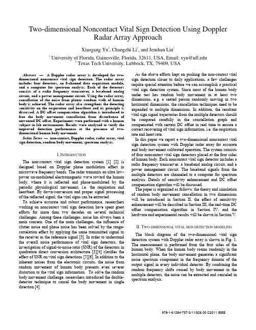
Index Term, radar array, vital sign detection, random body movement, spectrum analysis.
I. INTRODUCTION
The non-contact vital sign detection system [1] [2] is designed based on Doppler phase modulation effect in microwave frequency bands. The radar transmits an ultra lowpower un-modulated electromagnetic wave toward the human body, where it is reflected and phase-modulated by the periodic physiological movement, i.e. the respiration and heartbeat. By down-conversion and proper signal processing of the reflected signal, the vital signs can be extracted.
材料热力学——相图计算机计算

铝的晶格稳定性参数的确定
• 纯 铝 在 933.47K ( 610.43C) 以 下 为 FCC 结构,在610.43C以上为 液相。 • 铝与其它元素互溶还形成 稳定的Bcc_A2(如:Al-Fe) 与 Hcp_A3固溶体(如:AlMg) ,因此我们需要把纯 铝在这两种状态的自由能 表达式也求出来。
材料热力学:相图计算机计算
什么是相图计算?
• 相图计算就是运用热力学原理计算 系统的相平衡关系并绘制出相图的 科学研究。 • 相图计算的关键就是选择合适的热 力学模型模拟各相的热力学性质随 温度、压力、成分等的变化。
模型
• 模型就是一些有用的数学表达式,有的表 达式可能有确切的物理意义,有的可能是 没有确切物理意义的经验公式。但是实际 经验表明,有坚实物理基础的模型比没有 物理基础的经验模型通常更有用,运用这 样的模型我们可以对实测范围以外的地方 作出恰当的预测。
相图计算历史
J.J. Van Laar (1909)
Initiated binary phase diagram calculation 1908 Van: J.J. Van Laar, Z. Phys. Chem., 63, 216 (1908)).
J.L. Meijering (1950):
Extended the work of Van Laar to higher order systems 1950Mei: J.L. Meijering, Philips Res. Rep., 5, 333 (1950). 1957Mei: J.L. Meijering, Acta Metall., 5, 257 (1957). L. Kaufman (1970): Published a monograph entitled” Computer calculation of phase diagrams) 1970Kau: L. Kaufman and H. Bernstein, Computer calculation of phase diagrams, New York: Academic Press (1970). M. Hillert (1970): Introduced the sub-lattice model: 1970Hil: M. Hillert, L.-I. Staffansson: Acta Chem. Scand. 24, 3618 (1970).
气象泰勒图
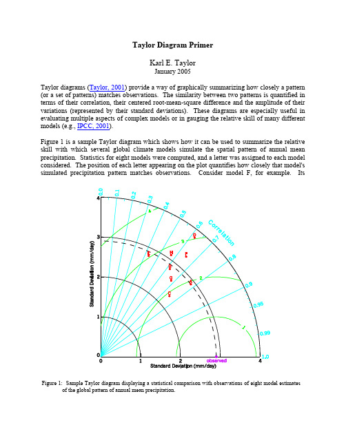
Taylor Diagram PrimerKarl E. TaylorJanuary 2005Taylor diagrams (Taylor, 2001) provide a way of graphically summarizing how closely a pattern (or a set of patterns) matches observations. The similarity between two patterns is quantified in terms of their correlation, their centered root-mean-square difference and the amplitude of their variations (represented by their standard deviations). These diagrams are especially useful in evaluating multiple aspects of complex models or in gauging the relative skill of many different models (e.g., IPCC, 2001).Figure 1 is a sample Taylor diagram which shows how it can be used to summarize the relative skill with which several global climate models simulate the spatial pattern of annual mean precipitation. Statistics for eight models were computed, and a letter was assigned to each model considered. The position of each letter appearing on the plot quantifies how closely that model's simulated precipitation pattern matches observations. Consider model F, for example. ItsFigure 1: Sample Taylor diagram displaying a statistical comparison with observations of eight model estimates of the global pattern of annual mean precipitation.pattern correlation with observations is about 0.65. The centered root-mean-square (RMS) difference between the simulated and observed patterns is proportional to the distance to the point on the x-axis identified as "observed." The green contours indicate the RMS values and it can be seen that in the case of model F the centered RMS error is about 2.6 mm/day. The standard deviation of the simulated pattern is proportional to the radial distance from the origin. For model F the standard deviation of the simulated field (about 3.3 mm/day) is clearly greater than the observed standard deviation which is indicated by the dashed arc at the observed value of 2.9 mm/day.The relative merits of various models can be inferred from figure 1. Simulated patterns that agree well with observations will lie nearest the point marked "observed" on the x-axis. These models will have relatively high correlation and low RMS errors. Models lying on the dashed arc will have the correct standard deviation (which indicates that the pattern variations are of the right amplitude). In figure 1 it can be seen that models A and C generally agree best with observations, each with about the same RMS error. Model A, however, has a slightly higher correlation with observations and has the same standard deviation as the observed, whereas model C has too little spatial variability (with a standard deviation of 2.3 mm/day compared to the observed value of 2.9 mm/day). Of the poorer performing models, model E has a low pattern correlation, while model D has variations that are much larger than observed, in both cases resulting in a relatively large (~3 mm/day) centered RMS error in the precipitation fields. Note also that although models D and B have about the same correlation with observations, model B simulates the amplitude of the variations (i.e., the standard deviation) much better than model D, and this results in a smaller RMS error.In general, the Taylor diagram characterizes the statistical relationship between two fields, a "test" field (often representing a field simulated by a model) and a "reference" field (usually representing “truth”, based on observations). Note that the means of the fields are subtracted out before computing their second-order statistics, so the diagram does not provide information about overall biases, but solely characterizes the centered pattern error.The reason that each point in the two-dimensional space of the Taylor diagram can represent three different statistics simultaneously (i.e., the centered RMS difference, the correlation, and the standard deviation) is that these statistics are related by the following formula:R E r f r f σσσσ2222−+=#,where R is the correlation coefficient between the test and reference fields, E' is the centered RMS difference between the fields, and σf 2 and σr 2 are the variances of the test and reference fields, respectively. (The formulas for calculating these second order statistics are provided at the end of this document.) The construction of the diagram (with the correlation given by the cosine of the azimuthal angle) is based on the similarity of the above equation and the Law of Cosines:φcos 2222ab b a c −+=There are several minor variations on the diagram that have been found useful for various purposes (see, Taylor, 2001). For example,• The diagram can be extended to a second "quadrant" (to the left) to allow for negative correlations.• The statistics can be normalized (and non-dimensionalized), dividing both the RMS difference and the standard deviation of the "test" field by the standard deviation of the observations. In this case the "observed" point is plotted on the x-axis at unit distance from the origin. This makes it possible to plot statistics for different fields (with different units) on the same plot.• The isolines drawn on the sample plot above are often omitted to make it easier to see the plotted points.• When comparing fields simulated by two different versions of a model, the two points on the graph representing those fields are often connected by an arrow to indicate more clearly whether or not the model is moving toward "truth," as defined by observations.Some sample diagrams are available here .Further notes:Given a "test" field (f ) and a reference field (r ), the formulas for calculating the correlation coefficient (R ), the centered RMS difference (E '), and the standard deviations of the "test" field (σf ) and the reference field (σr ) are given below:()()rf N n n n r r f f N R σσ∑=−−=11()()[]∑=−−−=#N n n n r r f f N E 1221()∑=−=N n n f f f N 1221σ()∑=−=N n n r r r N 1221σwhere the overall mean of a field is indicated by an overbar. In the case of a time-independent field, the sum is computed over all grid cells. For the typical spatial grid, the grid cell area is not uniform, so each grid cell must be weighted by the fraction of the total area represented by that grid cell. In the case of a time varying field, the sum is a double-sum computed over all grid cells and all time samples.References:Taylor, K.E.: Summarizing multiple aspects of model performance in a single diagram. J. Geophys. Res., 106, 7183-7192, 2001 (also see PCMDI Report 55, http://www-/publications/ab55.html)IPCC, 2001: Climate Change 2001: The Scientific Basis, Contribution of Working Group I to the Third Assessment Report of the Intergovernmental Panel on Climate Change [Houghton, J.T., Y. Ding, D.J. Griggs, M. Noguer, P.J. van der Linden, X. Dai, K. Maskell, and C.A.Johnson (eds.)]. Cambridge University Press, Cambridge, United Kingdom and NewYork, NY, USA, 881 pp. (see http://www.grida.no/climate/ipcc_tar/wg1/317.htm#fig84)。
一类三阶混沌系统的反馈控制实验设计
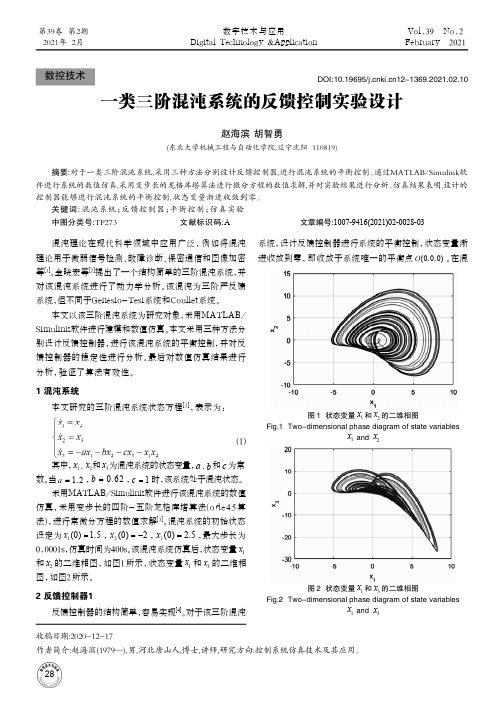
混沌理论在现代科学领域中应用广泛,例如将混沌理论用于微弱信号检测、故障诊断、保密通信和图像加密等[1]。
金晓宏等[2]提出了一个结构简单的三阶混沌系统,并对该混沌系统进行了动力学分析。
该混沌为三阶严反馈系统,但不同于Genesio-Tesi系统和Coullet系统。
本文以该三阶混沌系统为研究对象,采用MATLAB/Simulink软件进行建模和数值仿真。
本文采用三种方法分别设计反馈控制器,进行该混沌系统的平衡控制,并对反馈控制器的稳定性进行分析。
最后对数值仿真结果进行分析,验证了算法有效性。
1 混沌系统本文研究的三阶混沌系统状态方程[2],表示为:(1)其中,1x、2x和3x为混沌系统的状态变量,a、b和c为常数。
当 1.2a=,0.62b=,1c=时,该系统处于混沌状态。
采用MATLAB/Simulink软件进行该混沌系统的数值仿真,采用变步长的四阶-五阶龙格库塔算法(o de45算法),进行常微分方程的数值求解[3]。
混沌系统的初始状态设定为1(0) 1.5x=,2(0)2x=-,3(0) 2.5x=,最大步长为0.0001s,仿真时间为400s。
该混沌系统仿真后,状态变量1x和2x的二维相图,如图1所示,状态变量1x和3x的二维相图,如图2所示。
2 反馈控制器1反馈控制器的结构简单,容易实现[4]。
对于该三阶混沌系统,设计反馈控制器进行系统的平衡控制,状态变量渐进收敛到零,即收敛于系统唯一的平衡点(0,0,0)O。
在混收稿日期:2020-12-17作者简介:赵海滨(1979—),男,河北唐山人,博士,讲师,研究方向:控制系统仿真技术及其应用。
一类三阶混沌系统的反馈控制实验设计赵海滨 胡智勇(东北大学机械工程与自动化学院,辽宁沈阳 110819)摘要:对于一类三阶混沌系统,采用三种方法分别设计反馈控制器,进行混沌系统的平衡控制。
通过MATLAB/Simulink软件进行系统的数值仿真,采用变步长的龙格库塔算法进行微分方程的数值求解,并对实验结果进行分析。
二维光栅位移测量技术综述

第6期
尹云飞, 等: 二维光栅位移测量技术综述
1225
ing, but also plays a decisive role in the chip manufacturing industry that is rapidly developing in Moore's Law. The grating displacement measurement system based on the grating pitch is widely used in multidimensional measurement system. Compared with the laser displacement measurement system, grating displacement measurement system greatly reduces the environmental requirements for humidity, temperature and pressure. In this paper, the development status of the optical structure of displacement sensing system based on two-dimensional grating in recent years is introduced. The principles of zero-difference and heterodyne grating interferometrys are introduced. The optical structure based on single-block two-dimensional grating is reviewed. The development history of the optical structure in single-block two-dimensional grating to coupling designs of multi-block two-dimensional gratings is summarized, the advantages and disadvantages of several two-dimensional grating displacement measurement systems are compared and analyzed, and the development trend of two-dimensional grating displacement measurement system is prospected. The engineering process of two-dimensional grating displacement measurement system is summarized. Key words: two-dimensional grating;grating interference technique;precision displacement measurement
- 1、下载文档前请自行甄别文档内容的完整性,平台不提供额外的编辑、内容补充、找答案等附加服务。
- 2、"仅部分预览"的文档,不可在线预览部分如存在完整性等问题,可反馈申请退款(可完整预览的文档不适用该条件!)。
- 3、如文档侵犯您的权益,请联系客服反馈,我们会尽快为您处理(人工客服工作时间:9:00-18:30)。
ar Xiv:c on d -m a t/9609031v 13 S e p1996Phase Diagram of the Two Dimensional Lattice Coulomb GasPramod Gupta and S.TeitelDepartment of Physics and Astronomy,University of Rochester,Rochester,New York 14627(February 1,2008)We use Monte Carlo simulations to map out the phase diagram of the two dimensional Coulomb gas on a square lattice,as a function of density ρand temperature T.We find that the Kosterlitz-Thouless transition remains up to higher charge densities than has been suggested by recent theo-retical estimates.The nature of phase transitions in the two dimensionalneutral Coulomb gas (CG)has remained a topic of con-siderable interest.The CG can be related via dualitytransformation to the 2D XY model,and thus to super-fluid and superconducting films.1The pioneering workof Kosterlitz and Thouless 2(KT)showed that,at low charge density,there is a second order transition from aninsulating to a conducting phase,due to the unbinding ofneutral charge pairs.As the charge density is increased,several authors 3–6have predicted that this KT transitionshould become first order.Recently,Levin et al.5,usinga modified Debye-H¨u ckel approach,have estimated that,for a continuum CG,the KT transition ends in a tricriti-cal point at the surprisingly low density of ρc ≃0.004/a 2,where a is the hard core diameter of the charges.To investigate this issue,we report here on new MonteCarlo simulations of the 2D CG on a square lattice,com-puting the phase diagram as a function of density andtemperature.We make sensitive tests of the nature ofthe transition,and conclude that it remains second order up to densities much higher than estimated by Levin etal.Our work follows that of Lee and Teitel,7with a fewmodifications.We take for the Hamiltonian,H =1L +V 2πP y2ln(8e 2γ),where γ≃0.5772is Euler’s constant.2,8n i =0,±1,±2...are the integer charges,and neutralityi n i =0is imposed.The third termin H tends to suppress charges with |n i |>1,and isneeded to stabilize the system in the very dense limit.Assuming therefore that all charges satisfy |n i |≤1,so that |n i |=n 2i ,the second term is just −uρL 2withρ=L −2i |n i |the charge density.Thus u is the chem-ical potential.The last two terms in H are effectiveboundary terms,which arise in the duality mapping tothe CG fromthe 2D XY model with periodic boundary conditions.9–11Here P ≡i n i r i is the net dipole mo-ment of the charges,and V (φ)is the Villain function,12e −V(φ)/T ≡ ∞m=−∞e −1L δµν−2πL V ′ 2πP ν0.20.40.60.81.01.2T r i c r i t i c a l P o i n t I s i n g (M e l t i n g )K T c h a r g e d e n s i t y ρI n s u l a t i n g S o l i d C o n d u c t i n g S o l i d I n s u l a t i n g G a s C o n d u c t i n g L i q u i d P h a s e S e p a r a t e d R e g i o n FIG.2.Phase diagram of the lattice CG in the ρ−T plane.Open symbols are from simulations with system size L =16;solid symbols are from L =32.0.0000.0020.0040.0060.0080.0100.0120.0140.30.40.50.60.70.80.91.0P r o b a b i l i t y P (ρ)T = 0.142T = 0.139T = 0.137L = 32 u = 0.4 > u 0L i q u i d C o e x i s t e n c e S o l i d FIG.3.Histograms of charge density ρfor u =0.4just above u 0=π/8.At the coexistence boundary the histogram is bimodalobtained by simulating with u just above and just below u 0,measuring the average density ρas T increases.To determine the boundary closer to the tricritical point,we simulate with fixed u >u 0,increasing T ,and measuring the histogram of the values of ρfound at each value of T .When one is in either the solid or the liquid phase,this histogram has a single peak.However,when one crosses the first order line,this histogram develops double peaks.15The locations of the two peaks determine the densities of the two coexisting phases.In Fig.3we show an example of such histograms.Varying u >u 0then maps out the rest of the coexistence boundary.In Fig.2we show the coexistence boundary found in this way from simulations with L =16and L =32.As is seen,and as is expected,our results near the tricritical point are limited by finite size effects.However it is clear that the KT line at small u joins the first order line at a density ρ≃0.1,much larger than the estimate of Levin et al.Next we verify that what we have called the “KT”line at small u actually does remain a second order KT transition all the way up to the first order line separating the insulating gas and insulating solid.To locate the transition temperature T ∗for u =0.39,just below u 0,we compute ǫ−1(T )for various L ,using Eq.(2).Our results are shown in Fig.4.The intersection of these curves with the line 4T determines the upper bound T ∗≃0.125.No hysteresis,or other suggestion of a first order transition 0.20.30.40.50.60.70.80.90.1180.1220.1260.130L =64L =32L =16L =8in v e r s e d i e l e c t r i c c o n s t a n t u = 0.39 < u 0 = 0.392699ε−14T FIG.4.Inverse dielectric function ǫ−1(T )for various lattice sizes L ,for u =0.39just below u 0=π/8.The intersection with the line 4T gives the KT upper bound on the transition temperature T ∗.was observed in ǫ−1.As a more precise test that the transition is indeed KT–like,we use the finite size scaling procedure of We-ber and Minnhagen 16,17.Precisely at the KT transition temperature,the finite size dependence of ǫ−1is given by,ǫ−1(L )=ǫ−1(∞) 1+10102030400.1200.1210.1220.1230.1240.1250.126χ2offit toE q.(3)u=0.39 < u 0(a)3.54.04.55.00.1200.1210.1220.1230.1240.1250.126L=8,12,16,24,32,48,64L=12,16,24,32,48,64L=16,24,32,48,64fit te dv alueofε-1(∞)/T Temperature Tuniversal KT criterion(b)T *FIG.5.Fitting of ǫ−1(T,L )to Eq.(3).(a )shows the χ2of the fit vs.T ,(b )shows the value of the fitted ǫ−1(∞)/T vs.T .0.0000.0050.0100.0150.0200.0250.0300.000.050.100.150.200.25P r o b a b i l i t y P (ρ)L = 64 u = 0.39 < u 0T =0.110T =0.115T =0.120T =0.125T =0.127T =0.130FIG.6.Histograms of charge density ρfor u =0.39just below u 0=π/8.Histograms remain single peaked as one passes though the transition at T ∗≃0.1235of excited isolated dipoles and quadrupoles.For the lower branch we get ρ−(T )=1L 2(2N ′d e −βE ′d +4N ′q e −βE ′q )where E ′d and E ′q are the energies for removing an isolated dipole and quadrupole,and N ′d =2L 2and N ′q =L 2are the number of ways this may be done.Clearly these expressions will change with the geometry of the discretizing lattice,or if a continuum is used.Nevertheless,at the very low den-sities ρ∼0.004and high temperatures T ≃0.25where Levin et al.estimate a tricritical point,we would be very surprised if the lattice is qualitatively different from the ing a discrete lattice also has the effect that it tends to stabilize the charge solid phase above u 0to high tem-peratures.Indeed,our charge solid only melts after it has already become conducting via a KT transition arising from the excitation and diffusion of vacancies through-out the solid.The present model does not possess any first order transition from an insulating to a conduct-ing phase.In contrast,recent simulations 18,19of the CG in a flat continuum with periodic boundary conditions find that the charge solid phase is melted at any finite temperature.Here,a first order line separates the in-sulating gas from a dense conducting liquid,ending at a critical point at relatively low temperature and high density:(T c ,ρc )=(0.056,0.21)according to Ref.18,and T c =0.032according to Ref.19.Similar results were found earlier for the continuum CG on the surface of a sphere:20(T c ,ρc )=(0.087,0.11).In these models,the KT line ends either at,or near this critical point.Although the geometry of the the CG system clearly affects the location of the end of the KT transition line,it is interesting to compare our results for the square lat-tice with the predictions of the continuum self-consistent screening theory of Minnhagen and Wallin.3To do so,it is necessary to note 2,8that if the interaction G ( r )on the lattice is chosen so as to asymptotically match the continuum −ln r as r →∞,then the lattice CG with u =0acts like a continuum model with a chemical potential µ0=−1。