英飞凌单片机例程tc1767_taskingv33r2_flash
英飞凌单片机例程tc1767_taskingv33r2_spram

Note: DAvE doesn‟t change code that is inserted in the „USER CODE‟ sections if you let DAvE regenerate code. Therefore, whenever adding code to the generated code, write it into a „USER CODE‟ section. If you want to change DAvE generated code or add code outside these „USER CODE‟ sections you have to modify your changes after each time you let DAvE regenerate code!
confidential
Page 15
Exercise MEM_2 Tasking Viper : Change Link script file
Select MEM_2.lsl file and unlock the Memory Change the ROM setting
Change the type of SPRAM to ROM
confidential
Page 6
Exercise MEM_2 Tasking Viper : Start Viper
Start TASKING VX-toolset for tricore Click on Open Project Work Space Filename: browse to “d:\hot\tc1767” Click „OK‟
1
confidential
英飞凌单片机例程tc1767_taskingv34r1_can_1
Exercise CAN_1 DAvE Configurations (cont.)
Configure ASC0 (cont.) Pin selection / ASC0_RX and ASC0_TX:
Use Pin P3.0 as ASC0 receive signal. Use Pin P3.1 as ASC0 transmit signal.
Click here
confidential
Page 8
Exercise CAN_1 DAvE Configurations (cont.)
Configure ASC0 Module Clock:
Enable ASC0 module. Module clock: 40MHz.
confidential
Project Settings (cont.) MultiCAN / List
Drag MO 000 to Node 0 Drag M2 000 to Node 1
Drag from list on left
confidential
Page 26
Exercise CAN_1 DAvE Configurations (cont.)
confidercise CAN_1 DAvE Configurations (cont.)
Configure ASC0 (cont.) Baud Rate :
Required Baud rate: 19200 Baud.
confidential
Page 13
Exercise CAN_1 DAvE Configurations (cont.)
Configure ASC0 (cont.) Interrupts :
Infineon(英飞凌)单片机教案PPT

XC167CI单片机特性
8KB/12 KB片上RAM 128 KB/256 KB程序Flash存储器 16通道10位数模转换器,转换时间< 3 µs 各带两个独立时间基准的两个16通道捕获/比 较单元 带有两个独立定时器的CAPCOM6模块,产生用 于交流和直流电机控制的PWM信号 10位寻址,400 kbit/s的I² C总线模块
9针RS-232 串口( ) 1--CD载波侦测( Carrier DetectDB9 ) 2 -- RXD接收数据(Receive) 3 -- TXD发送数据(Transmit) 4 -- DTR数据终端准备(Data Terminal Ready) 5 -- GND地线(Ground) 6 -- DSR数据准备好(Data Set Ready) 7 -- RTS请求发送(Request To Send) 8 -- CTS清除发送(Clear To Send) 9 -- RI振铃指示(Ring Indicator)
微型计算机的组成框图 (由多个IC芯片组装在一个主电路板上)
所有单元都组装 在一个IC芯片上
Infineon单片机分类
根据每种型号的存储器的类型分类
无ROM型:C167CR-LM ROM型 :C167CR-16RM OTP型 :C164CI-8EM FLASH型 :XC167CI-32F
JTAG引脚说明
TCK为测试时钟输入 TDI为测试数据输入 TDO为测试数据输出 TMS为测试模式选择 /TRST为测试复位,输入引脚,低电平有效。
启动模式选择
模式开关说明
启动模式说明
英飞凌单片机例程tc1767_taskingv33r2_introduction

Note : You may have to reboot your computer at the end of the installation.
Note: the Infineon DAS servers are automatically installed together with Tasking‟s tool chain.
Context Sensitive Help provides complete command syntax and detailed description with hypertext links to the user manual.
More information is available at
For internal use only Page 5
Introduction to the Tasking Viper for Tricore
Assembler: The BSO/TASKING assembler is an integral part of the tool set but delivers features that enable it to be used on its own. It is supplied complete with linker/locator, librarian and object format utilities. Linker/Locator: The linker and locator is an essential part of the software building process that enables you to link and locate modules in target memory. More information is available at
英飞凌单片机例程tc1767_taskingv33r2_pwm_ltc

confidential
Page 17
Exercise GPTA_LTC_PWM DAvE Configurations (cont.)
GPTA0 Local Timer Cell /LTC4/LTC4:
Enable LTC4 after initialization. Mode: Compare with Last Timer. LTC4 register value : 0x05DB. Reset the LTC4 output by a local event or copy previous cell action. LTC4mode control: Enable high level of „Select Line Input‟.
Page 19
Exercise GPTA_LTC_PWM DAvE Configurations (cont.)
GPTA0 Output Pins:
Click on “OUT1”.
confidential
Page 20
Exercise GPTA_LTC_PWM DAvE Configurations (cont.)
confidential
Page 4
Exercise GPTA_LTC_PWM PWM Signal Update (Coherent)
Timer
0 Compare_0(Period) 0 1 Compare_1(Period) 0 1
Reset timer
-1
Compare_0(Duty) Compare_1(Duty)
Select “GPTA0_vInit”.
confidential
Page 22
51单片机电机三档调速程序

/*******************************************一键三档风扇程序 2022年8月28日******************************************/#include<reg52.h> //包含52单片机寄存器定义的头文件#include<intrins.h>unsigned char Tab[ ]={0xc0,0xf9,0xa4,0xb0,0x99,0x92,0x82,0xf8,0x80,0x90}; //段码表sbit ON_OFF=P3^2;//开关定义sbit motor=P3^5;//马达控制脚sbit dis=P3^4;int i=0;//档位标志void delay1ms(unsigned int i) //1ms延时程序{unsigned int j;for(;i>0;i--)for(j=0;j<125;j++){;}}/******************************************************************函数功能:延时约0.6ms********************************************************************/void delay(void){unsigned char j;for(j=0;j<200;j++);}void settinglow(){motor=0;_nop_();_nop_();_nop_();_nop_();_nop_();_nop_();_nop_();motor=1;}/****************************************************************** 函数功能:显示计数次数的子程序入口参数:i********************************************************************/ void Display(unsigned char i){dis=0; //P3.4引脚输出低电平,数码管点亮P1=Tab[i%10]; //显示个位delay();dis=1;P1=0xff;delay();}/*******************************************函数功能:主函数******************************************/void main(void){EA=1; //开放总中断EX0=1; //允许使用外中断IT0=1; //选择负跳变来触发外中断i=0;motor=0;while(1){if(i>0){Display(i);}switch(i){case 0:motor=0;break;case 1:motor=1;break;case 2:settinglow();break;case 3:motor=~motor;break;}}}/************************************************************** 函数功能:外中断T0的中断服务程序**************************************************************/ void it0(void) interrupt 0 using 0 //外中断0的中断编号为0{if(ON_OFF==0){delay1ms(50);if(ON_OFF==0){i++;//按一次开关键,改变一个档位}}if(ON_OFF==0){delay1ms(1000);//长按1秒则关闭风扇if(ON_OFF==0){i=0;}}if(i==4)//最慢档后再按一次到最快档{i=1;}}。
英飞凌16_32位单片机一级JTAG连接引脚配置
Application Note
5
V2.2.1, 2003-07
AP24001 OCDS Level1 JTAG Connector
Low Cost EVA Board Connector
4
Low Cost EVA Board Connector
The Infineon StarterKit boards are equipped with a low cost DB25 printer port connector. The JTAG Signals are mapped to the following Printer-Port signals. It is not recommended to use a DB25 connector in customer applications since the onboardwiggler would eat up additional board space & power.
Controller Area Network (CAN): License of Robert Bosch GmbH
We Listen to Your Comments Is there any information in this document that you feel is wrong, unclear or missing? Your feedback will help us to continuously improve the quality of our documentation. Please send your comments (including a reference to this document) to: ipdoc@
sonix单片机硬件电路设计实例(工程师多年经验总结)教学教材

s o n i x单片机硬件电路设计实例(工程师多年经验总结)单片机产品设计--功能评估1,先得了解MCU 的功能及每一个管脚的做用(输入口还是输出口或双向口或是其他特殊端口),确定用什么样的电源输入(变压器或阻容降压),有无大电流负载及一些安规方面的要求,体积封装大小有无规定。
2,采用电池供电时是否要考虑做一些省电低功耗线路。
3,带检测功能的产品是否用到A/D功能,有无必要用到一些精密参考源,主要针对测量及充电电路,或是可否直接采用RC充放电线路来做模拟量检测, A/D通道转换需要一定的稳定时间,在软件设计时需要作考量。
为了保证每次A/D转换的稳定与正确,最好在每次A/D转换前都重新确定A/D转换通道、A/D转换分辨率、A/D时钟源选择位,而且根据所应用场合对所取得数据进行合理的处理。
A/D转换在硬件设计方面的注意事项:信号源要尽量与A/D转换输入端接近,而且要视芯片输入阻抗添加合适的电容并入信号源输入端。
此外需保证A/D转换基准电压的稳定,模拟地与数字地要分开或隔离。
4,操作时有多少个按键,能否采用跟其他I/O口复用来节少I/O口资源,按键是否要采用唤醒功能,即采用带有唤醒功能的I/O口,按键输入可否采用矩阵扫描,以便节省单片机的I/O口。
5,输出指示能否跟输出控制I/O口复用,这样也可以节省I/O口,但要考虑到输出电流的大小,不能影响负载的正常输出控制。
6,有无精确度要求较高的定时,用来确定采用什么样的振荡源( 晶振,陶振,外部RC及MCU内部RC)。
7,复位电路的选取,I/O口不够时能否采用内部复位, 芯片的上电复位时间与系统电压上升速度,外部振荡器频率、种类及外部Reset 电路造成的delay都有关联。
8,有无显示电路,是LED还是LCD,是否必要采用外挂驱动电路或直接采用I/O口推动,一般采用I/O口推动的 LCD,com口都采用1/2 偏压。
直接用两电阻分压。
9,大电流负载输出采用mos管,继电器还是可控硅控制?当输出为可控硅时,是否采用共地或共电源控制,或是用直接耦合还是用光电耦合,同时得考虑是否要用到到同步信号做一些调速、调光、调功率、调温度等可调的控制功能(同时些交流同步信号也可以做一些定时产品的参考)。
单片机实验:正弦波和三角波程序
正弦波//-----------------------------------------------------------------------------// F41x_DACs_SineCosine.c//-----------------------------------------------------------------------------// Copyright 2006 Silicon Laboratories, Inc.// //// Program Description://// This program outputs sine and cosine waveforms using the hardware DACs// on the C8051F410 microcontroller. The waveforms are output on pins// P0.0/IDA0 and P0.1/IDA1.//// The output of the DACs is updated upon a Timer3 interrupt. The Timer3 ISR // then calculates the output of the DACs for the next interrupt.//// The frequency of the output waveforms is set by the #define <FREQUENCY>. ////// How To Test://// 1) Download the code to an C8051F410 Development Board// 2) Check that the J6 and J16 shorting blocks are not installed. This// ensures that the IDAC outputs are not connected to any other pins// 3) Check that the J13 and J14 short blocks are installed. This connects// the DAC outputs to resistors so that the output current is converted// to a voltage// 4) Connect two oscillscope probes to pins P0.0/IDA0 and P0.1/IDA1.// These pins are available on both the J2 and J11 headers.// 5) Confirm that there are two waveforms with the output of DAC1 leading// the output DAC0 by 90 degrees. The frequency of both waveforms should // be close to frequency defined by <FREQUENCY>//// FID: 41X000036// Target: C8051F41x// Tool chain: Keil C51 7.50 / Keil EV AL C51// Silicon Laboratories IDE version 2.71// Command Line: Default//// Release 1.0// -Initial Revision (GP)// -09 AUG 2006////-----------------------------------------------------------------------------// Includes//-----------------------------------------------------------------------------#include <c8051f410.h> // SFR declarations//-----------------------------------------------------------------------------// 16-bit SFR Definitions for 'F41x//-----------------------------------------------------------------------------sfr16 TMR3RL = 0x92; // Timer3 reload valuesfr16 TMR3 = 0x94; // Timer3 countersfr16 IDA0 = 0x96; // IDA0 high and low bytessfr16 IDA1 = 0xF4; // IDA1 high and low bytes//-----------------------------------------------------------------------------// Global Constants//-----------------------------------------------------------------------------#define SYSCLK 24500000 // Internal oscillator frequency in Hz#define SAMPLE_RATE_DAC 100000L // DAC sampling rate in Hz#define PHASE_PRECISION 65536 // range of phase accumulator#define FREQUENCY 1000 // Frequency of output waveform in Hz// <PHASE_ADD> is the change in phase between DAC samples; It is used in// the set_DACs routine.unsigned int PHASE_ADD = FREQUENCY * PHASE_PRECISION / SAMPLE_RA TE_DAC;int code SINE_TABLE[256] ={0x0000, 0x0324, 0x0647, 0x096a, 0x0c8b, 0x0fab, 0x12c8, 0x15e2,0x18f8, 0x1c0b, 0x1f19, 0x2223, 0x2528, 0x2826, 0x2b1f, 0x2e11,0x30fb, 0x33de, 0x36ba, 0x398c, 0x3c56, 0x3f17, 0x41ce, 0x447a,0x471c, 0x49b4, 0x4c3f, 0x4ebf, 0x5133, 0x539b, 0x55f5, 0x5842,0x5a82, 0x5cb4, 0x5ed7, 0x60ec, 0x62f2, 0x64e8, 0x66cf, 0x68a6,0x6a6d, 0x6c24, 0x6dca, 0x6f5f, 0x70e2, 0x7255, 0x73b5, 0x7504,0x7641, 0x776c, 0x7884, 0x798a, 0x7a7d, 0x7b5d, 0x7c29, 0x7ce3,0x7d8a, 0x7e1d, 0x7e9d, 0x7f09, 0x7f62, 0x7fa7, 0x7fd8, 0x7ff6,0x7fff, 0x7ff6, 0x7fd8, 0x7fa7, 0x7f62, 0x7f09, 0x7e9d, 0x7e1d,0x7d8a, 0x7ce3, 0x7c29, 0x7b5d, 0x7a7d, 0x798a, 0x7884, 0x776c, 0x7641, 0x7504, 0x73b5, 0x7255, 0x70e2, 0x6f5f, 0x6dca, 0x6c24, 0x6a6d, 0x68a6, 0x66cf, 0x64e8, 0x62f2, 0x60ec, 0x5ed7, 0x5cb4, 0x5a82, 0x5842, 0x55f5, 0x539b, 0x5133, 0x4ebf, 0x4c3f, 0x49b4, 0x471c, 0x447a, 0x41ce, 0x3f17, 0x3c56, 0x398c, 0x36ba, 0x33de, 0x30fb, 0x2e11, 0x2b1f, 0x2826, 0x2528, 0x2223, 0x1f19, 0x1c0b, 0x18f8, 0x15e2, 0x12c8, 0x0fab, 0x0c8b, 0x096a, 0x0647, 0x0324,0x0000, 0xfcdc, 0xf9b9, 0xf696, 0xf375, 0xf055, 0xed38, 0xea1e, 0xe708, 0xe3f5, 0xe0e7, 0xdddd, 0xdad8, 0xd7da, 0xd4e1, 0xd1ef, 0xcf05, 0xcc22, 0xc946, 0xc674, 0xc3aa, 0xc0e9, 0xbe32, 0xbb86, 0xb8e4, 0xb64c, 0xb3c1, 0xb141, 0xaecd, 0xac65, 0xaa0b, 0xa7be, 0xa57e, 0xa34c, 0xa129, 0x9f14, 0x9d0e, 0x9b18, 0x9931, 0x975a, 0x9593, 0x93dc, 0x9236, 0x90a1, 0x8f1e, 0x8dab, 0x8c4b, 0x8afc, 0x89bf, 0x8894, 0x877c, 0x8676, 0x8583, 0x84a3, 0x83d7, 0x831d, 0x8276, 0x81e3, 0x8163, 0x80f7, 0x809e, 0x8059, 0x8028, 0x800a, 0x8000, 0x800a, 0x8028, 0x8059, 0x809e, 0x80f7, 0x8163, 0x81e3, 0x8276, 0x831d, 0x83d7, 0x84a3, 0x8583, 0x8676, 0x877c, 0x8894, 0x89bf, 0x8afc, 0x8c4b, 0x8dab, 0x8f1e, 0x90a1, 0x9236, 0x93dc, 0x9593, 0x975a, 0x9931, 0x9b18, 0x9d0e, 0x9f14, 0xa129, 0xa34c, 0xa57e, 0xa7be, 0xaa0b, 0xac65, 0xaecd, 0xb141, 0xb3c1, 0xb64c, 0xb8e4, 0xbb86, 0xbe32, 0xc0e9, 0xc3aa, 0xc674, 0xc946, 0xcc22, 0xcf05, 0xd1ef, 0xd4e1, 0xd7da, 0xdad8, 0xdddd, 0xe0e7, 0xe3f5, 0xe708, 0xea1e, 0xed38, 0xf055, 0xf375, 0xf696, 0xf9b9, 0xfcdc, };//-----------------------------------------------------------------------------// Function Prototypes//-----------------------------------------------------------------------------void main(void);void OSCILLATOR_Init (void);void PORT_Init (void);void DAC0_Init (void);void DAC1_Init (void);void TIMER3_Init (int counts);void Set_DACs (void);//-----------------------------------------------------------------------------// MAIN Routine//-----------------------------------------------------------------------------void main (void){PCA0MD &= ~0x40; // Disable Watchdog timerOSCILLATOR_Init (); // Initialize oscillatorPORT_Init (); // Initialize crossbar and portsDAC0_Init (); // Initialize DAC0DAC1_Init (); // Initialize DAC1TIMER3_Init(SYSCLK/SAMPLE_RA TE_DAC);// Initialize Timer3 to overflow at// <SAMPLE_RATE_DAC> times per second EA = 1; // Enable global interruptswhile(1) {} // Wait for interrupt}//-----------------------------------------------------------------------------// Interrupt Service Routines//-----------------------------------------------------------------------------//-----------------------------------------------------------------------------// TIMER3_ISR//-----------------------------------------------------------------------------//// This ISR is called on Timer3 overflows. Timer3 is set to auto-reload mode// and is used to schedule the DAC output sample rate in this example.// Note that the values written to the DACs during this ISR call are// actually transferred to the DACs at the next Timer3 overflow.////-----------------------------------------------------------------------------void TIMER3_ISR (void) interrupt 14{TMR3CN &= ~0x80; // Clear Timer3 overflow flagSet_DACs();}//-----------------------------------------------------------------------------// Initialization Routines//-----------------------------------------------------------------------------//-----------------------------------------------------------------------------// OSCILLATOR_Init//-----------------------------------------------------------------------------//// Return Value : None// Parameters : None//// This routine initializes the system clock to use the internal 24.5MHz// oscillator as its clock source. Also enables missing clock detector reset.////-----------------------------------------------------------------------------void OSCILLATOR_Init (void){OSCICN = 0x87; // Set clock to 24.5 MHzRSTSRC = 0x04; // Enable missing clock detector}//-----------------------------------------------------------------------------// PORT_Init//-----------------------------------------------------------------------------//// Return Value : None// Parameters : None//// This routine initializes the IDAC pins and enables the crossbar.//// P0.0 analog IDA0// P0.1 analog IDA1////-----------------------------------------------------------------------------void PORT_Init (void){P0MDIN = 0xFC; // Configure P0.0 and P0.1 to analog P0SKIP = 0x03; // Skip P0.0 and P0.1 on the crossbar XBR1 = 0x40; // Enable Crossbar}//-----------------------------------------------------------------------------// DAC0_Init//-----------------------------------------------------------------------------//// Return Value : None// Parameters : None//// Configure DAC0 to update on Timer3 overflows and enable VDD as VREF////-----------------------------------------------------------------------------void DAC0_Init(void){REF0CN = 0x0A; // Enable VDD as VREFIDA0CN = 0xB0; // Enable IDA0 for 2.0 mA output// left-justified// updated on Timer3 overflows}//-----------------------------------------------------------------------------// DAC1_Init//-----------------------------------------------------------------------------//// Return Value : None// Parameters : None//// Configure DAC1 to update on Timer3 overflows and disable the the VREF buffer ////-----------------------------------------------------------------------------void DAC1_Init(void){REF0CN = 0x0A; // Enable VDD as VREFIDA1CN = 0xB0; // Enable IDA0 for 2.0 mA output// left-justified// updated on Timer3 overflows}//-----------------------------------------------------------------------------// TIMER3_Init//-----------------------------------------------------------------------------//// Return Value : None// Parameters :// 1) int counts - calculated Timer overflow rate// range is positive range of integer: 0 to 32767//// Configure Timer3 to auto-reload at interval specified by <counts> using// SYSCLK as its time base.////-----------------------------------------------------------------------------void TIMER3_Init (int counts){TMR3CN = 0x00; // Resets Timer3,// Sets to 16 bit mode CKCON |= 0x40; // Use system clockTMR3RL = -counts; // Initial reload valueTMR3 = 0xffff; // Sets timer to reload automatically EIE1 |= 0x80; // Enable Timer3 interruptsTMR3CN = 0x04; // Start Timer3}//-----------------------------------------------------------------------------// Support Routines//-----------------------------------------------------------------------------//-----------------------------------------------------------------------------// Set_DACs//-----------------------------------------------------------------------------//// Return Value : None// Parameters : None//// Calculates the update values for the two DACs using SINE_TABLE. The DACs // will actually be updated upon the next Timer3 interrupt. Until that time,// the DACs will hold their current value.////-----------------------------------------------------------------------------void Set_DACs(void){static unsigned phase_acc = 0; // Holds phase accumulatorint SIN_temp, COS_temp; // Temporary 16-bit variablesunsigned char index; // Index into SINE tablephase_acc += PHASE_ADD; // Increment phase accumulator index = phase_acc >> 8;SIN_temp = SINE_TABLE[index]; // Read the table valueindex += 64; // 90 degree phase shiftCOS_temp = SINE_TABLE[index];// Add a DC bias to change the the rails from a bipolar (-32768 to 32767)// to unipolar (0 to 65535)// Note: the XOR with 0x8000 translates the bipolar quantity into// a unipolar quantity.IDA0 = SIN_temp ^ 0x8000; // Update DAC valuesIDA1 = COS_temp ^ 0x8000;}//-----------------------------------------------------------------------------// End Of File//-----------------------------------------------------------------------------大的正弦波//-----------------------------------------------------------------------------// F41x_DACs_SineCosine.c//-----------------------------------------------------------------------------// Copyright 2006 Silicon Laboratories, Inc.// //// Program Description://// This program outputs sine and cosine waveforms using the hardware DACs// on the C8051F410 microcontroller. The waveforms are output on pins// P0.0/IDA0 and P0.1/IDA1.//// The output of the DACs is updated upon a Timer3 interrupt. The Timer3 ISR // then calculates the output of the DACs for the next interrupt.//// The frequency of the output waveforms is set by the #define <FREQUENCY>. ////// How To Test://// 1) Download the code to an C8051F410 Development Board// 2) Check that the J6 and J16 shorting blocks are not installed. This// ensures that the IDAC outputs are not connected to any other pins// 3) Check that the J13 and J14 short blocks are installed. This connects// the DAC outputs to resistors so that the output current is converted// to a voltage// 4) Connect two oscillscope probes to pins P0.0/IDA0 and P0.1/IDA1.// These pins are available on both the J2 and J11 headers.// 5) Confirm that there are two waveforms with the output of DAC1 leading// the output DAC0 by 90 degrees. The frequency of both waveforms should // be close to frequency defined by <FREQUENCY>// FID: 41X000036// Target: C8051F41x// Tool chain: Keil C51 7.50 / Keil EV AL C51// Silicon Laboratories IDE version 2.71// Command Line: Default//// Release 1.0// -Initial Revision (GP)// -09 AUG 2006////-----------------------------------------------------------------------------// Includes//-----------------------------------------------------------------------------#include <c8051f410.h> // SFR declarations//-----------------------------------------------------------------------------// 16-bit SFR Definitions for 'F41x//-----------------------------------------------------------------------------sfr16 TMR3RL = 0x92; // Timer3 reload valuesfr16 TMR3 = 0x94; // Timer3 countersfr16 IDA0 = 0x96; // IDA0 high and low bytessfr16 IDA1 = 0xF4; // IDA1 high and low bytes//-----------------------------------------------------------------------------// Global Constants//-----------------------------------------------------------------------------#define SYSCLK 24500000 // Internal oscillator frequency in Hz#define SAMPLE_RATE_DAC 100000L // DAC sampling rate in Hz#define PHASE_PRECISION 65536 // range of phase accumulator#define FREQUENCY 1000 // Frequency of output waveform in Hz// <PHASE_ADD> is the change in phase between DAC samples; It is used in// the set_DACs routine.unsigned int PHASE_ADD = FREQUENCY * PHASE_PRECISION / SAMPLE_RA TE_DAC; int code SINE_TABLE[256] =0x0000, 0x0324, 0x0647, 0x096a, 0x0c8b, 0x0fab, 0x12c8, 0x15e2, 0x18f8, 0x1c0b, 0x1f19, 0x2223, 0x2528, 0x2826, 0x2b1f, 0x2e11, 0x30fb, 0x33de, 0x36ba, 0x398c, 0x3c56, 0x3f17, 0x41ce, 0x447a, 0x471c, 0x49b4, 0x4c3f, 0x4ebf, 0x5133, 0x539b, 0x55f5, 0x5842, 0x5a82, 0x5cb4, 0x5ed7, 0x60ec, 0x62f2, 0x64e8, 0x66cf, 0x68a6, 0x6a6d, 0x6c24, 0x6dca, 0x6f5f, 0x70e2, 0x7255, 0x73b5, 0x7504, 0x7641, 0x776c, 0x7884, 0x798a, 0x7a7d, 0x7b5d, 0x7c29, 0x7ce3, 0x7d8a, 0x7e1d, 0x7e9d, 0x7f09, 0x7f62, 0x7fa7, 0x7fd8, 0x7ff6, 0x7fff, 0x7ff6, 0x7fd8, 0x7fa7, 0x7f62, 0x7f09, 0x7e9d, 0x7e1d,0x7d8a, 0x7ce3, 0x7c29, 0x7b5d, 0x7a7d, 0x798a, 0x7884, 0x776c, 0x7641, 0x7504, 0x73b5, 0x7255, 0x70e2, 0x6f5f, 0x6dca, 0x6c24, 0x6a6d, 0x68a6, 0x66cf, 0x64e8, 0x62f2, 0x60ec, 0x5ed7, 0x5cb4, 0x5a82, 0x5842, 0x55f5, 0x539b, 0x5133, 0x4ebf, 0x4c3f, 0x49b4, 0x471c, 0x447a, 0x41ce, 0x3f17, 0x3c56, 0x398c, 0x36ba, 0x33de, 0x30fb, 0x2e11, 0x2b1f, 0x2826, 0x2528, 0x2223, 0x1f19, 0x1c0b, 0x18f8, 0x15e2, 0x12c8, 0x0fab, 0x0c8b, 0x096a, 0x0647, 0x0324,0x0000, 0xfcdc, 0xf9b9, 0xf696, 0xf375, 0xf055, 0xed38, 0xea1e, 0xe708, 0xe3f5, 0xe0e7, 0xdddd, 0xdad8, 0xd7da, 0xd4e1, 0xd1ef, 0xcf05, 0xcc22, 0xc946, 0xc674, 0xc3aa, 0xc0e9, 0xbe32, 0xbb86, 0xb8e4, 0xb64c, 0xb3c1, 0xb141, 0xaecd, 0xac65, 0xaa0b, 0xa7be, 0xa57e, 0xa34c, 0xa129, 0x9f14, 0x9d0e, 0x9b18, 0x9931, 0x975a, 0x9593, 0x93dc, 0x9236, 0x90a1, 0x8f1e, 0x8dab, 0x8c4b, 0x8afc, 0x89bf, 0x8894, 0x877c, 0x8676, 0x8583, 0x84a3, 0x83d7, 0x831d, 0x8276, 0x81e3, 0x8163, 0x80f7, 0x809e, 0x8059, 0x8028, 0x800a, 0x8000, 0x800a, 0x8028, 0x8059, 0x809e, 0x80f7, 0x8163, 0x81e3, 0x8276, 0x831d, 0x83d7, 0x84a3, 0x8583, 0x8676, 0x877c, 0x8894, 0x89bf, 0x8afc, 0x8c4b, 0x8dab, 0x8f1e, 0x90a1, 0x9236, 0x93dc, 0x9593, 0x975a, 0x9931, 0x9b18, 0x9d0e, 0x9f14, 0xa129, 0xa34c, 0xa57e, 0xa7be, 0xaa0b, 0xac65, 0xaecd, 0xb141, 0xb3c1, 0xb64c, 0xb8e4, 0xbb86, 0xbe32, 0xc0e9, 0xc3aa, 0xc674, 0xc946, 0xcc22, 0xcf05, 0xd1ef, 0xd4e1, 0xd7da, 0xdad8, 0xdddd, 0xe0e7, 0xe3f5, 0xe708, 0xea1e, 0xed38, 0xf055, 0xf375, 0xf696, 0xf9b9, 0xfcdc, };//-----------------------------------------------------------------------------// Function Prototypes//-----------------------------------------------------------------------------void main(void);void OSCILLATOR_Init (void);void PORT_Init (void);void DAC0_Init (void);void DAC1_Init (void);void TIMER3_Init (int counts);void Set_DACs (void);//-----------------------------------------------------------------------------// MAIN Routine//-----------------------------------------------------------------------------void main (void){PCA0MD &= ~0x40; // Disable Watchdog timerOSCILLATOR_Init (); // Initialize oscillatorPORT_Init (); // Initialize crossbar and portsDAC0_Init (); // Initialize DAC0DAC1_Init (); // Initialize DAC1TIMER3_Init(SYSCLK/SAMPLE_RA TE_DAC);// Initialize Timer3 to overflow at// <SAMPLE_RATE_DAC> times per second EA = 1; // Enable global interruptswhile(1) {} // Wait for interrupt}//-----------------------------------------------------------------------------// Interrupt Service Routines//-----------------------------------------------------------------------------//-----------------------------------------------------------------------------// TIMER3_ISR//-----------------------------------------------------------------------------//// This ISR is called on Timer3 overflows. Timer3 is set to auto-reload mode// and is used to schedule the DAC output sample rate in this example.// Note that the values written to the DACs during this ISR call are// actually transferred to the DACs at the next Timer3 overflow.////-----------------------------------------------------------------------------void TIMER3_ISR (void) interrupt 14{TMR3CN &= ~0x80; // Clear Timer3 overflow flagSet_DACs();}//-----------------------------------------------------------------------------// Initialization Routines//-----------------------------------------------------------------------------//-----------------------------------------------------------------------------// OSCILLATOR_Init//-----------------------------------------------------------------------------//// Return Value : None// Parameters : None//// This routine initializes the system clock to use the internal 24.5MHz// oscillator as its clock source. Also enables missing clock detector reset.////-----------------------------------------------------------------------------void OSCILLATOR_Init (void){OSCICN = 0x87; // Set clock to 24.5 MHzRSTSRC = 0x04; // Enable missing clock detector}//-----------------------------------------------------------------------------// PORT_Init//-----------------------------------------------------------------------------//// Return Value : None// Parameters : None//// This routine initializes the IDAC pins and enables the crossbar.//// P0.0 analog IDA0// P0.1 analog IDA1////-----------------------------------------------------------------------------void PORT_Init (void){P0MDIN = 0xFC; // Configure P0.0 and P0.1 to analog P0SKIP = 0x03; // Skip P0.0 and P0.1 on the crossbar XBR1 = 0x40; // Enable Crossbar}//-----------------------------------------------------------------------------// DAC0_Init//-----------------------------------------------------------------------------//// Return Value : None// Parameters : None//// Configure DAC0 to update on Timer3 overflows and enable VDD as VREF////-----------------------------------------------------------------------------void DAC0_Init(void){REF0CN = 0x0A; // Enable VDD as VREFIDA0CN = 0xB1; // Enable IDA0 for 2.0 mA output// left-justified// updated on Timer3 overflows}//-----------------------------------------------------------------------------// DAC1_Init//-----------------------------------------------------------------------------//// Return Value : None// Parameters : None//// Configure DAC1 to update on Timer3 overflows and disable the the VREF buffer ////-----------------------------------------------------------------------------void DAC1_Init(void){REF0CN = 0x0A; // Enable VDD as VREFIDA1CN = 0xB1; // Enable IDA0 for 2.0 mA output// left-justified// updated on Timer3 overflows}//-----------------------------------------------------------------------------// TIMER3_Init//-----------------------------------------------------------------------------//// Return Value : None// Parameters :// 1) int counts - calculated Timer overflow rate// range is positive range of integer: 0 to 32767//// Configure Timer3 to auto-reload at interval specified by <counts> using// SYSCLK as its time base.////-----------------------------------------------------------------------------void TIMER3_Init (int counts){TMR3CN = 0x00; // Resets Timer3,// Sets to 16 bit mode CKCON |= 0x40; // Use system clockTMR3RL = -counts; // Initial reload valueTMR3 = 0xffff; // Sets timer to reload automatically EIE1 |= 0x80; // Enable Timer3 interruptsTMR3CN = 0x04; // Start Timer3}//-----------------------------------------------------------------------------// Support Routines//-----------------------------------------------------------------------------//-----------------------------------------------------------------------------// Set_DACs//-----------------------------------------------------------------------------//// Return Value : None// Parameters : None//// Calculates the update values for the two DACs using SINE_TABLE. The DACs // will actually be updated upon the next Timer3 interrupt. Until that time,// the DACs will hold their current value.////-----------------------------------------------------------------------------void Set_DACs(void){static unsigned phase_acc = 0; // Holds phase accumulatorint SIN_temp, COS_temp; // Temporary 16-bit variablesunsigned char index; // Index into SINE tablephase_acc += PHASE_ADD; // Increment phase accumulator index = phase_acc >> 8;SIN_temp = SINE_TABLE[index]; // Read the table valueindex += 64; // 90 degree phase shiftCOS_temp = SINE_TABLE[index];// Add a DC bias to change the the rails from a bipolar (-32768 to 32767) // to unipolar (0 to 65535)// Note: the XOR with 0x8000 translates the bipolar quantity into// a unipolar quantity.IDA0 = SIN_temp ^ 0x8000; // Update DAC valuesIDA1 = COS_temp ^ 0x8000;}//-----------------------------------------------------------------------------// End Of File//-----------------------------------------------------------------------------三角波#include <c8051f410.h>#include <math.h>sfr16 IDA0 = 0x96; // IDA0 high and low bytesvoid main(void);void OSCILLATOR_Init (void);void PORT_Init (void);void DAC0_Init (void);void jcb(){unsigned int i;for(i=0;i<0x0fff;i++)IDA0=i;for(i=0x0fff;i>0;i--)IDA0=i;}void sjb(){unsigned int i;}void zxb(){unsigned int i;float x=0,y;}void main (void){PCA0MD &= ~0x40; // Disable Watchdog timerOSCILLATOR_Init (); // Initialize oscillatorPORT_Init (); // Initialize crossbar and ports DAC0_Init (); // Initialize DAC0while(1) {// sjb();jcb();// zxb();}}//-----------------------------------------------------------------------------// OSCILLATOR_Init//-----------------------------------------------------------------------------void OSCILLATOR_Init (void){OSCICN = 0x86;}//-----------------------------------------------------------------------------// PORT_Init//-----------------------------------------------------------------------------// This routine initializes the IDAC pins and enables the crossbar.//// P0.0 analog IDA0//-----------------------------------------------------------------------------void PORT_Init (void){P0MDIN = 0xFC; // Configure P0.0 and P0.1 to analog P0SKIP = 0x03; // Skip P0.0 and P0.1 on the crossbar XBR1 = 0x40; // Enable Crossbar}//-----------------------------------------------------------------------------// DAC0_Init//-----------------------------------------------------------------------------void DAC0_Init(void){REF0CN = 0x0A; // Enable VDD as VREFIDA0CN = 0xf1; // Enable IDA0 for 2.0 mA output// 右对齐}锯齿波#include <c8051f410.h>#include <math.h>sfr16 IDA0 = 0x96; // IDA0 high and low bytesvoid main(void);void OSCILLATOR_Init (void);void PORT_Init (void);void DAC0_Init (void);void jcb(){unsigned int i;for(i=0;i<0x0fff;i++)IDA0=i;for(i=0x0fff;i>0;i--)IDA0=i;}void sjb(){unsigned int i;}void zxb(){unsigned int i;float x=0,y;}void main (void){PCA0MD &= ~0x40; // Disable Watchdog timerOSCILLATOR_Init (); // Initialize oscillatorPORT_Init (); // Initialize crossbar and portsDAC0_Init (); // Initialize DAC0while(1) {// sjb();jcb();// zxb();}}//-----------------------------------------------------------------------------// OSCILLATOR_Init//-----------------------------------------------------------------------------void OSCILLATOR_Init (void){OSCICN = 0x86;}//-----------------------------------------------------------------------------// PORT_Init//-----------------------------------------------------------------------------// This routine initializes the IDAC pins and enables the crossbar.//// P0.0 analog IDA0//-----------------------------------------------------------------------------void PORT_Init (void){P0MDIN = 0xFC; // Configure P0.0 and P0.1 to analog P0SKIP = 0x03; // Skip P0.0 and P0.1 on the crossbar XBR1 = 0x40; // Enable Crossbar}//-----------------------------------------------------------------------------// DAC0_Init//-----------------------------------------------------------------------------void DAC0_Init(void){REF0CN = 0x0A; // Enable VDD as VREFIDA0CN = 0xf1; // Enable IDA0 for 2.0 mA output// 右对齐}。
英飞凌tricore用户手册 第7章 BootROM
用户手册 BOOT_TC1728_TS, V1.1
7-6
V1.0,2011-12
TC1728
BootROM内容
图 7-2 TC1728 固件:选择并准备启动模式 引导程序加载器模式 只有当 SSW 标志位“复位配置更新”置位时(见 10.1.3.2 章),执行选择的引导程序加 载器(例程见 10.2 章的描述)。这样避免了引导程序加载器的多次执行,并且在某些复位 事件(设计为“只为应用”)之后直接启动已经下载了的代码,例如在配置为等级 3 的看门 狗定时器复位之后。 支持的加载器选项为:
7.1.3.2
初始化启动配置处理
基于 SCU_STSTAT.HWCFG 位,SSW 决定哪个启动模式被执行。 该位的值由不同方式更新: 1) 通过复位上升沿时锁存在配置引脚 P0[7:0]的值 这发生在 SCU_STSTAT.LUDIS=0,因此是在任何系统(等级 0)复位后,和在其它复 位后,取决于 LUDIS 位。 2) 通过 SCU_SWRSTCON.SWCFG 位的值 这发生在由向 SCU_SWRSTCON.SWRSTREQ 写入 1 触发的软件复位-如果同时选择 软件引导配置-SCU_SWRSTCON.SWBOOT=1。 由于 TC1728 处理 HWCFG 位的方式,在这点 SSW 不需要对启动配置做特殊处理,除 了置位 SSW-internal 标志位:
7.1.3.4
基本器件设置
这个功能模块的目的是在退出 SSW 后首先被用户看到的或者可用的值初始化数个 TC1728 寄存器。 以下器件资源在这里被初始化:
JTAG 器件标识符寄存器(JTAGID.JTAG_ID) 唯一芯片 ID- 其由 SSW 写入 LDRAM 的起始地址-D000’0000H 开始的 4 个字。
英飞凌单片机例程tc1767_taskingv33r2_asc_bootstrap
Exercise MEM_3 Objective
Objective: Reflash the internal Flash Memory by ASC bootloader. Run the code from here: on board LED will blink.
PC
USB
confidential
Page 3
Exercise MEM_3 Memtool : Target MCU Setting
Run Memtool.exe Select ‘Target’ and click ‘Change’ manu
confidential
Page 4
Exercise MEM_3 Memtool : Target MCU Setting(cont.)
d:\hot\tc1767\mem_1\mem_1.hex
The On Chip Flash is now programmed!
confidential
Page 9
Exercise MEM_3 Hardware : Restore to the internal start mode
Powre off TriBoard and reset the configuration
confidential
Page 11
confidential
Page 5
Exercise MEM_3 Memtool : Target MCU Setting(cont.)
Setup the configure in Memtool Click ‘Finish’ button Save the configuration file to default location
英飞凌编程工具的使用 (1)

开发工具的使用英飞凌XC800系列单片机写在前面本篇内容为英飞凌科技有限公司(Infineon Technologies CO., LTD.)的XC800系列单片机的基础篇之一。
如无特别说明,所指的产品为XC800系列单片机中的首款型号:XC866。
由于后续芯片会有更多的改进/增加措施,如需要关注其它产品,需要再结合相应的产品数据手册(Data Sheet)和用户手册(User Manual)! 由于版本更新等原因,可能会出现各版本间的资料说法有略微差异,请以英飞凌网站公布的最新英文版本的产品数据手册(Data Sheet)和用户手册(User Manual)为准!内容英飞凌8位单片机硬件的连接基本的硬件连接方式DAvE的安装与使用DAvE软件用于配制项目文件,设置端口,定时器工作方式等 Keil软件的安装与使用Keil软件编辑(插入)用户代码实现用户目标功能编译源文件,生成目标代码软件仿真下载工具的安装与使用FLOAD软件下载程序到目标芯片MEMTOOL软件下载程序到目标芯片硬件的连接XC866评估板(Starter Kit)结构图:直流:8~18V/300mA硬件连接连接步骤将串口和电脑串口连接连接电源。
当连接好电源时,电源指示灯点亮OCDS接口的连接XC866使用16针的标准JTAG接口。
信号排列如下:JTAG 接信号线定义:接地信号线GNDOCDS 配置(XC800中不使用)OCDSE保留(留作特殊应用时使用)RCAP1/2电源VCC测试系统复位信号TRST目标系统复位信号RESET测试时钟TCK测试机时钟CPU_CLOCK测试数据串行输入TDI测试数据串行输出TDO测试模式选择TMS在连接OCDS调试接口时,需要注意,应该将箭头端连接到开发板上针脚1处。
使用OCDS调试接口,同样能够下载程序到单片机,不一定需要通过串口下载程序到目标机,再进行调试。
为了方便学习,下面介绍一个程序的基本流程。
英飞凌tricore用户手册 第4章 片上总线和总线桥
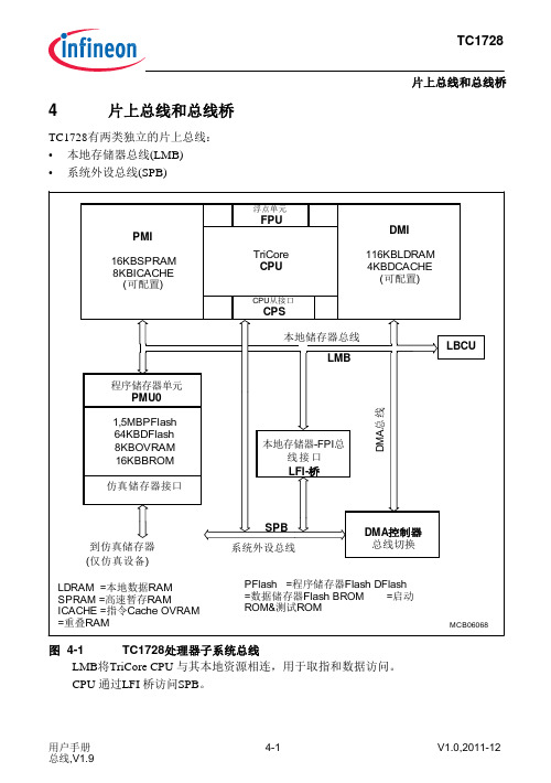
请求/授权
地址周期
数据周 期
MCA06109
图 4-2 基 本 L M B 传 送
传送1由三个周期组成,任何LMB传送均由这三个周期组成:
1. 请求/授权周期:LMB主设备准备执行读或写传送、请求LMB。若LMB可用,在 同一个周期内LMB主设备获得LMB控制器授权。
2. 地址周期:在请求/授权周期之后,主设备将地址送至LMB,所有LMB从设备 检查是否自身被寻址。
图4-4
LMB 总线控制单元寄存器
注: 表4-4地址栏中“偏移地址”是word(32-位)型地址。
中断寄存器 L BCU _SR C
LBCU_reg_its
表4-3
LBCU –寄存器地址空间
模块
起始地址
结束地址
注
LBCU
F87F FE00H
F87F FEFFH
表4-4 缩略名
LBCU_ID
LBCU 模块控制寄存器概览
用户手册 总线,V1.9
4-7
V1.0,2011-12
TC1728
片上总线和总线桥 4.3.4 LMB总线控制单元寄存器
图4-4和表4-4说明了LMB总线控制单元寄存器(LBCU)模块的所有地址映射。
LBCU单元寄存器概览
ID寄存器 LBCU_ID
控制寄存器 LBCU_LEATT
地址/数据寄存 器
表4-2
主设备优先级
优先级
LMB主设备
注
最高
DMA,高优先级
来自模块的DMA请求: -Cerberus高优先级1) -DMA 通道高优先级2)
LFI桥
DMA,中等优先级 数据存储器接口(DMI)
来自模块的DMA请求: -DMA 通道中优先级2)
英飞凌单片机例程tc1767_taskingv33r2_pll

Page 15
Exercise GPTA_PLL DAvE Configurations (cont.)
GPTA0 Clock Generation / FPC0:
Input line : GPTA0_IN0. CMP value :0x0010 Operation mode : no filtering on rising edge,immediate filter on falling edge.
Select Si Output High/Low Coherent_Update_Enable_Flag Toggle Si Line Output
Coherent update of the Period and of the Duty Cycle
confidenห้องสมุดไป่ตู้ial
Page 5
Exercise GPTA_PLL Objective
GPTA Clock Module clock:
Enable GPTA Module Select fractional divider mode Set the required module clock to 40MHz
confidential
Page 12
英飞凌tricoretc297用户手册中文版
英飞凌tricore TC297 用户手册中文版简介1.简介本用户手册描述了TC1728,一种基于英飞凌TriCore架构的新型32位微控制器DSP。
该文档涵盖了不同封装的TC1728和TC1724的特性。
关于本手册本用户手册的主要读者定位为设计工程师和软件工程师。
手册对TC1728的功能单元、相关寄存器、相关指令及异常情况处理进行了详细描述。
TC1728微控制器用户手册所描述的TC1728特性和TriCore架构紧密相关。
若TC1728直接实现了TriCore架构功能,手册中将其简称为TC1728特性。
手册在描述TC1728特性时若不提及TriCore架构,即表明TC1728直接实现了TriCore架构功能;若TC1728实现的特性是TriCore架构特性的子集,手册会在说明TC1728具体实现的同时指出它与TriCore架构的差别。
这些差别会在相关章节中予以说明。
相关文档TriCore架构的详尽描述可参见文档“TriCore架构手册”。
由于TriCore具有可配置性,不同版本的架构包括的系统组成可能因此不同,因此有必要对TC1728架构进行单独说明。
本用户手册和“TriCore架构手册”一起有助于用户完全理解TC1728微控制器的功能。
命名规则本手册使用下面的规则来命名TC1728的组成单元:TC1728的功能单元用大写表示。
例如:“SSC支持全双工和半双工同步通信”。
低电平有效的引脚,符号上方加横杠表示。
例如:“,具有双重功能”。
寄存器中的位域和位通常表示为“模块_寄存器名称・位域”或“模块_寄存器名称・位”。
例如大多数寄存器名包括模块名前缀,用下划线“_”和真正的寄存器名分开(例如“ASCO_CON”中“ASCO”是模块名前缀,“CON”是内核寄存器名)。
在描述外设模块的内核时,通常引用内核寄存器名;在描述外设模块的实现时,通常引用外带有模块前缀的寄存器名。
用户手册简介,简介…变量出现在大小写混用中,用来表示一组处理单元或寄存器。
英飞凌16位单片机2287-DAVE演示文档-CAN
CAN_2
Init Main • fsys=80MHz • Init USIC
Init MultiCAN • Module • Node 0 • Node 1 • Message Objects • Start nodes
Page 15
HOT Exercise CAN_1 - DAvE Configurations A MultiCAN settings
Configure CAN Node 1 Baud Rate: ¬ Required baud rate : 500 Kbaud ¬ TSeg2 : 5 to get Real baud rate at 500 Kbaud
Configure the XC2000 with DAvE Configure USIC 0 Channel 0 as a UART Receive a character from a PC and generate a receive interrupt Transmit the character on CAN node 0 and receive the CAN message on CAN node 1 Transmit the value back to the PC and toggle one of the LEDs on the board on receipt of every character
Configure CAN Node 1 General:
¬ Select P2.4 for Receive Input and P2.2 for Transmit Output
- 1、下载文档前请自行甄别文档内容的完整性,平台不提供额外的编辑、内容补充、找答案等附加服务。
- 2、"仅部分预览"的文档,不可在线预览部分如存在完整性等问题,可反馈申请退款(可完整预览的文档不适用该条件!)。
- 3、如文档侵犯您的权益,请联系客服反馈,我们会尽快为您处理(人工客服工作时间:9:00-18:30)。
Page 11
Exercise MEM_1 – Tasking Viper Reflash Project
Refresh files in the project Right click on „MEM_1‟ in the navigator
Select „Refresh‟ from the pull down menu
confidential
Page 5
Exercise MEM_1 Dave Configuration(cont.)
Save (File Save) this DAvE file in : d:\hot\tc1767\MEM_1\MEM_1.dav Let DAvE now generate the code for you Go to File Generate Code or click: DAvE opens a new window with the Project Documentation file. On the left hand side a browser window shows the generated files. You can take a look at the generated code or just find out in which file DAvE put the included functions. In general:
Programming the internal flash Exercise MEM_1
Exercise MEM_1 Objective
Objective: Pregram the internal Flash Run the code from here: on board LED will blink.
confidential
Page 4
Exercise MEM_1 Dave Configuration(cont.)
Project Settings - opens automatiБайду номын сангаасally General:
Fvco : 640MHz System Clock:80MHz
External oscillator
confidential
Page 19
Exercise MEM_1 Tasking Viper : Complete generated code
At the end:
// USER CODE BEGIN (Main_General,10) v o id del a y ( v o i d ) { v olatile int i , j ,k ; f or (i=0;i<50 0 0 ; i+ + ) for (j=0;j<2 0 0 ; j ++ ) k = i+ j ; } // USER CODE END
Interrupt table start address: 0xa00f 0000
confidential
Page 17
Exercise MEM_1 Tasking Viper : Complete generated code
On the following slides please find the code you have to add to the generated code. For reasons of orientation you will always find a few lines of already existing code as well. The code you really have to add looks like this:
confidential
Page 3
Exercise MEM_1 Dave Configuration(cont.)
Project Settings - open automatically General:
Compiler Settings: Tasking Use Infineon DAvE sfr Header.
Let’s get started now!
confidential
Page 2
Exercise MEM_1 Dave Configuration
Start DAvE for TC1767.
Create a new project: Go to File New Select microcontroller: „TC1767‟.
while( 1 );
Note: DAvE doesn‟t change code that is inserted in the „USER CODE‟ sections if you let DAvE regenerate code. Therefore, whenever adding code to the generated code, write it into a „USER CODE‟ section. If you want to change DAvE generated code or add code outside these „USER CODE‟ sections you have to modify your changes after each time you let DAvE regenerate code!
ldarm : 0xd000 0000.
pram : 0xf005 0000. pcode : 0xf006 0000.
confidential
Page 16
Exercise MEM_1 Tasking Viper : Setting Link script file(cont.)
Select and check Special area Reset start Address Trap table start address CSA start address Number of context block : 0xa000 0000 : 0xa00f 2000 : 0xd000 0000 : 64.
confidential
Page 18
Exercise MEM_1 Tasking Viper : Complete generated code(cont.)
Edit „main.c‟ - function „main‟ (almost at the end)
// USE R CO D E B EGI N (M a in, 9) voi d d el ay ( voi d); // Def in e P ort 5/ Pi n0 as gen er al IO P5_ IOC R0 = 0x 00 0 000 80; // end le ss loo p whi le( 1) { // set l ed off P5_ OUT = 0 x 000 000 01 ; // wai t del ay( ); // set l ed on P5_ OUT = 0 x 000 000 00 ; // wai t del ay( ); } // USE R CO D E E ND
confidential
Page 7
Exercise MEM_1 Tasking Viper : Create New Project
Click on Workbench (if not already there…)
1
confidential
Page 8
Exercise MEM_1 Tasking Viper : Create New Project(cont.)
if the included function is a macro it is included in the „.h‟ file if the included function is a function it is included in the „.c‟ file
file main.c and main.h will be generated
confidential
Page 13
Exercise MEM_1 Tasking Viper : Deselect the „sfr‟ file in Tasking
Set Project Properties Click on „Project‟ and „Properties‟ Click „Setting‟ and „Preprocessing‟ Disable „Automatic inclusion of „.sfr‟ file‟
Create New Project Click on File New Select „Tasking VX-toolset for Tricore C/C++ Project‟
1
confidential
Page 9
Exercise MEM_1 – Tasking Viper Create New Project(cont.)
confidential
Page 6
Exercise MEM_1 Tasking Viper : Select a workspace
Start TASKING VX-toolset for tricore Click on Open Project Work Space Filename: browse to “d:\hot\tc1767” Click „OK‟
Tricore Project Settings Click “AUDO Future Family” and select “TC1767” Enable “C startup code”,”Linker script file” and “synchronizaqtion file”
