活塞式压力计DH580使用说明
活塞式压力计标准装置操作规程
活塞式压力计标准装置操作规程一、使用前的准备1、压力计应放在平稳的检定工作台上,利用水平调整螺钉来校准水平,必须使气泡水平仪的气泡位于中间位置。
2、使用前,首先用汽油清洗压力计各部份,然后在手摇泵和测量系统内腔注满变压器油,并将内腔中的空气排除。
3、旋转手摇泵的手轮,检查油路是否畅通若有问题则应首先排除,直到油路畅通之后方可装上被检压力表(检氧压表应将油水隔离器装上)。
二、使用操作步骤1、打开油杯,左旋手轮,使手摇泵内腔充满油液。
2、关闭油杯阀,打开至活塞和被检表的切断阀,右旋手轮,产生初压,使底盘升起直到与指示面板刻废线相齐为止。
3、增加砝码质量,使之产生所需检定点的压力、增加砝码时,应不断转动手轮以免底盘下降,与此同时使砝码以不小于30r/min的角速度顺时针转动,以克服摩擦力矩影响。
4、当回检时,应先降压至接近被检分度线,在卸下砝码。
5、检验完毕后,打开油杯阀,卸去全都磁码,并将手轮右旋至顶端。
三、使用维护注意亭项1、使用砝码应轻放、以免损伤。
2、使用的变压器油,应该经过过滤,不许混入杂质或脏物,且使用一定时期后,须更换新油。
3、被检压力表的测量范围不得超过活塞式压力计的测量范围。
4、活塞、杆和活塞筒是精密器件,不准拆卸其他部分应分应分别定期清洗,清洗及安装时必须小心谨慎防止赃物混入。
5、活塞式压力计及其配套设备应定期送法定计量机构检定。
配热电阻用测温仪表标准装置操作规程一、使用前的准备工作按装置的工作原理,接好连接导线,并事先旋转几次标准电阻箱的各旋钮,使其接触稳定可靠。
二、使用操作无论是用于检定电子平衡电桥或动圈式仪表,只须旋转标准电阻箱上的上的旋钮,按旋钮上的指示数值再X倍率,其总和便是标准电阻箱输出的总和。
三、使用维护注意事项1、装置中的电阻箱只做检定仪表时使用,不能做其它测量使用。
2、使用中电阻箱的各旋钮不得旋转过快。
3、装置中的专用外线电阻必须按被检仪表的规定正确使用。
4、电阻箱应定期依法定计量机构检定。
一、二等活塞式压力计检定操作规程
一等标准活塞式压力计检定操作规程一:检定前准备工作1、启动空调,室温设臵为20℃,并根据实验室内实测相对湿度值,开启加湿器,控制室内相对湿度在45—75%之间。
2、被检一等标准活塞式压力计进行管路清洗、调装后灌充好工作介质,与DH型压力标准装臵正确连接,并臵于上述恒温下至少4个小时。
3、检查DH压力标准装臵各阀状态、传压介质油是否干净和充分,并将压力伺服器与伺服控制面板电源打开预热。
4、用标准水平仪进行被检压力计与标准压力计水平调整工作。
5、操作各阀与加压泵,进行导压管路排空作业。
6、准备好其它辅助设备(包括:一类一级、三级标准天平,二等工作砝码,千分表,秒表等)。
二:进行被检压力计的外观检查1、记录名称、器号、测量范围、准确度、制造厂家与出厂年月。
2、检查活塞压力计的承重盘、活塞筒应安装正确、配合良好,器号与专用砝码号一致。
3、用手拨转活塞,活塞应灵活旋转,不得有明显卡阻、频变现象。
其表面应光滑,无影响计量性能的锈点。
4、活塞、承重盘与专用砝码无砂眼和明显损伤。
三:进行承重盘平面对活塞轴线垂直度的检查1、将水平仪放于承重盘中心处,在不转动承重盘的情况下,将水平仪水平或转动90°摆放调整压力计水平调整螺钉,反复进行承重盘水平调整。
2、分别将水平仪放在0°或90°的位臵上,在每个位臵上将承重盘转动90°和180°,观察水平仪气泡位臵的偏移量不应超出计量检定规程对该指标的要求。
四:活塞转动延续时间的测量1、加压至被检压力计量程的50%,并使被检活塞处于工作平衡位臵。
2、以每10秒20转的初旋转速度顺时针转动活塞,并开始计时,至活塞完全停止时记录转动延续时间。
3、如此反复3次,其中须有两次的记录值满足检定规程对该项指标的要求。
五:活塞下降速度的测量1、加压至被检压力计的量程上限,并使被检活塞处于工作平衡位臵。
2、关闭活塞传压截至阀,并以每分钟60转的速度顺时针转动活塞承重盘与砝码。
活塞式压力计说明书JQ型
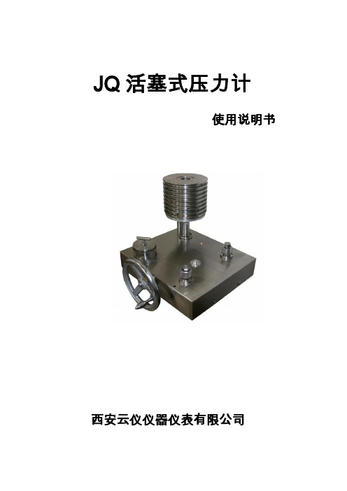
JQ活塞式压力计使用说明书西安云仪仪器仪表有限公司产品简介:JQ活塞式压力计是我公司第三代产品,此产品是在YS活塞式压力计和KY活塞式压力计的基础上取长补短研发而成,具有性价比高,皮实耐用,活塞系统有防断机构,大大减少了活塞杆因为操作不当而造成的损害,JQ活塞式压力计是真正为大批量计量而生产研发的最新代活塞式压力计。
性能特点:1、采用焊接式结构,不存在震动对气密性的影响,气密性非常好。
2、活塞杆采用特种碳化钨,不仅仅保证了活塞系统的硬度,还在最大程度上保证了活塞系统的韧性。
3、活塞式压力计采用保护杆结构,保护杆直径10.03毫米,保护筒直径10.06毫米,在活塞式压力计误操作和摇摆时,保护装置可以保护活塞杆不损坏,大大加强了活塞式压力计的实用性和便捷性。
(核心技术国内首创)4、活塞式压力计采用安装在活塞式压力计固定装置里,无需专用工具,方便客户安装,清洗。
5、活塞式压力计的位移系统采用变色指示灯指示,在活塞下限红灯亮,平衡位置时变指示灯颜色变为黄色,上限时为红色灯亮,一只变色指示灯即可实现这个功能(国内首创)。
6、活塞杆位移量从原来的3毫米改为现在的5毫米,活塞起降幅度更大,稳定时间更长,更适合批量生产计量实用。
7、台面采用不锈钢台面(0.02级),台面干净整洁,无额外的其他装置,方便后期维护。
8、活塞式压力计不再采用挂蓝结构而采用了地盘结构,单手放置砝码即可,更加方便。
9、JQ 活塞的一系列改进,都是为了实用性这一目标,在活塞系统的研发上,怎样好用还不容易坏,怎样放置砝码方便,希望这款活塞真正能让计量更便捷。
主要参数:测量范围和测量准确度:此活塞式压力计为油介质,本公司还有水介质活塞式压力计和气介质型 号 测 量 范 围(MPa)准 确 度JQ-0.6 0.04~0.6 ±0.05% ±0.02%±0.01%JQ-6 0.1~6 JQ-25 0.5~25 JQ-60 1~60 JQ-100 2~100活塞式压力计。
活塞式压力计操作规程

活塞压力计操作规程
一、使用前调整底座螺丝,使压力计处于水平位置,然后向油杯注入变压器或蓖麻油,油位最好达油杯深度的5/6。
二、将被检表与压力计校验接头接好,不得有渗漏,打开油杯进油阀,逆时针退回手轮,将油抽入活塞腔内,关闭进油阀。
三、根据被检仪表的刻度,在砝码盘上加相应的砝码,用手缓慢顺时针旋转手轮,直至砝码上升到刻度线,再用手轻轻转动砝码盘,转速约30转/分,此时被检表的指示值与砝码值之差即为被检表的误差。
每次加砝码后加压时,要用手轻轻转动托盘一次。
四、检定完毕后应先把油抽回,然后打开进油阀,关闭被检表阀门及砝码盘的阀门,取下砝码,当活塞上压力未降到零时,不准先取下砝码。
五、使用完毕一定要将手轮沿顺时针方向旋转到极限位置,砝码及托盘一定要擦干净,不得有任何东西附于上面。
六、压力计真空计在检定真空表时,应将砝码盘往下转180℃,使其处于水平位置,将真空泵上接头从空气输出接头换到抽真空接头上。
七、压力计真空计使用完毕应将剩余的空气(疏空)排掉,切断真空泵电源。
八、在仪器上装卸被检表时,不得一手狞住表,另一手板手轮(或丝杆)以免扭弯丝杆。
九、长期不使用时,在砝码及托盘上涂一层凡士林油防止绣蚀。
摘自:中国石油天然气第六建设公司机械设备安全技术操作规程Q/ZYLJ 05.01-2005。
活塞式压力计(碳化钨标准型)

新规程活塞压力计(碳化钨标准型)CW-600TCW-60T、CW-6T性能特点●活塞在起始量程测量延续时间,各项指标完全符合JJG59-2007 《活塞式压力计》、JJG99-2006 《砝码》、国家计量检定规程。
● 活塞和活塞筒经精工研磨,其圆度误差和间隙极小,因而极大的提高活塞转动延续时间,也就相应减小活塞下降速度,提高活塞鉴别力。
●两个被检表接头处设计有两个截止阀,截止阀能及时关闭被检系统之间的压力。
由于活塞式压力计在加减砝码时,必须减压将活塞降下来,而被检精密压力表、压力变送器、传感器等和系统之间若不能被截止,表中的压力会随着活塞升降而升降,则考核不出被检表的回程误差,特意设计的压力转换阀,在关闭时,可不用砝码单独工作,即活塞压力计套子可作为压力泵或压力源独立使用。
●活塞工作位置采用一体式双排液晶数字光标(国内首创)显示的位移传感器监测,具有灵敏、醒目、准确的优点。
●砝码已经进行压力形变系数和当地重力加速度的修正。
●可选配数字显示功能:温度、位移、时间、转速、压力等参数的数字显示;可选配电机,使活塞由电机带动旋转。
●测量范围:名义标称测量范围与实际测量范围一致●活塞系统可以方便拿出送检(不用携带沉重的主机台)●可作为传递用检定活塞式压力计;也可高精度测试用。
可配kg砝码和Mpa砝码●加压系统先进,轻便耐用!柔弱女子即可轻松打压至100MPa●砝码采用挂篮结构,重心低,稳定性极好。
●同时检定两只被检表,采用快速压力接头,绝无漏油现象●每台均出具中国计量科学研究院或中国测试技术研究院《检定证书》主要技术指标型号:CW-6T 、CW-60T 、CW-250T、CW-600T 、CW-800T 、CW-1000T 、CW-1600T标称范围/测量范围:0.04 ~0.6MPa ; 0.1~6 MPa ; 0.5~25 Mpa;1~60 Mpa ;1~80Mpa ; 2~100 MPa ;2~160 Mpa;5~250 Mpa准确度:0.005级(±0.005% );0.01级(±0.01%);0.02级(±0.02%);0.05级(±0.05% )功能:量传活塞压力计;检定压力计、压力表、压力变送器等。
活塞式压力计操作规程

活塞式压力计操作规程
《活塞式压力计操作规程》
一、前言
活塞式压力计是一种常用的压力测量仪器,广泛应用于各种工业领域。
正确操作活塞式压力计可以保证测量的准确性,提高工作效率,避免事故的发生。
因此,本规程制定了活塞式压力计的操作规程,以确保每位操作人员都能正确使用该压力计。
二、操作步骤
1.准备工作
(1)检查压力计的外观是否完好,有无损坏及严重腐蚀;(2)确认压力计的刻度盘是否清晰可见,刻度是否准确;(3)检查压力计的连接管路是否密封良好,无泄漏现象;(4)准备好所需的压力计标定器具。
2.测量操作
(1)将压力计连接至待测设备的压力管路上,注意连接处应保持干净,并确保连接牢固;
(2)打开被测设备的压力阀门,将压力传递至压力计内;(3)观察刻度盘,记录读数,并确保读数稳定后再进行下一步操作;
(4)关闭被测设备的压力阀门,释放压力,将压力计从测量管路上拆下。
3.记录和存储
(1)将测量所得数据及时记录在测量记录表中;
(2)将测量记录表存档,便于日后查阅和分析。
三、注意事项
1.在操作过程中,应注意安全,避免因操作不慎导致意外伤害发生;
2.操作前应认真检查压力计及其连接管路,确保完好无损;
3.在撤除压力计时应先关闭被测设备的压力阀门,避免剩余压力对操作人员造成伤害;
4.测量记录表的存档要求整齐,方便查阅。
通过对《活塞式压力计操作规程》的认真遵守和执行,可以保证每台活塞式压力计的正常运行和准确测量,为工程设计、设备维护和安全防护提供科学数据支持。
活塞式压力计
测量范围(MPa) 标称上限(MPa) 标称下限(MPa) 测量上限(MPa) 测量下限(MPa) 活塞公称面积(cm2) 公称质量(Kg) 产生的压力 (MPa) 公称质量(Kg) 专用 砝码 产生的压力 (MPa) 数量(块) 接口螺纹规格 重 量(Kg)
底 盘 及活塞
工作介质
25#变压器油与航空煤油的混 癸二酸二(2-乙基己基)酯,其 20℃时运 合油(比例 4.39:1),其 20℃时 2 动 粘 度 20 ~ 25mm /s , 酸 值 不 大 于 2 运动粘度 9~12 mm /s,酸值 0.05mgKOH/g。 不大于 0.05mgKOH/g。
一、产品外观及型号
0.6MPa 型
6MPa 型
-1-
25MPa/60MPa 型
二、结构示意图
0.6MPa 型
三、用
途
可用于量值传递和高精度测量。
四、工作原理与基本结构
活塞式压力计(以下简称压力计)的工作原理是基于作用在活塞下端 面流体压力所形成的力与施加于活塞上端砝码所产生的重力相平衡的原理 制成。 本压力计有下列特点:它的活塞系统(活塞、活塞缸)用碳化钨制造, 形变和温度附加误差小、耐磨,可以能长期保持活塞系统尺寸不变;测量 范围在 25MPa(包括 25MPa)以上的压力计用癸二酸二(2-乙基己基)酯作 为传压介质,其粘度在 20℃时为(20~25)mm /s,远小于国内一般压力计 -32
图七 e.第一点读数后,应用调压器降压;使活塞下降至最低位置,然后在 压力计上加放与第二点测量相应的砝码值,再用调压器加压并读数,直至 正行程测量完毕。 f.反行程测量时,仍需用调压器降压。操作中避免用油杯阀降压,特 -10-
别在高压测量时,此操作法很可能震断活塞从而损坏压力计。 g.测量完毕,应打开油杯阀,将调压器丝杠旋入,恢复原状,取下被 测量仪器。
高压活塞式空压机操作流程及注意事项
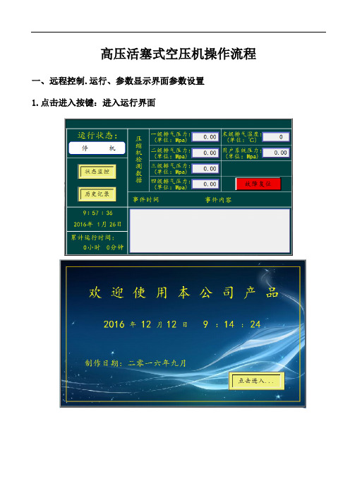
高压活塞式空压机操作流程一、远程控制.运行、参数显示界面参数设置1.点击进入按键:进入运行界面1.1运行状态:显示当前压缩机的运行状态。
1.2累计运行时间:压缩机使用时间。
1.3压缩机实时数据:显示当前压缩机的压力,温度等数据。
1.4各机构的运行状态:显示辅机的运行停止、主机的运行停止状况。
2.报警、报警停机参数界面2.1设置当前压缩机的压力、温度预警参数2.2设置当前压缩机的压力、温度报警停机参数2.3参数设置,如要修改各项参数值,请先点击密码输入区:,点击密码数值框,然后弹出桌面2.4数字键盘:,密码输入完毕后,点击键。
然后点击所需要修改的项目,入:(一级排气压力高)点击参数值框,然后弹出桌面数字键盘,输入修改值,输入完毕后,点击键,参数即可修改成功。
注: 进入参数修改需要管理员权限,如下图所示3.控制柜、操作面板显示与说明控制柜外形尺寸为:1700×600×500,电气控制柜采用双层门,带有防雨帽,具有防雨、防风、防腐、防锈等功能。
下图为控制柜外形图形,以及面板操作界面。
(定制控制系统柜)3.1启动按钮:按下启动按钮,(辅机指示灯亮)(停机指示灯灭),冷却风机运行,延时5秒后,主机启动,(主机指示灯亮)主机运行。
3.2停机按钮:按下停机按钮,主机停止运行,各级放污阀延时打开,辅机延时10秒后,停止运行,压缩机停机(停机指示灯亮),3.4急停按钮:在压缩机遇到紧急情况时,按下急停按钮,压缩机控制柜将断开总电源,控制柜断电,压缩机停止运行。
3.5触摸屏复位按点击复位键,故障报警复位,报警消除。
3.6工作指示灯:各指示灯显示当前压缩机的运行情况。
3.7电压表:显示当前电压状况。
3.8电流表:显示当前电流状况。
二、高压活塞式空压机机组的使用与维护本章主要介绍压缩机的使用与维护,有关柴油机的使用与维护,请严格按照其说明书进行。
2.1使用2.1.1 准备⑴检查各连接部位的紧固性及传动皮带的松紧度。
活塞压力计操作规程

活塞式压力计操作规程1、压力计应放在便于操作和坚固的无震的平台上。
2、操作前首先利用水平调节螺丝来校准水平,即须使水平泡的气泡位于中心位置。
3、压力计的工作环境温度为20±10℃,相对湿度80%以下,周围空气不得含有腐蚀气体。
当温度超过20±5℃时应用下式进行温度校正;△P2=P(a1+a2)(20-t)(MPa)式中:P-测量的压力值(MPa)a1,a2-活塞和活塞缸材料的线膨胀系数。
a1=11.7×10⁻⁶ /℃a2=17.6×10-6 /℃t-环境温度4、初使用时,首先用汽油清洗压力计各部分,然后在手摇压力泵和测量系统的内腔注满传压介质,并将内腔中的空气排除。
传压介质的油液必须经过过滤,不许混有杂质和污物。
5、压力计中的活塞杆和活塞缸均是精密零件,平时不得轻易拆卸。
其他各部件则应定期清洗和调换传压介质的油液。
清洗和安装时都必须谨慎小心,防止污物和擦布纤维混入。
6、旋转手摇泵的手轮,检查油路是否通畅;若无问题,则即可装上被检查压力表。
其操作步骤:(1)打开油杯阀门,左旋手轮,使手摇压力泵的油缸充满油液。
(2)关闭油杯阀门,打开针形阀,右旋手轮,产生初压,使承重底盘升起,直到与定位指示筒的墨线刻度相齐为止。
(3)增加砝码重量,使之产生所需的检验压力。
增加砝码时,需相应转动压力泵手轮,以免承重底盘下降。
操作时,必须使底盘按顺时针方向旋转,角速度保持在30~120转/分之间。
借以克服摩擦阻力的影响。
(4)检验完毕,左旋手轮,逐步卸去砝码,最后打开油杯阀门,卸去全部砝码。
7、在关闭压力计上的阀门时,务必顺势关闭之(以无泄露现象为准),切勿用力过甚。
580操作说明
全自动双链式锁眼机 全自动单链式锁眼机
操作说明 安装说明 服务说明
Postfach 17 03 51, D-33703 Bielefeld. Potsdamer Straße 190, D-33719 Bielefeld
Telefon +49 (0) 521 / 9 25-00 • Telefax +49 (0) 521 / 9 25 24 35 •
2. 在投入使用之前,也要阅读马达供应商的安全条例及用法说明。
3. 该机器必须用于指定的用途。不允许在没有安全装置的情况下使用机器。 请遵守所有相关安全规定。
4. 当进行更换针距(机针,压脚,针板,送布板及弯针),穿线,操作人员离开 及维护时,必须切断机器总开关或拔除电源插头。
5. 日常维护工作必须由受过适当培训的人员进行。
保留所有权利。 Dürkopp Adler AG 公司财产及版权。如没有经过 Dürkopp Adler AG 公司书面允许,不得以任何方式复制,转载及出版本手册 内容
版权所有 © Dürkopp Adler AG 公司- 2008
序言
本说明书有助于用户熟悉机器,并依照建议更好地使用机器。
本说明书包含如何安全,正确及经济地操作机器的重要信息。阅览本说明书可 消除危险性,减少维修和停机时间成本,提高了机器的可靠性和使用寿命。
本说明书旨在补充现有的国家事故预防及保护环境的法规。
本说明书必须始终放在机器/缝纫装置附近,以备使用。
经授权将使用机器/缝纫装置的人员,必须认真阅读本说明书,并严格按照本说 明使用机器/缝纫装置。这意味着:
– 操作,包括装配,在工作周期故障排除,移除费料 – 服务(维护,检查,维修)和/或 – 运输
活塞式压力计
一等宽量程活塞式压力计概述TY 系列宽量程活塞式压力计是我研究所按照国家最新“活塞式压力计”检定规程要求新研发设计制造。
由于活塞式压力计的关键部件使用了高硬度和低温度线膨胀系数的碳化钨材料, 从而提高了活塞的耐磨性 ,因此受压力后形变极小(可忽略不计),性能极其稳定。
活塞的工作介质采用了癸二酸二异辛酯,从而使压力计具有极高的灵敏度。
由于采用了新材料、新技术、新工艺,所以新的活塞式压力计的各项技术指标有了很大提高。
从而广泛用来检定数字压力计、精密压力表、压力变送器、压力传感器等压力仪器仪表。
性能特点:1. 活塞和活塞缸均采用高强度、高硬度、和低温度线胀系数的硬质合金碳化钨材料经过精心研磨制成,工作环境温度宽,性能稳定 20±5℃。
2. 负荷重心低,砝码通过挂篮直接加在活塞上,活塞运转平稳,压力波动极小,示值准确。
3. 25MPa 以上传压介质采用粘度很小的癸二酸二异辛酯,从而保证压力计有极高的灵敏度。
4. 压力计所用砝码全部采用无磁不锈钢或碳钢材料制做。
5. 活塞工作位置用位移传感器监测,活塞工作行程为3mm(指针型、数字型可选)。
6. 加压调节轻便省力,即使在100MPa 压力时也能轻松自如。
7. 压力输出两幅快速接头(M20×1.5的内螺纹),可同时校验两个仪表。
主要技术参数:1. 测量范围和测量准确度等级在环境温度(20±2) ℃,温度波动不大于0.5℃条件下其测量准确度等级见表一 型号测量范围(MPa ) 准确度 TY-0.60.04-0.6 0.01% 0.02% 0.05%TY-60.1-6 TY-250.5-25 TY-601-60 TY-100 1-100 2. 砝码的质量和数量见表二使用提示:1.活塞安装方法可在本网站观看“活塞压力计安装教程视频”教材。
2.活塞工作位置显示表有两种,分为指针型和数字型;活塞的工作行程都是3mm.指针型表的刻度为±1.5mm,无压力时为-1.5mm, -1.5mm 到+1.5mm 都是正常工作范围,建议工作在0 - 0.5mm处(中间偏上)。
活塞式压力计操作指导

活塞式压力计操作指导一、正确使用活塞式压力计(1)对新购置的活塞压力计要用高标汽油对活塞系统、压力泵、油杯、管路进行反复清洗。
清洗完毕.待汽油全部挥发后,注入清洁的工作介质(变压器油或药用蓖麻油)。
(2)活塞压力计应安置在便于操作,牢固无振动的工作台上,台面用坚固且富有弹性的材料制成。
除放置压力计和砝码外,台面上还应留有适当的空间方便记录和放置必要的工具。
(3)活塞压力计须用水准器进行调整,使承重盘平面处于水平位置,同时保证活塞杆的垂直度。
(4)活塞压力计使用时应缓慢升压和降压,如急速加,减压力.不仅会冲击活塞,面且会有危险。
特别是在活塞有负荷的情况下,用打开帅杯阀门进行减压,则更具危险,这种操作应当禁止。
(5)活塞上加、减砝码时,应轻拿轻放,上下砝码应人槽中。
若砝码偏心,不仅会引起测量误差,而且会加速活塞系统的磨损。
(6)使用活塞压力计时,应接顺时针方向以30~60r/mirl初速度转动砝码,并使承重盘底面对准限止器基面。
(7)压力计使用时环境温度要求:O. 05级、0.2级活塞压力计,使用温度为(20±5)℃。
(8)活塞压力计的检定周期最长为2年。
(9)活塞压力计不使用时,应用防尘罩罩好,以防止灰尘和异物落在仪器上。
二、活塞式压力计的日常维护1.应经常保持压力计清洁,压力计不放在湿度过大的环境中,以免锈蚀。
2.快速接头和活塞缸下端O形圈较易损坏,、若发现泄漏应予以更换。
3.油杯中液面应经常高于油杯过滤器罩子上端面,若一时疏忽,空气将进入预压泵中,造成预压泵失效。
这时应拧松预压泵进油接头,使空气随液体流出而流。
三、工作介质25MPa 以下为变压器油或变压器油与煤油的混合油20 ℃时运动粘度9 ~12 厘池酸值不大于0.05 毫克KOH/ 克。
25MPa 以上(含25MPa )为癸二酸酯(癸二酸二异戊酯或癸二酸二异辛酯)20 时运动粘度20 ~ 25 厘池,酸值不大于0.05 毫克KOH/ 克。
怎样使用活塞式压力计

怎样使用活塞式压力计简介活塞式压力计是一种广泛使用的压力测量仪器,特别是在工业领域中。
它可以测量气体或液体在管道、容器或其他封闭系统中的压力。
本文将介绍活塞式压力计的基本使用方法和注意事项。
步骤准备工作在使用活塞式压力计之前,需要完成以下准备工作:1.选择正确的活塞式压力计。
确保选择的压力计可以满足你的需求。
不同的压力计可以测量不同范围的压力,因此需要根据需要选择合适的型号。
2.检查压力计的完整性。
确保每个配件都齐全,例如压力表、指针和连接设备等。
3.检查活塞式压力计是否清洁。
清洁压力计的内部和外部表面,确保没有灰尘、油渍或其他污垢。
连接压力计1.确定测量点。
在需要测量压力的管道、容器或其他封闭系统中,找到合适的位置进行测量。
确保测量点没有泄漏或其他问题。
2.连接压力计。
将压力计的连接设备与测量点相连接。
确保连接设备的密封性良好,以防止压力泄漏。
3.调整阀门。
通过调整连接设备上的阀门,调整内部压力,确保压力计可以正确地测量压力。
测量压力1.打开读数器。
在使用活塞式压力计之前,需要打开读数器,以记录测量数据。
2.向压力计施加压力。
通过调整连接设备的阀门,输入压力到压力计中。
在输入压力时,需要逐渐增加压力,以防止压力数值突然增加,导致设备损坏。
3.读取压力值。
当压力稳定时,读数器上的数值即为测量压力。
将压力数值记录在记录表中,作为后续处理的依据。
完成测量1.关闭阀门。
在完成测量之后,需要关闭连接设备上的阀门,以防止压力泄漏。
2.关闭读数器。
在记录数据之后,可以关闭读数器,并将记录的数据输入电脑或其他处理设备中进行分析或图形化表示。
注意事项使用活塞式压力计时,需要注意以下事项:1.确保正确连接压力计,以防止压力泄漏或误差。
2.不要过度施加压力。
过度施加压力可能损坏设备。
3.避免在高温或高湿度环境下使用压力计。
4.定期校准压力计,以保证其精确度和可靠性。
5.储存压力计时,需要将其放置在干燥、通风和不含腐蚀性物质的地方。
测压器使用方法

测压器使用方法
测压器的使用方法如下:
1. 将连接软管与血压计的充气管接头连接好。
2. 连接电源适配器,打开充气管的阀门为软管充满气,将充气管紧固
在血压计上。
3. 将充气管打开使气流畅通,指针摆动到零位。
4. 摆好位置面对压力表,若充气管外表面有红色标记,证明血压计已
与压力表三通相通。
5. 打开充气管开关,进行测压,观察压力表上数值。
关闭充气管开关,余压保存。
6. 充气管长时间使用或保管不当可能漏气,当指针摆动时感觉不到空
气流动时,请及时更换气囊。
如果上述步骤不能解决问题,请查看厂家使用说明书或咨询专业人员。
测压器是一种用于测量一定封闭腔体内压力的装置,常见于科研、生产、检修等场合。
活塞式压力计使用方法【干货技巧】
以下为活塞式压力计使用方法,一起来看看吧。
1、活塞压力计应安装在便于操作、牢固无振动的工作台上,台面用坚固而富有弹性的材料制成。
2、新购置的活塞式压力计要用高标汽油对活塞系统、压力泵、油杯、管路进行反复清洗。
待汽油全部挥发后,向校验器注入清洁的工作介质,并用手轮打压,反复几次,直到校验器与活塞连接口处无气泡渗出后,将活塞筒安装在校验器上,用手轮加压至活塞筒内充满介质,再把活塞杆表面涂上工作介质后插入活塞筒内,以确保活塞系统内没有空气存在。
3、压力计工作介质的选用非常重要。
应选择在量程范围内有效的流动性,压缩率小及没有腐蚀的工作介质。
一般可以选用变压器油、变压器油和煤油的混合液及药用蓖麻油。
使用前一定要对其介质的运动黏度及pH值进行测定,符合要求后方可使用。
具体要求见检定规程。
4、活塞式压力计在工作前一定要调好水平。
一具体做法是:用手轮打压,使活塞升到工作位置,将条形水准仪放在承重杆托盘的平面上,转动活塞分别在水平面0°、45°、90°及135°处反复调整至符合要求。
这实际上要求承重底盘平面与活塞中心线保持垂直,使砝码重力垂直作用在活塞有效面积上,二、三等级活塞式压力计的不垂直度不得超过5°。
5、活塞式压力计的工作位置不带限止器的活塞式压力计,活塞浸入活塞筒的位置,应为活塞全长的2/4~3/4;带有限止器的活塞不得触及限止器;带滑动轴承和带滚珠轴承的压力计,将活塞升至工作位置的指示线为活塞式压力计的工作位置。
6、当活塞升压至所需要的压力值时,活塞在工作位置上须按顺时针方向,以30~60r/min的初角速度旋转,并能保持在工作位置。
7、活塞式压力计的专用砝码要保持清洁。
使用时轻拿轻放。
加放砝码时,一定要保证砝码与砝码之间配合紧密。
否则,压力计工作时转动活塞容易将砝码甩出,误伤操作人员或损坏仪器设备。
8、活塞式压力计与专用砝码一定要按要求配套使用,因为压力计的活塞有效面积不同,与之配套专用砝码的质量也不同。
先导活塞式减压阀说明书
先导活塞式减压阀说明书
L安装
1.1选择安装位置:选择一个离液体或气体供应源较近的位置,确保减压阀可以方便地连接到管道系统。
1.2连接管道:使用合适的管道和接头将减压阀连接到系统中。
1.3注意方向:确保减压阀的箭头指示流动方向,正确安装以确保正常工作。
2.调节压力
2.1了解工作压力:在安装前,了解你系统所需的工作压力范围。
2.2调节旋钮:根据需要,使用减压阀上的旋钮进行调节,以将系统压力维持在所需范围内。
2.3小心操作:调节压力时,小心进行,以避免过度调节或损坏减压阀。
3.定期检查和维护
3.1检查泄漏:定期检查减压阀及其周围是否有泄漏。
3.2清理阀体:确保减压阀的阀体清洁,防止灰尘或杂物影响正常运作。
3.3定期维护:根据制造商的建议,定期进行维护,如更换密封件、润滑部件等。
4.安全使用
4.1符合规范:确保减压阀符合相关的安全和规范要求。
4.2不要超负荷使用:避免超过减压阀的额定工作压力范围。
4.3避免物理损害:避免碰撞、挤压或其他物理损害。
活塞式压力计操作规程作业指导书
活塞式压力计操作规程作业指导书一、使用前检查(1)、基本技术指标测量压力范围:0.04-60Mpa精度等级:二等(0.05级)使用介质:变压器油工作环境温度:20±5℃,周围空气不得含有腐蚀性气体。
最大允许误差:压力值在测量范围下限以下时为测量范围下限的±0.05%;压力值在测量范围内时,为实际测量压力值的±0.05%。
(2)、使用前检查1、压力计表面有无损伤;2、油杯中是否有足量的仪表油;3、仪器是否在水平位置,如不在,调整螺钉校准水平。
二、操作步聚1、打开所有阀门,将手摇泵和测量系统的内腔注满仪表油,检查油路是否畅通,将内腔中的空气排出;2、装砝码及被校压力表;3、打开油杯阀,左旋手轮,使手压泵油缸充满仪表油;4、关闭油杯阀,打开使用阀;5、右旋手轮,产生初压,使底盘升起到与指示板的上端相齐为止;6、增加砝码重量,使之产生所需之校验压力,记录上行压力值;(增加砝码时,应不断转动手轮,以免底盘下降,操作时,必须使底盘及砝码以不小于30转/分的速度顺时针方向旋转);7、如果右旋手轮全部进入油缸,压力还低时,则关上相应阀重复3.4.5.6;8、上行校验完毕,左旋手轮,逐步卸去砝码,记录下行压力值;9、如左旋手轮全部旋出后,压力值还高,则可右旋手轮到一定压力值,然后慢慢打开油杯阀降压到一定压力值,再左旋手轮,到下行校验压力,记录下行校验压力值;10、校验完毕后,打开油杯阀,卸去全部砝码,拆下被校压力表,将手轮旋回。
三、使用后的安全管理(1)工作完工后:整理仪器、工具、现场,做好卫生。
(2)维护保养:1、压力计除活塞杆和活塞筒是精密零件,不得轻易拆卸外,其他各部分应定期清洗,清洗及安装时都必须谨慎小心,防止脏物或擦布纤维混入;2、油液必须过滤,不许混有杂质或脏物,经使用一定时间后,必须更换新油;3、不用时必须盖上防尘罩,以免尘埃进入压力计内;4、每使用一年,必须送计量机关重新检定。
- 1、下载文档前请自行甄别文档内容的完整性,平台不提供额外的编辑、内容补充、找答案等附加服务。
- 2、"仅部分预览"的文档,不可在线预览部分如存在完整性等问题,可反馈申请退款(可完整预览的文档不适用该条件!)。
- 3、如文档侵犯您的权益,请联系客服反馈,我们会尽快为您处理(人工客服工作时间:9:00-18:30)。
DH ■Budenberg 580 SeriesHydraulic Dead-Weight TestersOperating and Maintenance InstructionsDH ■BudenbergPO Box 224, Altrincham, Cheshire WA14 4FYTel: 44 - (0)161 - 942 - 4700 Fax: 44 - (0)161 - 942 - 4701E-mail: sales@Copyright © DH ■Budenberg limited, 1999.No part of this document may be reproduced, or translated, in any form, electronicor otherwise without the prior written consent of DH ■Budenberg.Neither DH ■Budenberg nor its Agents will be liable for incidental or consequential damagein connection with the use of this document.DH ■Budenberg reserve the right to change the contents or form of this manual at any timewithout prior notice having been given.This product must only be used for the express purposes as advertised by DH ■Budenbergand as referred to in this and other DH ■Budenberg approved literature.AUGUST 1999CONTENTSPage1 SECTION TITLE PAGE SAFETY PRECAUTIONS2Mineral oils health and safety (C.O.S.H.H.) information2Lifting of weights21DATA SHEET3 1.1Tester dimensions3 1.2Pressure ranges3 1.3Liquids used32DESCRIPTION5 2.1General5 2.2580 series base unit6 2.3580L piston unit8 2.4580M piston unit8 2.5580DX piston unit8 2.6580HX piston unit8 2.7580VHX piston unit8 2.8Functional103INSTALLATION11 3.1Unpacking the tester11 3.2Environmental requirements11 3.3Assembly of base units11 3.4Packing list124OPERATING INSTRUCTIONS16 4.1Procedure16 4.2Completion18 4.3Pressure calculation computer software standard accuracy program18 4.4Cleaning gauges19 4.5T emperature measurement of piston units195FAULT FINDING216PERIODIC MAINTENANCE23 6.1Cleaning the unit and checking the liquid levels237CORRECTIVE MAINTENANCE24 7.1General24 7.2Removing cover24 7.3Reservoir seals24 7.4Valve seals24 7.5Screw pump26 7.6Hub assembly26 7.7Piston/cylinder unit27 7.8Factory overhaul and re-certification of dead-weight testers278SPARE PARTS29 8.1Spare parts list30 8.2Spare seal identification chart30 8.3Ordering spares329OPTIONAL EXTRAS33 9.1Model 29 power rotation unit33 9.2Oil free testing33 9.3Fine increment weights33 9.4Model 27 - two gauge stand33 9.5Model 360 base33 9.6Model 433 and 436 carrying cases33 9.7Model 437 storage cases33 9.8UKAS Certification33ContentsSAFETY PRECAUTIONSAUGUST 1999 Page2Safety PrecautionsMINERAL OILS HEALTH AND SAFETY (C.O.S.H.H.) INFORMATIONDH■Budenberg provide hydraulic mineral oil in 500 ml containers labelled “ISO VG 22” for use up to 1400 bar in dead-weight testers and pressure comparators. It is no more hazardous than other common lubricating oils.It is the nature of the way in which this equipment is used, that there could be frequent and/or prolonged skin contact;in a few individuals this could give rise to skin irritation (Keratosis or Dermatitis). The use of an effective barrier creamwill greatly reduce this possibility.DESCRIPTIONClosed flash point:greater than 120°C.Storage:not above 30°C.Oral LD 50:15 g per kg body weight.Threshold limit value: 5 mg/m3.Fire extinguishing media:carbon dioxide/dry chemical foam or water fog.Spillage:soak with absorbent clay or proprietary absorbent.Waste disposal:burn or dump in approved area.EMERGENCY TREATMENT OF ACUTE EFFECTSIngestion:Do not induce vomiting.Administer 250 ml milk or olive oil.The main hazard following accidental ingestion is aspiration of liquid into lungs.Aspiration:Send to hospital immediately.Inhalation:Remove to fresh air, if nausea persists seek medical attention.Eye Contact:Wash with copious amounts of water for at least 10 minutes. If irritation resultsor persists, obtain medical advice.Skin Contact:Where skin rashes or other abnormalities occur as a result of prolonged orrepeated contact, medical advice should be obtained as soon as possible.OTHER LIQUIDSFor some very particular applications we supply specially constructed liquids. Copies of manufacturer’s data will be sent to users on request.LIFTING OF WEIGHTSCare must be taken when lifting the weights for the dead-weight tester. Each weight must be lifted individually and never attempt to lift stacks of weights on or off the tester.AUGUST 1999SECTION 1 - DATA SHEETSPage3Data Sheet1.1TESTER DlMENSIONSWidth=400 mmDepth=400 mmHeight (with 580 M piston unit)=205 mmHeight (with 580 L piston unit)=220 mmHeight (with 580 DX, HX or VHX piston unit)=280 mmMass - without weights=17,2 kg (inclusive of piston unit and oil fill)1.2PRESSURE RANGES580 base with 580 L piston unit 1 to 120 bar (10 to 1,600 Ib/in2)580 base with 580 M piston unit 2 to 300 bar (30 to 4,000 Ib/in2)580 base with 580 DX piston unit 1 to 700 bar (10 to 10,000 Ib/in2)580 base with 580 HX piston unit 1 to 1,200 bar (10 to 16,000 Ib/in2)580 base with 580 VHX piston unit 1 to 1,400 bar (10 to 20,000 Ib/in2)Model 580C0 to 1,200 bar (0 to 16,000 Ib/in2)Model 580CW0 to 700 bar (0 to10,000 Ib/in2)1.3LIQUIDS USEDAn hydraulic mineral oil viscosity 20 to 37 cSt at 40°C viscosity grade VG20 to VG37 to ISO3448 (BS4231) is used for all the 580 base units except the 580CW model. The more viscous oils give lower leak rates at higher pressures (say above 100 bar). Less viscous oils give greater sensitivity at lower pressures. Most users will be able to obtain locally a suitable oil (see below) as used in hydraulic machinery. However for the convenience of users we can supply a 500 ml bottle of oil, viscosity grade VG22.OILS SUITABLE FOR TESTERSThe following oils are the commercially available oils suitable for use in the dead-weight tester.ISO 3448viscosity gradeApprox. SAEviscosityclassificationShell Esso Mobil VG22-T ellus 22Tellus R22Nuto H22DTE 22 VG3210WTellus V32DTE 24Nuto H32DTE Oil Light----VG37-T ellus 37Tellus R37T ellus T37T ellus V37-SECTION 1 - DATA SHEETSAUGUST 1999 Page4SKYDROL 500BModel 580 testers for use on Skydrol 500B (a Monsanto product) or any other phosphate ester based fire resistant liquid, should be ordered fitted with Ethylene Polypropylene (EP) seals and tested on Skydrol. EP seals are not suitable for mineral oils.Note that continual immersion of the cover in Skydrol will cause deterioration. Spillage should be wiped off the cover immediately.BRAKE LIQUIDSModel 580 testers for use on non petroleum base brake liquids should be ordered fitted with EP seals and tested on the liquid. This liquid is known by the following names; FMVSS No.116, DOT3 or DOT4, SAE J 1 703, BS AU 174:Part 2,IS04925.OTHER LIQUIDSModel 278, 279 and 580 testers can be used on silicone based liquids, sebacate based liquids, or inert perfluorinatedpolyethers such as Fluorolube, Fomblin, Halocarbon, which are of the viscosity mentioned above and are chemically inert, being suitable for contact with metals and with the nitrile seals which are standard on the tester. The tester can be supplied as standard tested on mineral oil for the user to clean and fill, or alternatively the tester can be supplied cleaned and tested on any suitable liquid readily available in UK.MODEL 580CW ONLYUse distilled or demineralised water.AUGUST 1999SECTION 2 - DESCRIPTIONPage5Description2.1GENERALThe 580 series dead-weight tester can be supplied in several different configurations. The series is based around the 580 series base unit which is common to all the different configurations. The base unit provides a pressure source, liquid reservoir, control valves and gauge or piston connections. When the base unit is used with one of the 580L, 580M, 580DX, 580HX or 580VHX piston units the configuration provides an high accuracy dead-weight tester. When the base unit is used in the 580C configuration with a high accuracy standard test gauge, it provides a simple to use comparator. The580CW unit is similar to the 580C unit but is supplied in an oil free condition to enable water to be used as the pressurising liquid.In the dead-weight tester configuration the selected piston unit is normally screwed on to the left hand side pressure block of the base unit and the gauge under test is connected to the right hand pressure block of the base unit. In the comparator configuration a standard gauge is normally connected to the left hand side pressure block of the base unit and the gauge under test is connected to the right hand pressure block of the base unit. The pressure datum of the tester is at the base of the piston and is marked on the piston units.Any Model 580C comparator can be converted to any dead-weight tester by the addition of the appropriatepiston/cylinder unit and weights and any dead-weight tester can be converted to a Model 580C comparator with the addition of an extra gauge stand.SECTION 2 - DESCRIPTIONAUGUST 1999 Page62.2 580 SERIES BASE UNITThe 580 series base unit consists of a solid aluminium base plate mounted on four adjustable levelling feet, a screw pump, reservoir, control valves and pipework to two stainless steel pressure connection blocks. The pipework is covered by an easy to clean ABS cover.SCREW PUMPThe screw pump is bolted to the reservoir/high pressure cylinder block fastened to the base unit. A sectioned view of the pump is shown in figure 2.3. The rotating handwheel (C) which is operated by the spokes (D) is attached to a threaded spindle (E). The spindle is supported in a sintered bearing (F). As the spindle (E) is rotated it drives a non rotating ram (H and K) forward, the thrust being taken by a needle thrust bearing (G). The large diameter of the ram (H) in the barrel ofthe pump (J) primes the tester and provides the low pressure liquid up to approximately 140 bar (2 000 Ib/in2). The small diameter of the ram (K) in the reservoir/high pressure cylinder block provides the higher test pressures up to 1400 bar (20000 Ib/in2).RESERVOIRA liquid reservoir is provided on the top of reservoir/high pressure cylinder block. The reservoir is provided with a translucent cover to enable the reservoir level to be monitored and with a plug in the middle of the reservoir cover to allow the reservoir to be filled or topped up (The plug is removed whilst the tester is in use). The reservoir contains enough liquid to enable normal operation of the tester to be carried out.CONTROL VALVESTwo control valves are provided on the top of reservoir/high pressure cylinder block. The valve mechanisms are built into the reservoir/high pressure cylinder block and they control the flow of liquid through internal drillings in the reservoir/high pressure cylinder block. The rear valve is referred to as valve A and is used to control the output from the larger diameter ram of the screw pump. The front valve is referred to as valve B and is used to control the flow of liquid to and from the reservoir.CONNECTION BLOCKSPressure supply pipes from the screw pump are terminated at two pressure blocks mounted on the base unit. The pressure blocks are fitted with threaded bosses projecting up through the cover plate of the base unit. These threaded bosses enable piston units to be directly screwed on to them or union connections for various sizes of gauge connections to be screwed on to them. Oil cups are fitted to the unit cover around the threaded bosses of the connection blocks to catch any oil drips from the gauge stand during gauge fitting and removal.AUGUST 1999SECTION 2 - DESCRIPTIONPage7Fig. 2.3 Sectioned view of screw pumpSectioned View Of Screw PumpSECTION 2 - DESCRIPTIONAUGUST 1999 Page82.3580L PISTON UNITThe 580L piston unit is a simple rugged single range piston unit which covers pressures up to 120 bar (1600 Ib/in2). The cylinder for the piston unit is screwed into a connection which screws on to the base unit pressure connection blocks threaded boss. The piston head carries the calibration weights and is fitted to the end of the piston. A stop on the opposite end of the piston abuts the internal end of the cylinder when the maximum piston extension is reached. A sighting hole is provided in the cylinder wall so that the base of the piston head can be seen and monitored to ensure that the piston head is floating when in use. The pressure datum level of the piston unit is marked on connection used to screw the piston unit cylinder on to the base unit pressure connection block’s threaded boss.2.4580M PISTON UNITThe 580M piston unit is a single range piston unit which covers pressures up to 300 bar (4000 Ib/in2). The cylinder for the piston unit is mounted on a connection which screws on to the base unit pressure connection block threaded boss. The cylinder is fastened to the connection by a special nut into which is fitted an indicator to show when the piston head is floating and also indicate the datum level for the tester. The piston head carries the calibration weights and is carried on a ball at the end of the piston. A stop on the opposite end of the piston abuts the internal end of the cylinder when the maximum piston extension is reached. The piston head is fitted over the outside of the cylinder to prevent accidental damage to the piston and cylinder.2.5580DX PISTON UNITThe 580DX piston unit is a dual range piston unit covering the range up to 700 bar (10000 Ib/in2). The piston head which carries the calibration weights is operated by two pistons; a low pressure piston and a high pressure piston. As the supply pressure is increased the low pressure piston is operated until the flange on the end of the low pressure piston abuts the end of the low pressure cylinder. As the pressure continues to increase, the high pressure piston operates through the middle of the low pressure piston which is now acting as the high pressure cylinder. Indication of the range in which the piston is operating and that the piston head is floating is given by the position of the piston head as seen against two coloured bands on the cylinder. The pressure datum level of the piston unit is marked on the connection used to screw the piston cylinder unit on to the base unit pressure connection blocks threaded boss.2.6580HX PISTON UNITThe 580HX piston unit is a similar piston unit to the 580DX piston unit except that it covers the pressure range up to 1200 bar (16000 Ib/in2).2.7580VHX PISTON UNITThe 580VHX piston unit is a similar piston unit to the 580DX piston unit except that it covers the pressure range up to 1400 bar (20000 Ib/in2).SECTION 2 - DESCRIPTIONMODEL 580DX, 580HXOR 580VHXGAUGE STANDMODEL 580L MODEL 580MFig. 2.4 Piston units and gauge standSECTION 2 - DESCRIPTION2.8FUNCTIONAL (Fig. 2.5)Operation of the tester is controlled by the two valves A and B on the top of the reservoir/high pressure cylinder block. When initially priming the system valves A and B are opened to fill the system with oil from the reservoir. Valve B is then closed with valve A left open and the screw pump operated to provide the lower test pressures. To provide the higher pressures valve A is closed to seal off the test circuit from the low pressure part of the screw pump and valve B is opened to allow the liquid in the low pressure part of the screw pump to return to the reservoir as the pump is operated. This ensures that the pump can be operated without having to put large forces on the screw pump handwheel. To release the test pressure the screw pump is wound out and valve A is opened.Fig. 2.5 Schematic diagramPISTON/CYLINDER UNITGAUGEUNDERTESTRESERVOIRVALVE BHANDPUMPVALVE ASECTION 3 - INSTALLATIONInstallation3.1UNPACKING THE TESTERAs soon as possible after delivery, open the packaging of the dead-weight tester and check that you have all the items detailed for your tester in the packing list detailed in section 3.4.As you are unpacking the items examine the items for signs of damage or breakage during transit.If any items are missing get in touch immediately with DH ■Budenberg to inform us of the shortage.3.2ENVIRONMENTAL REQUIREMENTSWhen siting the tester, if not in a temperature controlled laboratory, look for an area that satisfies the following criteria as much as possible - a constant temperature area free from draughts and sources of heat or cold-an area free from noise and vibration; if possible an area away from any constantly used pathways - a clean dry area free from corrosive liquids or vapours.A strong, stable, level table or workbench is required with the capability of supporting the tester plus a full load of test weights and with sufficient space to operate the test unit.3.3ASSEMBLY OF BASE UNITS Fastening base to benchThe base is to be mounted on a firm, level table or bench about 0.9 m high. Space is normally required for storing the weights on the left hand side of the bench. The centre line of the front adjustable feet of the unit should be about 40 mm from the front edge of the bench to allow adequate clearance for the handwheel.(1)Mark the position of the adjustable feet of the unit on the top of the bench.(2)Position a level plate at the centre of each of the adjustable feet of the unit and screw the plate to the bench to ensure that the tester is rigid.(3)Fit the base unit on the bench with the adjustable feet on the level plates and the handwheel shaft projecting over the front of the bench.(4)Screw in the four handwheel spokes into the hub.(5)Using the spirit level provided, level the unit in both the front / rear axis and the side to side axis by adjusting the four knurled feet. If a piston unit is to be fitted, the levelling procedure should be carried out after the piston unit has been fitted to the dead-weight tester and the spirit level should be placed on the weight carrier during the levelling procedure.3.4PACKING LISTA full packing list for all models of testers is detailed in Fig. 3.1.SECTION 3 - INSTALLATIONFOR ALL MODELSThe tester carton should contain:-1 - copy of the operating and maintenance instructions (this manual)1 - 580 Series base1 - 3.5 inch magnetic computer disc containing program for use with the MS-DOS operating system 1 - Tool roll containing:-1 - Hexagon wrench key 3 mm A/F2 - 30 mm A/F open ended spanners 1 - Spirit level 4 - Level plates 1 - Bag of seals1 - G1/2 (1/2” BSP) angle connection 1 - Pointer punch 1 - Pointer remover 1 - Gauge stand1 - 500 ml bottle of oil1 - Piston/Cylinder unit (as specified in your order)1 - Set of weights supplied in separate carton 1 - Certificate of accuracy1 - Set of connections as ordered B.S.P N.P.T .METRIC1 - G 1/8 1 - 1/8 in 1 - M12 X 1.51 - G 1/4 1 - 1/4 in 1 - M20 X 1.51 - G 3/8 1 - 3/8 in 1 - G 1/21 - 1/2 inFOR MODEL 580C ONLY 2 - Gauge Stands1 - Standard gauge (if ordered separately)FOR MODEL 580 ONLY 1 - Gauge stand1 - 500 ml bottle of oil1 - Piston/Cylinder unit (as specified in your order)1 - Set of weights supplied in separate carton 1 - Certificate of accuracyFOR ALL OTHER MODELS 1 - Gauge stand1 - Piston/Cylinder unit (as specified in your order)1 - Set of weights1 - Certificate of accuracy (not model 580C)Fig. 3.1 Packing list (sheet 1 of 3)SECTION 3 - INSTALLATIONSETS OF WEIGHTS SUPPLIED FOR DEAD-WEIGHT TESTERS1)MODEL 580LBarlb/in 2(or kg/cm 2)Area = 1/16 in 24 x 20 6 x 200Range 1 to 120 bar (or kg/cm 2) 1 x 18 1 x 180or 10 to 1600 lb/in 21 x 10 1 x 1002 x 4 2 x 401 x 2 1 x 202 x 1 2 x 101 x 0.51 x 5Make up to 12)MODEL 580M Barlb/in 2(or kg/cm 2)Area = 1/40 in 24 x 50 6 x 500Range 2 to 300 bar (or kg/cm 2) 1 x 45 1 x 450or 30 to 4000 lb/in 21 x 25 1 x 2502 x 10 2 x 1001 x 5 1 x 501 x 2.5 1 x 251 x 31 x 20Make up to 2Make up to 303)MODEL 580DXBarlb/in 2(or kg/cm 2)(Dual range)5 x 10/1008 x 100/1000Area = 1/8 and 1/80 in 21 x 9/90 1 x 90/900Range 1 to 700 bar (or kg/cm 2) 1 x 5/50 1 x 50/500or 10 to 10,000 lb/in 22 x 2/20 2 x 20/2001 x 1/10 1 x 10/1001 x 0.5/51 x 5/50Make up to 1/10Fig. 3.1 Packing list (sheet 2 of 3)SECTION 3 - INSTALLATION4)Model 580HXBarlb/in 2(or kg/cm 2)(Dual range)4 x 10/200 6 x 100/2000Area = 1/8 and 1/160 in 21 x 9/180 1 x 90/1800Range 1 to 1200 bar (or kg/cm 2) 1 x 5/100 1 x 50/1000or 10 to 16 000 lb/in 22 x 2/40 2 x 20/4001 x 1/20 1 x 10/2001 x 0.5/101 x 5/100Make up to 1/204)Model 580VHXBarlb/in 2(or kg/cm 2)(Dual range)5 x 10/2008 x 100/2000Area = 1/8 and 1/160 in 21 x 9/180 1 x 90/1800Range 1 to 1400 bar (or kg/cm 2) 1 x 5/100 1 x 50/1000or 10 to 20 000 lb/in 22 x 2/40 2 x 20/4001 x 1/20 1 x 10/2001 x 0.5/101 x 5/100Make up to 1/20WEIGHT SETS CAN BE PROVIDED IN ALTERNATIVE PRESSURE UNITS AND MANUFACTURED FOR LOCAL GRAVITY. CONSULT YOUR LOCAL DISTRIBUTOR FOR ADVICE ON A VAILABILITY .Fig. 3.1 Packing list (sheet 3 of 3)SECTION 3 - INSTALLATION3.5ASSEMBLY OF THE DEAD-WEIGHT TESTER(1)Fit the appropriate piston unit for the gauges to be calibrated to the L.H. connection and the gauge stand to the R.H. connection. Ensure that the mating faces are absolutely clean and the 12 mm diameter ‘O’ ring seals are correctly located. Excess force is not required.(2)Check the level of the tester with the spirit level on the piston unit weight carrier. Level if necessary by using the levelling screws.(3)Fit the appropriate connection to the gauge stand, using a bonded seal to make the joint and screw a test gauge (for installation use a known gauge) into position, also with a bonded seal. If preferred, a copper or leatherwasher can be substituted for the bonded seal at the gauge. The loose nut on the tester base enables the gauge to be positioned as required and for back connection gauges the angle connection is screwed into the loose connection.Assembly of the 580C and 580CW units (1)Install the 580 series base unit as detailed above.(2)Screw in place the two gauge stands.(3)Ensure that the mating faces are absolutely clean and the 12 mm diameter ‘O’ ring seal is correctly located in itsrecess. Excess force is not required.(4)Fit the gauge to be tested (for installation testing use a known gauge) using the appropriate connection to one gauge stand and the standard test gauge to the other. Joints should be made using the bonded seals provided or if preferred copper or leather washers. The loose connections on the tester base enable gauges to be positioned as required.Filling the base unit with liquid (1)Remove filler plug from reservoir by slackening screw and prising plug out. (This plug should be left out whilst in use).(2)Open valves A and B.(3)Wind screw pump handle fully clockwise.(4)Fill reservoir with appropriate liquid. Use the oil supplied or an approved substitute for oil systems or cleandistilled water for the 580CW unit. Do not use other liquids. Castor based oils, Skydrol, solvents or similar liquids will attack the seals fitted in the standard tester.(5)Wind screw pump handle fully anti-clockwise.(6)Top up reservoir if necessary.Post assembly test (1)Carry out a test calibration of a known gauge (Section 4) to ensure that the unit is working correctly.(2)Release the pressure and remove the test gauge.NOTE:T o remove the gauge from the equipment, use the appropriate size of spanners on the top section of the gauge connection and on the body of the gauge only. Ensure that the lower part of the gauge connection is not rotated as this may release the gauge stand from the base.(3)The equipment is now ready for use.SECTION 4 - OPERATING INSTRUCTIONSOperating InstructionsCAUTION:If the volume required to be filled is very large requiring the use of an additional pump and reservoir to be connected to the tester, it is ESSENTIAL to ensure that valve B is kept open and valve A closed at all times otherwise a high pressure can be built up on the low pressure ram of the screw press and damage caused. To ensure this does not happen we can supply the tester fitted with a relief valve which will release at a set pressure should the valve operation be incorrect. Alternatively we can supply a modified tester and hand pump for this operation. For further information on both items contact DH ■Budenberg.NOTES:(1)When testing equipment with a large volume, the capacity of the screw pump (65 cc) may be insufficient to reach the pressure required. In this case the equipment should be filled as far as possible with the liquid before connecting it to the comparator, so that the displacement needed is reduced.(2)The Model 580CW is supplied in the oil free condition for use on water. It should always be kept clean and free from contamination and instruments must always be cleaned .(3)Dirty or chemically contaminated gauges should not be fitted as they contaminate the tester unless they are first cleaned. Severe damage may otherwise be caused to the piston/cylinder unit.4.1PROCEDURE Model 580L and 580M (1)Load the weight carrier with the weights equivalent to the desired pressure. Do not forget to take the weight ofthe carrier into account. Each weight is marked with the pressure equivalent and the piston area. The Model 580L has a basic 10 Ib/in 2start, for other pressure units a make-up weight is added to the weight carrier for conversion to 1 bar (or kg/cm 2). The Model 580M uses a central screw weight which should be changed for the various pressure units to give basic starts of 30 Ib/in 2or 2 bar (or kg/cm 2).(2)Apply pressure as detailed in the ‘To apply pressure’ sub-section.Model 580DX 580HX and 580VHX (1)Load the weight carrier with the weights equivalent to the desired pressure. Each weight is marked with twopressures, one for the low pressure range and one for the high pressure range and the equivalent weight of the carrier must also be taken into account. The testers have a basic 10 Ib/in 2start, for other pressure units a make-up weight is added to the weight carrier for conversion to 1 bar (or kg/cm 2).SECTION 4 - OPERATING INSTRUCTIONSTO APPLY PRESSUREFor pressures up to 140 bar (about 2000 Ib/in 2)(1)Close valve B (valve A remaining open).(2)Wind screw pump handle clockwise. This will generate pressure up to approximately 140 bar or 2000 Ib/in 2, ashandle is wound in. When handle becomes stiff to rotate this will indicate that the pressure limit for this range has been reached.For pressures above 140 bar (1 )Ensure valve B closed and valve A open.(2)Wind screw pump handle clockwise until the handle becomes stiff to operate.(3)Close valve A and open valve B.( 4 )Continue to wind screw pump handle clockwise. This will generate pressure up to approximately 1,400 bar or20,000 Ib/in 2. The model 580L piston is floating when the underside of the piston head has risen to between 1mm and 7 mm above the top face of the cylinder.The model 580M piston is floating when the bottom edge of the auxiliary cylinder fitted to the piston head has risen to a position within the knurled portion on the stud fitted to this unit.For the 580DX, 580HX and 580VHX models the piston rises and the piston head skirt floats within the blue band which corresponds to the low pressure range. The bands are easily visible from a seated position. To engage the high pressure range apply further pressure with the screw pump until the piston lifts higher and the piston head skirt floats within the red band.A slight leakage through the vent hole of the piston/cylinder unit is normal.DURING CALIBRATIONWhen the tester is correctly set up and there are no leaks the piston head should “float” for many minutes without it being necessary to touch the screw pump handwheel. On the initial setting up, however, there may be some air trapped in the base of the piston/cylinder unit. As this leaks past the piston the weights may fall slightly but it will only be for a matter of a few minutes until the air has escaped. If the piston continues to fall check the connections for leaks.During calibration the weights should be rotated by hand. It is desirable that the weights should only be rotated when approximately the correct pressure is obtained. For any dual range unit, changing from one range to the other with the weights spinning does no harm. Weights should not be brought to rest by fully releasing the pressure and allowing the piston head to rotate against its stop under the full load of the weight pile.Stops come into action if the pressure is too high or too low and it is essential that the weights should be spinning freely whilst taking readings. At the lowest pressures the weights will not spin for more than a few seconds unless a very thin oil is used, but provided the weight is rotated by hand immediately before taking a reading and is obviously “floating” an accurate reading will be given.。
