FQB12P20中文资料
F1220D_QSG_CN说明书

EUROLIVEF1220DBi-Amped 250-Watt Monitor Speaker System with 12" Woofer, 3" Tweeter and Feedback FilterV 6.0带有此标志的终端设备具有强大的电流, 存在触电危险。
仅限使用带有 ¼'' TS 或扭锁式插头的高品质专业扬声器线。
所有的安装或调整均须由合格的专业人员进行。
此标志提醒您, 产品内存在未绝缘的危险电压, 有触电危险。
此标志提醒您查阅所附的重要的使用及维修说明。
请阅读有关手册。
小心为避免触电危险, 请勿打开机顶盖 (或背面挡板)。
设备内没有可供用户维修使用的部件。
请将维修事项交由合格的专业人员进行。
小心为避免着火或触电危险, 请勿将此设备置于雨淋或潮湿中。
此设备也不可受液体滴溅, 盛有液体的容器也不可置于其上, 如花瓶等。
小心维修说明仅是给合格的专业维修人员使用的。
为避免触电危险, 除了使用说明书提到的以外, 请勿进行任何其它维修。
所有维修均须由合格的专业人员进行。
1. 请阅读这些说明。
2. 请妥善保存这些说明。
3. 请注意所有的警示。
4. 请遵守所有的说明。
5. 请勿在靠近水的地方使用本产品。
6. 请用干布清洁本产品。
7.请勿堵塞通风口。
安装本产品时请遵照厂家的说明。
8. 请勿将本产品安装在热源附近,如 暖 气 片, 炉子或其它产生热量的设备 ( 包 括功放器)。
9. 请勿移除极性插头或接地插头的安全装置。
接地插头是由两个插塞接点及一个接地头构成。
若随货提供的插头不适合您的插座, 请找电工更换一个合适的插座。
10. 妥善保护电源线, 使其不被践踏或刺破, 尤其注意电源插头、多用途插座及设备连接处。
11. 请只使用厂家指定的附属设备和配 件。
12. 请只使用厂家指定的或随货销售的手推车, 架子, 三 角架, 支架和桌子。
若使用手推车来搬运设备, 请注意安全放置设备, 以 避免手推车和设备倾倒而受伤。
ShelterLogic 12x20x8' Run-In Shed 产品说明书

04-51331-0B 07/12/07Model #51331Model #51341EnglishManufactured UnderU.S.Patents D415,571D409,310D430,306D414,564Other Patents Pending150 Callender Road Watertown, CT 06795Assembly Manual Parts List 12'x20'x8' Run-In ShedPage 1Page 205-51331-0B 06/07/0712'x20'x8' RoundTop ® Frame AssemblyPlease read and understand instructions completely before assembly.Page 3Basic Frame AssemblySTEP 1 ASSEMBLE END RAIL Fig. 1STEP 2 ASSEMBLE MIDDLE RIB Fig.2STEP 3 INSTALL SHELTERLOCK STABILZER Fig. 3AFig.3A102108002600101020302030Stand end rib vertically against a solid structure. Place ShelterLock Stabilizer Block (#800260) between Cross Rail and rib using ¼" x 3" L (#10210) bolt through the rib and stabilizer with bolt head on theoutside of the rib. Place plain end of Cross Rail (#2030) onto the bolt and nest into the ShelterLock Stabilizer Block. Secure with nut (#01010). Assemble opposite Side Rail in the same manner. Con-tinue to add all ribs, ShelterLock Stabilizer Block and Side Rails in the same manner.bolt and nut attach other end of Wind Brace to middle of End Rib Assemble other Wind Brace in the same manner.Fit together an end rib using the following parts: (1) #10224 Bent Tube Swedged (1) #10225 Bent Tube Plain and (2) #10226 Bent Corner Leg. Using(2) #10114 1/4" x 2" L Carriage Bolts and (2) #1010 1/4" NutsSecurely fasten the joints of the Corner Legs to the bends. Assemble both end ribs.Assemble middle ribs using the following parts: (1) #10224 Bent Tube Swedged (1) #10225 Bent Tube Plain and (2) #10273 Middle Upright TubeUsing (2) #10114 1/4" x 2" L Carriage Bolts (1) #669 1/4" x 3" Round Head Bolt and (3) #1010 1/4" nuts, securely fasten the joints of the egs to the bends. Assemble all middle ribs.STEP 3 INSTALL WIND BRACE Fig. 3BBrace10273Page 4STEP 7 ANCHORING SHELTER Fig. 7&8Auger Anchors On Packed or loose dirt or grass Surfaces.1. Sink Augers into the ground at the End Rib Corner Leg inside theshelter by turning the auger clockwise until level with the leg bends2. by looping cable around the leg bend. Secure with Clamps. (Fig 7)3. looping cable around the upright above the foot plate (Fig 8) Note: Anchors must be placed inside of shelter.securing the top rail to the end ribs.STEP 6 PLOTTING THE FRAME Fig. 6Before anchoring the shelter and putting on the cover the frame should be plotted. These steps should be completed:1. All ribs measure 12’ from outside of pipe to outside ofopposing pipe.2. Total footprint of the unit should be 12' W X 20' L.3. To square unit (Fig. 6) Install 4 stakes in ground Tie a string kitty-corner to each stake. The distance from the intersection of strings to each corner should be equal.Page 5STEP 8 SECURE THE COVER / RATCHET TITE Fig. 10Outside Corner ViewFig. 10NOTE: Bolt through clamps and cover rails for corner leg and middle leg detail.1. Pull the cover over the frame from the side noting that the welded-in webbing should be atthe front and rear of the shelter.2. Note- the white interior with pocket and cut outs running along the sides should face insideand be placed near ground level.3. ShelterLogic Logo should appear on the left front and right rear corners as indicated inFig 10.4. Insert “S” hook from Ratchet Tite into the hole in the corner leg bends at each corner5. Insert the webbing from the cover into the spindle of the ratchet and tighten on each corner.Adjust as necessary.6. Once cover is even, finish tightening ratchets alternating from corner to corner to ensure aneven cover tie down.NOTE: ShelterLogic logo should line up on the left front and right rear corners near the top rail. If it is not legible and positioned as above- the cover is not on the frame correctly.IS YOUR COVER PULLED CORRECTLY ON THE FRAME?Fig. 13STEP 9ATTACH & SECURE CROSS RAILS Fig. 11&121. With cover tight and even addthe cross rails and connectors on one side of the frame by placing Cover Rail (10110) into pockets between the cut outs.2. Attach the cross rails to theframe using the 3 way and 4 way cover rail clamps around the uprights and fasten with 1/4" x 1 5/8" L bolts (# 10115) and 1/4" nuts (#1010).3. Make sure rails are evenlyspaced and at the same level. Push down on the connectors one at a time and tighten bolts for optimal tension on the coverWarning: Serious injury to persons or property could result if cover is installed and shelter is not completed and is left unattended. Shelter must be tied down and anchor securely until completed.STEP 10 ATTACH THE PROTECTIVE BOOTS Fig. 14Page 6Fig. 14WARNINGPrior to installation, consult with all local and municipal codes regarding the installation of temporary shelters. Choose the location of your shelter carefully. Check for overhead utility lines, tree branches or other structures. Do NOT install near roof lines or other structures that could shed snow, ice, or excessive run-off onto your shelter. Do NOT hang objects from the roof structure or support cables. Do NOT smoke our use open flame devices in or around the shelter. Do NOT store flammable liquids (gasoline, kerosene, propane, barbeque grills, fire pits, deep fryers or smokers inside the shelter. Do NOT use hard edged tools or instruments like rakes or shovels to remove snow. This could result in punctures in the cover.CAUTIONThis product is classified as a temporary fabric shelter and is intended to protect what is stored in it against basic environmental elements, including the effects of sun, rain, tree sap, bird and animal excrement and light snow. It is NOT designed to hold the loads from high winds, heavy snow or ice storms. Proper anchoring is the responsibility of the consumer. Please read and understand theinstallation details and warnings prior to final and permanent installatioin. If you have any questions,call the customer service number listed on Page 1. Any shelter that is not anchored securely and properly has the potential to fly away. ShelterLogic cannot be responsible for any shelter that blows away. NOTE: Your shelter’s cover can be quickly removed and stored prior to severe weather conditions. If strong winds or severe weather is forecast in your area, we recommend that you remove the cover.CARE & CLEANINGA tight cover will ensure longer life and performance. Inspect and retighten the ratchet tie-downs monthly as needed. Always maintain a tight cover. Loose fabric can accelerate deterioration of the cover.Immediately remove any accumulated snow or ice from the roof structure with a broom, mop or other soft sided instrument. Do NOT use “protect and shine” or harsh or abrasive products to clean the fabriccover. Mild soap and water is recommended to clean the fabric cover of your shelter.Find the open side of the Protective Boot and open it.Insert the foot of the Corner Leg into the Protective Boot.When the foot is all the way in the boot insert the top edge of the boot into the hem of the cover (Fig 14).When complete, secure the hook & loop fastener on the open side of the boot to close It.WARNINGS, CAUTIONS, CARE & CLEANING。
12芯国标护套线参数
12芯国标护套线参数
摘要:
1.12 芯国标护套线的概述
2.12 芯国标护套线的参数
3.12 芯国标护套线的应用领域
正文:
12 芯国标护套线是一种常见的电缆产品,它主要用于电力、通信、控制等领域。
这种电缆具有优良的电气性能和机械性能,因此受到了广泛的欢迎。
12 芯国标护套线的参数主要包括以下几个方面:
首先,它的芯数是12 芯,这意味着这种电缆内部有12 根导线。
这种设计可以大大提高电缆的传输能力,满足各种应用场景的需求。
其次,它的护套材料是聚氯乙烯(PVC),这是一种常见的电缆护套材料,具有良好的绝缘性能和防腐蚀性能。
再次,它的额定电压是300/500V,这意味着这种电缆可以在300/500V 的电压下安全使用。
最后,它的线径范围是1.5-6.0mm,这意味着这种电缆可以根据不同的应用场景选择不同的线径。
12 芯国标护套线广泛应用于电力、通信、控制等领域。
例如,它可以用于电力系统的电缆连接,也可以用于通信系统的信号传输,还可以用于控制系统的控制信号传输。
北方工具和设备产品说明书:通道管

Telescopic CylinderOwner’s ManualWARNING: Read carefully and understand all ASSEMBLY AND OPERATION INSTRUCTIONS before operating. Failure to follow the safety rules and other basic safety precautions may result in serious personal injury.Items #66735, #66736, #66738, #66739, #66740, #66741, #66742, #66743, #66744, #66745Thank you very much for choosing a NorTrac™ product!For future reference, please complete the owner’s record below:Serial Number/Lot Date Code: ________________________________ Purchase Date: ____________________________________________ Save the receipt, warranty, and this manual. It is important that you read the entire manual to become familiar with this product before you begin using it.This telescopic cylinder is designed for certain applications only. Northern Tool and Equipment is not responsible for issues arising from modification or improper use of this product such as an application for which it was not designed. We strongly recommend that this product not be modified and/or used for any application other than that for which it was designed.For technical questions, please call 1-800-222-5381.Intended Use (4)Packaging Contents (4)Technical Specifications (4)Important Safety Information (4)Specific Operation Warnings (6)Main Parts of Telescopic Cylinder (6)Assembly Instructions (6)Operating Instructions (14)After Each Use (17)Maintenance (17)Troubleshooting (18)Parts Diagram (18)Parts List (19)Replacement Parts (19)Limited Warranty (20)The NorTrac series telescopic cylinders are ideal for construction, mining, forestry, marine, demolition, military, material handling, agriculture, truck and trailer, loader, utility, and waste management.•Telescopic Cylinder •Owner’s ManualCylinder DisassemblyBefore Disassembling the Cylinder•Dismantle the cylinder in a clean location.•Each part should be thoroughly cleaned. If the cylinder is to be dismantled for any length of time, coat the metal parts, which are to be reused with a good rust inhibitor and store them in aprotected area.Disassembling the Cylinder1. Un-thread the top screw on the rear cap (#23).2. Remove the rear cap.3. Drain the oil inside.4. Knock the trunnion (#31) to force the inner piston rod (#32) out.5. Take out the piston rod (includes a larger and smaller one).6. Knock the inside edge of the piston rod to find the correct position of the inner support ring.7. Remove the support ring.8. Punch holes into the back of the inner groove.9. You may also drill holes with a power drill.10. Rotate the inner back-up ring hole at an angle (using the process above) to remove the innerback-up ring (#9).11. Take out the two piston rods inside.12. Repeat steps 8, 9, and 10. Remove the back-up ring (#9) from the larger piston rod.13. Take out the smaller piston rod.14. Remove the #8, the #16, and the #19 BS seals from the larger and smaller piston rod.15. The #18 back-up ring is at the other end of the piston rod. See the image below.Reassembly Procedures1. Place the 3rd stage tube (#2) back inside the outer tube assembly (#1) and install the collar (#6).2. Place the 2nd stage tube (#3) inside the 3rd stage tube (#2) and install the collar (#7).3. Re-thread the rod end (#13) onto the 1st stage tube (#4) and put the 1st stage tube (#4) into thecylinder. Be careful not to damage the seals while installing each tube.4. Thread the rear cap (#23) onto the cylinder and tighten the hex set screw (#26).Operating Conditions•The maximum operating pressure must not exceed 2500 PSI.•The contamination level of the oil must not exceed 16/13/10 from the ISO standard 4406. •The acceptable temperature range is -40° F to 200° F.Formula for Calculating the Initial Required Cylinder Force to Lift a Load:A = the distance from the center of the load to the center of the dump body hinge pin (inches)B = the length from the center of the cylinder base pin to the center of the dump body hinge pin (inches)Load (lb.) x A /B = Initial required cylinder force (lb.)Example:50,000 (lb.) x 85"/166” =25,602 lb. = Initial required force (lb.)B = The length of cylinder base pin to body hinge pin D = Dump Angle CoefficientB X D = Approximate Required StrokeExample:166(B) X 845(D)= 140 Approximate Required Stroke•When the cylinder is not in use it should be fully retracted to prevent the chromed cylinder shaft from becoming damaged.•Always store the cylinder inside to protect it against harsh weather conditions.•Fill the cylinder with oil to prevent internal corrosion caused by air condensation. Tilt the cylinder to make sure that all seals are completely in contact with the oil to avoid any prematuredeterioration of the seals.•Cover any unpainted part with a rust inhibitor to avoid corrosion.•Regularly grease the trunnion pins. The time between greasing will be dependent on the amount the cylinder is used. Improper lubrication will result in the pins wearing prematurely.•For replacement parts and technical questions, please call Customer Service at 1-800-222-5381. •Not all product components are available for replacement. The illustrations provided are a convenient reference to the location and position of parts in the assembly sequence.•When ordering parts, the following information will be required: item description, item model number, item serial number/item lot date code, and the replacement part reference number. •The distributor reserves the rights to make design changes and improvements to product lines and manuals without notice.Northern Tool and Equipment Company, Inc. ("We'' or "Us'') warrants to the original purchaser only ("You'' or "Your") that the NorTrac product purchased will be free from material defects in both materials and workmanship, normal wear and tear excepted, for a period of two years from date of purchase. The foregoing warranty is valid only if the installation and use of the product is strictly in accordance with product instructions. There are no other warranties, express or implied, including the warranty of merchantability or fitness for a particular purpose. If the product does not comply with this limited warranty, Your sole and exclusive remedy is that We will, at our sole option and within a commercially reasonable time, either replace the product or product component without charge to You or refund the purchase price (less shipping). This limited warranty is not transferable.Limitations on the WarrantyThis limited warranty does not cover: (a) normal wear and tear; (b) damage through abuse, neglect, misuse, or as a result of any accident or in any other manner; (c) damage from misapplication, overloading, or improper installation; (d) improper maintenance and repair; and (e) product alteration in any manner by anyone other than Us, with the sole exception of alterations made pursuant to product instructions and in a workmanlike manner.Obligations of PurchaserYou must retain Your product purchase receipt to verify date of purchase and that You are the original purchaser. To make a warranty claim, contact Us at 1-800-222-5381, identify the product by make and model number, and follow the claim instructions that will be provided. The product and the purchase receipt must be provided to Us in order to process Your warranty claim. Any returned product that is replaced or refunded by Us becomes our property. You will be responsible for return shipping costs or costs related to Your return visit to a retail store.Remedy LimitsProduct replacement or a refund of the purchase price is Your sole remedy under this limited warranty or any other warranty related to the product. We shall not be liable for: service or labor charges or damage to Your property incurred in removing or replacing the product; any damages, including, without limitation, damages to tangible personal property or personal injury, related to Your improper use, installation, or maintenance of the product or product component; or any indirect, incidental or consequential damages of any kind for any reason.Assumption of RiskYou acknowledge and agree that any use of the product for any purpose other than the specifieduse(s) stated in the product instructions is at Your own risk.Governing LawThis limited warranty gives You specific legal rights, and You also may have other rights which vary from state to state. Some states do not allow limitations or exclusions on implied warranties or incidental or consequential damages, so the above limitations may not apply to You. This limited warranty is governed by the laws of the State of Minnesota, without regard to rules pertaining to conflicts of law. The state courts located in Dakota County, Minnesota shall have exclusive jurisdiction for any disputes relating to this warranty.Distributed by:Northern Tool & Equipment Company, Inc.Burnsville, Minnesota 55306Made in ChinaPage 21 of 21。
JQX-14FC12AS20中文资料

1000M min (at 500VDC)
JQX-14FC3 50Hz 1000V 3000V
50Hz 5000V 4000v Surge voltage 12kV
8mm (only for JQX-14FC3
100m/s2
11ms
10~50Hz amplitude 1.5mm
10N 235x2 3x0.5s -40~70 -25~75(JQX-14FC3 85% (at 40)
Operation condition
Insulation Resistance Dielectric Strength Between contacts Between contact and coil
Creepage distance Shock resistance Vibration resistance Terminals strength Solderability Ambient Temperature Relative Humidity Mass
元器件交易网www.cecbR2abte.dcomMax.
C3
voltage )
rated voltage)
C3
C3
C3
2A
006-670
6
7.8
54
4.50
0.6
009-810
9
11.7
100
6.75
0.9
012-800
12
15.6
180
9.00
1.2
0.8W
10
5
015-830
15
19.5
18.0
2.4
CAUTION: 1.The use of any coil voltage less than the rated coil voltage will compromise the operation of the relay.
聚四氟乙烯玻璃布覆铜箔板F4B12

企业简介我厂是生产微波印制电路基板的专业厂家,是在电子信息材料领域集科研、生产和经营于一体的经济实体,其主导产品有聚四氟乙烯玻璃漆布覆铜箔板系列、微波复合介质基片系列,微波电子器件及绝缘、防粘漆布类。
并广泛应用于航天、航空、卫星通讯、导航、雷达、电子对抗、3G通信、北斗卫星系统、纺织、服装和食品等领域。
经过多年的发展2009年元月本厂在工业园区征地50余亩,新建标准厂房11000平方米,新添五条生产线,已形成年产覆铜箔板800吨、微波复合介质基片1500平方米的生产能力,并多次与国家重点工程配套成功,受到航天、航空及中国载人航天工程办公室等部门的表彰。
荣获“国家级重点新产品”称号。
企业2001年通过ISO9001国际质量体系认证。
2007年通过UL认证。
本厂是江苏省高新技术企业、江苏省AAA 级资信等级企业、“重合同、守信用”企业。
在科研上依托国内大专院校及科研单位力量,成立了省级工程技术研究中心,企业现有工程技术人员46人,其中具有高级职称人员9人,随着我国通信事业的发展,企业本着以提高产品质量为中心,以顾客为关注焦点,不断满足顾客需求来实现企业与顾客更广泛、更完美、更持久的合作。
为使新老客户对我厂产品有更多的了解,并广泛选用,特编此说明书,以便订货使用。
目录聚四氟乙烯系列一、F4覆铜箔板类●聚四氟乙烯玻璃布覆铜箔板(F4B—1/2)…………………………………………●宽介电常数聚四氟乙烯玻璃布覆铜箔板(F4BK—1/2)…………………………●宽介电常数聚四氟乙烯玻璃布覆铜箔板(F4BM—1/2)…………………………●宽介电常数聚四氟乙烯玻璃布覆铜箔板(F4BMX—1/2)[新品推荐]…………●宽介电常数聚四氟乙烯玻璃布覆铜箔板(F4BME—1/2)[新品推荐]…………●介电常数2.94覆平面电阻铜箔高频层压板[新品推荐]……………………●金属基聚四氟乙烯玻璃布覆铜箔板(F4B—1/AL.CU)[新品推荐]……………●绝缘聚四氟乙烯覆铜箔板(F4T—1/2)…………………………………………复合介质基片系列一、TP类●微波复合介质覆铜箔基片(TP—1/2)…………………………………………二、TF类●聚四氟乙烯陶瓷复合介质覆铜箔基片(TF—1/2)……………………………二、F4漆布类…………………………………………………………………………●防粘布(F4B—N)●绝缘布(F4B—J)●透气布(F4B—T)聚四氟乙烯玻璃布覆铜箔板F4B—1/2本产品是根据微波电路的电性能要求,选用优质材料层压制成,它具有良好的电气性能和较高机械强度,是一种优良微波印制电路基板。
稳压二极管型号对照表

稳压⼆极管型号对照表稳压⼆极管型号对照表作者: 晨昏 | 浏览数(51) | 评论数(0) | 10-21 21:39 稳压⼆极管型号对照表200W、230W、300W、350W、420W等各功率电脑电源上的整流部分散热⽚上的快恢复、肖特基⼆极管.型号如:1.快恢复⼆极管:F12C20 F16C20C U20C20C U20D20C2.肖特基⼆极管:S10C40C S16C40C S20C40C S30D40C S40D45C S40D60C3.光藕BPC817C ,IN5408、FR107/FR104/KBP206等不同种类⼆极管如何选⽤1.检波⼆极管的选⽤检波⼆极管⼀般可选⽤点接触型锗⼆极管,例如2AP系列等。
选⽤时,应根据电路的具体要求来选择⼯作频率⾼、反向电流⼩、正向电流⾜够⼤的检波⼆极管。
2.整流⼆极管的选⽤整流⼆极管⼀般为平⾯型硅⼆极管,⽤于各种电源整流电路中。
选⽤整流⼆极管时,主要应考虑其最⼤整流电流、最⼤反向⼯作电流、截⽌频率及反向恢复时间等参数。
普通串联稳压电源电路中使⽤的整流⼆极管,对截⽌频率的反向恢复时间要求不⾼,只要根据电路的要求选择最⼤整流电流和最⼤反向⼯作电流符合要求的整流⼆极管即可。
例如,1N系列、2CZ系列、RLR系列等。
开关稳压电源的整流电路及脉冲整流电路中使⽤的整流⼆极管,应选⽤⼯作频率较⾼、反向恢复时间较短的整流⼆极管(例如RU系列、EU系列、V系列、1SR系列等)或选择快恢复⼆极管。
3.稳压⼆极管的选⽤稳压⼆极管⼀般⽤在稳压电源中作为基准电压源或⽤在过电压保护电路中作为保护⼆极管。
选⽤的稳压⼆极管,应满⾜应⽤电路中主要参数的要求。
稳压⼆极管的稳定电压值应与应⽤电路的基准电压值相同,稳压⼆极管的最⼤稳定电流应⾼于应⽤电路的最⼤负载电流50%左右。
4、开关⼆极管的选⽤开关⼆极管主要应⽤于收录机、电视机、影碟机等家⽤电器及电⼦设备有开关电路、检波电路、⾼频脉冲整流电路等。
VB2 Plus-12中文样本

V
执行标准 Relevant standarder
额定操作顺序 Rated operating sequence
重量 Weight 出厂日期 Manufacture date
O-0.3s-CO-180s-CO kg
上海通用电气开关有限公司 Shanghai GE Breakers Co.,Ltd.
注意! 高压危险!请严格遵守操作规程。
户内高压真空断路器 Vacuum circuit breaker
kV A
Hz kV kA kA
额定电缆充电开断电流 Rated cable-charging breaking current
A
电机电压
motor voltage
V
分闸合闸装置电压 Rated supply voltage of closing and opening devices
Warning!
High voltage dangerous! Always observe the instruction manual and follow the rules.
503 516 531
498
(456)
150
150
19
移开式
280
76
78
436 599
4 200
规格 T630A-25~31.5kA T1250A-25~31.5kA
12
12
2500
3150
50
50
42
42
75
75
40
40
125
125
40
40
125
125
分-0.3s-合分-180s-合分
30
北方工具+设备公司1 2英寸重型空气撞击扭头说明书

For technical questions and replacement parts, please call 1-800-222-5381.
TECHNICAL SPECIFICATIONS
Item
Description
No-load Speed
7000 RPMAir 源自onsumption5.5 CFM @ 90 PSI
WARNING: Read all instructions before using this product. 1.Keep your work area clean and well lit. Cluttered benches and dark areas invite accidents. 2.Keep bystanders, children and visitors away while operation tool. Distractions can cause you to lose
SAVE THESE INSTRUCTIONS. This manual has all the safety warnings and precautions. It also contains assembly, operating, and maintenance procedures. Look in the back for a parts list and assembly diagram. Keep this manual and the invoice in a safe and dry place for future reference.
may result in seriouspersonal injury. ITEM#100700
常用检波二极管性能参数
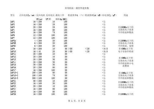
型号正向电流I F(mA)反向电流反向电压 最高工作检波效率η(%)检波损耗Ld(dB)结电容Cj(pF)用途IR(uA)UF(V)频率fp(MHZ)2AP116≤25010150≤12AP216≤25025150≤12AP325≤25025150≤12AP416≤25050150≤12AP516≤25075150≤12AP612≤250100150≤12AP712≤250100150≤12AP8A4≤20020150≤12AP8B6≤20020150≤12AP8C6≤20020150≤12AP916≤2001050≥80≤20≤0.52AP1016≤402050≥80≤20≤0.52AP1125≤2501080≤12AP1225≤2501080≤12AP1320≤2503080≤12AP1420≤2503080≤12AP1530≤2503080≤12AP1620≤2505080≤12AP1716≤25010080≤12AP18-1100≤1005080≤1 2AP18-2150≤1007580≤1 2AP18-3200≤10010080≤1 2AP2150≤25010150≤1 2AP2216≤10030150≤1 2AP2325≤25040150≤1 2AP2416≤25050150≤1 2AP2516≤25050150≤1 2AP2616≤250100150≤1在40MHz以下的无线电电子设备中作检波和整流在100MHz以下的无线电电子设备中作检波和整流在100MHz以下的无线电电子设备中作检波和整流在150MHz以下的无线电电子设备中作检波和整流在150MHz以下的无线电电子设备中作检波、鉴频在40MHz以下的电子设备作检波在40MHz以下的无线电电子设备中作检波和小电流整流第 1 页,共 2 页2AP278≤250150150≤1 2AP2816≤250100180≤1 2AP2916≤25050150≤1 2AP30A10≤5010200≤12AP30B10≤25010200≤1 2AP30C10≤10015200≤1 2AP30D10≤10015200≤1 2AP30E10≤1125200≤1 2AP318≤1025200≤0.3在各种电子设备中作高频检波和在超高频毫伏表中作探头检波在100MHz以下的无线电电子设备中作检波和整流第 2 页,共 2 页。
环刚度12的hdpe双壁波纹管国标壁厚
环刚度12的hdpe双壁波纹管国标壁厚下载提示:该文档是本店铺精心编制而成的,希望大家下载后,能够帮助大家解决实际问题。
文档下载后可定制修改,请根据实际需要进行调整和使用,谢谢!本店铺为大家提供各种类型的实用资料,如教育随笔、日记赏析、句子摘抄、古诗大全、经典美文、话题作文、工作总结、词语解析、文案摘录、其他资料等等,想了解不同资料格式和写法,敬请关注!Download tips: This document is carefully compiled by this editor. I hope that after you download it, it can help you solve practical problems. The document can be customized and modified after downloading, please adjust and use it according to actual needs, thank you! In addition, this shop provides you with various types of practical materials, such as educational essays, diary appreciation, sentence excerpts, ancient poems, classic articles, topic composition, work summary, word parsing, copy excerpts, other materials and so on, want to know different data formats and writing methods, please pay attention!环刚度12的HDPE双壁波纹管国标壁厚解析引言HDPE双壁波纹管作为一种常用的排水管材,其环刚度和壁厚是评估其质量和适用性的重要指标。
12立压缩箱拉臂车技术参数-概述说明以及解释

12立压缩箱拉臂车技术参数-概述说明以及解释1.引言1.1 概述概述12立压缩箱拉臂车是一种用于运输和搬运货物的专用设备。
其设计结构紧凑,操作简便,并且具有较强的承载能力和稳定性。
本文将对12立压缩箱拉臂车的技术参数进行详细介绍,帮助读者更好地了解该设备的性能和特点。
通过分析技术参数,读者可以更好地选择和应用12立压缩箱拉臂车,提高工作效率和运输效果。
"1.2 文章结构"部分内容如下:本文分为引言、正文和结论三部分。
在引言部分,将对12立压缩箱拉臂车技术参数进行概述,介绍文章的结构和目的。
在正文部分,将详细介绍该拉臂车的三个关键技术参数,包括技术参数一、技术参数二和技术参数三。
最后在结论部分,对文章进行总结,探讨该技术在应用领域中的意义,并展望未来的发展方向。
通过这样的结构,读者可以全面了解12立压缩箱拉臂车的技术参数及其潜在应用价值。
1.3 目的本文旨在介绍12立压缩箱拉臂车的技术参数,以便读者了解该设备在使用过程中的性能及特点。
通过详细的参数介绍,读者可以更全面地了解这款设备的功能和适用范围,进而为选购或使用提供参考依据。
同时,通过对该设备技术参数的解析,有助于提高用户对设备的操作和维护技能,从而更好地发挥设备的效能,提高工作效率。
希望本文能为读者提供有益的信息和帮助,使他们能更好地了解和运用12立压缩箱拉臂车。
2.正文2.1 技术参数一12立压缩箱拉臂车是一种用于压缩箱装卸的专用设备,其技术参数包括以下几个方面:1. 载重能力:12立压缩箱拉臂车的主要功能是用于装卸集装箱,因此其载重能力是一个关键参数。
通常情况下,该车的最大承载能力可以达到12吨,能够满足大多数压缩箱装卸的需求。
2. 最大升降高度:为了适应不同高度的卡车或货车,12立压缩箱拉臂车需要具备一定的升降高度。
一般来说,该车的最大升降高度可以达到8米左右,能够满足大多数压缩箱的装卸要求。
3. 额定工作范围:为了确保拉臂车的工作效率和安全性,其额定工作范围也是一个重要的技术参数。
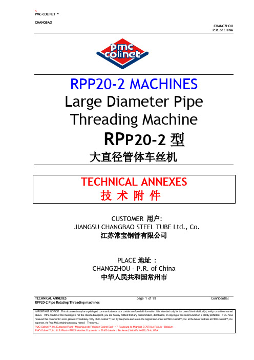
RPP20-2 TECHAN-CHANGBAO 中英文对照
P.R. of CHINARPP20-2 MACHINESLarge Diameter PipeThreading MachineRP P20-2型大直径管体车丝机CUSTOMER 用户:JIANGSU CHANGBAO STEEL TUBE Ltd., Co.江苏常宝钢管有限公司PLACE地址:CHANGZHOU – P.R. of China中华人民共和国常州市TECHNICAL ANNEXES page 1 of 92 Confidential RPP20-2 Pipe Rotating Threading machinesP.R. of CHINATECHNICAL ANNEXES page 2 of 92 Confidential RPP20-2 Pipe Rotating Threading machinesIMPORTANT NOTICE : This document may be a privileged communication and/or contain confidential information. It is intended only for the use of the individual(s), entity, or entities named above. If the reader of this message is not the intended recipient, you are hereby notified that any dissemination, distribution, or copying of this communication is strictly prohibited. If you have received this document in error, please immediately notify PMC-Colinet™, Inc. by telephone and return the original document to PMC-Colinet™, Inc. at the below address at PMC-Colinet™, inc. expense, via Post Mail, retaining no copy hereof. Thank you.P.R. of CHINATECHNICAL ANNEXESpage 3 of 92ConfidentialRPP20-2 Pipe Rotating Threading machinesIMPORTANT NOTICE : This document may be a privileged communication and/or contain confidential information. It is intended only for the use of the individual(s), entity, or entities named above. If the reader of this message is not the intended recipient, you are hereby notified that any dissemination, distribution, or copying of this communication is strictly prohibited. If you have received this document in error, please immediately notify PMC-Colinet™, Inc. by telephone and return the original document to PMC -Colinet™, Inc. at the below address at PMC -Colinet™, inc. expense, via Post Mail, retaining no copy hereof. Thank you. 1-1.Introduction – Project Description 总体介绍-项目说明General Description of the project :The Seller has been approached by the Buyer and the End User to supply two large diameter pipe Threading machines complying with the hereafter requirements.买方和最终用户要求卖方依照以下条件提供两台大直径管体车丝机。
Q81201-Q81212 Optical Power Stabilizers说明书

39Optical Measuring Instruments and Optical Device Test SystemsS t a b i l i t yModelQ81201Q81202Q81203Q81204Q81205Q81206Q81207Q81211Q81212Photoemittion element LED LED LED LED LED Edge-Emitting LED Edge-Emitting LED FP-LD FP-LD Wavelength 850 ± 25 nm 1310 ± 40 nm 1550 ± 30 nm 1310 ± 10 nm 1550 ± 10 nm 1300 ± 30 nm 1550 ± 30 nm 1310 ± 10 nm 1550 ± 20 nm Spectrum Half value 55 nm or less 160 nm or less 210 nm or less 20 ± 5 nm 20 ± 5 nm 100 nm or less 140 nm or less 5 nm or less 10 nm or less Output power -15 ± 1 dBm*1-20± 1 dBm*1-43± 1 dBm*2-35± 1 dBm*1-53± 1 dBm*2-14± 1 dBm*2-17± 1 dBm*20± 1 dBm*20± 1 dBm*2Output power (variable)––––––––– ––––––––––––(23± 1˚C/1min) ––– –––––––––––– ––– –––± 0.01 dB or less± 0.01 dB or less(23± 2˚C/1h)± 0.02 dB or less± 0.02 dB or less± 0.04 dB or less± 0.02 dB or less± 0.04 dB or less–––––– ––––––(Between 0 to 40˚C ± 2˚C/1h) ––– ––––––––– –––± 0.02 dB or less ± 0.04 dB or less ± 0.05 dB or less ± 0.05 dB or less (0 to 40˚C/8h)± 0.2 dB or less± 0.2 dB or less± 0.2 dB or less± 0.2 dB or less± 0.2 dB or less± 0.4 dB or less± 0.4 dB or less± 1 dB or less± 1 dB or lessOutput waveform:CW or chopped light: 270 Hz ( ± 0.1%) with duty of 50 ± 5%, 2 kHz/4 kHz (± 0.1%) with duty of 50 ± 10%Output connector:FC typePreheating time:60 minutes after power on*1 At the photoemittion edge of 2 m fiber (GI 50/125 µm)*2 At the photoemittion edge of 2 m fiber (SM 10/125 µm)0 to -6 dB,0 to -6 dB,in 0.1 dB steps in 0.1 dB steps High-Accuracy, High-Sensitivity and High-Speed Optical Power MeterQ8221●Q8221 Light Source Plug-In Unit SpecificationsOptical Power Measurement Specifications Sensor plug-in channels : 2 (Channels A and B)Resolution:dBm/dB display: 0.001 dB (or 0.0001 dB for data output via GPIB)W display: Max.199,999 counts Measurement mode:CW or chopped light (270 Hz) measurement mode selectable Sensor wavelength sensitivity compensation:If a wavelength is entered, an internal compensation value for the sensor wavelength sensitivity at that wavelength is automatically applied.Relative value measurement (dBr):The value relative to reference value is measured and displayed in dB with a maximum resolution of 0.001 dB (or 0.0001 dB for data output via GPIB).Unit display: W (mW, µW, nW, pW), dBm, dBDisplay of measured value: 5-1/2 digit (7-segment FL Device)Range : Automatic, manual, remote Integration time: 100, 20, 7, or 2 msec.Measurement speed:Approx. 100 measurements/second (with 2-msec. integration time and one-channel operation)Approx. 50 measurements/second (with 7-msec. integration time and one-channel operation)Approx. 30 measurements/second (with 20-msec. integration time and one-channel operation)Approx. 9 measurements/second (with 100-msec. integration time and one-channel operation)Level meter:Displays with up to 11 dots according to measured values.Calculation function:A/B, B/A, and CFW display: Measured values is multiplied by a constant.dBm display: Offset is possible.Maximum hold function: Displays the maximum measured value.Averaging function: The number of averaging can be set to 2 to 256using the running averaging method.Light Source Plug-In Unit Specifications Unit Plug-in channels:2 (Channels A and B)Output power adjustment function:The output power can be set from 0 to -6.0 dB with a setting resolution of 0.1 dB steps.Output mode: CW or chopped light (270 Hz, 2 kHz, or 4 kHz) mode selectable.Other FunctionsRecord function; PDL/PDR* measurement functions: Can store up to 400 measurement data items for each of channels A and B in the backup memory. Stored data items can be read by a personal computer via the GPIB interface. The maximum value, minimum value and the difference of them (Max.-Min.) are displayed.Memory function: Up to five settings can be stored and read for each of channels A and B.Direct plotting function: Measurement data items stored by the record function can be plotted directly to an external plotter in the form of graphs.Connectable plotters:682-XA (Hitachi Electronics)HP7550A (Hewlett-Packard)Brightness adjustment function: The brightness of the display can be adjusted in five steps.Output functions specifications:GPIB interface: IEEE488-1978Analog output: Outputs analog signal which is proportional to the input optical power.Output voltage: 0 to +2 V(F.S.) for each range Output impedance: 0.5 Ω or less Output connector: BNC ConnectorGeneral SpecificationsAmbient temperature: 0 to +40˚C (85%RH or less)Storage temperature: -25 to +70˚CPower requirements: 100 to 240 VAC, 48 to 66 Hz Power consumption:50 VA or less (including the plug-in unit and sensors)Dimensions: Approx. 212 (W) × 88 (H) × 360 (D) mm Mass: 3.9 kg maximum (including the plug-in unit)Standard accessories:Power cable × 1Fuse × 2Instruction manual × 1*PDR: Polarization Dependent Ratio。
二路达林顿管 型号

二路达林顿管型号
摘要:
1.二路达林顿管简介
2.二路达林顿管的型号
3.二路达林顿管的应用领域
正文:
二路达林顿管,是一种电子元器件,主要用于信号放大和开关控制电路中。
它的设计独特,性能稳定,被广泛应用在各种电子设备中。
二路达林顿管有多种型号,常见的有12AX7、12AU7、12AT7 等。
这些型号的不同,主要体现在其工作电压、电流、放大倍数等参数上。
其中,
12AX7 型二路达林顿管是我国使用最广泛的一种,它的工作电压范围宽,放大倍数大,且稳定性好,因此受到了广大电子工程师的青睐。
二路达林顿管的应用领域非常广泛,几乎涵盖了所有的电子设备。
它主要应用于放大电路、滤波电路、振荡电路等,还可以作为开关元件使用。
在音响设备、通信设备、计算机、电视机等电子产品中,都可以看到二路达林顿管的身影。
各种铜管标准及国际对照
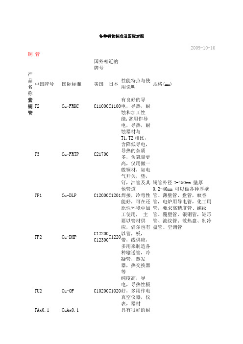
各种铜管标准及国际对照2009-10-16 铜管国外相近的牌号产品名称中国牌号国际标准美国日本性能特点与使用说明规格(mm)紫铜管T2 Cu-FRHC C11000 C1100有良好的导电,导热,耐蚀和加工性能,常用作导电,导热,耐蚀器材与T1,T2相比,含降低导电,导热的杂质多,含氧量更高,仅用做一般铜材,如电气开关,垫,钉,油管及其他管道铜管外径2-450mm 壁厚0.2-40mm 可以做各种厚壁管、薄壁管、盘管,蚊香管,电炉用导电管,化工用管,要求高精度管、螺纹管、覆塑管,银铜管,矩形管、波纹管、散热盘、制冷盘管、空调管T3 Cu-FRTP C21700TP1 Cu-DLP C12000 C1201 焊接,冷弯性能好,可在还原性环境中加工使用,主要以管材供应,偶尔也有以管,板,带,线供应,多用来制造各种输送管,冷凝管,蒸发器,热交换器等TP2 Cu-DHPC12200C12300C1220TU2 Cu-OF C10200 C1020纯度高,导电,导热性极好,多用作电真空仪器,仪表,器材TAg0.1 CuAg0.1 具有很好的耐磨性,电接触性和耐蚀性普通黄铜管H96 CuZn5 C21000 C2100强度低,导热,导电性好,镀锡铜管,各类牌号均可,预镀铜层厚H90 CuZn10 C22000 C2200和H96性能相似,强度稍高,可镀金属,各种给排水管,双金属片及奖章,艺术品等H85 CuZn15 C23000 C2300强度较高,塑性良好,适合冷,热加工焊接性及耐蚀性良好,冷凝和散热用管,蛇形管,虹吸管,冷却设备制件H80 CuZn20 C24000 C2400和H85性能类似,强度较高,塑性也较好,耐蚀性较高,薄壁管,皱纹管造纸网及房屋建筑用品H70 CuZn30 C26000 C2600塑性优良,强度较高,切削加工性好,焊接,耐蚀性好,热交换器,造纸用管,机械,电子零件H68 C26200 性能与H70极相似,但冷作时有,“季裂”倾向,复杂的冷冲件和深冲件,如波H68A CuZn30As C26130纹管 H65CuZn35 C27000 C 2700 有良好的力学性能,能承受冷热加工,用于制作小五金,日用品,螺钉等制件 H63CuZn37 C27200 C 2720 有良好的力学性能,热态下塑性良好,切削性良好,焊接性,耐蚀性良好,各种深引伸和弯折的受力件,如销钉,螺帽,气压表弹簧,散热性,环形件 H62CuZn40 C28000 C 2800 镀银铜管,各类牌号均可,镀锡层厚(μm)≥2,基管规格(mm),宽度10-100厚度0.1-1.0,镀层成分 纯锡(Sn) HPb59是一种广泛应用的铅黄铜,具有良好的力学能,是切削加工性好,可承受冷热压力加工,适用于切削加工及冲压加工的各种结构零件,如垫片,衬套等 环保铜铅黄铜管HPb63-3C34500 C 3450 切削加工性能优良,有高的减摩性能,钟表结构件及汽车拖拉机零件 HPb63-0.1切削加工性略差,结构零件 HPb63-0.8CuZn37Pb1 C35000 C 3710 HPb60-1切削加工性好,强度高,高强度的结构零件 HPb59-1 CuZn39Pb1 C37710 C 3771 是一种广泛应用的铅黄铜,具有良好的力学性能,且切削加工性好,可承受冷热压力加工,使用于切削加工及冲压加工的各种结构零件,如垫片,衬套等HPb59-3HPb89-2HPb66-0.5HPb62-3锡黄铜管HSn70-1有高的耐腐蚀性,有良好的力学性能,在冷,热态下压力加工性良好,可用于舰船上的耐蚀零件及蒸汽,油类等介质接触的零件及导管HSn62-1 CuZn38Sn1C46400C4620HSn60-1C48600力学性能及切削性良好,俗称海军黄铜与海水接触的船舶零件或其他零件HSn90-1C40400具有高的耐蚀性和减摩性,是唯一可用作减摩合金使用的锡青铜,用作耐蚀减磨零件如衬套等铝黄铜管HAL77-2强度高,硬度高,塑性良好,海水中耐蚀性好,但有腐蚀开裂倾向,船舶等用做冷凝管及其他耐蚀零件HAL67-2.5耐磨性好,对海水耐腐蚀性尚好,海轮抗蚀零件HAL60-1-1CuZn39AL-FeMn C67800强度高,冷态下塑性略差,耐蚀性好,腐蚀开裂敏感,用做各种耐蚀结构零件,如齿轮,轴,料套等HAL66-6-3-2具有高强度,硬度及耐磨性,耐蚀性良好,但塑性教差,大型蜗杆及重荷工作条件下的螺母锰黄铜管HMn57-3-1强度,硬度高,但塑性差,耐蚀性好于普通黄铜,耐蚀的结构零件HMn58-2力学性能良好,导电,导热性低,耐腐蚀性好,有腐蚀开裂倾向,耐腐蚀的重要零件及弱电电工业用的零件HMn55-3-1耐腐蚀结构件铁黄铜管HFe59-1-1C67820强度高,韧性好,减摩性良好,耐蚀性高,用来制造腐蚀状态下摩擦工作的结构零件HFe58-1-1强度高,硬度高,塑性差,切削性好,耐蚀性尚好,高强度耐蚀零件硅黄铜管HSi80-3力学性能良好,切削性良好,易焊接和钎焊,导电,导热性低,耐蚀性高,无腐蚀开裂倾向,船舶用零件,蒸汽及水管及管配件镍黄铜管HNi65-5力学性能良好,切削性好,易焊接和钎焊,导电,导热性低,耐蚀性高,且无腐蚀开裂倾向,船舶用零件,蒸汽及水管及配件锡青铜管QSn4-3CuSn4Zn2高的耐摩性,弹性,抗磁性良好,化工设备的耐蚀件,耐磨件,弹簧及各种弹性元件,抗磁元件QSn4-4-2.5高的耐摩性,良好的切削性,焊接性,主要用来制造摩擦条件下工作的轴承轴套,衬套及圆盘等QSn4-4-4CuSnPb4Zn3C54400QSn6.5-0.1CuSn6C51900C5191QSn6.5-0.4CuSn7C51900C5191因含磷量较QSn6.5-0.1要高,抗疲倦强度,弹性,耐磨性均教好,除用作弹簧及耐磨件外,主要用于制造造纸工业用的耐磨铜网 QSn7-0.2 CuSn8C52100 C 5210 强度高,弹性,耐磨性好,焊接性好耐蚀性好,制作中等负荷,中等滑动速度下承受摩擦的零件,如轴承,轴套,蜗轮等 QSn4-0.3 具有高的力学性能,耐腐蚀性和高弹性,多用制作各种压力计用管材料QSn8-0.3QSn1.5-0.2铝青铜管 QAL9-2 CuAl9Mn2 既有高强度,热态,不易钎焊,制作弹簧及其他耐蚀元件,如蜗轮等QAL9-4 CuAl10Fe3C62300 QAL9-5-1-1C628 QAL10-5-5C63280 C 6301 QAL10-3-1.5 C63200 具有高的强度及耐摩擦性,不易钎焊,有较高抗氧化性和耐蚀性,制作高温条件下的耐磨件和标准件,如齿轮,轴承,飞轮QAL10-4-4 CuAl10Ni5Fe5 C63300 C A104 具有高强度,高温力学性能两好,良好的减摩性,不易钎焊,抗蚀性良好,制作高强的耐磨零件和高温条件下工件,如轴衬,轴套,法兰盘,齿轮及其他重要耐蚀零件,耐磨零件铍青铜管QBe2 CuBe2 C17200 C1720是一种理论化综合性能优良的合金,热处理后具有高的强度,硬度,弹性,耐磨性,耐热性和耐寒性,无磁性,易于焊接,且抗蚀性良好QBe1.7 CuBe1.7 C17000 C1700与QBe2性能相近,但在弹性,迟滞性,疲劳强度,弹性稳定性QBe1.9硅青铜管QSi1-3强度高,耐磨性极好,切削性,焊接性良好,耐腐蚀性良好,工作条件较差或腐蚀性介质中的零件制造QSi3-1 CuSi3Mn1C65500C65800强度高,弹性,耐磨性,塑性均好,用于制造腐蚀介质中工作的弹性元件。
- 1、下载文档前请自行甄别文档内容的完整性,平台不提供额外的编辑、内容补充、找答案等附加服务。
- 2、"仅部分预览"的文档,不可在线预览部分如存在完整性等问题,可反馈申请退款(可完整预览的文档不适用该条件!)。
- 3、如文档侵犯您的权益,请联系客服反馈,我们会尽快为您处理(人工客服工作时间:9:00-18:30)。
300
Thermal Characteristics
Symbol
Parameter
RθJC RθJA
Thermal Resistance, Junction-to-Case Thermal Resistance, Junction-to-Ambient *
RθJA
Thermal Resistance, Junction-to-Ambient
Figure 5. Capacitance Characteristics
Capacitance [pF]
©2000 Fairchild Semiconductor International
-VGS, Gate-Source Voltage [V]
-IDR , Reverse Drain Current [A]
©2000 Fairchild Semiconductor International
Rev. A, May 2000
元器件交易网
FQB12P20 / FQI12P20
-ID, Drain Current [A]
Typical Characteristics
DS(on) R [Ω], Drain-Source On-Resistance
-ID , Drain Current [A]
101
100 10-1
2
150℃
25℃
-55℃
※ Notes : 1. VDS = -40V 2. 250μs Pulse Test
4
6
8
10
-VGS , Gate-Source Voltage [V]
Figure 2. Transfer Characteristics
--
20
50
ns
-- 195 400
ns
--
40
90
ns
(Note 4, 5)
--
60 130
ns
VDS = -160 V, ID = -11.5 S = -10 V
-- 8.1
--
nC
(Note 4, 5)
--
16
--
nC
Drain-Source Diode Characteristics and Maximum Ratings
Test Conditions
Min Typ Max Units
Off Characteristics
BVDSS ∆BVDSS / ∆TJ
Drain-Source Breakdown Voltage
Breakdown Voltage Temperature Coefficient
VGS = 0 V, ID = -250 µA
(Note 2)
Avalanche Current
(Note 1)
Repetitive Avalanche Energy
(Note 1)
Peak Diode Recovery dv/dt
(Note 3)
Power Dissipation (TA = 25°C) * Power Dissipation (TC = 25°C)
IS
Maximum Continuous Drain-Source Diode Forward Current
--
-- -11.5
A
ISM
Maximum Pulsed Drain-Source Diode Forward Current
--
--
-46
A
VSD
Drain-Source Diode Forward Voltage VGS = 0 V, IS = -11.5 A
D
S
!
GS
D2-PAK
FQB Series
GDS
I2-PAK
FQI Series
Absolute Maximum Ratings TC = 25°C unless otherwise noted
Symbol VDSS ID
IDM VGSS EAS IAR EAR dv/dt PD
TJ, TSTG TL
Features
• -11.5A, -200V, RDS(on) = 0.47Ω @VGS = -10 V • Low gate charge ( typical 31 nC) • Low Crss ( typical 30 pF) • Fast switching • 100% avalanche tested • Improved dv/dt capability
Coss
Output Capacitance
Crss
Reverse Transfer Capacitance
VDS = -25 V, VGS = 0 V, f = 1.0 MHz
-- 920 1200 pF
-- 190 250
pF
--
30
40
pF
Switching Characteristics
td(on)
-200 --
ID = -250 µA, Referenced to 25°C --
-
IDSS
Zero Gate Voltage Drain Current
VDS = -200 V, VGS = 0 V VDS = -160 V, TC = 125°C
--
--
--
--
IGSSF IGSSR
Gate-Body Leakage Current, Forward VGS = -30 V, VDS = 0 V Gate-Body Leakage Current, Reverse VGS = 30 V, VDS = 0 V
元器件交易网
FQB12P20 / FQI12P20
FQB12P20 / FQI12P20
200V P-Channel MOSFET
May 2000
QFETTM
General Description
These P-Channel enhancement mode power field effect transistors are produced using Fairchild’s proprietary, planar stripe, DMOS technology. This advanced technology has been especially tailored to minimize on-state resistance, provide superior switching performance, and withstand high energy pulse in the avalanche and commutation mode. These devices are well suited for high efficiency switching DC/DC converters.
Parameter
Drain-Source Voltage
Drain Current
- Continuous (TC = 25°C) - Continuous (TC = 100°C)
Drain Current - Pulsed
(Note 1)
Gate-Source Voltage
Single Pulsed Avalanche Energy
--
--
-5.0
V
trr
Reverse Recovery Time
Qrr
Reverse Recovery Charge
VGS = 0 V, IS = -11.5 A,
-- 180
--
ns
dIF / dt = 100 A/µs
(Note 4)
--
1.44
--
µC
Notes:
1. Repetitive Rating : Pulse width limited by maximum junction temperature 2. L = 9.2mH, IAS = -11.5A, VDD = -50V, RG = 25 Ω, Starting TJ = 25°C 3. ISD ≤ -11.5A, di/dt ≤ 300A/µs, VDD ≤ BVDSS, Starting TJ = 25°C 4. Pulse Test : Pulse width ≤ 300µs, Duty cycle ≤ 2% 5. Essentially independent of operating temperature
101
100
10-1 0.0
150℃ 25℃
※ Notes : 1. V = 0V
GS
2. 250μs Pulse Test
0.5
1.0
1.5
2.0
2.5
3.0
-VSD , Source-Drain Voltage [V]
Figure 4. Body Diode Forward Voltage Variation vs. Source Current and Temperature
VDS = VGS, ID = -250 µA
-3.0 --
-5.0
V
VGS = -10 V, ID = -5.75 A
-- 0.36 0.47
Ω
VDS = -40 V, ID = -5.75 A (Note 4)
--
6.4
--
S
Dynamic Characteristics
Ciss
Input Capacitance
V/ns W W
W/°C °C °C
