DMN500-48电源技术规格书V2.03
铁塔电源培训教材

2.2、系统配置
2.3、交流配电单元
输入接口 交流输入断路器 交流中线排 接地汇流排 相应功能 1路,用于交流电源的输入。三相交流电源的相线去皮后以裸压方式分别接入断 路器上方的3个接线端子。 接入交流电源的零线(中线)。 接入到机房的接地排上。
模块交流输入断 路器
交流输入断路器
注:交流输入形式(单路、两路手动转换)可以根据需求 进行选配;交流输出分路、交流插座等需求可以根据用户实 际需要进行配置
g.
2.6 控制器外观
2.6.1 DKD48-Ⅱ型控制器外观图 (正面)
↑ 上键 在数值修改时为“增加”键,其它状态为“ 向上”选择键 ↓ 下键 在数值修改时为“减少”键,其它状态为“ 向下”选择键 确认键 进入下一级菜单,或者进入数值修改状 态,或者确认数值存储 C 退出键 返回上级菜单,或者放弃数值更改
第二章 系统组成
2.1 系统组成框图 2.2 系统配置 2.3 交流配电单元 2.4 直流配电单元 2.5 整流器 2.6 控制器 2.7系统检测
2.1、DUM-48/50H系列铁塔智能开关电源系统组成原理框图
交流输入 交流配电 整流器 直流配电 电池/负载
转接板
环境量/直流分路检 测
DKD48-Ⅱ控 制器
1.3.1使用环境
1.3.1使用环境
工作环境温度:-5~+40℃; 工作相对湿度:≤90%(40±5℃)(无凝露); 贮存环境温度:-40~+70℃; 贮存相对湿度:≤95%(40±5℃)(无凝露); 大气压力(海拔):70~106kPa(海拔:0~3000m)。 注:海拔高度2000m以上使用环境条件下系统应降额使用,海拔 每升高200m,则工作环境温度降低1℃。 振动:系统能承受频率为(10~55)Hz 、振幅为0.35mm的正弦波 振动; 冲击:整流模块能承受峰值加速度为150m/s2, 持续时间11ms; 日晒:具有防晒隔热措施,能承受1120W/M2等级太阳辐射。 机房应无严重尘土、爆炸性危险介质、腐蚀金属和破坏绝缘的有 害气体、导电微粒和严重的霉菌,无强电磁场干扰。
超低电压大电流直流电子负载

1.2.
主要特点 ............................................................................................................ 1
1.3.
主机面板介绍 .................................................................................................... 2
2.6.2. 控制连接 ............................................................................................................ 6
2.6.3. 采样连接 ............................................................................................................ 6
3.1.
控制模式 ............................................................................................................ 8
3.2.
恒电流测试功能(CC) ................................................................................... 8
2.6.
连接方式 ............................................................................................................ 5
DUM-4825D4系列电源说明书-V104-070120
邦普DM500A模块机组控制器说明书.
PUNP ELECTRONICDM500A模块板机组控制器厂家使用说明书在安装使用控制器之前,请详细阅读该使用说明书!邦普电脑技术开发有限公司2004/07/21软件功能码:DM500A-QHTH-F01M V1.02版权所有,翻版必究!目录一、概述 (1)二、控制器操作框架 (1)三、安装说明 (1)1、外观图 (1)2、外形安装尺寸图 (2)3、模块板的设置说明 (3)4、电源通讯连接示意图 (4)四、界面及操作说明 (5)1、用户操作 (5)(1)开机显示 (5)(2)用户主界面显示 (5)(3)用户查询操作 (6)(4)用户设置 (8)(5)参数设置 (9)2、控制逻辑 (12)(1)开机操作 (12)(2)停机操作 (12)(3)能量调节 (12)(5)故障制约关系 (13)(6)运行指示 (13)(7)报警指示 (13)(8)远程开关 (14)3、故障处理 (14)五、运行参数设置 (15)六、相关逻辑 (18)1、冬季防冻逻辑 (18)2、除霜逻辑 (18)3、电加热控制 (19)4、保护 (19)(1)、压缩机保护 (19)(2)、其他保护 (19)七、故障诊断 (19)1、故障显示 (19)2、故障编号及说明 (19)3、故障可能原因表 (20)附录1:风冷送水电气连接图 (22)附录4:版本更改说明 (23)一、概述控制器采用先进的、高集成度的一体化单片机,极大的提高了系统的抗干扰能力。
外型采用塑料外壳,安装方便。
前后板通过485通讯方式进行数据交换,整个系统既可以一体化安装,也可以进行分体式安装。
二、控制器操作框架三、安装说明1、外观图图 3-1开机画面厂家测试用户主监控界面用户查询操作 用户设置操作参数设置当前故障查询压机运行时间查 询系统时间查询 定时开停设置 初始化参数运行参数设置历史故障查询模块禁用设置修改密码系统时间设置 运行时间设定模块状态查询 强制 除霜面板正面如(图3-1)所示, 面板的外形尺寸为:长196mm×宽115.5mm。
应用手册:逆相电源扩展器PE500说明书

PE500, ILLUMATECH IP710, REVERSE PHASE DIMMED FIXTURES
UL924 BYPASS, PE500, ILLUMATECH IP710, REVERSE PHASE DIMMED FIXTURES
PE500, RENOIR II, REVERSE PHASE DIMMED FIXTURES
ABBREVIATIONS LC Luma-CAN LV Low Voltage HV High Voltage Switch (Maintained) LVM Low Voltage Switch (Momentary)
Equal to Leviton: 1081 (Toggle) or 56081 (Decora) LVT Low Voltage Switch (Maintained) Equal to Leviton: 12021-2 (Toggle) or 56021-2 (Decora) LV2 IRC Low Voltage Switch Equal to Leviton: RLVSW-1LW (1 button) or RLVSW-2LW (2 button) or RLVSW-4LW (4 button)
5. Line voltage load not to exceed contact rating per device specifications.
6. Power packs receiving separate feeds for switched loads and self power must have both feeds on the same phase
22. Control Receptacle: • Quantity per applicable codes • Termination shown split receptacle. Termination per applicable codes. • Receptacle markings per applicable energy codes
长城电源技术规格书说明书
电源技术规格书(客户承认书)SPECIFICATION FOR APPROV AL客户/ CUSTOMER: 光电显示客户物料号/CUSTOMER NO.:长城型号/ MODEL NO.: XSP200WV42B长城料号/ P/N .: 5171915电源版本/ POWER REV.: V01日期/ DATE: 2020.02.27客户确认签字,盖章后请回传一份承认书给我司。
Please return to us on copy of “SPECIFICATION FOR APPROV AL”with your approved signature.中国长城科技集团股份有限公司电源事业部China Greatwall Technology Group Co., LTD. Power Supply Division深圳宝安区石岩镇宝石东路长城工业园Great wall Industry Park, Baoshi East Rd, Shiyan Country, Baoan, ShenzhenTEL: 0755--29519374 / 26639997 FAX: 0755--29519395/power变更记录目录总则 (2)1 电气特性 (2)1.1输入特性 (2)1.1.1输入基本特性 (2)1.1.2输入保护特性 (2)1.2 输出特性 (2)1.2.1输出基本特性 (2)1.2.2输出保护特性 (3)1.2.3负载/温度曲线图&负载/输入电压曲线图 (3)2 环境 (4)3 电磁兼容性 (4)4 安规 (4)5 可靠性 (4)6 特殊要求 (4)7 外观结构 (5)7.1电源尺寸 (5)7.2标签图 (6)8 包装 (6)8.1电源净重 (6)8.2包装图 (6)8.3包装运输实验 (7)9条形码label说明 (7)10 使用注意事项 (8)10.1开箱检查 (8)10.2使用原则 (8)10.3安全注意事项 (8)11 产品保修 (8)11.1保修期限 (8)11.2维修范围 (8)11.3限制条款 (9)12 备注 (9)总则该款产品为AC转DC电源,90~264Vac交流输入,单路直流隔离输出,输出总功率168W,通过CCC、CE、UL认证,符合欧盟RoHS指令。
TMN20H-400技术规格书(中文版)

TMN20H-400 8英寸纳滤膜元件技术规格书TMN膜是东丽公司最新研制开发的超低压型芳香族聚酰胺复合纳滤膜,它具有超低的运行压力(较常规纳滤膜的运行压力降低了50%以上);中到高的脱盐率(处理水中保持一定的矿物度,保持口感);高的硅透过率(不必担心浓缩水中的硅垢表面污染);高通水量(通过改善膜元件结构增加了产水量)等优点。
TMN20H-400膜元件适合于以地表水和大多数井水为水源的市政用水的硬度软化、色度净化等高度处理,是专门设计用于脱除盐分、硝酸盐、杀虫剂、除草剂、THM前驱物质等有机化合物、细菌和病毒。
也适合于中小规模的锅炉补给水等各种工业用水,饮料水制造在内的多种应用领域,能为客户带来显著的节能效益。
1、膜元件性能规范膜元件型号标准脱盐率% 透过水量gpd (m3/d) 有效膜面积ft2 (m2)(45.5) 400 (37)TMN20H-400 95.0-99.0 12,000测试条件:操作压力100 psi (0.69MPa)测试液温度 77゚F (25℃)测试液浓度500 mg/l (as NaCl)单只膜元件水回收率 15%测试液pH 7单支膜元件最低脱盐率 95.0%最小透过水量9,600 gpd (36m3/d)2、使用极限条件最高操作压力·············································································365psi (2.5MPa)最高进水流量·············································································70gpm(380m3/d)最高进水温度·············································································113゚F(45℃)最大进水SDI (5)进水自由氯浓度··········································································检测不到连续运行时进水pH范围·······························································2-11化学清洗时进水pH范围·······························································1-12单个膜元件最大压力损失······························································15psi (0.10 MPa)单个膜组件最大压力损失······························································50psi (0.34MPa)3、膜元件尺寸图示所有的单位为:英寸(毫米)。
DMN500-48电源技术规格书V2.03
活化 开关 按 电池 键 开关
端子
电源状态指示 充电:绿色,电池充电指示,电池充电时亮,电池放电或电池活化时熄灭; 放电:红色,电池放电指示,电池放电或电池活化时亮,电池充电及电池放电结束时熄灭; 活化:黄色,电池活化时亮,否则熄灭; 欠压:红色,电池或电源输出欠压时亮,否则熄灭; 故障:红色,电源输出过压,模块过温,过冲保护,或电池反接时(有交流电时)亮;冲击 负载时,无点亮,无闪烁,达到60S限时后自动关闭AC/DC。
二技术参数dmn50048技术参数表输入特性项目测试条件最小典型最大输入电压范围vac输出满载165220265输入电压范围vdc输出满载200300375频率hz交流输入405060输出特性项目测试条件最小典型最大输出电压vac全范围输入均充55456566ac全范围输入浮充53454546ac失电电池供电4257输出电流a全范围输入不含充电电流环境温度为253843全范围输入不含充电电流环境温度为5511全范围输入冲击电流5a125a60s关闭acdc20分钟重启125dmn50048充电电源技术规格书全范围输入冲击电流125a18a20s关闭acdc20分钟重启18冲击负载限时s全范围输入功率500w20纹波噪声mvpp全范围输入典型负载500源效应ac全范围输入典型满载05负载效应ac典型输入负载在10100之间变化10电池恒流充电电流aac全范围输入典型负载0606507充电电流精度vi165265vac典型负载电池放电关断点v典型负载414243电池活化完成点v典型负载444546电池欠压告警点v典型负载434445电池放电关断延时s典型负载304560电池放电回路内阻放电电流25a电池最大放电电流a放电时间60s30活化触点接触时间s遥控活化启动退出0510遥控电池退出0515输出过压保护v关断输出596061输出短路保护ac全范围输入关断电源输出撤销自动重启动一般特性项目测试条件最小典型最大温度系数005绝缘电阻m输入对输出50输入对机壳50输出对机壳50相对湿度40290效率ac典型输入典型负载电池充满压vac漏电流5ma工频50hz1min无击穿输入对输出2500输入对机壳2500输出对机壳2500外形尺寸168mm45mm工作环境温度4070工作壳温4085存储温度40105重量kg平均无故障时间h室温条件下80000dmn50048充电电源技术规格书三emc电磁兼容雷击浪涌干扰测试方法及要求
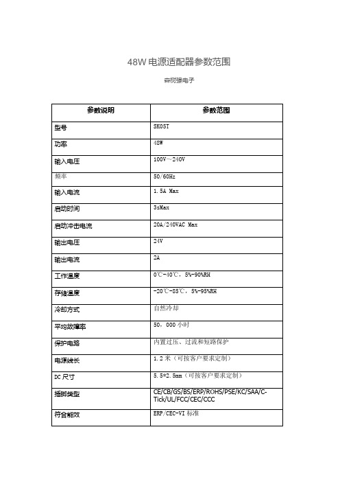
48W电源适配器参数范围
IEC60950-1 AS/NZS 60950.1, AS/NZS CISPR 22, AS/NZS 4665;IEC 61558, AS/NZS 61558, AS/NZS CISPR 14
冷却方式
自然冷却
平均故障率
50,000小时
保护电路
内置过压、过流和短路保护
电源线长
1.2米(可按客户要求定制)
DC尺寸
5.5*2.5mm(可按客户要求定制)
插脚类型
CE/CB/GS/BS/ERP/ROHS/PSE/KC/SAA/C-Tick/UL/FCC/CEC/CCC
符合能效
ERP/CEC-VI标准
48W电源适配器参数范围
森树强电子
参数说明
参数范围
型号
SK05T
功率
48W
输入电压
100V~240V
频率
50/60Hz
输入电流
1.5A Max
启动时间
3sMax
启动冲击电流
20A/24Байду номын сангаасVAC Max
输出电压
24V
输出电流
2A
工作温度
0℃-40℃,5%-90%RH
存储温度
-20℃-85℃,5%-95%RH
48w电源适配器参数范围森树强电子参数说明参数范围型号sk05t功率48w输入电压100v240v频率5060hz输入电流15amax启动时间3smax启动冲击电流20a240vacmax输出电压24v输出电流2a工作温度040590rh存储温度2085595rh冷却方式自然冷却平均故障率50000小时保护电路内置过压过流和短路保护电源线长12米可按客户要求定制dc尺寸5525mm可按客户要求定制插脚类型cecbgsbserprohspsekcsaactickulfcccecccc符合能效erpcecvi标准安规标准iec609501asnzs609501asnzscispr22asnzs4665
不间断电源技术要求

不间断电源额定容量20KV/16kw、后备供电2小时、工频(内置输出隔离变压器)、三进单出不间断电源一套(包括主机、电池、电池柜含开关、铜鼻子、线以及底座承重支架等)。
技术参数表:★额定容量20KVA(VA)★工作方式三进单出工频双变换在线式输入输入电压范围304~456V AC三相四线输入输入频率范围50Hz/60Hz±5%频率跟踪速率1Hz/s输入功率因数﹥0.97最大输入电流32A输出输出电压范围220V AC±1%或230V AC±1%输出频率范围50Hz/60Hz±0.5%(电池模式)功率因数0.8波形失真度线性负载<1%过载能力过载125% 延时10分钟,过载150%延时1分钟峰值系数3∶1(max)暂态电压电压最大变化±4%内(100%负载投入或切离)瞬变响应恢复时<40ms间转换时间★市电模式→电0ms池模式电池★直流电压192VDC充电时间8~10小时内完成90%容量★整机效率>90%面板显示LED 指示电池低压,市电状态,逆变,旁路,UPS异常,过载指示LCD 显示输入输出电压,频率,电池电压,负载百分比,机内温度通讯通讯界面RS232通讯界面SNMP网络界面(选件)工作环境工作温度0~40℃湿度0~95%不结露储藏温度-25℃~55℃噪音<55dB(距箱体1米处)物理特性净重(Kg)297毛重(Kg)337尺寸(W×D×H)mm725×430×1180执行标准YD/T1095-2008蓄电池★后备延时时间(满载)≥2小时有效容量开始使用100%使用1~2年90%使用4年后70~80%自放电速率25℃存放12个月,容量>60% 深充深放循环次数100%,≥180次可存放时间>4个月深度放电保护具备电池状态检测具备电池放电实时监测及显示具备充电时间8小时之内充到电池容量的90%电池保护具备厂商项目授权书、质保承诺函要求提供厂家设备服务承诺书原件(承诺本项目的整套设备的质保期为三年免费);要求提供针对本项目的厂家授权书原件。
SilverStone GEMINI GM500-G 双重备用电源说明书
GM500-GGEMINI SERIESEndless power through redundancy500+500W 24hour fully continuous power outputPS2 mini redundant power with 150mm(W) x 85mm(H) x 180mm(D)80 PLUS Gold Certified Active PFC (full range)1+1 redundant configurationHot swappable designConvenient pull-out handle barsIndustry-leading reliabilitySupport PMBus 1.2The following manual and guides were carefully prepared by the SilverStone engineering team to help you maximize the potential of your SilverStone product. Please keep this manual for future reference when upgrading or performing maintenance on your system. A copy of this manual can also be downloaded from our website at:Installation and system optimization guide:SpecificationGeneralAC input specificationsDC output specification ProtectionEnvironmental requirements Agency requirements Redundant power supply function PMBusReliabilityPhysical characteristics size P.1 P.1 P.1 P.2 P.5 P.6 P.6 P.7 P.8 P.12 P.12SPECIFICATIONSilverStone GEMINIGM500-GMini Redundant Switching Power Supply80 PLUS Gold PMBus 1.2500W+500W01This is the specification of Model GM500-G; it is intended to describe the functions and performance of the mini redundant power supply. The GM500-G 500 watts mini redundant power supply is featured with Active PFC (Power Factor Correction) capability and gold efficiency for 80+ and PMBus function meets IEC61000-3-2 and equips full range Input features.The power supply must meets inrush requirements of any rated AC voltage, during turn on at any phase of voltage, during a single cycle AC dropout condition, during repetitive On/Off cycling of AC, and over the specified temperature range. The peak inrush current shall be 30/60A @ 115/230 VAC (25 ) per module when cold start and less than the rating of its critical components (including input fuse, bulk rectifiers, and surge limiting device).The power supply must operate within all specified limits over the input voltage range in Table 1.Harmonics distortion of up to 10% THD must not cause the power supply to go out of specified limits.Base on the minimum voltage and power transfer, the max current calculation as below:Table 1 – AC Input Voltage and FrequencyMax Current (Watt / Efficiency) / Minimum Voltage2.2 AC inrush current2.1 AC input voltage, frequency and current (Rating: 100V-240 VAC, 47-63Hz, 8-4A)1. General2. AC input specificationsParameter Voltage (115V)Voltage (230V)FrequencyMinimum 90 VAC 180 VAC 47 HzNormal 100-120 VAC 200-240 VAC 50 / 60 HzMaximum 132 VAC 264 VAC 63 HzMax. Current8A 4A N/A022.3 Input power factor correction (Active PFC)The power factor at 50% load shall be 0.9 at 230V input voltage.2.4 Input current harmonicsWhen the power supply is operated in 90-264 VAC of Sec. 2.1, the input harmonic current drawn on the power line shall not exceed the limits set by IEC61000-3-2 Class A and GB17625.1 standards. The power supply shall incorporate universal power input with active power factor correction.2.5 DropoutAn AC line dropout of 17mS or less shall not cause any tripping of control signals or protection circuits. If the AC dropout lasts longer than 17mS, the power supply should recover and meet all turn on requirements. The power supply shall meet the regulation requirement over all rated AC voltages, frequencies, and output loading conditions. Any dropout of the AC line shall not cause damage to the power supply. An AC line dropout is defined as a drop in AC line to 0 VAC at any phase of the AC line for any length of time.3.1 Output current / loading3.2 DC voltage regulation, ripple and noiseThe following table defines power and current rating. The power supply shall meet both static and dynamic voltage regulation requirements for minimum load condition.The power supply output voltages must stay within the following voltage limits when operating at steady state and dynamic loading conditions. All outputs are measured with reference to the return remote sense (Returns) signal. The +5V, +3.3V, +12V, -12V and +5VSB outputs are measure at the power supply connectors references to Returns. The +5V and +3.3V is measured at its remote sense signal (+5VS, +3.3VS) located at the signal connector.Table 2– Output Loads Range 1Note 1: Maximum continuous total DC output power should not exceed 550W.3. DC output specificationOutput Voltage Max. Load Min. Load Max. Combined T otal Output+5V 25A 1A170W500W+3.3V 25A 1A+12V 41A 1A --12V 0.8A 0A -+5VSB 3.5A 0.1A 17.5WTable 3 – Regulation, ripple and noiseOutput Voltage Load Reg.Line Reg.Ripple & Noise+5V +/-5 +/-1 50mV+3.3V +/-5 +/-1 50mV+12V +/-5 +/-1 120mV-12V +/-5 +/-1 120mV+5VSB +/-5 +/-1 50mV03These are the timing requirements for the power assembly operation. The output voltages must rise from 10% to within regulation limits (Tvout_rise) within 5 to 70mS. The +5V, +3.3V and +12V output voltages should start to rise at about the same time. All outputs must rise monotonically. The +5V output must occur first than the +3.3V output during any point of the voltage rise. The +5V output must never be greater than the +3.3V output by more than 2.25V. Each output voltage shall reach regulation within 50 ms (Tvout_on) of each other during turn on of the power supply. Each output voltage shall fall out of regulation within 400 mS (Tvout_off) of each other during turn off. Figure 1 and figure 2 shows the turn on and turn off timing requirement. In Figure 2, the timing is shown with both AC and PSON# controlling the on/off of the power supply.Ripple and Noise shall be measured using the following methods:a) Measurements made differentially to eliminate common-mode noise.b) Ground lead length of oscilloscope probe shall be 0.25 inch.c) Measurements made where the cable connectors attach to the load.d) Outputs bypassed at the point of measurement with a parallel combination of 10uF tantalum capacitor in parallel with a 0.1uF ceramic capacitors.e) Oscilloscope bandwidth of 0 Hz to 20MHz.f) Measurements measured at locations where remote sense wires are connected.g) Regulation tolerance shall include temperature change, warm up drift and dynamic load.3.3 Timing requirementsTable 4 – Output Voltage TimingItem Tvout_riseTvout_on Tvout_offDescription Output voltage rise time from each main output.(+5Vsb < 70mS)All main output must be within regulation of each other within this time.All main output must leave regulation within this timeMIN 5N/A N/AMAX 7050400Units mS mS mSFigure 1:Output Voltage Timing043.4 Remote On/Off Control: PSON#The PSON# signal is required to remotely turn on/off the power supply. PSON# is an active low signal that turns on the +5V, +3.3V, +12V,-5V and –12V power rails. When this signal is not pulled low by the system, or left open, the outputs (except the +5VSB and V bias) turn off. This signal is pulled to a standby voltage by a pull-up resistor internal to the power supply.Table 5 – Turn On/Off TimingItemT sb_on-delayT ac_on-delay Tvout_holdup Tpwok_holdup Tpson_on_delay Tpson_pwok Tpwok_on Tpwok_off Tpwok_low T sb_vout MIN N/AN/A 18175N/A 100110050MAX 15002500N/A N/A 40050500N/A N/A 1000Units mSmSmSmSmSmSmSmSmSmSDescriptionDelay from AC being applied to +5VSB is being within regulation.Delay from AC being applied to all output voltages being Within regulation.All main output voltage stay within regulation after loss of ACDelay from loss of AC deassertion of PWOK.Delay from PSON# active to output voltage within regulation limits.Delay from PSON# deactive to PWOK being deasserted.Delay from output voltage within regulation limits to PWOK asserted at turn on.Delay from PWOK deasserted to output voltages (+5V , +3.3V , +12V) dropping out of regulation limits.Duration of PWOK being in the deasserted state during an off/on cycle using AC or the PSON# signal.Delay from +5VSB being in regulation to O/Ps being in regulation at AC turn on.Table 6 – PWOK Signal CharacteristicSignal TypePSON# = Low PSON# = HighAccepts an open collector/drain input from the system. Pull-up to VSB located in power supply.Power ON Power OFF05The efficiency should be measured module at 230 VAC and with external fan power source at specified loading.3.5 Efficiency (80+ Gold)The +5VSB output is always on (+5V Standby) when AC power is applied and power switch is turned on. The +5VSB line is capable of delivering at a maximum of 3.5A for PC board circuit to operate.3.6 +5VSB (Standby)The OPP function shall work at 110%~160% of rating of output power, then all outputs shut down in a latch off mode. The latch shall be cleared by toggling the PSON# signal or by cycling the AC power. The power supply shall not be damaged from repeated power cycling in this condition. If only one module works inside the power supply, the OPP is at 110%~160% of rating of power supply.4.1 Over power protectionEach hot swap module has respective OVP circuit. Once any power supply module shut down in a latch off mode while the output voltage exceeds the over voltage limit shown in Table 7, the other modules should deliver the sufficient power to the device continually.4.2 Over voltage protectionInput Voltage 230 VAC20% Load 88%50% Load 92%100% Load88%Reference all test conditions.Voltage +5V +3.3V +12V 5VSBMinimum +5.7V +3.9V +13.3V +5.7VMaximum +6.5V +4.5V +14.5V +6.5VShutdown ModeLatch Off Latch Off Latch Off Auto recoveryTable 7 –Over Voltage protectionProtection circuits inside the power supply shall cause only the power supply’s main outputs to shutdown. If the power supply latches off due to a protection circuit tripping, either an AC cycle OFF for 15 sec or PSON #cycle HIGH for 1 sec must be able to restart the power supply.4. Protection064.3 Over current protectionThe power supply should contain the OCP function on each hot swap module. The power supply should be shut down in a latch off mode while the respective output current exceeds the limit as shown in Table 8. When the latch has been cleared by toggling the PSON# single or cycling the AC input power. The power supply module should not be damaged in this condition.4.4 Short circuit protection5.1 Temperature5.2 Humidity6.1 Safety (Planning)6.2 AC Input leakage currentThe power supply shall shut down in a latch off mode when the output voltage is short circuit.Input leakage current from line to ground will be less than 3.5mA rms. Measurement will be made at 240 VAC and 60Hz.Operating T emperature Range:Non-Operating T emperature Range:0°C ~ 40°C -20°C ~ 70°CVoltage +5V +3.3V +12VMinimum 110%110%110%Maximum 160%160%160%Shutdown ModeLatch Off Latch Off Latch OffTable 8 –Over Current protection5. Environmental requirements6. Agency requirementsOperating Humidity Range:Non-Operating Humidity Range:20% ~ 90%RH non-condensing 5% ~ 95%RH non-condensingProduct Safety:UL60950-1/CSA 60950 (USA/Canada)TÜV (CB) IEC60950 (report to include all country national deviations)EN60950-1(Europe)/IEC60950-1(International)FCC(USA)CE-low voltage directive 2006/95/EC(Europe)7. Redundant power supply function7.1 RedundancyThe redundant power supply is N+1=N (500W+500W=500W) function power supply, each one module is redundancy when any one module was failed. To be redundant each item must be in the hot swap power supply module.7.2 Hot swap requirementsThe redundant power supply modules shall be hot swappable. Hot swapping a power supply is the process of inserting and extracting a power supply from an operating. During this process the output voltage shall remain within the limits specified in Table 7 with the capacitive load specified Table 9. The Sub-system shall not exceed the maximum inrush current as specified in section 2.2. The power supply can be hot swapped by the following methods:AC connects with each module. Up to two power supplies may be on a single AC power source. Extraction: The AC power will be disconnected from the power supply first and then the power supply is extracted from the sub-system. This could occur in standby mode or powered on mode. Insertion: The module is inserted into the cage and then AC power will be connected to the power supply module.For power modules with AC docking at the same time as DC. Extraction: The module is extracted from the cage and both AC and DC disconnect at the same Time. This could occur in standby or power on mode. No damage or arcing shall occur to the DC or AC contacts which could cause damage. Insertion: The AC and DC connect at the same time as the module is inserted into the cage. No damage to the connector contacts shall occur. The module may power on or come up into standby mode.Many variations of the above are possible. Supplies need to be compatible with these different variations depending upon the sub-system construction. In general, a failed (off by internal latch or external control) supply may be removed, then replaced with a good power supply (must use the same model); however, hot swap needs to work with operational as well as failed power supplies. The newly inserted power supply may get turned on by inserting the supply into the system or by system management recognizing an inserted supply and explicitly turning it on.7.3 LED IndicatorsThere is a single bi-color LED to indicate the power supply status. The Green LED turn ON to indicate that all the power outputs are available. The Orange LED (Green+Red) turn ON to indicate that the power supply has stand-by or failed shutdown due to over current, the Red LED turn ON to indicate the Fan of the power supply has failed. The LED(s) shall be visible on the exterior face of the power supply. The LED location shall meet ESD requirements. LED shall be securely mounted in such a way that incidental pressure on the LED shall not cause displaced.07088.2.1. Power supply management interface address8.1 PMBus communicationThe PMBus serial bus communication devices for I2C data in the power supply shall be compatible with both SMBus 2.0 “high power” and I2C Vdd based power and drive. This bus shall operate at 3.3V but tolerant of 5V signaling. The SMBus pull-ups are located on the motherboard and may be connected to 3.3V or 5V.Two pins are allocated on the power supply. One pin is the serial clock (SMBus_SCL). The second pin is used for serial data (SMBus_SDA). Both pins are bi-directional and are used to form a serial bus.The device(s) in the power supply shall be located at an address(s) determined by addressing pins A0 and A1 on the power supply module. The circuits inside the power supply shall derive their power from the 5VSB bus. Device(s) shall be powered from the system side of the 5VSB device. No pull-up resistors shall be on SCL or SDA inside the power supply. There pull-up resistors should be located external to the power supply.8.2 Power supply management interfaceThe device in the power supply shall derive its power off of the 5VSB output on the system side. It shall be located at an address set by the A0 and A1 pins. Refer to the PMBus specification posted on the website for details on the power supply monitoring interface requirements. I2C is a SMBus interface used to communicate power management information to the system.Device address locationsPDB addressing A1/A0Device AddressHousing--M11/1B6hM20/1B2h8. PMBus8.2.2. PMBus command code summaryPMBus Revison1.2 specification shall be used for the communication with system.Command code19h1Ah88h89h8Bh8Ch8Dh90h91h96h97h98h99h9Ah9Bh9EhA0hA1hA7hB0hD0hD1hD2hD3hD4hD5hCommand NameCAP ABILITYQUERYREAD_ACV_INREAD_ACI_INREAD_VOUTREAD_IOUTREAD_TEMPERA TURE_1READ_FAN1_SPEEDREAD_ FAN2_SPEEDREAD_POUTREAD_PINPMBus_REVISIONMFR_IDMFR_MODELMFR_ REVISIONMFR_SERIALMFR_VIN_MINMFR_VIN_MAXMFR_POUT_MAXUSER_DA T A_00ReservedReservedReservedReservedREAD_AC_PFCREAD_ AC_FREQUENCSMBus Transaction TypeREAD BYTEREAD BYTEREAD WORDREAD WORDREAD WORDREAD WORDREAD WORDREAD WORDREAD WORDREAD WORDREAD WORDREAD BYTER/W BlockR/W BlockR/W BlockR/W BlockREAD WORDREAD WORDREAD WORDREAD BYTE----READ WORDREAD WORDNumber of Data Bytes11222222222116162162221222222(Data Byte Type ASCII Code or HEX Code)09MFR-ManufacturerCommand code19h1Ah88h89h8Bh8Ch8Dh90h91h96h97h98h99h9Ah9Bh9EhA0hA1hA7hB0hD0hD1hD2hD3hD4hD5hCommand NameCAP ABILITYQUERYREAD_ACV_INREAD_ACI_INREAD_VOUTREAD_IOUTREAD_TEMPERA TURE_1READ_FAN_SPEED_1READ_ FAN_SPEED_2READ_POUTREAD_PINPMBus_REVISIONMFR_IDMFR_MODELMFR_ REVISIONMFR_SERIAL_NO.MFR_VIN_MINMFR_VIN_MAXMFR_POUT_MAXUSER_DA T A_00ReservedReservedReservedReservedREAD_AC_PFCREAD_ AC_FREQUENCMeaning--239.88 V2.499 A12.100 V24.000 A38.512400 rpmReserved250.00 W500.0 W1SilverStoneSST-GM500-GA0201312120001100 V AC240 V AC500WStatus Byte----0.999960.0HZV ALUE ( ASCII or HEX CODE )00HF8H5DH,B4H09H,C3H2FH,44H5DH,C0H01H,81H30H,70H00H,00H61H,A8H17H,70H01H4BH,49H,4EH,54H,52H,4FH,4EH,20H,20H,20H,20H,20H,20H,20H,20H,20H4DH,56H,50H,2DH,36H, 30H,30H,56H,50H,50H, 20H,20H,20H,20H41H,30H32H,30H,31H,33H,31H,32H,31H,32H,30H,30H,30H,31H,20H,20H,20H,20H00H,64H00H,F0H02H,58H00H----27H,0FH02H,58H(Data Byte Type ASCII Code or HEX Code)1011Command code= B0h Command Name (USER_DATA_00)8.2.3. PMBus Command Protocol8.2.4. PMBus signal connectorBit Number76543210Status Bit Name Reserved Reserved Reserved Reserved Reserved Reserved PS_ON_Status AC_Status (Must have12V)Meaning Default=0Default=0Default=0Default=0Default=0Default=0PS_OFF =0,PS_ON =1AC OK =0,AC Fail =1PMBus command protocol for the two steps (Figure 8.2.3-1). The first step is master device sends Device Address and Command Code1 to slave device. The Command Code 1 is set what kind data will receive on master device.The second step is the master device will receive one or more DATA BYTE coming slave device.Figure 8.2.3-19. Reliability9.1 Mean time between failures (MTBF)TThe MTBF of the power supply shall be calculated utilizing the Part-Stress Analysis method of MIL-217F or Bell core RPP. The calculated MTBF of the power supply shall be greater than 100,000 hours under the following conditions:Full rated load120V AC inputGround Benign25°C10. Physical characteristics size10.1 Dimension: 150(W) x 85m(H) x 180(D)12。
上海新华 XDPS-400+ DCS 系统手册
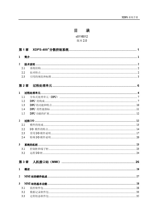
1 过程处理单元 ................................................................................................................................................ 6 1.1 分布式处理单元(DPU) .................................................................................................................... 7 1.2 DPU 的构成.......................................................................................................................................... 7 1.3 DPU 的功能和特点 ............................................................................................................................. 10 1.4 DPU 的性能指标 .................................................................................................................................11 1.5 DPU 功能的扩展 ................................................................................................................................. 12
Recom Power RMOD500-W DC-DC 转换器说明书

DC/DC Converter2BASIC CHARACTERISTICSParameterConditionMin.Typ.Max.Input Voltage Rangenom. V IN = 48VDC 32VDC 48VDC 96VDC Under Voltage Lockout (UVLO)DC-DC ON 29VDC 30VDC 31VDC DC-DC OFF 27VDC 28VDC 29VDC hysteresis 1VDC2VDC 3VDC Input Current V IN = 32VDC 18A 19A Inrush Current 10AQuiescent Current V IN = 48VDC80mA V IN = 72, 80VDC V OUT = 12.4/13.7VDC 40mA V OUT = 24VDC 50mA Standby Current V IN = 48VDC V OUT = 12.4/13.7VDC 6mA V OUT = 24VDC20mA Start-up TimeV IN = 48VDCfrom V IN = Turn-on, threshold to10% V OUT650ms 800ms from CTRL = on to 10% V OUT 250ms400msThe RMOD500-W DC-DC converter is ideally for the use in all off-highway electric vehicles. This family is an extremely robust plug & play module with 500 Watts, which generates the isolated Vout = 12,4 / 13,7 / 24,5VDC low voltage network from the traction battery level. The wide input voltage range 32-96V covers the common 48V and 80V battery voltages in this off-highway segment. Thanks to the waterproof and dust proof housing construction, the devices can directly be connected mechanically and thermally to the chassis (i.e. at any point on the vehicle) and operate reliably even under the most adverse conditions.E224736RoHS 2+compliant 10 from 10REACHcompliantNotes:Note1: Efficiency is tested at nominal input and 100% +25°C ambientmax. Output Power nom. Input VoltageRMOD500-60- SW/Part NumberInput Voltage Range[VDC]nom. Output Voltage[VDC]max. Output Current [A]Efficiency min.(1)[%]RMOD500-60-13.7SW 32-9613.736.589.5 RMOD500-60-13SW/OR 32-961338.589.5RMOD500-60-12.4SW 32-9612.44088.2RMOD500-60-11.7SW/OR 32-9611.742.588.2RMOD500-60-24.5SW 32-9624.52191.5RMOD500-60-23.5SW/OR32-9623.52191.5500 Watt4.53” x 8.0”Single OutputOR (ORing Diode)S inglenom. Output VoltageUL62368-1 certifiedCAN/CSA-C22.2 No. 62368-1 certified EN62368-1 certifiedp re li mi n a ryPROTECTIONSParameterTypeValueInternal Input Fuse 500V/30A Fast-acting fuse Short Circuit Protection (SCP)hiccup mode, automatic recoveryInput Reverse Polarity Protection-96VDCOver Voltage Protection (OVP)RMOD500-60-12.4SW and RMOD500-60-11.7SW/OR17VDC typ., hiccup mode, auto recovery RMOD500-60-13.7SW and RMOD500-60-13SW/OR 17-19VDC, hiccup mode, auto recoveryRMOD500-60-24.5SW and RMOD500-60-23.5SW/OR28-30VDC, hiccup mode, auto recoveryOver Current Protection (OCP)RMOD500-60-12.4SW and RMOD500-60-11.7SW/OR50A, hiccup modeRMOD500-60-13.7SW and RMOD500-60-13SW/OR 39-51A, hiccup mode RMOD500-60-24.5SW and RMOD500-60-23.5SW/OR23-27A, hiccup modeOver Voltage Categoryaccording to UL62368-1OVCIOver Temperature Protection (OTP) (3)measured on NTC 118°C typ., automatic restartIsolation Voltage (4)I/P to O/P; I/P to case2250VDC O/P to case 550VDCIsolation Resistance I/P to O/P 10M Ω min.Isolation CapacitanceI/P to O/P 5000pF typ.Notes:Note3: If the temperature exceeds the preset temperature threshold the module will shut down Note4: For repeat Hi-Pot testing, reduce the time and/or the test voltagen a ry-40-30-20020401006070-101030508090809010060705040302010O u t p u t C u r r e n t [%]Ambient Temperature [°C]SAFETY AND CERTIFICATIONSAudio/Video, information and communication technology equipment - Part1: Safety requirements E224736-A6023-ULUL62368-1:2014CAN/CSA-C22.2 NO. 62368-1:2014EN62368-1:2014 + A11:2017RoHS2ROHS-2011/65/EU + AM-2015/863ENVIRONMENTAL (RAILWAY STANDARDS)ParameterConditionValueTemperature ShockTemperature range:-40~125°C Thermal rate: 20°C/min Dwell time : 60mins Total cycle: 300cyclesISO 16750-4VibrationSine wave1.Frequency ( Hz ) amplitude acceleration 5 – 9 HZ ±15 mm 15-200 HZ 10G2. Sweep rate 1 Oct / min.3. Duration 50 Cycles.IEC 60068-2-6:Sine-wave vibration, test FcSubmersion testTotal cycles : 10Dwell time at Tmax : 1h Transition duration : <20s Test-fluid: De-ionized water,5% NaClWater Temperature:<4°C Immersion Time : 5 mins ISO 16750-4Mechanical Shock 50G/11ms 3Shocks for each direction IEC 60068-2-27: Shock, half sine, test EaSalt SprayOperating /no load1. Salt Spray Concentration:5%;2. Test Temperature:35°C;3. Volume of spray:1~2ml/hour/80cm2;4. PH:6.5~7.2;5. Test Time:96hours6. Tolerance: Salt Spray Concentration (±1%); Test Temperature: ± 2°C;IEC 60068-2-11:Test KaDerating Graph (5)(@ Chamber and natural convection 0.1m/s)Notes:Note5: Mount the device on a sufficient heatsink, the baseplate temperature should never exceed 90°C.p re li mi n a ryParameterConditionValueBump 40G/6ms 1000 Shocks for each directionIEC 60068-2-29: Bump, test EbEmission 30-1000MHz 34-45dBuV/m EN12895-2015Immunity 20V/m /27-1000MHz AM; 3V/m /1-2GHz AM; 1V/m /2-2.7GHz AM EN12895-2015,EN61000-4-3ESDDirect: ±8KV; Air: ±15KV EN12895-2015,EN61000-4-2PACKAGING INFORMATIONParameterType ValuePackaging Dimension (LxWxH)cardboard box 500.0 x 300.0 x 200.0mmPackaging Quantity 6pcsStorage Temperature Range-40°C to +105°CThe product information and specifications may be subject to changes even without prior written notice.The product has been designed for various applications; its suitability lies in the responsibility of each customer. The products are not authorized for use in safety-critical applications without RECOM’s explicit written consent. A safety-critical application is an application where a failure may reasonably be expected to endanger or cause p re li mi n。
施耐德电气 Symmetra

技术数据 .......................................................................................................8
设备规划 .....................................................................................................22
输入规格 ..................................................................................................22 旁路规格 ..................................................................................................22 输出规格 ..................................................................................................22 电池规格 ..................................................................................................23 带维修旁路的系统概述 ..............................................................................23
北京动力源DUM-48-50B开关电源系统使用说明
第一章目录第一章:概述第二章:安装1.安装环境检查及通风和防尘要求2.交流容量及连线要求3.直流容量及连线要求4.电池连线要求5.接地6.其它电缆连线7.调试第三章:电源系统第四章:控制系统第五章:交直流配电第六章:操作第七章:机械性能第二章概述一.简介随着通讯技术的发展,新型通讯设备的迭出,对通讯电源提出了更高的要求。
DUM-48/50B智能开关通信电源是采用新型元器件设计、生产的新一代高频开关电源。
具有容量大、可靠性高、智能化程度高、电网适应范围宽、维护方便等特点。
适用于邮电通信、移动通信基站、水利电力、公安、铁路、计算中心等需要大功率直流电源的场所。
二.系统特点1.DUM-48/50B智能开关通信电源交流输入电压适应范围宽:三相供电266V~494V2.DUM-48/50B智能开关电源整流器交流输入为三相无零线供电方式,彻底解决零线电流问题。
3.整流器具有缺相检测、保护电路。
可以保证在有一相相电压失效的情况下(例如:一相断路),整流器仍能在一定范围内正常工作。
整流器的输出电流不超过25A,整流器不受输入端缺相的影响,继续工作。
倘若,因为整流器输出端负载的变化,一旦输出电流超过了25A,此时整流器输出电流会自动限流于25A处。
4.DUM-48/50B智能开关通信电源整流器采用无源功率因数校正技术,功率因数≥0.92。
5.整流器逆变整流部分采用先进可靠的全桥PWM相移谐振ZVZCS拓扑结构, 与其他拓扑结构相比,它有效地提高了整流器的效率(达到91%以上)。
6.DUM-48/50B智能开关通信电源采用民主均流技术,提高了系统可靠性,减少了设备日常维护工作。
7.DUM-48/50B智能开关通信电源采用微机控制、汉字显示、键盘操作,极大地方便了用户掌握使用。
实现了系统的自动测试、自动诊断、自动控制,又可实现系统的遥信、遥测和遥控。
8.系统控制器对设置的参数具有掉电保护功能。
9.整流器采用智能风冷技术,当整流器温升到启动值时,风扇自动开启,大大提高了风扇使用寿命。
DM500产品说明书
DM-500全数字式交流伺服系统安装操作手册南京华兴数控技术有限公司目录第一章安全警告 (1)1.1与安全有关的符号说明 (1)1.2产品的警告标识 (1)1.3警告标志的内容 (1)1.4安全注意事项 (2)第二章概述 (5)2.1产品简介 (5)2.2运行模式简介 (5)第三章订货信息 (6)3.1驱动器规格 (6)3.2隔离变压器规格 (9)第四章安装 (10)4.1货到检查 (10)4.2安装环境 (10)4.2.1 防护要求 (10)4.2.2 温度要求 (10)4.2.3 振动和冲击 (10)4.3伺服驱动器安装 (11)4.4伺服电机安装 (13)第五章接线 (14)5.1标准接线 (14)5.2信号与功能 (23)5.2.1 端子配置 (23)5.2.2 电源端子TB (23)5.2.3 控制信号输入/输出端子CN2 (24)5.2.4 反馈信号端子CN1 (26)5.3接口电路 (27)5.3.1 开关量输入接口 (27)5.3.2 开关量输出接口 (27)5.3.3 脉冲量输入接口 (27)5.3.4 伺服电机光电编码器输入接口 (28)第六章操作与显示 (29)6.1键盘操作 (29)6.2参数设置(PA-) (29)6.3参数监视(DP-) (30)6.4参数管理(EE-) (31)6.5速度试运行(SR-) (32)6.6点动运行(JR-) (32)第七章参数 (33)7.1参数简介 (33)7.2参数功能 (34)7.3驱动器更换配套伺服电机 (38)7.4伺服驱动器参数调试 (39)7.5驱动器故障解决 (42)第八章运行调整 (45)8.1电源接线 (45)8.2通电测试 (46)8.3调整 (47)8.3.1 基本增益 (47)8.3.2 电子齿轮的设置 (48)8.3.4 启停特性调整 (48)第九章故障诊断 (50)9.1保护诊断功能 (50)9.2故障分析 (51)第十章保养与维护 (54)10.1日常检查 (54)10.2定期检查 (54)10.3部件替换指南 (54)第一章安全警告感谢您选用DM-500交流伺服系统。
动力源DUK-4850B监控模块关键参数设置

是否保存全部设置 保存 放弃
设置电源参数 浮充电压 52.0V 交流上限 280V 均充电压 56.0V 交流下限 180V 直流上限 59.0V 频率上限 55.0Hz 直流下限 43.0V 频率下限 45.0Hz 一次下电 45.0V 交流过流 100A 二次下电 43.0V 温度上限 50.0℃
动力源DUM-48/50D2 电源系统关键工作参数设置指南
C
参数显示屏
返回键
确认键
DUK-48/50B
动力源DUM-48/50D2 电源系统 DUK-48/50B监控模块操作面板图
1
点击此处添加标题
点击此处添加正文
2
点击此处添加标题
点击此处添加正文
系统名称
监控模块型号
参数名称
参数作用
设置方法
DUM-48/50D(30C) DUM-48/50B
设置电源参数 浮充电压 52.0V 交流上限 280V 均充电压 56.0V 交流下限 180V 直流上限 59.0V 频率上限 55.0Hz 直流下限 43.0V 频率下限 45.0Hz 一次下电 45.0V 交流过流 100A 二次下电 43.0V 温度上限 50.0℃
设置电池参数 电池组数 01组 充电限流 39A 每组标称 700AH 转换电流 8.7A 每组实际 700AH 充电保持 8M 温补系数 5mV 试验电压48.0V 充电系数 1.00 电保电压42.9V 均充周期 12天
Step3:在设置电池参数界面配置正确的均充周期及转换电流参数: 1、在监控模块上按↑↓键将光标移至均充 周期菜单栏; 2、按→←键将均充周期设置为与电池厂商 沟通确认好后的均充周期值,按确认键 确认;康普电池可设置为90天; 3、在监控模块上按↑↓键将光标移至转换 电流菜单栏; 4、按→←键将转换电流设置为0.01C10,按 确认键确认;
NSD500技术说明书
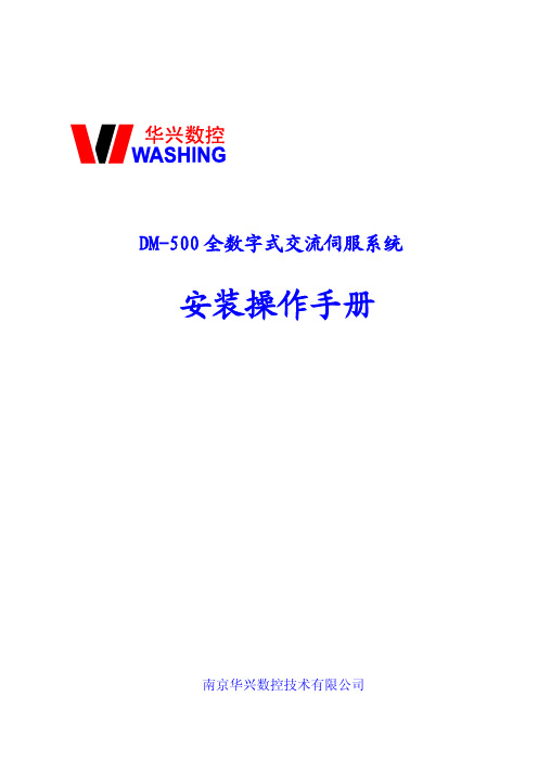
1.概述NSD500系列高压变电站单元测控装置是以变电站内一条线路或一台主变为监控对象的智能监控设备。
它一方面采集本间隔内的实时信号,另一方面可通过智能通讯模件与本间隔内的其他智能设备(例如保护装置)通讯,同时通过双以太网接口直接上网与站级计算机系统相连,构成面向对象的分布式变电站计算机监控系统。
NSD500装置由一个标准4U主机箱和多个扩展I/O模件组成,也可根据需要扩展一个辅助机箱用以扩展I/O。
主机箱内包括了电源、智能人机接口、以太网通讯模件、CPU模件和智能通讯模件。
扩展的I/O模件均为智能模件。
NSD500单元测控装置各部分功能框图见下图。
NSD500模件功能如下表:表:NSD500系列单元测控装置模件功能一览表序号型号名称主要功能1NSD500-NET双以太网接口模件提供双路以太网接口2NSD500-CPU CPU模件数据集成,控制闭锁3NSD500-IED智能通讯模件与智能设备通讯4NSD500-MMI智能人机接口模件提供当地显示及操作界面5NSD500-DIM智能开入采集模件24点开入信号采集6NSD500-DOM智能控制模件6个对象控制7NSD500-AIM智能直流采集模件8路直流模拟量信号采集8NSD500-ACM智能交流采集模件3CT+3PT交流输入,一条线路的交流量采集计算9NSD500-DLM智能断路器控制模件需同期的断路器控制10NSD500-PTM智能交流电压采集模件6PT交流输入11NSD500-PWR电源模块提供装置电源12NSD500-BB背板电源、信号线连接13NSD500-RLY扩展继电器插箱与DOM配套,扩展控制输出接点和容量LED LCD控制操作键盘远方/当地切换开菜单操作键盘调试口联锁/解锁切换开图 NSD500 装置正视图NSD500测控装置的实时数据有两类,一类为本装置采集的实时数据,如接入本装置的开关量输入信号、交流信号、直流信号等;另一类为通过以太网接收到的其他装置的开关量信号,我们将这种数据称为虚拟开入。
电源说明书
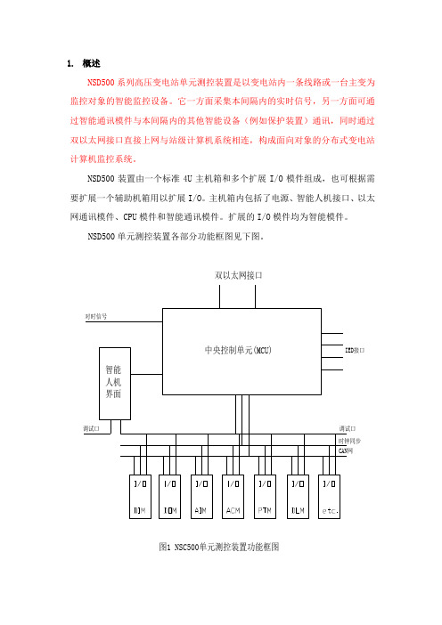
电源说明书1、性能特点及适用范围KBA500CB220D24/48I是我司设计生产的充电式模块电源,输入、输出端为接线端子形式便于连接;本产品具有智能充电功能,可对外接的48V电池充电,在交流断电时电池可不间断的对负载供电,具有防止电池过放电的保护功能;具有电源的状态显示;具有电池活化功能,手动或通过外部信号自动对电池进行活化维护。
本电源适用于电力配网自动化系统,电力智能箱变,环网柜以及其他行业需要不间断直流供电,要求较高的场合。
2、技术参数平均无故障时间(h)室温条件下80000----3.电源内部电路原理图1 电源内部原理图4、电源接线说明图2 接线示意图接线说明:K1 K2 K3 K4为用户CPU等控制的继电器触点(触点容量无要求,但不可用光耦代替), R1,R2,R3,R4为告警信号串联负载,告警结点带负载能力1~5mA。
电池为48V电池组。
接线端子容量300V/15A。
具体使用见下面使用说明。
4.1端子定义5、使用说明5.1 电源状态指示24V电源指示灯:V o2+ V o2-有输出时亮,无输出时灭;48V电源指示灯:V o1+ V o1-有输出时亮,无输出时灭;电池欠压指示灯:电池欠压时亮,否则熄灭;电池活化指示灯:电池活化时亮,否则熄灭;电池充电指示灯:电池充电时亮,电池放电或电池活化时熄灭;电池放电指示灯:电池放电时亮,电池充电及电池放电结束时熄灭;A相电源指示灯:A相电源有电时亮,失电时灭;B相电源指示灯:B相电源有电时亮,失电时灭;5.2按键功能及使用活化ON,轻触式按键,电池活化手动启动;活化按键,按一下活化ON键则电源进入电池活化状态,此时放电指示灯亮,活化指示灯亮,电池对负载放电。
5.3电源的使用5.3.1 本电源在输入交流电后即可工作,电源本身对负载输出电流,同时为电池进行恒流恒压充电,当电池充电完成后,电源自动转为浮充电状态,此时电源提供浮充电压及电流补充电池的正常自放电;5.3.2 A,B相交流断电时,电池不间断为负载供电,0切换时间,当电池放电至欠压告警点时,输出电池欠压告警信号,当电池放电低于欠压保护点时,电源自动关闭负载输出;如果需要提前关断电池输出,可由遥控由CPU控制的继电器把电源的电池遥控退出端子B G与V G短接一次(不小于5秒)则电池提前关断。
- 1、下载文档前请自行甄别文档内容的完整性,平台不提供额外的编辑、内容补充、找答案等附加服务。
- 2、"仅部分预览"的文档,不可在线预览部分如存在完整性等问题,可反馈申请退款(可完整预览的文档不适用该条件!)。
- 3、如文档侵犯您的权益,请联系客服反馈,我们会尽快为您处理(人工客服工作时间:9:00-18:30)。
外形尺寸 工作环境温度(℃) 工作壳温(℃) 存储温度(℃) 重量(Kg) 平均无故障时间(h)
168mm * 110mm * 45mm 室温条件下
-ห้องสมุดไป่ตู้0
--
-40
--
-40
--
--
1.2
80000
--
+70 +85 +105 ---
2
三、EMC(电磁兼容)
DMN500-48 充电电源技术规格书
0.65
0.7
充电电流精度(%)
Vi=165~265Vac,典型负载
--
3
5
电池放电关断点(V) 典型负载
41
42
43
电池活化完成点(V) 典型负载
44
45
46
电池欠压告警点(V) 典型负载
43
44
45
电池放电关断延时(S) 典型负载
30
45
60
电池放电回路内阻(Ω) 放电电流 25A
--
0.05
--
全范围输入,不含充电电流(环境温度为 25)
全范围输入,不含充电电流(环境温度为 55)
输出电流(A)
全范围输入,冲击电流≥5A,≤12.5A(60S 关闭 AC/DC,20 分钟重启)
全范围输入,冲击电流≥12.5A,≤18A(20S
关闭 AC/DC,20 分钟重启)
现改为:
输出电流(A) 冲击负载限时(S)
如果冲击负荷在 5A~12.5A ±5% 范围时,计时 60 秒后进入保护状态;如果冲击负荷在 12.5A~18A ±5% 范围,计时 20 秒后进入保护状态。20 分钟后自动重启 现改为: 模块具有带 500W 负载、耐受时长≥20S 冲击的能力 2、参数部分 V2.01 版,输出特性输出电流部分如下
有防止电池过放电的保护功能; 具有电源的LED状态显示; 具有电池活化功能,手动或通过外部信号自动对电池进行活化维护; 模块具有带500W负载、耐受时长≥20S冲击的能力。
二、技术参数
DMN500-48 技术参数表
输入特性
项目
测试条件
最小
输入电压范围(Vac) 输出满载
165
输入电压范围(Vdc) 输出满载
漏电流 5mA, 隔 离 电 工频 50Hz, 压(Vac) 1min 无击穿
或散络
测试条件
输入对输出 输入对机壳 输出对机壳 40±2℃ AC 典型输入、典型负载、电池充满 输入对输出 输入对机壳 输出对机壳
最小 -50 50 50 0 --
典型 -----88 2500
2500
2500
最大 ±0.05
2
一、产品简介
DMN500-48 充电电源技术规格书
产品适用于电力配网自动化系统,电力智能箱变,环网柜以及其他行业需要不间断直流 供电,要求较高的场合。 1、 产品命名
根据我司推出的一系列电源装置的命名规则,本电源模块命名为DMN500-48,中文名称为 充电电源。 2、 产品的功能 体积小,转换效率高,性能稳定,原副边隔离,隔离强度高; 金属外壳模块化灌封封装,防尘防潮、抗干扰能力强; 输入、输出端为带法兰接线端子,连接方便、可靠; 电网适应能力强,可在较宽输入电压范围内工作; 具备电池欠压保护、输出过载/短路保护、电池反接保护、过压等保护功能; 智能充电功能,可对外接的48V电池充电,在交流断电时电池可不间断的对负载供电,具
雷击(浪涌)干扰
测试方法及要求:
1、 模块输入电源 AC220V,输出负载 0.3A;电池口 0.3A
2、模块的输入(AC220V),输出负载口、电池口接入差模±2KV、共模±4KV 冲击浪涌;测试浪涌间隔 60S,
被测回路(交流输入、负载输出端、电池输出端)各电压、极性测试 3 次。
3、 受测试的模块在试验期间应能正常工作,无误报警、无损坏现象。
200
频率(Hz)
交流输入
40
输出特性 项目
输出电压(V)
输出电流(A)
测试条件 AC 全范围输入(均充) AC 全范围输入(浮充) AC 失电,电池供电 全范围输入,不含充电电流(环境温度为 25) 全范围输入,不含充电电流(环境温度为 55) 全范围输入,冲击电流≥5A,≤12.5A(60S 关闭 AC/DC,20 分钟重启)
1
最小 55.4 53.4 42
0
0
典型 220 300 50
最大 265 375 60
典型 56 54 -3.8 1
--
最大 56.6 54.6 57 4.3 1.1
12.5
DMN500-48 充电电源技术规格书
全范围输入,冲击电流≥12.5A,≤18A(20S
关闭 AC/DC,20 分钟重启)
18
冲击负载限时(S)
全范围输入,功率 500W
20
--
--
纹波噪声(mVp-p)
全范围输入,典型负载
--
--
500
源效应(%)
AC 全范围输入,典型满载
--
--
±0.5
负载效应(%)
AC 典型输入,负载在 10%~100%之间变化
--
--
±1.0
电池恒流充电电流(A) AC 全范围输入,典型负载
0.6
测试对象
测试模式
测试电压
测试次数
全范围输入,不含充电电流(环境温度为 25) 全范围输入,不含充电电流(环境温度为 55) 全范围输入,功率 500W
-0 0
--
最小
0 20
3.8
4.3
1
1.1
--
12.5
--
18
典型 3.8 1 --
最大 4.3 1.1 --
V2.03 版更改如下: 1、原第六部分面板说明,描述如下 故障:红色,电源输出过压,模块过温,过冲保护,或电池反接时(有交流电时)亮;冲击负载时, 闪烁;否则熄灭。 现改为: 故障:红色,电源输出过压,模块过温,过冲保护,或电池反接时(有交流电时)亮;冲击负载时, 无点亮,无闪烁,达到 60S 限时后自动关闭 AC/DC。
DMN500-48 充电电源技术规格书 文件编号
DMN500-48 电源技术规格书
版本号 V2.03
编写 日期 审核 日期 批准 日期
珠海赛迪生电气设备有限公司
二 0 一七 年 三 月 六 日
1
DMN500-48 充电电源技术规格书 V2.02 版更改如下: 1、原产品功能部分“冲击负载限时”描述如下:
电池最大放电电流(A) 放电时间≤60s
--
---
30
遥控活化启动、退出 活化触点接触时间(s)
遥控电池退出
--
0.5
1.0
0.5
1
1.5
输出过压保护(V)
关断输出
59
60
61
输出短路保护
AC 全范围输入
关断电源输出,撤销自动重启动
一般特性 项目 温度系数(%/℃)
绝缘电阻(MΩ)
相对湿度(%) 效率(%)